JP4236231B2 - Ozone exposure test method and ozone exposure test apparatus - Google Patents
Ozone exposure test method and ozone exposure test apparatus Download PDFInfo
- Publication number
- JP4236231B2 JP4236231B2 JP2000006942A JP2000006942A JP4236231B2 JP 4236231 B2 JP4236231 B2 JP 4236231B2 JP 2000006942 A JP2000006942 A JP 2000006942A JP 2000006942 A JP2000006942 A JP 2000006942A JP 4236231 B2 JP4236231 B2 JP 4236231B2
- Authority
- JP
- Japan
- Prior art keywords
- test
- ozone
- flow rate
- ozone exposure
- exposure test
- Prior art date
- Legal status (The legal status is an assumption and is not a legal conclusion. Google has not performed a legal analysis and makes no representation as to the accuracy of the status listed.)
- Expired - Fee Related
Links
Images
Description
【0001】
【発明の属する技術分野】
本発明は、オゾン暴露試験方法ならびにそれ用の装置に関し、より具体的には、インクジェットや印刷、昇華転写、熱転写、電子写真、銀塩写真、自己発色記録などに用いる紙やシートなどの媒体ならびに前記媒体上の画像を試験対象とするオゾン暴露試験方法とそれ用の装置に関する。
【0002】
【従来の技術】
近年、印刷やインクジェット、銀塩写真などの記録物の画像堅牢性が求められるようになってきている。特開昭63−252780号公報に記載されているように、オゾン暴露試験は、これらの記録物ならびにその記録媒体自体の室内褪色の発生を調べる方法として有効である。
【0003】
従来からオゾン暴露装置の提案はなされていたが、試験槽の温度や湿度を十分に制御する機構を具えていない装置もあった。日本ゴム協会誌第62巻第7号(1989)の423〜437頁には、オゾン試験およびオゾン試験機について記載がある。特に、その中でオゾン濃度の精密な測定方法は記載されている。また、スガテクニカルニュースNo.161(スガ試験機株式会社編集、平成10年12月25日発行)の8頁には、オゾン試験の場合、試験槽内容積の3/4(94L)を毎分置換することが決められていることが記載されている。しかしながら、オゾンの濃度が調整された気体の試験槽内の循環や試験槽内の循環流量については、前記両文献とも記載はなされていない。紙やシートなどの平面状の物質のオゾン暴露試験では、試験槽内のオゾン濃度だけでなく、試験槽内のオゾンを含む気体の循環流量によっても、オゾン暴露試験の結果が異なるという問題も指摘されている。
【0004】
【発明が解決しようとする課題】
上述するように印刷やインクジェット、銀塩写真などによる記録物の画像堅牢性を検証する上で、オゾン暴露試験は極めて有力な手段であるが、従来の方法は、試験結果の再現性ならびにその信頼性は十分なものではなかった。つまり、これら記録物ならびにその記録媒体自体の室内褪色の発生を高い精度で予測する目的に適する、再現性と信頼性の高いオゾン暴露試験方法を提案が望まれている。
【0005】
本発明は、前記の課題を解決するもので、本発明の目的は、高い再現性と信頼性を与える新たなオゾン暴露試験方法を提供することにある。より具体的には、紙やシートなどの平面状の物質のオゾン暴露試験に適用する際、その試験結果の再現性と信頼性が高い試験方法と、その方法に基づく試験に利用できる試験装置を提供することにある。
【0006】
【課題を解決するための手段】
本発明者は、上記の目的を達成するため、鋭意研究を進めた結果、インクジェットや印刷、昇華転写、熱転写、電子写真、銀塩写真、自己発色記録などに用いる紙やシートなどの媒体ならびに前記媒体上の画像は、その媒体自体吸水性または吸湿性の被試験材料であるが、これら吸水性または吸湿性の被試験材料のオゾン暴露試験において、被試験材料のオゾン暴露を行う試験槽内部の気体の循環流量とオゾン暴露による劣化に明確な相関があることを見出した。
【0007】
具体的には、従来のオゾン暴露試験機では、オゾン暴露試験を行う時にオゾン濃度が調整された気体を試験槽内部で循環させるが、試験槽内部の気体循環流量が少ない場合には、連続して暴露試験を行った際、1回目と2回目、更には3回目と回数を重ねると測定結果が一致しないことがしばしばある。一方、オゾン暴露試験中、試験槽内の気体循環流量を、毎分の流量を試験槽の容積の5倍以上とし、また、その際、気体循環流量の変動を設定値の±10%の以下に制御すると、オゾン暴露試験を連続で行っても、測定結果の再現性が良いことを見出した。かかる知見に基づき、本発明を完成するに至った。
【0008】
すなわち、本発明の提供する方法は、吸水性または吸湿性を有する平面状の被試験材料に対するオゾン暴露試験方法であって、試験槽から温度・湿度制御用の循環系を経由する気体循環によって、オゾン暴露試験中の試験槽内の温度、湿度を一定に保つ制御を行い、オゾン暴露試験中における試験槽内の気体循環流量を測定して、該試験槽内の気体循環流量を調節し、オゾン暴露試験中の試験槽内の毎分の気体循環流量が前記試験槽の内容積の5倍以上であり、かつオゾン暴露時の気体循環流量の変動が前記気体循環流量設定値の±5%以内であることを特徴とするオゾン暴露試験方法である。
【0009】
好ましくは、前記気体循環流量の変動を前記気体循環流量設定値の±5%の範囲内に制御する。このような気体循環流量の制御に加えて、前記オゾン暴露試験中、試験槽内のオゾン濃度をオゾン濃度設定値±3%以内に制御するとよい。また、試験槽内の気体循環とともに、前記オゾン暴露試験中、試験槽内に一定温度と一定湿度に調整された気体を導入して、試験槽内を一定温度、一定湿度に調整することが好ましい。
【0010】
さらに、本発明にかかるオゾン暴露試験方法は、吸水性または吸湿性を有する平面状の被試験材料に対するオゾン暴露試験に使用されるオゾン暴露試験装置であって、該オゾン暴露試験装置は、試験槽から温度・湿度制御用の循環系を経由する気体循環によって、オゾン暴露試験中の試験槽内の温度、湿度を一定に保つ制御機構と、オゾン暴露試験中における試験槽内の気体循環流量を測定して、流量を調節する機構を具え、オゾン暴露試験中の試験槽内の毎分の気体循環流量が前記試験槽の内容積の5倍以上であり、かつオゾン暴露時の気体循環流量の変動が前記気体循環流量設定値の±5%以内であることを特徴とするオゾン暴露試験装置を利用することによって、確実に実施することができる。
【0011】
【発明の実施の形態】
本発明のオゾン暴露試験方法は、上記のように気体循環を行って、オゾン暴露試験中試験槽のいずれの場所でもオゾンを所定濃度に維持しすることで、繰り返し測定を行った際、各試験毎の再現性を高いものとする。特に、被試験試料の表面積が広くなる紙やシートなどの媒体ならびに前記媒体上の画像を試験対象とする際、これら吸水性または吸湿性に富む媒体において、その表面面上に含まれる水分量を均一にするので、試料面内の分布を無くし、試験結果の再現性を高めるのみでなく、試験自体の信頼性も高くできる。
【0012】
以下、本発明のオゾン暴露試験方法、それに用いる装置について、図を参照しつつ、より具体的に説明する。
【0013】
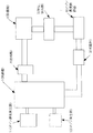
図1は、本発明のオゾン暴露試験方法に好適な試験装置構成の一例を示す概略図である。オゾン暴露試験の際、被試験試料は試験槽1の内部に、所定の試験時間放置し、オゾン暴露が行われる。その間、試験槽1内を所定のオゾン濃度に維持するため、オゾン濃度測定器11により、オゾン濃度を逐次モニターする。自然失活や、暴露される被試験試料による消費により、減少するオゾンを補うため、オゾン発生器12からオゾンが供給される。
【0014】
図1に示す装置構成では、試験槽1に対して、槽の上端付近にオゾン濃度測定器11を、槽の下端付近にオゾン発生器12をそれぞれ配置している。また、槽の上端付近には、試験槽1から温度・湿度制御用の循環系への排出口、一方、槽の下端には、前記温度・湿度制御用の循環系から試験槽1への注入口が設けられている。この注入口から排出口への気体の流れに伴い、オゾン発生器12から連続的に供給されるオゾンは槽中央部に運ばれ、試験において消費される。温度・湿度制御用の循環系は、試験槽1の排出口より気体を取り込む送風機3、その下流に、除湿機4、加温・加湿器5、オゾン濃度調節器6が順に配置されている。また、前記循環系から試験槽1への注入口へ戻される気体流量を測定する流量計2が、循環系路の最下流部に設置されている。
【0015】
試験槽1からオゾンを含む気体が送風機3により取り込まれるが、この気体中には、オゾン暴露試験に伴い発生したガス類、あるいは浮遊微粒子なども混入することも多い。必要に応じて、前記微粒子などを取り除くフィルターやガス類を取り除くフィルターなどを循環系に付設することができ、例えば、送風機3の取り込み口には取り付けると好ましい。送風機3により取り込まれた気体は除湿機4にて、気体を冷却して温度を下げ、含まれる水分を除去する。次いで、冷却・除湿された気体は、加温、加湿器5に通され、ヒーターなどで気体を加熱して所定の温度まで加温する。同時に、水蒸気などを添加して、所定の湿度まで加湿を行う。以上の冷却・除湿過程と加温・加湿過程の間に、一般に気体中に含まれるオゾン濃度は次第に低下する。気体は、オゾン濃度調節器6に通され、残存するオゾン濃度の測定を行う。その際、残存するオゾン濃度が所定の濃度を下回る場合、オゾン濃度調節器6において、所定の濃度になるまでオゾンが添加される。
【0016】
この温度・湿度制御用の循環系を経てきた循環気体は、最後に設けた流量計2において、その流量が測定される。例えば、流量計2として、風量計を用いて、風量を測定して、循環流量に換算することができる。この流量計2(風量計)で測定された循環流量(風量)は図示しない制御系により送風機3にフィードバックされて、循環流量と循環流量の変動を所定の範囲内に制御される。
【0017】
本発明の方法においては、オゾン暴露試験中の試験槽内の気体循環流量は、毎分の流量を試験槽の内容積の5倍以上に設定し、かつ気体循環流量の変動を前記設定値の±10%の範囲内に制御する。好ましくは、変動幅を、設定値の±5%の範囲内に制御する。上記の図1に示す構成の装置においては、試験槽内の気体の循環は、主に試験槽から取り出す循環により行われている。なお、本発明の方法では、上述する試験槽から取り出す循環以外に、試験槽の内部循環を主とする形態も含まれる。さらに、一部の気体を循環系から外部に排出して、排出した量を補うべく、新たな気体を外部から供給する循環系をも含む。加えて、本発明においては、オゾン濃度測定器11とオゾン発生器12は、循環系統とは別に設ける構成をとることもできる。
【0018】
さらに、試験槽内の気体循環流量の変動幅を設定値の5%の範囲内で制御すると、被試験試料の色材などの拡散を防止することができる。例えば、流量を高くするに従い、大きな流量変動(脈動)に因る被試験試料の振動誘起も相対的に強くなり、それに伴い、粉末化した色材などの微粒子の飛散・拡散も拡大するが、流量の変動幅を設定値の5%の範囲内で制御すると前記の脈動現象などは生じず、被試験試料の色材などの拡散も有効に防止される。従って、紙やシートなどの媒体上の画像を試験対象とする際、拡散する色材などに起因する系統誤差の抑制が可能となり、より信頼性の高い試験方法となる。
【0019】
本発明のオゾン暴露試験方法においても、試験槽内は一定温度、一定湿度に制御されることが好ましい。すなわち、試験槽内の温度、湿度を一定に保つことによって、被試験試料が吸水性または吸湿性の材料であっても、試験毎に、各試料中に含まれる水分量の変動を起こすことなく、再現性の良い測定を行うことができる。加えて、本発明の方法においては、オゾン濃度の変動幅は設定値の±3%以内が好ましい。この変動幅の範囲内であれば、暴露時間に依存せず、オゾン濃度による測定値の変化を抑えて正確な試験を行うことができる。なお、本発明の方法では、試験槽内の気体循環流量は、毎分の流量を試験槽の内容積の5倍以上とするので、オゾン濃度の変動幅を実質的に抑えることができる。従って、例え、瞬時的にオゾン濃度の急激な変化(減少)が生じたとしても、僅かの間に、前記の変化(減少)を均一化・回復させて、オゾン濃度の変動幅を設定値の±3%以内に均衡する作用をも有する。
【0020】
本発明のオゾン暴露試験装置は、試験槽内の気体循環流量を測定し、流量を調節する機構を具える装置であるが、例えば、上で説明した図1に示す装置構成はその好ましい形態の一例である。即ち、図1に示す装置構成では、試験槽内の気体循環流量の測定と、その流量を調節する機構は、試験槽とは分離して循環系内に配置されており、加えて、循環する気体自体の温度・湿度、さらには、オゾン濃度をも所定値に制御できる構成であり、一層好ましい装置である。
【0021】
【実施例】
以下に具体例を挙げて、本発明のオゾン暴露試験方法ならびに、この方法において結果の高い再現性と信頼性が達成されることを示す。なお、以下の具体例は、本発明の最良の実施形態の一例ではあるが、本発明は、かかる具体的な形態に限定されるものではない。
【0022】
実施例1〜3
オゾン試験装置(製品名:オゾンウェザオメーター、スガ試験機社製)の試験槽と温度・湿度制御の循環系に風量計を入れて、図1に示す装置構成と同等の構成とした。また、風量計により測定される循環流量測定値に基づき、送風機の送風量(循環流量)を制御する機構を取り付けた。このオゾン試験装置に被試験試料を入れて、以下の条件でオゾン暴露試験を行った。表1に、各実施例において、前記オゾン試験装置の試験槽内に循環させる気体循環流量の設定値、その流量制御における変動幅を示す。なお、試験槽内の温度・湿度は、温度・湿度制御の循環系により一定化を行った。
【0023】
【表1】

試験槽の温度 :45℃
試験槽の湿度 :55%RH
オゾン濃度 :3ppm
暴露試験時間 :120分間
被試験試料は以下のようにして得た。印字媒体の紙は、乾燥固形分換算で3:1の比率でシリカ(サイリシア450、富士シリシア化学社製)とポリビニルアルコール(NH−18、日本合成化学社製)を混合した混合物を、乾燥固形分量20g/m2の厚みで市販の電子写真用紙(EN−500、キヤノン社製)表面に塗工した紙を用いた。この紙上に、インクジェットプリンター(BJC430、キヤノン社製)でデューティ100%の黒べたパターンを20×20mmの大きさで印字したものを被試験試料とした。オゾン暴露試験では、前記印字パターンの褪色を評価した。
【0025】
褪色は、オゾン暴露前後に、印字パターンの光学濃度を濃度計(310TR、X−1ite社製)で測定して、その残存率を下記の式で計算した。
残存率(%)=オゾン暴露後の光学濃度/オゾン暴露前の光学濃度*100
各実施例とも、再現性を検証する目的で、同じ操作でオゾン暴露試験を連続して5回行った。また、各実施例間において、結果を比較することにより、試験結果の信頼性、バラツキを検証した。
【0026】
表2に、各実施例の試験結果を併せて示す。表2に示す結果から、試験槽内の気体循環流量を、毎分の流量を試験槽の内容積の5倍以上に設定し、また、流量の変動幅を設定流量の10%以内に制御した結果、各条件(実施例内)において、再現性は良好であることが判る。また、各実施例相互を比較しても、結果のバラツキはなく、オゾン暴露試験自体信頼性の高いものであることが判る。特に、流量の変動幅を設定流量の5%以内に制御する実施例3においては、より再現性が高いものとなっている。
【0027】
【表2】
【発明の効果】
本発明のオゾン暴露試験方法によれば、オゾン暴露試験中、試験槽内の気体循環流量を、毎分の流量を試験槽の内容積の5倍以上に維持し、また、その変動を設定流量の10%以内に制御した結果、以下の効果が生じた。すなわち、被試験試料の水分量を制御してオゾン暴露を行うことができ、連続して多数回のオゾン暴露試験を行った際、試験結果の再現性が良くなる。加えて、温度と湿度を調整し、オゾン濃度を調整した空気を前記の循環流量にて試験槽に送ることにより、試験槽内のオゾン濃度の安定性が一層良くなる。これらの効果により、再現性が高くなるのみでなく、試験自体の信頼性も高くなる利点を有する。
【図面の簡単な説明】
【図1】本発明の方法に基づくオゾン暴露試験に用いられる試験装置構成の一例を示す模式図である。
【符号の説明】
1 試験槽
2 流量計(風量計)
3 送風機
4 除湿機
5 加温、加湿器
6 オゾン濃度調節器
11 オゾン濃度測定器
12 オゾン発生器[0001]
BACKGROUND OF THE INVENTION
The present invention relates to an ozone exposure test method and an apparatus therefor, and more specifically, a medium such as paper or sheet used for inkjet, printing, sublimation transfer, thermal transfer, electrophotography, silver salt photography, self-coloring recording, etc. The present invention relates to an ozone exposure test method for testing an image on the medium and an apparatus therefor.
[0002]
[Prior art]
In recent years, image fastness of recorded matter such as printing, ink jet, and silver salt photography has been demanded. As described in Japanese Patent Laid-Open No. 63-252780, the ozone exposure test is effective as a method for examining the occurrence of indoor fading in these recorded materials and the recording medium itself.
[0003]
Conventionally, ozone exposure devices have been proposed, but there are also devices that do not have a mechanism for sufficiently controlling the temperature and humidity of the test tank. On pages 423 to 437 of Journal of Japan Rubber Association Vol. 62, No. 7 (1989), there is a description of an ozone test and an ozone tester. In particular, a precise measurement method of ozone concentration is described therein. Also, Suga Technical News No. 161 (edited by Suga Test Instruments Co., Ltd., issued on December 25, 1998), in the case of the ozone test, 3/4 (94L) of the test tank volume is decided to be replaced every minute. It is described that. However, neither of the above-mentioned documents describes the circulation of the gas in which the ozone concentration is adjusted and the circulation flow rate in the test tank. In the ozone exposure test of flat materials such as paper and sheets, it was pointed out that the ozone exposure test results differ depending not only on the ozone concentration in the test chamber but also on the circulating flow rate of the gas containing ozone in the test chamber. Has been.
[0004]
[Problems to be solved by the invention]
As described above, the ozone exposure test is an extremely effective method for verifying the image fastness of printed matter by printing, ink-jet printing, silver salt photography, etc., but the conventional method uses the reproducibility of the test result and its reliability. Sex was not enough. That is, there is a demand for a highly reproducible and reliable ozone exposure test method suitable for the purpose of predicting the occurrence of indoor fading of these recorded materials and the recording medium itself with high accuracy.
[0005]
The present invention solves the above-described problems, and an object of the present invention is to provide a new ozone exposure test method that provides high reproducibility and reliability. More specifically, a test method with high reproducibility and reliability of the test results and a test device that can be used for tests based on that method when applied to an ozone exposure test of a planar substance such as paper or sheet. It is to provide.
[0006]
[Means for Solving the Problems]
As a result of earnest research to achieve the above object, the present inventor has developed a medium such as paper and sheet used for inkjet, printing, sublimation transfer, thermal transfer, electrophotography, silver salt photography, self-coloring recording, etc. The image on the medium is a material to be tested that absorbs or absorbs moisture, but in the ozone exposure test of these materials that absorb water or absorbs moisture, the inside of the test chamber that performs ozone exposure of the material to be tested is shown. It was found that there was a clear correlation between the gas circulation flow rate and the deterioration caused by ozone exposure.
[0007]
Specifically, conventional ozone exposure test machines circulate a gas whose ozone concentration has been adjusted when performing an ozone exposure test inside the test tank, but if the gas circulation flow rate inside the test tank is small, it will continue. When the exposure test is performed, the measurement results often do not match if the first and second times, and even the third time are repeated. On the other hand, during the ozone exposure test, the gas circulation flow rate in the test tank is set to 5 times or more the volume of the test tank, and the fluctuation of the gas circulation flow rate is less than ± 10% of the set value. It was found that the reproducibility of the measurement results was good even when the ozone exposure test was continuously performed. Based on this knowledge, the present invention has been completed.
[0008]
That is, the method provided by the present invention is an ozone exposure test method for a planar material under test having water absorption or hygroscopicity, and by gas circulation from a test tank via a circulation system for temperature / humidity control, Control to keep the temperature and humidity in the test chamber constant during the ozone exposure test, measure the gas circulation flow rate in the test chamber during the ozone exposure test, adjust the gas circulation flow rate in the test chamber, and The gas circulation flow rate per minute in the test chamber during the exposure test is more than 5 times the internal volume of the test chamber, and the fluctuation of the gas circulation flow rate during ozone exposure is within ± 5% of the gas circulation flow rate setting value. This is an ozone exposure test method characterized by
[0009]
Preferably, the fluctuation of the gas circulation flow rate is controlled within a range of ± 5% of the gas circulation flow rate set value. In addition to the control of the gas circulation flow rate, the ozone concentration in the test tank may be controlled within the ozone concentration set value ± 3% during the ozone exposure test. Further, it is preferable to adjust the inside of the test tank to a constant temperature and a constant humidity by introducing a gas adjusted to a constant temperature and a constant humidity into the test tank during the ozone exposure test together with the gas circulation in the test tank. .
[0010]
Furthermore, an ozone exposure test method according to the present invention is an ozone exposure test apparatus used for an ozone exposure test on a planar material under test having water absorption or hygroscopicity. Measures the control mechanism to keep the temperature and humidity in the test chamber constant during the ozone exposure test and the gas circulation flow rate in the test chamber during the ozone exposure test by gas circulation via the circulation system for temperature and humidity control And a mechanism for adjusting the flow rate, the gas circulation flow rate per minute in the test tank during the ozone exposure test is more than five times the internal volume of the test tank, and the fluctuation of the gas circulation flow rate during ozone exposure Can be reliably carried out by using an ozone exposure test apparatus characterized by being within ± 5% of the gas circulation flow rate set value.
[0011]
DETAILED DESCRIPTION OF THE INVENTION
The ozone exposure test method of the present invention performs the gas circulation as described above, and keeps ozone at a predetermined concentration at any place in the test tank during the ozone exposure test. The reproducibility of each is high. In particular, when the test object is a medium such as paper or sheet in which the surface area of the sample to be tested is widened and an image on the medium, the amount of water contained on the surface of the medium rich in water absorption or hygroscopicity is determined. Since it is uniform, not only the distribution in the sample surface is eliminated, the reproducibility of the test results is improved, but also the reliability of the test itself can be increased.
[0012]
Hereinafter, the ozone exposure test method of the present invention and the apparatus used therefor will be described more specifically with reference to the drawings.
[0013]
FIG. 1 is a schematic view showing an example of a test apparatus configuration suitable for the ozone exposure test method of the present invention. In the ozone exposure test, the sample to be tested is left in the test tank 1 for a predetermined test time to be exposed to ozone. Meanwhile, in order to maintain the inside of the test tank 1 at a predetermined ozone concentration, the ozone concentration is sequentially monitored by the ozone concentration measuring device 11. Ozone is supplied from the ozone generator 12 in order to compensate for the decrease in ozone due to natural deactivation or consumption by the exposed test sample.
[0014]
In the apparatus configuration shown in FIG. 1, with respect to the test tank 1, an ozone concentration measuring device 11 is disposed near the upper end of the tank, and an ozone generator 12 is disposed near the lower end of the tank. Further, near the upper end of the tank, there is an outlet from the test tank 1 to the temperature / humidity control circulation system, while at the lower end of the tank, there is a note from the temperature / humidity control circulation system to the test tank 1. An entrance is provided. As the gas flows from the inlet to the outlet, the ozone continuously supplied from the ozone generator 12 is carried to the center of the tank and consumed in the test. In the circulation system for temperature / humidity control, a blower 3 that takes in gas from an outlet of the test tank 1, and a dehumidifier 4, a warmer / humidifier 5, and an ozone concentration controller 6 are arranged in that order. A flow meter 2 for measuring the gas flow rate returned from the circulation system to the inlet to the test tank 1 is installed at the most downstream portion of the circulation system path.
[0015]
A gas containing ozone is taken in from the test tank 1 by the blower 3, and the gas generated by the ozone exposure test or suspended particulates is often mixed in this gas. If necessary, a filter for removing the fine particles, a filter for removing gases, and the like can be attached to the circulation system. For example, it is preferable to attach to the intake port of the blower 3. The gas taken in by the blower 3 is cooled by the dehumidifier 4 to lower the temperature, and the contained moisture is removed. Next, the cooled and dehumidified gas is heated and passed through the humidifier 5, and heated to a predetermined temperature by heating the gas with a heater or the like. At the same time, water vapor or the like is added to perform humidification to a predetermined humidity. During the above cooling / dehumidification process and heating / humidification process, the ozone concentration generally contained in the gas gradually decreases. The gas is passed through an ozone concentration controller 6 to measure the remaining ozone concentration. At this time, if the remaining ozone concentration is lower than the predetermined concentration, ozone is added in the ozone concentration controller 6 until the predetermined concentration is reached.
[0016]
The flow rate of the circulating gas that has passed through the temperature / humidity control circulation system is measured by the flow meter 2 provided last. For example, an air flow meter can be used as the flow meter 2 to measure the air flow and convert it to a circulating flow rate. The circulation flow rate (air flow rate) measured by the flow meter 2 (air flow rate meter) is fed back to the blower 3 by a control system (not shown), and the circulation flow rate and the fluctuation of the circulation flow rate are controlled within a predetermined range.
[0017]
In the method of the present invention, the gas circulation flow rate in the test tank during the ozone exposure test is set so that the flow rate per minute is at least five times the internal volume of the test tank, and the fluctuation of the gas circulation flow rate is the set value. Control within a range of ± 10%. Preferably, the fluctuation range is controlled within a range of ± 5% of the set value. In the apparatus having the configuration shown in FIG. 1 above, the gas is circulated in the test tank mainly by circulation from the test tank. In addition, in the method of this invention, the form which mainly uses the internal circulation of a test tank other than the circulation taken out from the test tank mentioned above is also included. Furthermore, a circulation system is also included in which a part of gas is discharged from the circulation system to the outside and new gas is supplied from the outside in order to supplement the discharged amount. In addition, in the present invention, the ozone concentration measuring device 11 and the ozone generator 12 can be provided separately from the circulation system.
[0018]
Furthermore, if the fluctuation range of the gas circulation flow rate in the test tank is controlled within a range of 5% of the set value, it is possible to prevent the color material and the like of the test sample from diffusing. For example, as the flow rate is increased, the vibration induction of the test sample due to large flow rate fluctuations (pulsations) also becomes relatively strong, and accordingly, the scattering and diffusion of fine particles such as powdered color materials also increase. If the fluctuation range of the flow rate is controlled within a range of 5% of the set value, the pulsation phenomenon does not occur and the diffusion of the coloring material of the sample under test is effectively prevented. Therefore, when an image on a medium such as paper or a sheet is used as a test target, it is possible to suppress a systematic error caused by a diffused color material and the like, and a test method with higher reliability can be achieved.
[0019]
Also in the ozone exposure test method of the present invention, the inside of the test tank is preferably controlled at a constant temperature and a constant humidity. In other words, by keeping the temperature and humidity in the test chamber constant, even if the sample under test is a water-absorbing or hygroscopic material, the amount of water contained in each sample does not fluctuate for each test. Measurement with good reproducibility can be performed. In addition, in the method of the present invention, the fluctuation range of the ozone concentration is preferably within ± 3% of the set value. Within this range of fluctuation, an accurate test can be performed without depending on the exposure time and suppressing changes in the measured value due to the ozone concentration. In the method of the present invention, since the gas circulation flow rate in the test tank is 5 times or more the internal volume of the test tank, the fluctuation range of the ozone concentration can be substantially suppressed. Therefore, even if a sudden change (decrease) in the ozone concentration occurs instantaneously, the change (decrease) is made uniform and recovered in a short time, and the fluctuation range of the ozone concentration is set to the set value . It also has the effect of balancing within ± 3%.
[0020]
The ozone exposure test apparatus of the present invention is an apparatus having a mechanism for measuring the gas circulation flow rate in the test tank and adjusting the flow rate. For example, the apparatus configuration shown in FIG. It is an example. That is, in the apparatus configuration shown in FIG. 1, the measurement of the gas circulation flow rate in the test tank and the mechanism for adjusting the flow rate are arranged in the circulation system separately from the test tank, and additionally circulate. The temperature and humidity of the gas itself, and also the ozone concentration can be controlled to a predetermined value, which is a more preferable device.
[0021]
【Example】
Specific examples will be given below to show that the ozone exposure test method of the present invention and high reproducibility and reliability of the results are achieved in this method. The following specific example is an example of the best embodiment of the present invention, but the present invention is not limited to such a specific form.
[0022]
Examples 1-3
An air flow meter was placed in a test tank of an ozone test apparatus (product name: ozone weatherometer, manufactured by Suga Test Instruments Co., Ltd.) and a temperature / humidity control circulation system to obtain an apparatus configuration equivalent to that shown in FIG. Moreover, the mechanism which controls the ventilation volume (circulation flow volume) of a fan based on the circulating flow rate measurement value measured with an air flow meter was attached. A sample to be tested was put in this ozone test apparatus, and an ozone exposure test was performed under the following conditions. Table 1 shows the set value of the gas circulation flow rate to be circulated in the test tank of the ozone test device and the fluctuation range in the flow rate control in each example. The temperature and humidity in the test tank were fixed by a temperature / humidity control circulation system.
[0023]
[Table 1]
Test chamber temperature: 45 ° C
Humidity of test tank: 55% RH
Ozone concentration: 3ppm
Exposure test time: 120 minutes Samples to be tested were obtained as follows. The paper of the printing medium is obtained by mixing a mixture of silica (Silicia 450, manufactured by Fuji Silysia Chemical Co.) and polyvinyl alcohol (NH-18, manufactured by Nippon Synthetic Chemical Co., Ltd.) at a ratio of 3: 1 in terms of dry solid content. The paper coated on the surface of a commercially available electrophotographic paper (EN-500, manufactured by Canon Inc.) with a thickness of 20 g / m 2 was used. A sample to be tested was a black solid pattern with a duty of 100% printed on an ink jet printer (BJC430, manufactured by Canon Inc.) with a size of 20 × 20 mm. In the ozone exposure test, the discoloration of the printed pattern was evaluated.
[0025]
For the amber color, the optical density of the printed pattern was measured with a densitometer (310TR, manufactured by X-1ite) before and after exposure to ozone, and the residual ratio was calculated by the following formula.
Residual rate (%) = optical density after ozone exposure / optical density before ozone exposure * 100
In each Example, the ozone exposure test was continuously performed 5 times by the same operation for the purpose of verifying reproducibility. Moreover, the reliability and variation of the test results were verified by comparing the results between the examples.
[0026]
Table 2 also shows the test results of each example. From the results shown in Table 2, the gas circulation flow rate in the test tank was set to a flow rate of 5 minutes or more per minute, and the fluctuation range of the flow rate was controlled within 10% of the set flow rate. As a result, it can be seen that the reproducibility is good under each condition (within the examples). Moreover, even if each Example is compared, it turns out that there is no dispersion | variation in a result and an ozone exposure test itself is a highly reliable thing. In particular, in Example 3 in which the fluctuation range of the flow rate is controlled within 5% of the set flow rate, the reproducibility is higher.
[0027]
[Table 2]
【The invention's effect】
According to the ozone exposure test method of the present invention, during the ozone exposure test, the gas circulation flow rate in the test tank is maintained at a flow rate of 5 times or more the internal volume of the test tank, and the fluctuation is set flow rate. As a result of being controlled within 10% of the following, the following effects were produced. That is, ozone exposure can be performed by controlling the water content of the sample to be tested, and the reproducibility of the test results is improved when the ozone exposure test is continuously performed a number of times. In addition, the stability of the ozone concentration in the test tank is further improved by adjusting the temperature and humidity and sending the adjusted ozone concentration to the test tank at the circulating flow rate. These effects have the advantage that not only reproducibility is increased, but also the reliability of the test itself is increased.
[Brief description of the drawings]
FIG. 1 is a schematic diagram showing an example of the configuration of a test apparatus used in an ozone exposure test based on the method of the present invention.
[Explanation of symbols]
1 Test tank 2 Flow meter (air flow meter)
3 Blower 4 Dehumidifier 5 Heating and humidifier 6 Ozone concentration controller 11 Ozone concentration measuring device 12 Ozone generator
Claims (2)
試験槽から温度・湿度制御用の循環系を経由する気体循環によって、オゾン暴露試験中の試験槽内の温度、湿度を一定に保つ制御を行い、
オゾン暴露試験中における試験槽内の気体循環流量を測定して、該試験槽内の気体循環流量を調節し、
オゾン暴露試験中の試験槽内の毎分の気体循環流量が前記試験槽の内容積の5倍以上であり、かつオゾン暴露時の気体循環流量の変動が前記気体循環流量設定値の±5%以内である
ことを特徴とするオゾン暴露試験方法。 An ozone exposure test method for a planar test material having water absorption or moisture absorption,
By controlling the temperature and humidity in the test tank during the ozone exposure test by gas circulation from the test tank via the circulation system for temperature and humidity control,
Measure the gas circulation flow rate in the test tank during the ozone exposure test, adjust the gas circulation flow rate in the test tank,
The gas circulation flow rate per minute in the test chamber during the ozone exposure test is more than 5 times the internal volume of the test chamber, and the fluctuation of the gas circulation flow rate during ozone exposure is ± 5% of the gas circulation flow rate setting value. Ozone exposure test method characterized by being within.
ことを特徴とする請求項1に記載のオゾン暴露試験方法。2. The ozone exposure test method according to claim 1 , wherein during the ozone exposure test, the fluctuation of the ozone concentration in the test tank is within ± 3% of the ozone concentration set value.
Priority Applications (1)
| Application Number | Priority Date | Filing Date | Title |
|---|---|---|---|
| JP2000006942A JP4236231B2 (en) | 2000-01-14 | 2000-01-14 | Ozone exposure test method and ozone exposure test apparatus |
Applications Claiming Priority (1)
| Application Number | Priority Date | Filing Date | Title |
|---|---|---|---|
| JP2000006942A JP4236231B2 (en) | 2000-01-14 | 2000-01-14 | Ozone exposure test method and ozone exposure test apparatus |
Publications (3)
| Publication Number | Publication Date |
|---|---|
| JP2001194291A JP2001194291A (en) | 2001-07-19 |
| JP2001194291A5 JP2001194291A5 (en) | 2007-03-01 |
| JP4236231B2 true JP4236231B2 (en) | 2009-03-11 |
Family
ID=18535394
Family Applications (1)
| Application Number | Title | Priority Date | Filing Date |
|---|---|---|---|
| JP2000006942A Expired - Fee Related JP4236231B2 (en) | 2000-01-14 | 2000-01-14 | Ozone exposure test method and ozone exposure test apparatus |
Country Status (1)
| Country | Link |
|---|---|
| JP (1) | JP4236231B2 (en) |
Families Citing this family (2)
| Publication number | Priority date | Publication date | Assignee | Title |
|---|---|---|---|---|
| US20040141036A1 (en) * | 2002-11-07 | 2004-07-22 | Canon Kabushiki Kaisha | Process and apparatus for weatherability test of image |
| EP1653215A1 (en) * | 2004-10-29 | 2006-05-03 | Fuji Photo Film B.V. | Method for accelerated measurement of fading characteristics of recording media, as well as recording media |
-
2000
- 2000-01-14 JP JP2000006942A patent/JP4236231B2/en not_active Expired - Fee Related
Also Published As
| Publication number | Publication date |
|---|---|
| JP2001194291A (en) | 2001-07-19 |
Similar Documents
| Publication | Publication Date | Title |
|---|---|---|
| US6463674B1 (en) | Hot air impingement drying system for inkjet images | |
| JP5252870B2 (en) | Media conditioning module | |
| NO860897L (en) | SNAKE. | |
| DE102015109250B4 (en) | Dewing test apparatus and dew formation test method | |
| JP4236231B2 (en) | Ozone exposure test method and ozone exposure test apparatus | |
| JP2003185629A (en) | Multi-capillary electrophoresis apparatus | |
| JP2007101584A (en) | Image forming apparatus | |
| US20050183518A1 (en) | Apparatus and method for generating a defined environment for particle-shaped samples | |
| JPH0519581A (en) | Copying device | |
| JP4174159B2 (en) | Ozone exposure test method and ozone exposure test apparatus | |
| CN111122392B (en) | Aerosol moisture absorption characteristic comprehensive measurement instrument | |
| JP4174158B2 (en) | Ozone exposure test method | |
| JP4124935B2 (en) | Ozone exposure test method and ozone exposure test apparatus | |
| JPS59208447A (en) | Method of adjusting zero point in thermal conductance measuring cell in aeration culture tank | |
| JP2001194289A (en) | Ozone exposure test method and ozone exposure test apparatus | |
| US5878305A (en) | Electrophotographic printer | |
| EP0427308A1 (en) | Control of the concentration of solvents in a dryer | |
| JP2003279465A (en) | Gas permeability measuring device and measuring method | |
| JP2006078867A (en) | Image erasure method and device | |
| EP0922919B1 (en) | Method for controlling the gas circulation rate in a timber drying oven | |
| Berger et al. | Comparison of different methods for estimating the sensitivity of inkjet images to gas fading | |
| Bugner et al. | Ozone concentration effects on the dark fade of ink jet photographic prints | |
| JP2004239690A (en) | Experimental device for measuring chemical substance dissipation quantity | |
| JP2004170403A (en) | Method and apparatus for testing weatherability of image | |
| Rasmussen | Determination of keto acid dinitrophenylhydrazones by a generally applicable quantitative thin-layer chromatographic method based on photometric measurement of spot areas |
Legal Events
| Date | Code | Title | Description |
|---|---|---|---|
| A521 | Written amendment |
Free format text: JAPANESE INTERMEDIATE CODE: A523 Effective date: 20070112 |
|
| A621 | Written request for application examination |
Free format text: JAPANESE INTERMEDIATE CODE: A621 Effective date: 20070112 |
|
| RD03 | Notification of appointment of power of attorney |
Free format text: JAPANESE INTERMEDIATE CODE: A7423 Effective date: 20070112 |
|
| A977 | Report on retrieval |
Free format text: JAPANESE INTERMEDIATE CODE: A971007 Effective date: 20080409 |
|
| A131 | Notification of reasons for refusal |
Free format text: JAPANESE INTERMEDIATE CODE: A131 Effective date: 20080423 |
|
| A521 | Written amendment |
Free format text: JAPANESE INTERMEDIATE CODE: A523 Effective date: 20080623 |
|
| A131 | Notification of reasons for refusal |
Free format text: JAPANESE INTERMEDIATE CODE: A131 Effective date: 20080813 |
|
| A521 | Written amendment |
Free format text: JAPANESE INTERMEDIATE CODE: A523 Effective date: 20081014 |
|
| TRDD | Decision of grant or rejection written | ||
| A01 | Written decision to grant a patent or to grant a registration (utility model) |
Free format text: JAPANESE INTERMEDIATE CODE: A01 Effective date: 20081210 |
|
| A01 | Written decision to grant a patent or to grant a registration (utility model) |
Free format text: JAPANESE INTERMEDIATE CODE: A01 |
|
| A61 | First payment of annual fees (during grant procedure) |
Free format text: JAPANESE INTERMEDIATE CODE: A61 Effective date: 20081215 |
|
| R150 | Certificate of patent or registration of utility model |
Ref document number: 4236231 Country of ref document: JP Free format text: JAPANESE INTERMEDIATE CODE: R150 Free format text: JAPANESE INTERMEDIATE CODE: R150 |
|
| FPAY | Renewal fee payment (event date is renewal date of database) |
Free format text: PAYMENT UNTIL: 20111226 Year of fee payment: 3 |
|
| FPAY | Renewal fee payment (event date is renewal date of database) |
Free format text: PAYMENT UNTIL: 20121226 Year of fee payment: 4 |
|
| FPAY | Renewal fee payment (event date is renewal date of database) |
Free format text: PAYMENT UNTIL: 20131226 Year of fee payment: 5 |
|
| LAPS | Cancellation because of no payment of annual fees |