JP4235743B2 - High speed coin payout device - Google Patents
High speed coin payout device Download PDFInfo
- Publication number
- JP4235743B2 JP4235743B2 JP21569699A JP21569699A JP4235743B2 JP 4235743 B2 JP4235743 B2 JP 4235743B2 JP 21569699 A JP21569699 A JP 21569699A JP 21569699 A JP21569699 A JP 21569699A JP 4235743 B2 JP4235743 B2 JP 4235743B2
- Authority
- JP
- Japan
- Prior art keywords
- coin
- disk
- hole
- coins
- payout device
- Prior art date
- Legal status (The legal status is an assumption and is not a legal conclusion. Google has not performed a legal analysis and makes no representation as to the accuracy of the status listed.)
- Expired - Lifetime
Links
- 241000258957 Asteroidea Species 0.000 claims description 3
- 125000006850 spacer group Chemical group 0.000 description 6
- 230000002093 peripheral effect Effects 0.000 description 3
- XEEYBQQBJWHFJM-UHFFFAOYSA-N Iron Chemical compound [Fe] XEEYBQQBJWHFJM-UHFFFAOYSA-N 0.000 description 2
- 238000003756 stirring Methods 0.000 description 2
- 210000000078 claw Anatomy 0.000 description 1
- 238000007599 discharging Methods 0.000 description 1
- 239000000428 dust Substances 0.000 description 1
- 230000000694 effects Effects 0.000 description 1
- 229910052742 iron Inorganic materials 0.000 description 1
- 239000011347 resin Substances 0.000 description 1
- 229920005989 resin Polymers 0.000 description 1
- 230000000630 rising effect Effects 0.000 description 1
Images


Classifications
-
- G—PHYSICS
- G07—CHECKING-DEVICES
- G07D—HANDLING OF COINS OR VALUABLE PAPERS, e.g. TESTING, SORTING BY DENOMINATIONS, COUNTING, DISPENSING, CHANGING OR DEPOSITING
- G07D9/00—Counting coins; Handling of coins not provided for in the other groups of this subclass
- G07D9/008—Feeding coins from bulk
-
- G—PHYSICS
- G07—CHECKING-DEVICES
- G07D—HANDLING OF COINS OR VALUABLE PAPERS, e.g. TESTING, SORTING BY DENOMINATIONS, COUNTING, DISPENSING, CHANGING OR DEPOSITING
- G07D3/00—Sorting a mixed bulk of coins into denominations
- G07D3/02—Sorting coins by means of graded apertures
Description
【0001】
【発明の属する技術分野】
本発明は小さな円板形のコインを複数個貯留して当該コインを払い出すためのコイン払い出し装置に関する。
とくに本発明はコインをバラ積み状態に収納して当該コインを一個ずつ高速で放出するための高速払い出し装置に関する。
本発明は更にはコインの種類に応じて即ちコインサイズの大小に応じて変更できるコイン払い出し装置に関する。
なお本明細書の用語「コイン」には通貨である硬貨が含まれることは勿論である。また本明細書の用語「コイン」にはゲーム用のメダルやトークンなどの小形円板体が含まれることは勿論である。
【0002】
【従来の技術】
従来からコインを払い出すための装置としては種々のものが知られている。
たとえば本件出願人による特願平2−152852号にはコイン払い出し装置が開示されている。
なお特願平2−152852号は特公平6−44305号として公告されている。また特願平2−152852号は米国の特許5,122,094号になっている。この開示されたコイン払い出し装置が図4に概略的に示されている。
図4に基づいて当該装置の動作を此処で概略的に説明する。
当該コイン払い出し装置内の電気モータ(図示略)が駆動されると中央の回転軸12が回動される。
【0003】
回転軸12が回動されると深い皿形状であるコイン送りのディスク2がほぼ起立状態で時計方向に回転される。
なお時計方向に回転されるコイン送りディスク2は大きな概略鍋形のタンク1の内底近くで回転される。
このディスク2の回転によってドラム形の当該ディスク2内のコインは攪拌作用を受ける。
具体的には当該ディスク2の周壁4の内側に形成されている突起6などによって撹拌作用を受ける。
かくしてディスク2内のコインは当該ディスク2の底に開口されているコインの受け孔5内に入り込む。
【0004】
この受け孔5内に入り込んだ一番下のコインはディスク2によって支持板11の表面をスライド移動される。
スライド移動された最下位のコインはコインの出口23に強制的に送り出されることになる。
言い換えると最下位のコインはディスク2の下面に形成された細長い送り爪(図示略)によって移動される。
移動される最下位のコインは案内板15とフランジ周壁22とによってガイドされ出口23に送り出される。
なお案内板15は大きな正方形の支持板11の表面中央にほぼ卵形に形成されている。
【0005】
またフランジ周壁22はタンク1を支持板11に取り付けるためにリング形に形成されている。
出口23に送り出されたコインは当該出口23から払い出される。
具体的には固定ローラ24とスプリング(図示略)をもつ可動ローラ26とによってコインは出口23から放出される。
【発明が解決しようとする課題】
上述したように従来のコイン払い出し装置は同一種類のコインを送り出すための装置であった。
したがって従来のコイン払い出し装置は他のサイズのコインには簡単に転用できないという問題点があった。
【0006】
加えて従来のコイン払い出し装置は高速運転された場合にコインの払い出し効率が悪くなるという問題点があった。
言い換えると従来のコイン払い出し装置は高速運転されるとコインの拾い効率が悪くなるという問題点があった。
本発明の第一の目的は、払い出されるコインの種類が変更されても簡単にサイズ変更ができる装置の提供にある。
本発明の第二の目的は、高速運転されてもコインの払い出し効率が良好である装置の提供にある。
言い換えると本発明の主な目的は簡単な構成を付加することによって高速運転時のコイン拾い効率を向上することにある。
【0007】
【課題を解決するための手段】
本発明は、コインをバラ積み状態で収納するためのタンク手段と、前記タンク手段の内底に回転可能に配置されて周辺部に複数個のコイン落下用の貫通孔をもつディスク手段と、前記貫通孔に落下したコインがスライドするベース板と、概略歯車形に形成され、前記ディスク手段の下面側において当該ディスク手段と同心に回動可能に取り付けられ、前記ベース板上のコインを送り出す各歯部が貫通孔に対し進退可能であって、その歯部の前記貫通孔への進退度合によって、前記貫通孔をコインサイズに応じた調整孔に形成し得るようにした調整手段と、前記ディスク手段の上面に取り付けられた、前記コインを前記ディスク手段の貫通孔にガイドするための所定の厚みを有するヒトデ形状のリング体であって、かつ前記ヒトデ形の腕は、前記貫通孔の間に位置するガイド手段と、を備えていることを特徴とするコイン払い出し装置である。
【0008】
また本発明は、前記ガイド手段のコインと接触する面がスロープに形成されていることを特徴としたコイン払い出し装置である。
【発明の実施の形態】
以下に本発明を其の実施に基づいて添付の図面を参照しつつ説明する。
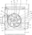
図1は本発明の一実施例であるコイン払い出し装置を概略的に示す正面からの断面端面図である。
図2は図1をサイドから見た概略的な拡大断面図である。
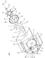
図3は図1の実施例を分解して示す概略的な斜面図である。
図1の下に示される符号11はコイン払い出し装置の基台である。
【0009】
この基台11は矩形板からなり其の三辺が下方に屈曲されて三点支持の脚に形成されている。
基台11の上面左右にはほぼ直角三角形の脚フレーム12がそれぞれ起立して固定されている。
なお脚フレーム12の一方には持ち運び用のハンドル13が取り付けられている。そして一対の脚フレーム12には大きな正方形のベース板15が傾斜して取り付けられている。
なおベース板15の適所には複数個の開孔が開設されている。
たとえばベース板15の下方部に開設されている複数個の長孔16は塵や埃などを落下させる(図3を参照)。
【0010】
またベース板15下縁部には大きなタンク17を固定するための細長い固定板2Fが配設されている。
またベース板15の上縁にはタンク17をフックで保持するための細長い支え板2Sが配置されている。
なお支え板2Sは昇降スライド可能に且つ固定可能に配設されている。
またコイン収容用のタンク17は大きな角鍋形の樹脂成形品からなっている。
そしてタンク17の下部は円筒部14に形成されていてベース板15のほぼ中央に取り付けられている。
タンク17の底部である円筒部14の内サイドにはやや大きなディスク5が回転自在に配設されている。
【0011】
なおディスク5は図3に示されるようにやや深い皿形に形成されている。
すなわちディスク5の周縁全体には起立壁5Wが形成されている。
またディスク5の周辺部全体には等間隔にコイン落し用の貫通孔5Hがそれぞれ形成されている。
当該ディスク5は中心の駆動軸6によって図1に示されるように時計方向に回転される。
なお段付きの駆動軸6は減速用のギア装置6Gを介在して電気モータ6Eよって回転される(図2を参照)。
ディスク5の上面にはヒトデ形状でリング形になるガイド体3が取り付けられている(図3を参照)。
【0012】
ガイド体3は厚味を有しており回転方向の面はスロープ面3Sに形成されている。すなわち回転するときにコインと接触するガイド体3の面がスロープ面3Sに形成されている。
なお概略リング形のガイド体3は複数個の孔3Hを介在してネジ2によりディスク5に取り付けられている(図1を参照)。
さらにディスク5の下面には概略歯車形の調整板7が取り付けられている(図3を参照)。
なお調整板7は中央で駆動軸6の段部6Sに回転可能に外装されている(図2を参照)。
【0013】
そして調整板7は複数個のネジ孔7Hを介在してネジ2によりディスク5に取り付けられている。
言い換えるとネジ2の先端部を先ずガイド体3の孔3H内にスライド自在に貫通する。
つぎに当該ネジ2の先端部をディスク5の細長孔5S内に移動自在に貫通する。この後に当該ネジ2の先端部を調整板7のネジ孔7H内に締め付けて全体を固定する。
すなわち複数個のネジ2によってガイド体3ならびにディスク5および調整板7が一体的に固着される。
【0014】
したがって貫通孔5Hと調整板7の歯部7TとによってコインCの大きさに応じた調整孔1が形成される(図1を参照)。
なお調整板7の細長い湾曲した各歯部7Tの先端部7Pは適宜に少し下方に屈曲されている。
先端部7PによってコインCが確実に押し出されるようにするためである。
調整板7の下面中央にはやや小さな円板形のスペイサ21が配置されている(図3を参照)。
スペイサ21はコインCの厚さに応じて適宜に取り替えられる。
なおスペイサ21は複数枚であっても良いことは勿論である。
【0015】
さらにスペイサ21とベース板15との間にはやや小さな長円形のスライド板22が配置されている(図3を参照)。
スライド板22はディスク5の回転をスムーズにするためのもので適宜に複数枚が使用される。
なおスライド板22ならびにスペイサ21および調整板7は駆動軸6の段部6Sに回転自在に外装されている(図2を参照)。
そしてディスク5は中央孔5Cを介在して駆動軸6に外装される。
なお中央孔5Cはディスク5が駆動軸6によって回転されるように一部直線に形成されている。
【0016】
またヒトデ・リング形のガイド体3はディスク5の上面に取り付けられることは前に述べた。
すなわちネジ2によってガイド体3ならびにディスク5および調整板7は一体的に固定されている。
したがってリング形のガイド体3の中央には駆動軸6が位置することになる。
この駆動軸6にキャップ31が被せられる。
そして当該キャップ31を介在してボルト32が駆動軸6に螺着固定される。
言い換えるとボルト32を駆動軸6に螺着してキャップ31をディスク5に押しつけて固定する。
【0017】
また円筒部14の下縁の一部が切り欠けられてコインの出口(図示略)が形成されている。
そして当該出口に連通するコインの放出路9がベース板15に形成されている。
またコインの放出路9の近くのベース板15にはコインのガイド板23が配置されている。
したがってスペイサ21の上面はガイド板23の上面よりもやや高いことは勿論である。
なおガイド板23は矩形の鉄板を平らなL形に屈曲したものである。
そしてガイド板23の元端部はベース板15の下面にボルト(図示略)を介在して移動自在に取り付けられている。
【0018】
したがってガイド板23の先端部は孔を介在してベース板15の表面にやや傾斜して突出されている。
なお前記ボルトにはスプリング(図示略)が外装されている。
したがってガイド板23は当該スプリングによってベース板15の下面に押圧されている。
ガイド板23はディスク5が正回転するときは(図1を参照)其の起立面でコインを放出路9の方向にガイドする。
そしてディスク5が逆回転するときは其の傾斜面とスプリングの作用でコインはガイド板23を乗り越えることになる。
【0019】
なお電気モータ6Eは取り付け板6Pならびににロッド6Rを介在してネジ(図示略)などで固定されている。
【実施例】
上述の本実施例はタンク17内に同一種類のコインCをバラ積み状態で収納して電気モータ6Eを駆動する。
電気モータ6Eが駆動されると図1に示されるようにディスク5が回転される。
ディスク5が回転されるとガイド体3によってコインCが貫通孔5H内にガイドされることになる(図2を参照)。
言い換えるとディスク5が回転されるとガイド体3によって貫通孔5Hの位置には複数個のコインCが常に重なる。
【0020】
すなわち貫通孔5Hの位置には複数個のコインCが常に貯留されるため後記するようにコイン払い出しは途切れない。
したがってコインが高速で払い出されても貫通孔5Hの位置にコインCが複数個あるため途切れないことになる。
また本実施例ではガイド体3をヒトデ形としたが例えば風車形にしても良いことは勿論である。
具体的に貫通孔5Hの数が三個の場合にはY形のガイド体が使用され得ることは勿論である。
加えて貫通孔5Hごとに小さなリング形のガイド体を個々に取り付けても良いことは勿論である。
【0021】
かくしてコインCが歯部7Tによって形成された調整孔1よりも小さい場合にはベース板15の上面に乗ることになる。
ベース板15上面に乗ったコインCは回転するディスク5に固定された調整板7の歯部7Tによってスライド移動されることになる。
したがって調整板7は言い換えるとコインCのスクレーパである。
スライド移動されたコインCはタンク17の円筒部4によってガイドされる。
ガイドされたコインCは円筒部4の切り欠き出口(図示略)から放出路9に送り出される。
なお調整孔1よりも大きなコインは放出路9に送り出されないことは勿論である。
【0022】
すなわち所定サイズのコインの中に大きなコインが紛れ込んでいても当該装置から放出されることはない。
なお放出路9に送り出されるコインCは計数用のローラ25をスプリング(図示略)に抗して動かす。
この計数用のローラ25の移動はセンサ(図示略)によって検出される。
ここで本実施例においてコインの大きさを変更する場合について述べる。
たとえば小さなコインにする場合には図1において調整板7の歯部7Tを反時計方向にやや移動する。
すなわち四個のネジ2を緩めて調整板7を反時計方向にやや回転し再びネジ2によってディスク5に固定する。
【0023】
実施例ではディスク5が傾斜されているが水平にしても良いことは勿論である。
言い換えると本実施例はコインをほぼ起立状態で放出するタイプの装置である。
したがって本発明はコインを水平に放出するタイプの装置にも適用できることは勿論である。
また図面のディスク5は起立壁5Wを有しているが起立壁5Wは無くても良いことは勿論である。
さらにディスク5を厚手の円板にしても良いことは勿論である。
この場合、ガイド体3がディスク5に一体的に形成されることになる。
また貫通孔5Hは適用されるコインの最大サイズを考慮して決められることは勿論である。
【0024】
また本実施例では調整板7を概略歯車形としたが円板の鋸歯形にしても良いことは勿論である。
たとえば貫通孔5Hの数が三個の場合は略三角形の調整板が使用され得ることは勿論である。
加えて各歯部7Tのみの調整板にして貫通孔5Hごとに個々に取り付けても良いことは勿論である。
【発明の効果】
以上のように本発明は簡単な構成の付加によって一台のコイン払い出し装置のみで種々のコインサイズに簡単に適用できる。
【0025】
言い換えると同一種類のコインを一個ずつ送り出す装置が本発明によると他のサイズのコインに簡単に転用できることになる。
加えて本発明はコイン払い出し用ディスクの上面に複数個のコインを重ねるための簡単なガイド体を付加している。
すなわち本発明によるとコイン落下用の貫通孔の位置に複数個のコインが常に重なることになる。
したがって本発明によるとコインが高速で払い出されても貫通孔にコインが複数個あるため途切れないことになる。
【図面の簡単な説明】
【図1】図1は本発明の一実施例であるコイン払い出し装置を概略的に示す正面からの断面端面図である。
【図2】図2は図1をサイドから見た概略的な拡大断面図である。
【図3】図3は図1の実施例を分解して示す概略的な斜面図である。
【図4】図4は従来例を示す概略的な図面である。図4の(A)は従来例の斜面図であり図4の(B)は其の従来例をサイドから見た断面図である。
【符号の説明】
C:コイン、
タンク手段・・・
14:円筒部、
17:タンク、
ディスク手段・・・
5:ディスク、
5H:貫通孔、
5S:細長孔、
調整手段・・・
7:調整板、
7H:孔、
7T:歯部、
ガイド手段・・・
3:ガイド体、
3H:孔、
3S:スロープ面。[0001]
BACKGROUND OF THE INVENTION
The present invention relates to a coin payout device for storing a plurality of small disk-shaped coins and paying out the coins.
In particular, the present invention relates to a high-speed payout device for storing coins in a stacked state and discharging the coins one by one at a high speed.
The present invention further relates to a coin payout device that can be changed according to the type of coin, that is, according to the size of the coin.
It should be noted that the term “coin” in the present specification includes a coin that is a currency. Of course, the term “coin” in the present specification includes small disks such as medals and tokens for games.
[0002]
[Prior art]
Conventionally, various devices for paying out coins are known.
For example, Japanese Patent Application No. 2-152852 filed by the present applicant discloses a coin payout device.
Japanese Patent Application No. 2-152852 has been published as Japanese Patent Application No. 6-44305. Japanese Patent Application No. 2-152852 is US Pat. No. 5,122,094. This disclosed coin payout device is schematically illustrated in FIG.
The operation of the device will now be schematically described based on FIG.
When an electric motor (not shown) in the coin payout device is driven, the central rotating
[0003]
When the
The
As the
Specifically, the stirring action is received by the
Thus, the coin in the
[0004]
The lowest coin that has entered the
The lowest coin that has been slid is forcibly sent to the
In other words, the lowest coin is moved by an elongated feed claw (not shown) formed on the lower surface of the
The lowest coin to be moved is guided by the
The
[0005]
The flange
Coins sent to the
Specifically, the coin is discharged from the
[Problems to be solved by the invention]
As described above, the conventional coin payout device is a device for delivering the same type of coins.
Therefore, the conventional coin payout device has a problem that it cannot be easily transferred to coins of other sizes.
[0006]
In addition, the conventional coin payout device has a problem that the payout efficiency of coins deteriorates when operated at high speed.
In other words, the conventional coin payout device has a problem that the efficiency of picking up coins is deteriorated when it is operated at high speed.
A first object of the present invention is to provide an apparatus that can be easily resized even if the type of coins to be paid out is changed.
A second object of the present invention is to provide an apparatus that has good coin payout efficiency even when operated at high speed.
In other words, the main object of the present invention is to improve the efficiency of picking up coins during high-speed driving by adding a simple configuration.
[0007]
[Means for Solving the Problems]
The present invention provides a tank means for storing coins in a stacked state, a disk means rotatably disposed on the inner bottom of the tank means and having a plurality of coin dropping through holes in the periphery, A base plate on which coins dropped into the through holes slide, and each tooth that is formed in a substantially gear shape and is pivotally attached to the lower surface side of the disk means so as to be concentric with the disk means, and feeds the coins on the base plate. Adjusting means wherein the portion can be moved back and forth with respect to the through-hole, and the through-hole can be formed in an adjusting hole according to the coin size by the degree of advancement and retreat of the tooth portion to the through-hole A starfish-shaped ring body having a predetermined thickness for guiding the coin to the through-hole of the disk means, and the starfish-shaped arm That it comprises a and a guide means located between the through-hole is a coin payout apparatus according to claim.
[0008]
Further, the present invention is the coin payout device characterized in that the surface of the guide means that contacts the coin is formed in a slope.
DETAILED DESCRIPTION OF THE INVENTION
Hereinafter, the present invention will be described based on its implementation with reference to the accompanying drawings.
FIG. 1 is a sectional end view from the front schematically showing a coin payout device according to an embodiment of the present invention.
FIG. 2 is a schematic enlarged sectional view of FIG. 1 viewed from the side.
FIG. 3 is a schematic oblique view showing the embodiment of FIG. 1 in an exploded manner.
[0009]
The
On the left and right sides of the upper surface of the
A
A plurality of apertures are opened at appropriate positions on the
For example, the plurality of
[0010]
An
An elongated support plate 2S for holding the
The support plate 2S is arranged to be slidable and fixable.
The
The lower portion of the
A slightly
[0011]
The
That is, a standing
Further, through
The
Note that the stepped
A
[0012]
The
The ring-shaped
Further, a substantially gear-shaped
The
[0013]
The
In other words, the tip of the
Next, the tip of the
That is, the
[0014]
Therefore, the adjustment hole 1 corresponding to the size of the coin C is formed by the through
It should be noted that the
This is to ensure that the coin C is pushed out by the
A slightly small disc-shaped
The
Of course, a plurality of
[0015]
Further, a slightly smaller
The
The
Then, the
The
[0016]
As described above, the starfish-ring
That is, the
Therefore, the
A
Then, the
In other words, the
[0017]
Further, a part of the lower edge of the
A
A
Therefore, it goes without saying that the upper surface of the
The
The base end of the
[0018]
Therefore, the front end portion of the
The bolt is externally provided with a spring (not shown).
Therefore, the
When the
When the
[0019]
The
【Example】
In the above-described embodiment, the same type of coins C are stored in the
When the
When the
In other words, when the
[0020]
That is, since a plurality of coins C are always stored at the position of the through
Therefore, even if coins are paid out at high speed, there is no interruption because there are a plurality of coins C at the positions of the through
In the present embodiment, the
Specifically, when the number of through
In addition, it goes without saying that a small ring-shaped guide body may be individually attached to each through
[0021]
Thus, when the coin C is smaller than the adjustment hole 1 formed by the
The coin C on the upper surface of the
Therefore, the
The coin C that has been slid is guided by the
The guided coin C is sent out to the
Of course, coins larger than the adjustment hole 1 are not sent out to the
[0022]
That is, even if a large coin is mixed in a coin of a predetermined size, it is not released from the device.
The coin C fed to the
The movement of the counting
Here, a case where the coin size is changed in the present embodiment will be described.
For example, when a small coin is used, the
That is, the four
[0023]
In the embodiment, the
In other words, this embodiment is a type of device that discharges coins in a substantially standing state.
Therefore, it goes without saying that the present invention can also be applied to a device of a type that discharges coins horizontally.
Further, the
Of course, the
In this case, the
Of course, the through
[0024]
In the present embodiment, the
For example, when the number of through
In addition, as a matter of course, an adjustment plate having only the
【The invention's effect】
As described above, the present invention can be easily applied to various coin sizes with only one coin payout device by adding a simple configuration.
[0025]
In other words, according to the present invention, a device that sends out coins of the same type one by one can be easily transferred to coins of other sizes.
In addition, according to the present invention, a simple guide body for stacking a plurality of coins is added to the upper surface of the coin payout disk.
That is, according to the present invention, a plurality of coins always overlap at the position of the through hole for dropping coins.
Therefore, according to the present invention, even if coins are paid out at a high speed, there are a plurality of coins in the through holes, so that there is no interruption.
[Brief description of the drawings]
FIG. 1 is a sectional end view from the front schematically showing a coin payout device according to an embodiment of the present invention.
FIG. 2 is a schematic enlarged sectional view of FIG. 1 viewed from the side.
FIG. 3 is a schematic perspective view showing the embodiment of FIG. 1 in an exploded manner.
FIG. 4 is a schematic view showing a conventional example. 4A is a perspective view of a conventional example, and FIG. 4B is a cross-sectional view of the conventional example viewed from the side.
[Explanation of symbols]
C: Coin,
Tank means ...
14: cylindrical part,
17: Tank,
Disk means ...
5: Disc,
5H: Through hole,
5S: Slotted hole,
Adjustment means ...
7: Adjustment plate,
7H: hole,
7T: Tooth part
Guide means ...
3: Guide body,
3H: hole,
3S: slope surface.
Claims (2)
前記タンク手段(17)の内底に回転可能に配置されて周辺部に複数個のコイン落下用の貫通孔(5H)をもつディスク手段(5)と、A disk means (5) rotatably disposed on the inner bottom of the tank means (17) and having a plurality of coin-dropping through holes (5H) in the periphery;
前記貫通孔(5H)に落下したコインがスライドするベース板(15)と、A base plate (15) on which a coin that has fallen into the through hole (5H) slides;
概略歯車形に形成され、前記ディスク手段(5)の下面側において当該ディスク手段(5)と同心に回動可能に取り付けられ、前記ベース板(15)上のコインを送り出す各歯部(7T)が前記貫通孔(5H)に対し進退可能であって、その歯部(7T)の前記貫通孔(5H)への進退度合によって、前記貫通孔(5H)をコインサイズに応じた調整孔(1)に形成し得るようにした調整手段(7)と、Each tooth portion (7T) which is formed in a substantially gear shape and is rotatably attached to the lower surface side of the disk means (5) so as to be concentric with the disk means (5) and feeds out coins on the base plate (15). Can be advanced and retracted with respect to the through hole (5H), and the through hole (5H) is adjusted according to the coin size (1) according to the degree of advancement and retreat of the tooth portion (7T) to the through hole (5H). Adjusting means (7) that can be formed into
前記ディスク手段(5)の上面に取り付けられた、前記コインを前記ディスク手段(5)の貫通孔(5H)にガイドするための所定の厚みを有するヒトデ形状のリング体であって、かつ前記ヒトデ形の腕は、前記貫通孔(5H)の間に位置するガイド手段(3)と、を備えていることを特徴とするコイン払い出し装置。A starfish-shaped ring body attached to the upper surface of the disk means (5) and having a predetermined thickness for guiding the coin to the through hole (5H) of the disk means (5), and the starfish A coin payout device, wherein the shaped arm comprises guide means (3) positioned between the through holes (5H).
Priority Applications (7)
| Application Number | Priority Date | Filing Date | Title |
|---|---|---|---|
| JP21569699A JP4235743B2 (en) | 1999-06-25 | 1999-06-25 | High speed coin payout device |
| GB0013196A GB2353129B (en) | 1999-06-25 | 2000-06-01 | Coin dispensing apparatus |
| US09/588,517 US6398637B1 (en) | 1999-06-25 | 2000-06-06 | High speed coin dispenser |
| TW089111467A TW432343B (en) | 1999-06-25 | 2000-06-12 | Coin disposition equipment |
| AU40894/00A AU758528B2 (en) | 1999-06-25 | 2000-06-16 | A coin dispensing apparatus |
| ES200001552A ES2170672B1 (en) | 1999-06-25 | 2000-06-21 | HIGH SPEED CURRENCY DISTRIBUTOR. |
| KR1020000034435A KR100632201B1 (en) | 1999-06-25 | 2000-06-22 | High speed coin dispensing device |
Applications Claiming Priority (1)
| Application Number | Priority Date | Filing Date | Title |
|---|---|---|---|
| JP21569699A JP4235743B2 (en) | 1999-06-25 | 1999-06-25 | High speed coin payout device |
Publications (3)
| Publication Number | Publication Date |
|---|---|
| JP2001014507A JP2001014507A (en) | 2001-01-19 |
| JP2001014507A5 JP2001014507A5 (en) | 2005-10-13 |
| JP4235743B2 true JP4235743B2 (en) | 2009-03-11 |
Family
ID=16676651
Family Applications (1)
| Application Number | Title | Priority Date | Filing Date |
|---|---|---|---|
| JP21569699A Expired - Lifetime JP4235743B2 (en) | 1999-06-25 | 1999-06-25 | High speed coin payout device |
Country Status (7)
| Country | Link |
|---|---|
| US (1) | US6398637B1 (en) |
| JP (1) | JP4235743B2 (en) |
| KR (1) | KR100632201B1 (en) |
| AU (1) | AU758528B2 (en) |
| ES (1) | ES2170672B1 (en) |
| GB (1) | GB2353129B (en) |
| TW (1) | TW432343B (en) |
Families Citing this family (20)
| Publication number | Priority date | Publication date | Assignee | Title |
|---|---|---|---|---|
| US6602125B2 (en) * | 2001-05-04 | 2003-08-05 | Coinstar, Inc. | Automatic coin input tray for a self-service coin-counting machine |
| JP4122414B2 (en) * | 2001-07-06 | 2008-07-23 | 旭精工株式会社 | Hopper rotating disc |
| WO2004010920A1 (en) * | 2002-07-29 | 2004-02-05 | Mckesson Automation Systems, Inc. | Article dispensing and counting method and device |
| US7682238B2 (en) * | 2002-09-16 | 2010-03-23 | Igt | Method and apparatus for payout in a gaming machine |
| WO2005038730A1 (en) * | 2003-10-14 | 2005-04-28 | Dun Liu | Coin dispensing apparatus |
| JP4810691B2 (en) * | 2003-12-12 | 2011-11-09 | 旭精工株式会社 | Coin hopper |
| GB2415692A (en) | 2004-06-29 | 2006-01-04 | Money Controls Ltd | Coin dispensing apparatus for large coins |
| JP4711738B2 (en) * | 2005-05-17 | 2011-06-29 | 旭精工株式会社 | Disc hopper with fraud prevention device |
| GB2431151A (en) | 2005-10-14 | 2007-04-18 | Money Controls Ltd | Coin dispensing apparatus |
| JP4844081B2 (en) * | 2005-10-19 | 2011-12-21 | 旭精工株式会社 | Coin feeding device |
| US8597758B2 (en) * | 2010-03-12 | 2013-12-03 | Euro-Pro Operating Llc | Pad for a steam appliance |
| US9036890B2 (en) | 2012-06-05 | 2015-05-19 | Outerwall Inc. | Optical coin discrimination systems and methods for use with consumer-operated kiosks and the like |
| US8967361B2 (en) | 2013-02-27 | 2015-03-03 | Outerwall Inc. | Coin counting and sorting machines |
| US9022841B2 (en) | 2013-05-08 | 2015-05-05 | Outerwall Inc. | Coin counting and/or sorting machines and associated systems and methods |
| US9235945B2 (en) | 2014-02-10 | 2016-01-12 | Outerwall Inc. | Coin input apparatuses and associated methods and systems |
| CN105427445A (en) * | 2015-12-22 | 2016-03-23 | 上海应用技术学院 | Efficient coin sorting device |
| CN107038791A (en) * | 2017-04-18 | 2017-08-11 | 天津职业技术师范大学 | A kind of coin feed mechanism |
| WO2019075111A2 (en) * | 2017-10-10 | 2019-04-18 | Crane Payment Innovations, Inc. | Coin payout apparatus |
| CN108346212A (en) * | 2018-04-02 | 2018-07-31 | 桂林航天工业学院 | A kind of coin being directed to the 5th set of coin separates and collects device and its application method |
| JP2020135414A (en) * | 2019-02-20 | 2020-08-31 | 日本金銭機械株式会社 | Coin delivery unit and coin processor using the same |
Family Cites Families (6)
| Publication number | Priority date | Publication date | Assignee | Title |
|---|---|---|---|---|
| US1524940A (en) * | 1923-03-15 | 1925-02-03 | Littell Machine Co F J | Automatic hopper feed for work pieces |
| JPH0644305B2 (en) | 1990-06-13 | 1994-06-08 | 旭精工株式会社 | Coin sending device |
| US5484334A (en) * | 1994-04-01 | 1996-01-16 | Evdokimo; Allen J. | Coin handling apparatus with coin filter and improved coin interlock |
| US5816232A (en) * | 1997-05-15 | 1998-10-06 | Cm Support, Inc. | Paintball loader having active feed mechanism |
| ES2162693T3 (en) * | 1997-09-12 | 2002-01-01 | Asahi Seiko Co Ltd | APPARATUS FOR DISPENSING CIRCULAR OBJECTS OF SHEET. |
| TW382111B (en) | 1998-05-21 | 2000-02-11 | Asahi Seiko Co Ltd | Coin accommodation funnel device |
-
1999
- 1999-06-25 JP JP21569699A patent/JP4235743B2/en not_active Expired - Lifetime
-
2000
- 2000-06-01 GB GB0013196A patent/GB2353129B/en not_active Expired - Fee Related
- 2000-06-06 US US09/588,517 patent/US6398637B1/en not_active Expired - Lifetime
- 2000-06-12 TW TW089111467A patent/TW432343B/en not_active IP Right Cessation
- 2000-06-16 AU AU40894/00A patent/AU758528B2/en not_active Ceased
- 2000-06-21 ES ES200001552A patent/ES2170672B1/en not_active Expired - Fee Related
- 2000-06-22 KR KR1020000034435A patent/KR100632201B1/en not_active IP Right Cessation
Also Published As
| Publication number | Publication date |
|---|---|
| GB2353129A (en) | 2001-02-14 |
| KR20010007481A (en) | 2001-01-26 |
| JP2001014507A (en) | 2001-01-19 |
| GB2353129B (en) | 2001-06-27 |
| AU4089400A (en) | 2001-01-04 |
| TW432343B (en) | 2001-05-01 |
| AU758528B2 (en) | 2003-03-27 |
| GB0013196D0 (en) | 2000-07-19 |
| ES2170672A1 (en) | 2002-08-01 |
| ES2170672B1 (en) | 2003-09-01 |
| US6398637B1 (en) | 2002-06-04 |
| KR100632201B1 (en) | 2006-10-11 |
Similar Documents
| Publication | Publication Date | Title |
|---|---|---|
| JP4235743B2 (en) | High speed coin payout device | |
| US3942544A (en) | Hopper payout for various coin denominations | |
| US5382024A (en) | Playing card shuffler and dispenser | |
| TW382111B (en) | Coin accommodation funnel device | |
| AU647504B2 (en) | High capacity coin hopper for a gaming machine | |
| US7775863B2 (en) | Coin dispending device and method for rapidly recycling coins | |
| JPS62117095A (en) | Coin dispensor | |
| JP3556142B2 (en) | Coin sending device | |
| US6350193B1 (en) | Coin hopper coin feeder mechanism | |
| JP4470020B2 (en) | Coin release guide for hopper device | |
| JP4002962B2 (en) | Resizable coin hopper device | |
| KR20050058970A (en) | Coin hopper | |
| JP2000172896A (en) | Coin hopper device | |
| JP3854740B2 (en) | Coin dispenser | |
| JPS6336556B2 (en) | ||
| JP2004086633A (en) | Hopper for disk | |
| JP2003123112A (en) | Coin paying-out device | |
| JPH06180777A (en) | Exit adjusting device for coin throwing out device | |
| JPH0624928Y2 (en) | Coin dispensing device | |
| JPS6227946Y2 (en) | ||
| JPS6246393A (en) | Controller for coin dispensor | |
| JP3129396B2 (en) | Disk body sending device with variable diameter | |
| JP3158270B2 (en) | Coin delivery device | |
| JPH0624927Y2 (en) | Coin sending device | |
| JP4340351B2 (en) | Pachinko machine ball dispenser |
Legal Events
| Date | Code | Title | Description |
|---|---|---|---|
| A521 | Request for written amendment filed |
Free format text: JAPANESE INTERMEDIATE CODE: A523 Effective date: 20050602 |
|
| A621 | Written request for application examination |
Free format text: JAPANESE INTERMEDIATE CODE: A621 Effective date: 20050602 |
|
| A131 | Notification of reasons for refusal |
Free format text: JAPANESE INTERMEDIATE CODE: A131 Effective date: 20080731 |
|
| A521 | Request for written amendment filed |
Free format text: JAPANESE INTERMEDIATE CODE: A523 Effective date: 20080925 |
|
| TRDD | Decision of grant or rejection written | ||
| A01 | Written decision to grant a patent or to grant a registration (utility model) |
Free format text: JAPANESE INTERMEDIATE CODE: A01 Effective date: 20081125 |
|
| A01 | Written decision to grant a patent or to grant a registration (utility model) |
Free format text: JAPANESE INTERMEDIATE CODE: A01 |
|
| A61 | First payment of annual fees (during grant procedure) |
Free format text: JAPANESE INTERMEDIATE CODE: A61 Effective date: 20081125 |
|
| R150 | Certificate of patent or registration of utility model |
Ref document number: 4235743 Country of ref document: JP Free format text: JAPANESE INTERMEDIATE CODE: R150 Free format text: JAPANESE INTERMEDIATE CODE: R150 |
|
| FPAY | Renewal fee payment (event date is renewal date of database) |
Free format text: PAYMENT UNTIL: 20111226 Year of fee payment: 3 |
|
| FPAY | Renewal fee payment (event date is renewal date of database) |
Free format text: PAYMENT UNTIL: 20111226 Year of fee payment: 3 |
|
| FPAY | Renewal fee payment (event date is renewal date of database) |
Free format text: PAYMENT UNTIL: 20121226 Year of fee payment: 4 |
|
| R250 | Receipt of annual fees |
Free format text: JAPANESE INTERMEDIATE CODE: R250 |
|
| FPAY | Renewal fee payment (event date is renewal date of database) |
Free format text: PAYMENT UNTIL: 20121226 Year of fee payment: 4 |
|
| FPAY | Renewal fee payment (event date is renewal date of database) |
Free format text: PAYMENT UNTIL: 20131226 Year of fee payment: 5 |
|
| R250 | Receipt of annual fees |
Free format text: JAPANESE INTERMEDIATE CODE: R250 |
|
| R250 | Receipt of annual fees |
Free format text: JAPANESE INTERMEDIATE CODE: R250 |
|
| R250 | Receipt of annual fees |
Free format text: JAPANESE INTERMEDIATE CODE: R250 |
|
| R250 | Receipt of annual fees |
Free format text: JAPANESE INTERMEDIATE CODE: R250 |
|
| R250 | Receipt of annual fees |
Free format text: JAPANESE INTERMEDIATE CODE: R250 |
|
| R250 | Receipt of annual fees |
Free format text: JAPANESE INTERMEDIATE CODE: R250 |
|
| R250 | Receipt of annual fees |
Free format text: JAPANESE INTERMEDIATE CODE: R250 |
|
| EXPY | Cancellation because of completion of term |