JP4234591B2 - Method and apparatus for controlling the gain level of a communication channel in a CDMA communication system - Google Patents
Method and apparatus for controlling the gain level of a communication channel in a CDMA communication system Download PDFInfo
- Publication number
- JP4234591B2 JP4234591B2 JP2003521503A JP2003521503A JP4234591B2 JP 4234591 B2 JP4234591 B2 JP 4234591B2 JP 2003521503 A JP2003521503 A JP 2003521503A JP 2003521503 A JP2003521503 A JP 2003521503A JP 4234591 B2 JP4234591 B2 JP 4234591B2
- Authority
- JP
- Japan
- Prior art keywords
- channel
- level
- communication channel
- gain
- rate
- Prior art date
- Legal status (The legal status is an assumption and is not a legal conclusion. Google has not performed a legal analysis and makes no representation as to the accuracy of the status listed.)
- Expired - Fee Related
Links
Images


Classifications
-
- H—ELECTRICITY
- H04—ELECTRIC COMMUNICATION TECHNIQUE
- H04W—WIRELESS COMMUNICATION NETWORKS
- H04W52/00—Power management, e.g. Transmission Power Control [TPC] or power classes
- H04W52/04—Transmission power control [TPC]
- H04W52/18—TPC being performed according to specific parameters
- H04W52/26—TPC being performed according to specific parameters using transmission rate or quality of service QoS [Quality of Service]
- H04W52/267—TPC being performed according to specific parameters using transmission rate or quality of service QoS [Quality of Service] taking into account the information rate
-
- H—ELECTRICITY
- H04—ELECTRIC COMMUNICATION TECHNIQUE
- H04L—TRANSMISSION OF DIGITAL INFORMATION, e.g. TELEGRAPHIC COMMUNICATION
- H04L1/00—Arrangements for detecting or preventing errors in the information received
- H04L1/0001—Systems modifying transmission characteristics according to link quality, e.g. power backoff
- H04L1/0002—Systems modifying transmission characteristics according to link quality, e.g. power backoff by adapting the transmission rate
-
- H—ELECTRICITY
- H04—ELECTRIC COMMUNICATION TECHNIQUE
- H04W—WIRELESS COMMUNICATION NETWORKS
- H04W28/00—Network traffic management; Network resource management
- H04W28/16—Central resource management; Negotiation of resources or communication parameters, e.g. negotiating bandwidth or QoS [Quality of Service]
- H04W28/18—Negotiating wireless communication parameters
- H04W28/22—Negotiating communication rate
-
- H—ELECTRICITY
- H04—ELECTRIC COMMUNICATION TECHNIQUE
- H04W—WIRELESS COMMUNICATION NETWORKS
- H04W52/00—Power management, e.g. Transmission Power Control [TPC] or power classes
- H04W52/04—Transmission power control [TPC]
- H04W52/18—TPC being performed according to specific parameters
- H04W52/28—TPC being performed according to specific parameters using user profile, e.g. mobile speed, priority or network state, e.g. standby, idle or non-transmission
- H04W52/282—TPC being performed according to specific parameters using user profile, e.g. mobile speed, priority or network state, e.g. standby, idle or non-transmission taking into account the speed of the mobile
-
- H—ELECTRICITY
- H04—ELECTRIC COMMUNICATION TECHNIQUE
- H04W—WIRELESS COMMUNICATION NETWORKS
- H04W52/00—Power management, e.g. Transmission Power Control [TPC] or power classes
- H04W52/04—Transmission power control [TPC]
- H04W52/18—TPC being performed according to specific parameters
- H04W52/24—TPC being performed according to specific parameters using SIR [Signal to Interference Ratio] or other wireless path parameters
Landscapes
- Engineering & Computer Science (AREA)
- Computer Networks & Wireless Communication (AREA)
- Signal Processing (AREA)
- Quality & Reliability (AREA)
- Mobile Radio Communication Systems (AREA)
- Transmitters (AREA)
- Cable Transmission Systems, Equalization Of Radio And Reduction Of Echo (AREA)
Description
本発明は、一般に、通信の分野に関し、特に、セルラ通信システムにおける通信に関する。 The present invention relates generally to the field of communications, and more particularly to communications in cellular communication systems.
符号分割多元接続(CDMA)通信システムにおいて、ユーザによる過度の送信は、システム容量の低減に加えて他のユーザに対する干渉の原因となり得る。従って、システムの様々なユーザによって送信される通信チャンネルのパワーレベル及び/又はデータレートは、受信端で適切な品質の受信をさせながらも、干渉レベルを制御するために且つ適切なシステム容量を維持するために制御される。通信チャンネルのパワーレベル及び/又はデータレートは、通信チャンネルの利得レベルを確立することができる。通信サービスは、ディジタル化された音声、靜又は動画像、文字メッセージ及び他の形式のデータの無線送信を含んでもよい。このような通信サービスは、種々のレベルの品質で且つ種々のレベルの移動度で、必要とされることができる。 In code division multiple access (CDMA) communication systems, excessive transmission by users can cause interference to other users in addition to reducing system capacity. Thus, the power level and / or data rate of the communication channel transmitted by various users of the system can be used to control the interference level and maintain an appropriate system capacity while allowing the reception end to receive an appropriate quality. To be controlled. The power level and / or data rate of the communication channel can establish the gain level of the communication channel. Communication services may include wireless transmission of digitized voice, speech or video, text messages and other types of data. Such communication services can be required with different levels of quality and with different levels of mobility.
他のことと同様にこの目的のために、通信システムにおける種々のレベルの移動度で、通信チャンネルのパワーレベル及び/又はデータレートの効率的な制御の必要がある。 For this purpose as well as others, there is a need for efficient control of the power level and / or data rate of the communication channel with various levels of mobility in the communication system.
[概要]
符号分割多元接続通信システムにおける、方法及び伴う装置は、種々のレベルの移動度で、通信チャンネルの利得レベルを制御することを提供する。本発明の種々の側面に従って、受信器で受信される通信チャンネルの搬送波対干渉比(C/I)の変化のレートが、決定される。C/Iの変化のレートは、通信チャンネルによって経験を積んだ移動度レベルに直接に関係することができる。そういうものとして、実施形態に従って、通信チャンネルの利得レベルは、通信チャンネルのC/Iの変化のレートに基づいてもよい。従って、通信サービスは、種々のレベルの移動度で、効率的なチャンネルデータレート及び/又はパワーレベルで提供される。
[Overview]
The method and accompanying apparatus in a code division multiple access communication system provides for controlling the gain level of a communication channel with various levels of mobility. In accordance with various aspects of the invention, the rate of change of the carrier-to-interference ratio (C / I) of the communication channel received at the receiver is determined. The rate of change of C / I can be directly related to the mobility level experienced by the communication channel. As such, according to an embodiment, the gain level of the communication channel may be based on the rate of change of the C / I of the communication channel. Thus, communication services are provided at efficient channel data rates and / or power levels with varying levels of mobility.
本発明の特徴、目的、及び利点は、同様な参照文字が全体に亘って対応して識別する図面と共に取り入れられるとき、以下に述べる詳細な説明からより明らかになるであろう。 The features, objects, and advantages of the present invention will become more apparent from the detailed description set forth below when taken in conjunction with the drawings in which like reference characters identify correspondingly throughout.
本発明の種々の実施形態は、米国通信工業会(Telecommunication Industry Association)(TIA)によって出版された種々の標準に開示され且つ記載された符号分割多元接続(CDMA)技術に従って、無線通信のためのシステムに組み込まれてもよい。このような標準は、TIA/EIA‐95標準、TIA/EIA‐IS‐2000標準、IMT‐2000標準及びWCDMA標準、この中に参照文献として組み込まれている全てを含む。この中に参照文献として組み込まれた、“TIA/EIA/IS‐856 cdma高レートパケットデータ大気インタフェース仕様書”と題する文書に記載されたデータの通信のためのシステムは、特に、本発明の種々の実施形態を組み込むことが可能である。標準の複写は、宛先:http://www.3gpp2.orgでワールドワイドウェブに接続するか、又はアメリカ合衆国、VA22201、アーリントン、ウィルソン大通2500、標準及び技術省、TIA(TIA,Standards and Technology Department,2500 Wilson Boulevard,Arlington,VA 22201,United States of America)に手紙を出すことによって入手することができる。WCDMA標準として、一般に、識別され、この中に参照文献として組み込まれた標準は、バルボンヌ‐フランス、リュシオール‐ソフィア・アンティポリ街道650、3GPP支援事務局(3GPP Support Office,650 Route des Lucioles-Sophia Antipolis,Valbonne-France)と連絡をとることによって入手することができる。 Various embodiments of the present invention may be used for wireless communications in accordance with code division multiple access (CDMA) techniques disclosed and described in various standards published by the Telecommunication Industry Association (TIA). It may be built into the system. Such standards include the TIA / EIA-95 standard, the TIA / EIA-IS-2000 standard, the IMT-2000 standard and the WCDMA standard, all of which are incorporated herein by reference. The system for communication of data described in the document entitled “TIA / EIA / IS-856 cdma High Rate Packet Data Atmosphere Interface Specification”, incorporated herein by reference, is in particular a variety of the present invention. Embodiments can be incorporated. Standard copies can be sent to: http: // www. 3gpp2. org to connect to the World Wide Web or to the United States, VA 22201, Arlington, Wilson Odori 2500, Standards and Technology Department, TIA (TIA, 2500 Wilson Boulevard, Arlington, VA 22201, United States of America) It can be obtained by sending a letter. Standards generally identified as WCDMA standards and incorporated herein as references are: Barbonne-France, Lucior-Sophia Antipoli Road 650, 3GPP Support Office, 650 Route des Lucioles-Sophia Antipolis , Valbonne-France).
一般に述べると、新規で且つ改良された方法及び伴う装置は、CDMA通信システムにおける種々のレベルの移動度で、通信チャンネルのパワーレベル及び/又はデータレートを効率的に制御することを提供する。この中に説明される1つ以上の例示的実施形態は、ディジタル無線データ通信システムという文脈の中で述べられている。この文脈の中での使用は、利点があるのだが、本発明の様々な実施形態は、様々な環境又は構成に組み込まれてもよい。一般に、この中に説明される種々のシステムは、ソフトウェア制御プロセッサ、集積回路、又は個別論理回路を使用して形成されてもよい。適用分野全体に亘って参照されてもよいデータ、手順、命令、情報、信号、シンボル、及びチップは、電圧、電流、電磁波、磁場若しくは磁粒子(magnetic fields or particles)、光場若しくは光粒子(optical fields or particles)、又はそれらの組合せによって、有利に表される。更に、各ブロック図に示されるブロックは、ハードウェア又は方法ステップを表してもよい。 Generally speaking, the new and improved methods and apparatus provide efficient control of communication channel power levels and / or data rates with various levels of mobility in a CDMA communication system. One or more exemplary embodiments described herein are set forth in the context of a digital wireless data communication system. While use within this context is advantageous, various embodiments of the invention may be incorporated into various environments or configurations. In general, the various systems described herein may be formed using software control processors, integrated circuits, or discrete logic circuits. Data, procedures, instructions, information, signals, symbols, and chips that may be referenced throughout the field of application include voltage, current, electromagnetic waves, magnetic fields or particles, light fields or particles ( optical fields or particles), or a combination thereof. Further, the blocks shown in each block diagram may represent hardware or method steps.
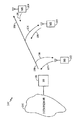
図1は、本発明の種々の実施形態を組み込みながらも、任意の符号分割多元接続(CDMA)通信システム標準に従って、動作することが可能な通信システム100の一般的なブロック図である。通信システム100は、音声、データ又はその両方の通信のためのものであってもよい。一般に、通信システム100は、移動局102‐104のような多数の移動局の間、並びに移動局102‐104と公衆交換電話及びデータ網105との間の通信リンクを与える基地局101を含む。基地局101は、移動局制御器、基地局制御器及び無線周波数トランシーバのような多数の構成要素を含んでもよい。簡単化するために、このような構成要素は、図示されていない。基地局101は、他の基地局(図示されていない)とも通信してもよい。基地局101は、順方向リンクを介して各移動局102‐104と通信する。順方向リンクは、基地局101から送信される順方向リンク信号によって維持されることができる。移動局102‐104を目標にした順方向リンク信号は、順方向リンク信号106を形成するために合計されてもよい。順方向リンク信号106を受信する移動局102‐104の各々は、そのユーザを目標にした情報を抽出するために順方向リンク信号106を復号する。
FIG. 1 is a general block diagram of a
移動局102‐104は、対応する逆方向リンクを介して基地局101と通信する。各逆方向リンクは、逆方向リンク信号107‐109のような逆方向リンク信号によって、それぞれ移動局102‐104のために維持される。移動局102‐104の各々は、基地局101へパイロットチャンネルを送信してもよい。移動局から送信されたパイロットチャンネルは、同じ移動局から送信された逆方向リンク信号によって搬送された情報を復調するために使用されてもよい。パイロットチャンネルの用途及び動作は、よく周知である。順方向及び逆方向リンクを介して通信するための送信器及び受信器は、各移動局102‐104及び基地局101に含まれる。送信器のための種々のブロック図は、IS‐95、IS‐2000、IMT‐2000、WCDMA及びIS‐856標準に示され且つ説明されている。
Mobile stations 102-104 communicate with
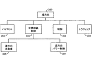
図2は、順方向リンク上の通信のために使用されることができる実施形態に従って、順方向チャンネル構造200を図示する。順方向チャンネル構造200は、パイロットチャンネル201、中間接続(medium access)チャンネル(MAC)202、トラフィックチャンネル203及び制御チャンネル204を含んでもよい。MACチャンネル202は、逆方向活動度(reverse activity)チャンネル206及び逆方向パワー制御チャンネル207を含んでもよい。逆方向活動度チャンネル206は、逆方向リンク上の活動度レベルを表示するために使用される。逆方向パワー制御チャンネル207は、そのパワーレベルで移動局が逆方向リンク上を送信することができるパワーレベルを制御するために使用される。
FIG. 2 illustrates a
図3は、実施形態に従って、逆方向リンク上の通信のために使用されてもよい逆方向チャンネル構造300を図示する。逆方向チャンネル構造300は、接続チャンネル350及びトラフィックチャンネル301を含む。接続チャンネル350は、パイロットチャンネル351及びデータチャンネル353を含む。トラフィックチャンネル301は、パイロットチャンネル304、MACチャンネル303、承認(ACK)チャンネル340及びデータチャンネル302を含む。MACチャンネル303は、逆方向リンクデータレート表示器チャンネル306及びデータレート制御チャンネル305を含む。ACKチャンネル340は、データのパケットが移動局で首尾よく復号されたかどうかを伝達するために使用される。逆方向レート表示器チャンネル306は、そのレートで移動局が目下送信しているレートを表示するために使用される。データレート制御チャンネル305は、移動局が要望し、及び/又は順方向リンク上で受信しているデータレートを表示する。
FIG. 3 illustrates a
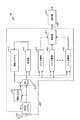
図4は、CDMA信号を処理するために使用される受信器400のブロック図を図示する。受信器400は、受信された信号によって搬送される情報を抽出するために、受信された信号を復調する。受信(Rx)標本は、RAM404に蓄積されてもよい。受信標本は、無線周波数/中間周波数(RF/IF)システム490及びアンテナシステム492によって発生させられる。アンテナシステム492は、RF信号を受信し、RF信号をRF/IFシステム490へ手渡す。RF/IFシステム490は、任意の従来のRF/IF受信器であってもよい。受信されたRF信号は、濾波され、ダウンコンバートされ且つベースバンド周波数でRX標本を形成するためにディジタル化される。標本は、多重分離器(demux)402へ供給される。demux402の出力は、検索器(searcher)ユニット406及びフィンガ(finger)要素408へ供給される。制御ユニット410は、それらに結合される。結合器(combiner)412は、復号器414をフィンガ要素408に結合する。制御ユニット410は、ソフトウェアによって制御されるマイクロプロセッサであってもよく、同一の集積回路上又は別個の集積回路上に設置されてもよい。復号器414における復号機能は、帰還との連結の有無を問わないソフト出力ビタビアルゴリズムに従ってもよい。
FIG. 4 illustrates a block diagram of a
動作中に、受信標本は、demux402へ供給される。Demux402は、標本を検索器ユニット406及びフィンガ要素408へ供給する。制御ユニット410は、検索器ユニット406からの検索結果に基づいて、様々な時間オフセットで受信された信号の復調を行うために、フィンガ要素408を形成する。復調の結果は、組合わされ、復号器414へ手渡される。復号器414は、データを復号し、復号されたデータを出力する。チャンネルの逆拡散は、受信された標本を、単一のタイミング仮説においてPN列の複素共役及び割当てられたウォルシュ関数で乗ずることによって、且つしばしば複合体及びダンプ累算器回路(integrate and dump accumulator circuit)(図示されていない)を用いて結果としての標本をディジタルに濾波することによって、行われる。このような技術は、普通、技術的に周知である。受信器400は、逆方向及び順方向リンク信号上の情報を復号するために使用されてもよい。
During operation, received samples are provided to
相互関係処理が開始される度に、検索器406及びフィンガ要素408は、タイミング仮説及び位相オフセットを試験するためのパイロットチャンネルの復調を決定するために改めて開始してもよい。検索器406若しくはフィンガ要素408又は組合わされた検索器406及びフィンガ要素408は、各受信された信号に対する搬送波対干渉比(C/I)を決定してもよい。比Eb/Iは、比C/Iと同義であり得る。比Eb/Iは、データシンボルの単位又はデータビット当りの干渉に亘る搬送波エネルギーの計量単位である。従って、C/IとEb/Iとは、若干の点で交換可能であり得る。干渉は、一般に、干渉のパワースペクトル密度及び熱雑音として規定されてもよい。
Each time the correlation process is initiated, the
受信端で適切な受信をさせながらも、干渉を制御し且つ適切なシステム容量を維持するために、システムは、各送信源からの各送信されるチャンネルの利得レベルを制御する。各チャンネルの利得レベルは、チャンネルデータレート若しくはパワーレベル又はデータレート及びパワーレベルの両方を調節することによって、調節されてもよい。チャンネルの利得レベルは、送信器での符号化された情報のデータレート及びそのパワーレベルでチャンネルが信号を介して送信されるパワーレベルに基づく。一般に、高いデータレートでのチャンネルは、干渉に打ち勝つためにより高いパワーレベルを要求する。低いデータレートでのチャンネルは、同じ干渉レベルに打ち勝つためにより少ないパワーを要求する。従って、チャンネルの利得は、パワーレベル、データレート又はパワーレベル及びデータレートの両方を調節することによって、調節されてもよい。 The system controls the gain level of each transmitted channel from each transmission source in order to control interference and maintain proper system capacity while allowing proper reception at the receiving end. The gain level of each channel may be adjusted by adjusting the channel data rate or power level or both the data rate and power level. The gain level of the channel is based on the data rate of the encoded information at the transmitter and the power level at which the channel is transmitted via the signal at that power level. In general, channels with high data rates require higher power levels to overcome interference. A channel at a lower data rate requires less power to overcome the same interference level. Thus, the gain of the channel may be adjusted by adjusting the power level, data rate or both power level and data rate.
信号のパワーレベルを制御するための種々のパワー制御方式及びチャンネルのデータレートを制御するための種々の方式は、周知である。この中に参照文献として組み込まれた種々の標準は、信号のパワーレベル及びチャンネルのデータレートを制御するための1つ以上の方式を提供する。チャンネルのパワーレベルは、2つの独立したパワー制御ループ、即ち開ループ及び閉ループによって制御されてもよい。開ループパワー制御は、送信器と適切な通信リンクを維持するための受信器の要求に基づく。データレート調節は、一般に、受信端での受信品質を可とするために、且つサービスエリア(coverage area)における干渉を制御するためである。帰還品質測定値が貧弱な受信を表示するとき、データレートは、受信の品質を向上させるために且つ干渉の効果に打ち勝つために、パワーレベルを一定に保ちながらも、低下させてもよい。データレートは、他のユーザにより高いデータレートで通信を受信させるためにも、低下させられてもよい。 Various power control schemes for controlling the power level of a signal and various schemes for controlling the data rate of a channel are well known. The various standards incorporated herein as references provide one or more schemes for controlling the power level of the signal and the data rate of the channel. The channel power level may be controlled by two independent power control loops, an open loop and a closed loop. Open loop power control is based on the receiver's requirement to maintain an appropriate communication link with the transmitter. The data rate adjustment is generally for enabling reception quality at the receiving end and controlling interference in a coverage area. When displaying a reception with poor feedback quality measurements, the data rate may be reduced while keeping the power level constant to improve the quality of the reception and to overcome the effects of interference. The data rate may also be lowered to allow other users to receive communications at a higher data rate.
この中に参照文献として組み込まれた、少なくとも1つのCDMAスペクトル拡散システム標準に従って、移動局は、符号チャンネルの特質によって出力パワーレベルを調節してもよい。移動局は、符号チャンネルパワーレベル及び逆方向パイロットチャンネルパワーレベルの間のパワーレベル比を維持し得る。その比は、符号チャンネルに使用されるデータレートに従って、設定されてもよい。一般に、表は、その値を様々なデータレートでその比にあてがう。その比は、一般に、より高いデータレートを求めて増加する。1以下の比も可能である。1に等しい比で、パワー制御ループによって設定されるようにパイロットチャンネルのパワーレベルは、符号チャンネルのパワーレベルに等しい。トラフィックチャンネル上でデータの送信中に、データレート及びトラフィックチャンネルパワーレベルは、調節され得る。一旦、差し支えないデータレートが選択されると、逆方向リンクパイロットパワーレベルに関して対応するチャンネルパワーは、トラフィックチャンネルパワーレベルを設定するために使用される。 In accordance with at least one CDMA spread spectrum system standard incorporated herein by reference, the mobile station may adjust the output power level according to the characteristics of the code channel. The mobile station may maintain a power level ratio between the code channel power level and the reverse pilot channel power level. The ratio may be set according to the data rate used for the code channel. In general, the table assigns that value to its ratio at various data rates. The ratio generally increases for higher data rates. A ratio of 1 or less is also possible. The power level of the pilot channel is equal to the power level of the code channel as set by the power control loop with a ratio equal to 1. During the transmission of data over the traffic channel, the data rate and traffic channel power level can be adjusted. Once an acceptable data rate is selected, the corresponding channel power with respect to the reverse link pilot power level is used to set the traffic channel power level.
データモードにおいて、基地局は、通信リンクを様々なデータレートで非常に多数の移動局へ提供していてもよい。例えば、順方向リンクに接続された状態の1つの移動局は、低いデータレートでデータを受信していてもよく、もう1つの移動局は、高いデータレートでデータを受信していてもよい。逆方向リンク上で、基地局は、様々な移動局から多数の逆方向リンク信号を受信していてもよい。独立の順方向リンク測定に基づいて、移動局は、基地局からの所望のデータレートを要請してもよい。所望の順方向リンクデータレートは、データレート制御(DRC)チャンネル305を介して基地局へ伝達され得る。データレートも、明白な計量に基づいて基地局によって選択されてもよい。その計量は、パワー制御サブチャンネルの送信パワーレベル及び/又は1つ以上の順方向トラフィックチャンネルの送信パワーレベルを含んでもよい。基地局は、要請されたデータレートで順方向リンクデータ転送を提供しようと試みる。
In data mode, a base station may provide a communication link to a large number of mobile stations at various data rates. For example, one mobile station connected to the forward link may be receiving data at a low data rate, and the other mobile station may be receiving data at a high data rate. On the reverse link, the base station may receive a number of reverse link signals from various mobile stations. Based on independent forward link measurements, the mobile station may request a desired data rate from the base station. The desired forward link data rate may be communicated to the base station via a data rate control (DRC)
チャンネルパワーレベル及びデータレートの調節を通じて送信器によって設定されるようにチャンネルの利得レベルは、受信端で受信される信号のC/Iレベルに基づいてもよい。受信器400は、説明したように、各受信される信号のC/Iレベルを測定してもよい。受信器は、送信器へC/I測定値を通知する。送信器は、通知されたC/Iを目標C/I閾値と比較した後、受信器での目標C/Iを維持するために、チャンネルのチャンネル利得レベルを調節する。送信器及び受信器の間の信号は、受信器で受信されている前に、種々のフェージング状態を伴ってチャンネルを通して伝播し得る。C/Iレベルは、レベルを次から次へと間断なく変化することができる。チャンネルの利得レベルを制御するために使用される制御ループは、フレーム誤りレートが適切なレベルに維持されるようなC/I目標閾値レベルを使用してもよい。C/I目標閾値は、通知する時刻及び信号の実際の送信時間の間のチャンネルにおける変動を説明するためのチャンネルC/I状態の通知をする後の少なくともある期間に亘り、適切なフレーム誤りレートを維持するために、調節されたチャンネル利得が、最低にて要求されたレベル(minimally required level)の上のレベルであるように、選択され、維持され得る。そういうものとして、チャンネル利得は、最低レベルプラスマージン(margin)に維持される。
The gain level of the channel may be based on the C / I level of the signal received at the receiving end as set by the transmitter through adjustment of the channel power level and data rate. The
C/Iレベルが測定され且つ通知されるときの時刻、及びチャンネル利得レベルが続いて選択され且つ送信器から送信されるときの時刻の間に遅延があり得る。そのように、フェージングチャンネル状態において、チャンネル利得を最低レベルを越えさせることによって、フレーム誤りレートは、殆どいつも予測的な方法で、適切なレベルに維持される。過度の利得マージンは、通信を、より低いデータレートに、より高いパワーレベルに、又は最低利得レベルに関してその両方にさせる。低いデータレートでの通信は、高いデータレートでの通信より少ないパワーを要求する。従って、データレートを変化させることによって利得マージンを加算するために、データレートは、パワーレベルを不変に保ちながらも、低下させられるかも知れない。デーレートが同じレベルに維持されるならば、チャンネル利得は、パワーレベルを増加させることによって、増加することができる。パワーレベル及びデータレートは、利得マージンに対応するより高いチャンネル利得を実現するために、変化させられてもよい。 There may be a delay between the time when the C / I level is measured and notified and the time when the channel gain level is subsequently selected and transmitted from the transmitter. As such, in fading channel conditions, the frame error rate is maintained at an appropriate level almost always in a predictive manner by causing the channel gain to exceed a minimum level. Excessive gain margins cause communications to be at lower data rates, at higher power levels, or both for the lowest gain level. Communication at low data rates requires less power than communication at high data rates. Thus, to add gain margin by changing the data rate, the data rate may be lowered while keeping the power level unchanged. If the day rate is maintained at the same level, the channel gain can be increased by increasing the power level. The power level and data rate may be varied to achieve higher channel gain corresponding to the gain margin.
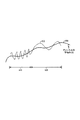
図5を参照すると、グラフ500は、チャンネルC/I状態502及び時間に関して最低の要求されたチャンネル利得(minimum required channel gain)501の例を描写する。最低の要求されたチャンネル利得501は、例えば、受信器でのチャンネルC/I状態502が送信器及び受信器の間の適切な通信リンクを維持するためには充分である。チャンネルの利得は、チャンネルC/I状態が底点にあるとき、尖頭レベルにある。時刻591で、受信器への送信のためのチャンネルの利得は、利得レベル504に設定されてもよい。時刻591で、最低利得レベル501及び選択された利得レベル504の間の過度なマージン590は、チャンネルに亘る通信を、少なくともある期間に亘って、最高フェージング状態下の適切なフレーム誤りレートにさせる。過度な利得マージンを受け入れることによって、選択された利得レベル504は、例えば、少なくともある期間550に亘って、送信器及び受信器の間の適切な通信を維持するためには充分である。過度なマージンは、チャンネルC/I状態が期間550の間に低下するならば、保護を与える。チャンネルC/I状態が期間550の間に向上するならば、こうしてより低い利得レベルを要求し、効果的な過度なマージンは、実質的には、選択された過度な利得マージン504より高くなる。そういうものとして、受信器は、最高チャンネル状態下の適切なフレーム誤りレートで受信することが可能である。
Referring to FIG. 5, a graph 500 depicts an example of a minimum required
時刻592で、過度なマージン590は、ある期間551に亘り、チャンネル状態を変化させることに対して保護をさせる。期間551は、チャンネル状態が変化しているレートにより、期間550より短い。チャンネル状態は、期間551より遅い速さで期間550の間に変化している。時刻593で、過度のマージン590は、よりずっと長い時間に亘るチャンネル状態における任意の変化に対して保護を与える。時刻593での対応するC/Iチャンネル状態は、こうして、実際の送信時間で、より低いチャンネル利得を要求するように向上している。チャンネルC/I状態が変化するレートは、送信器及び受信器が互いに離れている速さ及び/又は伝播チャンネルが変化しているレートと直接の相互関係を有する。
At time 592, an
一般的にいうと、本発明の種々の側面は、種々の状態での通信の効率的な利得制御に備える。符号分割多元接続通信システム100において、受信器400で受信される通信チャンネルの搬送波対干渉比(C/I)の変化のレートは、決定される。実施形態に従って、送信器での通信チャンネルの利得レベルは、通信チャンネルのC/Iの変化のレートに基づいてもよい。図5を参照するのだが、例えば、時刻591でのC/Iの変化のレートは、時刻592及び593での変化のレートとは異なる。C/Iの変化のレートが正であるならば、利得マージンは、実施形態に従って、通信チャンネルの送信のための最終の利得レベルを形成するために、通信チャンネルの利得レベルから減算される。C/Iの変化のレートが正であるとき、チャンネル状態は、向上している。例えば、C/Iの変化のレートは、時刻593で正である。C/Iは、時刻593では増加している。従って、時刻593で、実施形態に従って、利得マージンは、通信チャンネルの送信のための最終の利得レベルを形成するために、通信チャンネルの利得レベルから減算される。
Generally speaking, various aspects of the present invention provide for efficient gain control of communications in various states. In the code division multiple
利得マージンの大きさは、実施形態に従って、C/Iの変化のレートの大きさに比例的に対応するかも知れない。C/Iの正の変化のレートが大きいならば、チャンネル状態は、C/Iの正の変化のレートが小さいときよりも、より速いレートで向上している。従って、予測的な方法で、チャンネル状態は、C/Iの大きな正の変化のレートに伴ってチャンネルにおいて推定されたものよりも、遥かに小さい最終の利得レベルを要求する。そういうものとして、利得マージンの大きさは、C/Iの小さな正の変化のレートに伴うチャンネル状態においてよりも、C/Iの大きな正の変化のレートに伴うチャンネル状態において、より大きくなり得る。利得マージンを減算するこの効果を目的として、通信チャンネルのデータレートは、実施形態に従って、増加することができる。データレートは、C/Iの変化のレートが正であるとき、チャンネル状態が向上しているので、増加することができる。従って、予測的な方法で、チャンネルは、より高いデータレートで通信リンクを維持することが可能である。通信チャンネルのバワーレベルは、利得マージンを減算することの効果を目的として、実施形態に従って、減少させられてもよい。パワーレベルは、C/Iの変化のレートが正であるとき、チャンネル状態が向上しているので、減少され得る。利得マージンを減算する効果を目的として、実施形態に従って、パワーレベルは、減少させられることができ、且つデータレートは、同時に、増加されることができる。従って、予測的な方法で、チャンネルは、同じデータレートで且つより低いパワーレベルで、通信リンクを維持することが可能である。 The magnitude of the gain margin may correspond proportionally to the magnitude of the rate of change of C / I, according to an embodiment. If the rate of positive change in C / I is large, the channel condition improves at a faster rate than when the rate of positive change in C / I is small. Thus, in a predictive manner, the channel conditions require a final gain level that is much smaller than that estimated in the channel with a large positive rate of change in C / I. As such, the magnitude of the gain margin can be greater in the channel condition associated with a large positive change rate of C / I than in the channel condition associated with a small positive change rate of C / I. For this effect of subtracting the gain margin, the data rate of the communication channel can be increased according to the embodiment. The data rate can be increased when the rate of change of C / I is positive because the channel condition is improved. Thus, in a predictive manner, the channel can maintain the communication link at a higher data rate. The power level of the communication channel may be reduced according to an embodiment for the purpose of subtracting the gain margin. The power level can be reduced when the rate of change of C / I is positive because the channel condition is improving. For the effect of subtracting the gain margin, according to an embodiment, the power level can be reduced and the data rate can be increased simultaneously. Thus, in a predictive manner, the channel can maintain the communication link at the same data rate and at a lower power level.
C/Iの変化のレートが負であるならば、利得マージンは、実施形態に従って、通信チャンネルの送信のための最終の利得レベルを形成するために通信チャンネルの利得レベルに加算される。C/Iの変化のレートが負であるとき、チャンネル状態は劣化している。例えば、C/Iの変化のレートは、時刻591及び592で負である。C/Iは、時刻591及び592で減少している。従って、実施形態に従って、利得マージンは、時刻591及び592で通信チャンネルの送信のための最終の利得レベルを形成するために通信チャンネルの利得レベルに加算される。
If the rate of change of C / I is negative, the gain margin is added to the communication channel gain level to form the final gain level for transmission of the communication channel, according to an embodiment. When the rate of change of C / I is negative, the channel state is degraded. For example, the rate of change of C / I is negative at
利得マージンの大きさは、実施形態に従って、C/Iの変化のレートの大きさに比例的に対応することができる。C/Iの負の変化のレートが大きいならば、チャンネル状態は、C/Iの負の変化のレートが小さいときよりも、より速いレートで劣化している。従って、予測的な方法で、チャンネル状態は、C/Iの大きな負の変化のレートに伴ってチャンネルにおいて推定されたものよりも、遥かに大きい最終の利得レベルを要求する。そのように、利得マージンの大きさは、C/Iの小さな負の変化のレートに伴うチャンネル状態においてよりも、C/Iの大きな負の変化のレートに伴うチャンネル状態において、より大きくなり得る。時刻591での負の変化のレートは、時刻592での負の変化のレートより小さい。従って、時刻591での利得マージンの大きさは、実施形態に従って、時刻592での利得マージンの大きさより小さい。
The magnitude of the gain margin can proportionally correspond to the magnitude of the rate of change of C / I according to the embodiment. If the rate of negative change in C / I is large, the channel condition is degraded at a faster rate than when the rate of negative change in C / I is small. Thus, in a predictive manner, the channel condition requires a final gain level that is much greater than that estimated in the channel with a large negative rate of change in C / I. As such, the magnitude of the gain margin can be greater in the channel conditions associated with a large negative change rate of C / I than in the channel conditions associated with a small negative change rate of C / I. The rate of negative change at
利得マージンを加算することの効果を目的として、通信チャンネルのデータレートを、実施形態に従って、減少することができる。C/Iの変化のレートが負であるとき、チャンネル状態が劣化しているので、データレートを減少することができる。従って、予測的な方法で、チャンネルは、フレーム消去を回避しながらも、より低いデータレートで通信リンクを維持することが可能である。更に、利得マージンを加算する効果を目的として、通信チャンネルのバワーレベルを、実施形態に従って、増加することができる。C/Iの変化のレートが負であるとき、チャンネル状態が劣化しているので、パワーレベルを増加することができる。利得マージンを加算することの効果を目的として、データレートを、減少することができ、且つパワーレベルは、同時に、減少することができる。従って、予測的な方法で、チャンネルは、同じデータレートで且つより高いパワーレベルで、通信リンクを維持することが可能である。 For the purpose of adding the gain margin, the data rate of the communication channel can be reduced according to the embodiment. When the rate of change in C / I is negative, the data rate can be reduced because the channel condition is degraded. Thus, in a predictive manner, the channel can maintain the communication link at a lower data rate while avoiding frame erasure. Furthermore, the power level of the communication channel can be increased according to the embodiment for the purpose of adding a gain margin. When the rate of change of C / I is negative, the channel level is degraded, so the power level can be increased. For the purpose of adding gain margins, the data rate can be reduced and the power level can be reduced simultaneously. Thus, in a predictive manner, the channel can maintain the communication link at the same data rate and at a higher power level.
送信器及び受信器の間のチャンネル状態は、動的であり得る。速いフェージング状態は、高移動度状態と呼ばれてもよく、且つ遅いフェージング状態は、低移動度状態と呼ばれてもよい。図6を参照すると、チャンネルのC/I状態の例が示されている。例えば、時間帯610で、チャンネルは、速いフェージング状態にあってもよく、且つ時間帯620で、遅いフェージング状態にあってもよい。平均のC/I601は、ある期間に亘るチャンネルの平均のC/Iである。チャンネルの瞬間のC/I602は、様々な時刻で平均のC/I601と交差する。瞬間のC/I602が平均のC/I601と交差する回数は、時間帯620に対応する遅いフェージング状態よりも、時間帯610に対応する速いフェージング状態における方が高い。瞬間のC/I602が平均のC/I601と交差する回数は、通信システム100における通信チャンネルの移動度レベルに比例することができる。従って、受信器400の移動度レベルは、瞬間のC/I602が平均のC/I601と交差する回数を決定することによって、決定され得る。
The channel condition between the transmitter and receiver can be dynamic. A fast fading state may be referred to as a high mobility state, and a slow fading state may be referred to as a low mobility state. Referring to FIG. 6, an example of the C / I state of the channel is shown. For example, in
実施形態に従って、通信システム100における通信チャンネルの移動度レベルは、チャンネルの瞬間のC/Iがチャンネルの平均のC/I601と交差する回数を決定することによって、決定され得る。移動度レベルは、移動度閾値と比較され得る。移動度閾値は、低移動度レベルに対応することができる。移動度レベルが低移動度閾値に適合するならば、通信システム100における送信器及び受信器400の間の通信チャンネルの利得レベルは、実施形態に従って、C/Iの変化のレートに基くことができる。移動度レベルが低移動度閾値の下にあるならば、チャンネル状態は、低移動度状態に対応する。低移動度状態で、チャンネル状態は、ゆっくり変化することができ、こうして、実施形態に従って、予測的な方法で、チャンネルの利得レベルをC/Iの変化のレートに基づかせる。
According to an embodiment, the mobility level of the communication channel in the
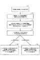
図7を参照すると、流れ図700は、本発明の種々の側面を実施するために追従することができる。ステップ701で、受信器の移動度レベルは、決定されてもよい。移動度レベルは、ステップ702で、低移動度閾値と比較される。低移動度閾値は、低移動度レベル状態に対応することができる。移動度レベルが低移動度閾値より小さいならば、チャンネルC/Iが変化しているレートは、ステップ703で、決定される。ステップ704で、受信器400における制御システム410のような制御器は、C/Iの変化のレートが正であるか負であるかを決定してもよい。ステップ705で、変化のレートが正であるならば、利得マージンは、実施形態に従って、チャンネルの最低の利得から減算される。ステップ706で、変化のレートが負であるならば、利得マージンは、実施形態に従って、チャンネルの最低の利得に加算される。チャンネルは、調節された利得レベルで送信されることができる。
Referring to FIG. 7, a flowchart 700 can be followed to implement various aspects of the present invention. In
技術的に熟達した人達は、この中に開示された実施形態に関連して説明された、種々の実例となる論理ブロック、モジュール、回路、及びアルゴリズムステップが、電子的ハードウェア、コンピュータソフトウェア、又は両方の組合せとして実施できることを、更に正当に評価する。このハードウェア及びソフトウェアの互換性を明確に図示するために、種々の実例となる構成要素、ブロック、モジュール、回路、及びステップは、その機能性の点から一般的に前に説明した。このような機能性がハードウェア又はソフトウェアとして実施されるかどうかは、全体的なシステムに課せられる特定の適用及び設計の制約条件に依存する。熟達した技術者は、各特定の適用範囲に対して種々の方法で説明された機能性を実施し得るが、このような実施決定は、本発明の範囲から離脱して生じさせるものと解釈されるべきではない。 Those skilled in the art will recognize that the various illustrative logic blocks, modules, circuits, and algorithm steps described in connection with the embodiments disclosed herein are electronic hardware, computer software, or More justify that it can be implemented as a combination of both. To clearly illustrate this hardware and software compatibility, various illustrative components, blocks, modules, circuits, and steps have been described above generally in terms of their functionality. Whether such functionality is implemented as hardware or software depends upon the particular application and design constraints imposed on the overall system. A skilled engineer may implement the functionality described in various ways for each particular scope, but such implementation decisions are to be construed as departing from the scope of the present invention. Should not.
この中に開示された実施形態に関連して説明された、種々の実例となる論理ブロック、モジュール、及び回路は、汎用プロセッサ、ディジタル信号プロセッサ(DSP)、特定用途集積回路(ASIC)、現場プログラム可能ゲートアレー(FPGA)若しくは他のプログラム可能論理装置、個別ゲート若しくはトランジスタ論理回路、個別ハードウェア構成要素、又はこの中に説明された機能を行うために設計されたそれらの任意の組合せ、を用いて実施され又は行われることができる。汎用プロセッサは、マイクロプロセッサであってもよいが、代案として、プロセッサは、任意の従来のプロセッサ、制御器、マイクロコントローラ、又は状態マシーンであってもよい。プロセッサはまた、計算装置の組合せ、例えば、DSP及びマイクロプロセッサの組合せ、複数のマイクロプロセッサ、DSP中核と組合せた1つ以上のマイクロプロセッサ、又は任意の他のこのような構成であってもよい。 The various illustrative logic blocks, modules, and circuits described in connection with the embodiments disclosed herein are general purpose processors, digital signal processors (DSPs), application specific integrated circuits (ASICs), field programs. Using a programmable gate array (FPGA) or other programmable logic device, individual gate or transistor logic, individual hardware components, or any combination thereof designed to perform the functions described herein Can be implemented or performed. A general purpose processor may be a microprocessor, but in the alternative, the processor may be any conventional processor, controller, microcontroller, or state machine. The processor may also be a combination of computing devices, eg, a DSP and microprocessor combination, multiple microprocessors, one or more microprocessors in combination with a DSP core, or any other such configuration.
この中に説明された実施形態に関連して説明した方法又はアルゴリズムのステップは、ハードウェアに、プロセッサによって実行されるソフトウェアモジュールに、又はその組合せに、直接に具現化され得る。ソフトウェアモジュールは、RAMメモリ、フラッシュメモリ、ROMメモリ、EPROMメモリ、EEPROMメモリ、レジスタ、ハードディスク、着脱可能ディスク、CD‐ROM、又は技術的に周知の任意の他の形式の蓄積媒体に存在してもよい。例示的蓄積媒体は、プロセッサが蓄積媒体から情報を読み出し、蓄積媒体へ情報を書き込むことができるような、プロセッサに結合される。代案として、蓄積媒体は、プロセッサに内蔵のものでもよい。プロセッサ及び蓄積媒体は、ASICに存在してもよい。ASICは、ユーザ端末に存在してもよい。代案として、プロセッサ及び蓄積媒体は、ユーザ端末に個別構成要素として存在してもよい。 The method or algorithm steps described in connection with the embodiments described herein may be implemented directly in hardware, in software modules executed by a processor, or in a combination thereof. A software module may reside in RAM memory, flash memory, ROM memory, EPROM memory, EEPROM memory, registers, hard disk, removable disk, CD-ROM, or any other form of storage medium known in the art. Good. An exemplary storage medium is coupled to the processor such that the processor can read information from, and write information to, the storage medium. In the alternative, the storage medium may be internal to the processor. The processor and storage medium may reside in an ASIC. The ASIC may exist in the user terminal. In the alternative, the processor and the storage medium may reside as discrete components in a user terminal.
先の好ましい実施形態の説明は、技術的に熟達した任意の人が、本発明を製品化し又は使用することが可能になるように提供される。これらの実施形態への種々の変更は、技術的に熟達した人達には、即座に明白であり、且つこの中に規定された包括的原理は、創意に富む能力を使用しなくても他の実施形態に適用され得る。このように、本発明は、この中に示された実施形態に限定されるように意図されるものではなく、この中に開示された原理及び新規な特徴とは矛盾しない最も広い範囲と一致するものである。 The previous description of the preferred embodiment is provided to enable any person skilled in the art to make or use the present invention. Various changes to these embodiments will be readily apparent to those skilled in the art, and the generic principles defined therein may be useful without the use of inventive capabilities. It can be applied to the embodiment. Thus, the present invention is not intended to be limited to the embodiments shown herein, but is consistent with the widest scope consistent with the principles and novel features disclosed therein. Is.
Claims (10)
前記方法は、The method
受信された通信チャンネルの搬送波対干渉比(C/I)を決定することと、Determining a carrier to interference ratio (C / I) of a received communication channel;
前記受信された通信チャネルの前記C/Iの変化のレートを決定することと、Determining a rate of change of the C / I of the received communication channel;
前記決定されたC/Iに基づいて、前記通信チャンネルの最小利得レベルを決定することと、Determining a minimum gain level of the communication channel based on the determined C / I;
前記C/Iの前記変化のレートに基づいて、前記通信チャンネルの利得マージンを決定することと、Determining a gain margin for the communication channel based on the rate of change of the C / I;
前記通信チャンネルを介した受信機へのデータ送信のために、前記最小利得レベルと前記利得マージンとに基づいて、前記通信チャンネルの利得レベルを決定することと、Determining a gain level of the communication channel based on the minimum gain level and the gain margin for data transmission to a receiver via the communication channel;
を備える。Is provided.
前記決定された移動度レベルが移動度閾値に適合するか否かを決定することと、Determining whether the determined mobility level meets a mobility threshold;
をさらに備え、Further comprising
前記通信チャンネルの前記利得マージンの決定は、前記決定された移動度レベルが前記移動度閾値に適合するか否かに基づく、The determination of the gain margin of the communication channel is based on whether the determined mobility level meets the mobility threshold.
請求項1に記載の方法。The method of claim 1.
前記装置はコントローラを備え、The apparatus comprises a controller;
前記コントローラは、The controller is
受信された通信チャンネルの搬送波対干渉比(C/I)を決定し、Determining the carrier-to-interference ratio (C / I) of the received communication channel;
前記受信された通信チャネルの前記C/Iの変化のレートを決定し、Determining the rate of change of the C / I of the received communication channel;
前記決定されたC/Iに基づいて、前記通信チャンネルの最小利得レベルを決定し、Determining a minimum gain level of the communication channel based on the determined C / I;
前記C/Iの前記変化のレートに基づいて、前記通信チャンネルの利得マージンを決定し、Determining a gain margin of the communication channel based on the rate of change of the C / I;
前記通信チャンネルを介した受信機へのデータ送信のために、前記最小利得レベルと前記利得マージンとに基づいて、前記通信チャンネルの利得レベルを決定するように構成される。It is configured to determine a gain level of the communication channel based on the minimum gain level and the gain margin for data transmission to the receiver via the communication channel.
前記通信チャンネルの移動度レベルを決定し、Determining the mobility level of the communication channel;
前記決定された移動度レベルが移動度閾値に適合するか否かを決定するように構成され、Configured to determine whether the determined mobility level meets a mobility threshold;
前記通信チャンネルの前記利得マージンの決定は、前記決定された移動度レベルが前記移動度閾値に適合するか否かに基づく、The determination of the gain margin of the communication channel is based on whether the determined mobility level meets the mobility threshold.
請求項6に記載の装置。The apparatus according to claim 6.
Applications Claiming Priority (2)
| Application Number | Priority Date | Filing Date | Title |
|---|---|---|---|
| US09/928,578 US7139304B2 (en) | 2001-08-10 | 2001-08-10 | Method and apparatus for controlling gain level of a communication channel in a CDMA communication system |
| PCT/US2002/025467 WO2003017526A1 (en) | 2001-08-10 | 2002-08-08 | Method and apparatus for controlling gain level of a communication channel in a cdma communication system |
Publications (2)
| Publication Number | Publication Date |
|---|---|
| JP2005500734A JP2005500734A (en) | 2005-01-06 |
| JP4234591B2 true JP4234591B2 (en) | 2009-03-04 |
Family
ID=25456463
Family Applications (1)
| Application Number | Title | Priority Date | Filing Date |
|---|---|---|---|
| JP2003521503A Expired - Fee Related JP4234591B2 (en) | 2001-08-10 | 2002-08-08 | Method and apparatus for controlling the gain level of a communication channel in a CDMA communication system |
Country Status (9)
| Country | Link |
|---|---|
| US (2) | US7139304B2 (en) |
| EP (1) | EP1415412B1 (en) |
| JP (1) | JP4234591B2 (en) |
| KR (1) | KR100952862B1 (en) |
| CN (1) | CN1539211B (en) |
| AT (1) | ATE490662T1 (en) |
| DE (1) | DE60238488D1 (en) |
| TW (1) | TWI249299B (en) |
| WO (1) | WO2003017526A1 (en) |
Cited By (1)
| Publication number | Priority date | Publication date | Assignee | Title |
|---|---|---|---|---|
| US8475149B2 (en) | 2008-04-07 | 2013-07-02 | Mitsubishi Electric Corporation | Scroll fluid machine having multiple discharge ports |
Families Citing this family (13)
| Publication number | Priority date | Publication date | Assignee | Title |
|---|---|---|---|---|
| US7139304B2 (en) * | 2001-08-10 | 2006-11-21 | Qualcomm Incorporated | Method and apparatus for controlling gain level of a communication channel in a CDMA communication system |
| US7299402B2 (en) * | 2003-02-14 | 2007-11-20 | Telefonaktiebolaget Lm Ericsson (Publ) | Power control for reverse packet data channel in CDMA systems |
| US8432803B2 (en) | 2004-07-21 | 2013-04-30 | Qualcomm Incorporated | Method of providing a gap indication during a sticky assignment |
| US8477710B2 (en) * | 2004-07-21 | 2013-07-02 | Qualcomm Incorporated | Method of providing a gap indication during a sticky assignment |
| US8891349B2 (en) | 2004-07-23 | 2014-11-18 | Qualcomm Incorporated | Method of optimizing portions of a frame |
| CN1728579A (en) * | 2004-07-30 | 2006-02-01 | 俞隽 | Communication network system and method syncretic configured from wireless mobile comunication and wired discontinuous mobile communication |
| EP1859590B1 (en) * | 2004-11-15 | 2012-03-14 | Koninklijke Philips Electronics N.V. | Method and apparatus for detecting high-mobility state of mobile terminal and related device |
| US8537760B2 (en) * | 2004-12-17 | 2013-09-17 | Samsung Electronics Co., Ltd | Method and system for dynamic hybrid multiple access in an OFDM-based wireless network |
| US7672286B2 (en) * | 2005-04-18 | 2010-03-02 | Via Telecom Co., Ltd. | Reverse-link structure for a multi-carrier communication system |
| US20060252451A1 (en) * | 2005-05-06 | 2006-11-09 | Cho Sung R | Transmission power control device and method |
| US20080051126A1 (en) * | 2006-08-22 | 2008-02-28 | Shirish Nagaraj | Method for allocating transmit power in a wireless communication system |
| CN101494516B (en) * | 2008-01-22 | 2011-10-26 | 中兴通讯股份有限公司 | Method and apparatus for self-adapting feedback of down channel quality |
| US8983397B2 (en) * | 2008-10-10 | 2015-03-17 | Qualcomm Incorporated | Method and apparatus for channel feedback by multiple description coding in a wireless communication system |
Family Cites Families (10)
| Publication number | Priority date | Publication date | Assignee | Title |
|---|---|---|---|---|
| US5873028A (en) * | 1994-10-24 | 1999-02-16 | Ntt Mobile Communications Network Inc. | Transmission power control apparatus and method in a mobile communication system |
| US5793805A (en) * | 1995-12-14 | 1998-08-11 | Motorola, Inc. | Signal measurement system and method for measuring the signal quality of a received radio frequency signal |
| WO1999007105A2 (en) * | 1997-08-01 | 1999-02-11 | Salbu Research And Development (Proprietary) Limited | Power adaptation in a multi-station network |
| US6400929B1 (en) * | 1998-04-17 | 2002-06-04 | Matsushita Electric Industrial Co., Ltd. | Radio communication device and method of controlling transmission rate |
| US6490460B1 (en) | 1998-12-01 | 2002-12-03 | Qualcomm Incorporated | Forward and reverse link power control using position and mobility information |
| JP3961828B2 (en) | 1999-09-22 | 2007-08-22 | 富士通株式会社 | Transmission power control device |
| GB0008020D0 (en) * | 2000-03-31 | 2000-05-17 | Koninkl Philips Electronics Nv | Radio comunication system |
| US6735449B2 (en) * | 2000-12-28 | 2004-05-11 | Nokia Corporation | Apparatus, and an associated method, for facilitating power control in a communication system |
| US7801544B2 (en) * | 2001-06-29 | 2010-09-21 | Koninklijke Philips Electronics N.V. | Noise margin information for power control and link adaptation in IEEE 802.11h WLAN |
| US7139304B2 (en) * | 2001-08-10 | 2006-11-21 | Qualcomm Incorporated | Method and apparatus for controlling gain level of a communication channel in a CDMA communication system |
-
2001
- 2001-08-10 US US09/928,578 patent/US7139304B2/en not_active Expired - Fee Related
-
2002
- 2002-08-08 WO PCT/US2002/025467 patent/WO2003017526A1/en not_active Ceased
- 2002-08-08 CN CN02815531.9A patent/CN1539211B/en not_active Expired - Fee Related
- 2002-08-08 EP EP02757072A patent/EP1415412B1/en not_active Expired - Lifetime
- 2002-08-08 KR KR1020047001941A patent/KR100952862B1/en not_active Expired - Fee Related
- 2002-08-08 AT AT02757072T patent/ATE490662T1/en not_active IP Right Cessation
- 2002-08-08 JP JP2003521503A patent/JP4234591B2/en not_active Expired - Fee Related
- 2002-08-08 DE DE60238488T patent/DE60238488D1/en not_active Expired - Lifetime
- 2002-08-09 TW TW091118008A patent/TWI249299B/en active
-
2006
- 2006-10-05 US US11/544,233 patent/US7769079B2/en not_active Expired - Fee Related
Cited By (1)
| Publication number | Priority date | Publication date | Assignee | Title |
|---|---|---|---|---|
| US8475149B2 (en) | 2008-04-07 | 2013-07-02 | Mitsubishi Electric Corporation | Scroll fluid machine having multiple discharge ports |
Also Published As
| Publication number | Publication date |
|---|---|
| ATE490662T1 (en) | 2010-12-15 |
| CN1539211B (en) | 2010-11-10 |
| CN1539211A (en) | 2004-10-20 |
| WO2003017526A1 (en) | 2003-02-27 |
| EP1415412A1 (en) | 2004-05-06 |
| US20030031142A1 (en) | 2003-02-13 |
| US20070025427A1 (en) | 2007-02-01 |
| KR20040017855A (en) | 2004-02-27 |
| TWI249299B (en) | 2006-02-11 |
| US7139304B2 (en) | 2006-11-21 |
| EP1415412B1 (en) | 2010-12-01 |
| KR100952862B1 (en) | 2010-04-13 |
| US7769079B2 (en) | 2010-08-03 |
| JP2005500734A (en) | 2005-01-06 |
| DE60238488D1 (en) | 2011-01-13 |
Similar Documents
| Publication | Publication Date | Title |
|---|---|---|
| JP3950056B2 (en) | Power control method and apparatus in communication system | |
| AU2002312547B2 (en) | Method and apparatus for controlling gain level of a supplemental channel in a CDMA communication system | |
| CA2527862C (en) | Method and apparatus for communications of data in a communication system | |
| AU2002312547A1 (en) | Method and apparatus for controlling gain level of a supplemental channel in a CDMA communication system | |
| JP4234591B2 (en) | Method and apparatus for controlling the gain level of a communication channel in a CDMA communication system | |
| JP4546088B2 (en) | Power control of downlink shared channel | |
| JP4846970B2 (en) | Method and apparatus for controlling call requests in a communication system | |
| HK1067250A (en) | Method and apparatus for controlling gain level of a communication channel in a cdma communication system | |
| HK1067814B (en) | Method and apparatus for controlling gain level of a supplemental channel in a cdma communication system | |
| HK1068077B (en) | Method for power control in a communication system |
Legal Events
| Date | Code | Title | Description |
|---|---|---|---|
| A621 | Written request for application examination |
Free format text: JAPANESE INTERMEDIATE CODE: A621 Effective date: 20050808 |
|
| A131 | Notification of reasons for refusal |
Free format text: JAPANESE INTERMEDIATE CODE: A131 Effective date: 20080527 |
|
| A601 | Written request for extension of time |
Free format text: JAPANESE INTERMEDIATE CODE: A601 Effective date: 20080822 |
|
| A602 | Written permission of extension of time |
Free format text: JAPANESE INTERMEDIATE CODE: A602 Effective date: 20080829 |
|
| A521 | Request for written amendment filed |
Free format text: JAPANESE INTERMEDIATE CODE: A523 Effective date: 20080926 |
|
| TRDD | Decision of grant or rejection written | ||
| A01 | Written decision to grant a patent or to grant a registration (utility model) |
Free format text: JAPANESE INTERMEDIATE CODE: A01 Effective date: 20081111 |
|
| A01 | Written decision to grant a patent or to grant a registration (utility model) |
Free format text: JAPANESE INTERMEDIATE CODE: A01 |
|
| A61 | First payment of annual fees (during grant procedure) |
Free format text: JAPANESE INTERMEDIATE CODE: A61 Effective date: 20081211 |
|
| FPAY | Renewal fee payment (event date is renewal date of database) |
Free format text: PAYMENT UNTIL: 20111219 Year of fee payment: 3 |
|
| R150 | Certificate of patent or registration of utility model |
Free format text: JAPANESE INTERMEDIATE CODE: R150 |
|
| LAPS | Cancellation because of no payment of annual fees |