JP4232041B2 - Sliding valve - Google Patents
Sliding valve Download PDFInfo
- Publication number
- JP4232041B2 JP4232041B2 JP2004562553A JP2004562553A JP4232041B2 JP 4232041 B2 JP4232041 B2 JP 4232041B2 JP 2004562553 A JP2004562553 A JP 2004562553A JP 2004562553 A JP2004562553 A JP 2004562553A JP 4232041 B2 JP4232041 B2 JP 4232041B2
- Authority
- JP
- Japan
- Prior art keywords
- control
- sliding valve
- sliding
- valve according
- sliding sleeve
- Prior art date
- Legal status (The legal status is an assumption and is not a legal conclusion. Google has not performed a legal analysis and makes no representation as to the accuracy of the status listed.)
- Expired - Fee Related
Links
Images

Classifications
-
- F—MECHANICAL ENGINEERING; LIGHTING; HEATING; WEAPONS; BLASTING
- F02—COMBUSTION ENGINES; HOT-GAS OR COMBUSTION-PRODUCT ENGINE PLANTS
- F02M—SUPPLYING COMBUSTION ENGINES IN GENERAL WITH COMBUSTIBLE MIXTURES OR CONSTITUENTS THEREOF
- F02M61/00—Fuel-injectors not provided for in groups F02M39/00 - F02M57/00 or F02M67/00
- F02M61/16—Details not provided for in, or of interest apart from, the apparatus of groups F02M61/02 - F02M61/14
- F02M61/18—Injection nozzles, e.g. having valve seats; Details of valve member seated ends, not otherwise provided for
-
- F—MECHANICAL ENGINEERING; LIGHTING; HEATING; WEAPONS; BLASTING
- F02—COMBUSTION ENGINES; HOT-GAS OR COMBUSTION-PRODUCT ENGINE PLANTS
- F02M—SUPPLYING COMBUSTION ENGINES IN GENERAL WITH COMBUSTIBLE MIXTURES OR CONSTITUENTS THEREOF
- F02M61/00—Fuel-injectors not provided for in groups F02M39/00 - F02M57/00 or F02M67/00
- F02M61/04—Fuel-injectors not provided for in groups F02M39/00 - F02M57/00 or F02M67/00 having valves, e.g. having a plurality of valves in series
- F02M61/042—The valves being provided with fuel passages
-
- F—MECHANICAL ENGINEERING; LIGHTING; HEATING; WEAPONS; BLASTING
- F02—COMBUSTION ENGINES; HOT-GAS OR COMBUSTION-PRODUCT ENGINE PLANTS
- F02M—SUPPLYING COMBUSTION ENGINES IN GENERAL WITH COMBUSTIBLE MIXTURES OR CONSTITUENTS THEREOF
- F02M63/00—Other fuel-injection apparatus having pertinent characteristics not provided for in groups F02M39/00 - F02M57/00 or F02M67/00; Details, component parts, or accessories of fuel-injection apparatus, not provided for in, or of interest apart from, the apparatus of groups F02M39/00 - F02M61/00 or F02M67/00; Combination of fuel pump with other devices, e.g. lubricating oil pump
- F02M63/0012—Valves
- F02M63/007—Details not provided for in, or of interest apart from, the apparatus of the groups F02M63/0014 - F02M63/0059
- F02M63/0078—Valve member details, e.g. special shape, hollow or fuel passages in the valve member
- F02M63/008—Hollow valve members, e.g. members internally guided
-
- F—MECHANICAL ENGINEERING; LIGHTING; HEATING; WEAPONS; BLASTING
- F02—COMBUSTION ENGINES; HOT-GAS OR COMBUSTION-PRODUCT ENGINE PLANTS
- F02M—SUPPLYING COMBUSTION ENGINES IN GENERAL WITH COMBUSTIBLE MIXTURES OR CONSTITUENTS THEREOF
- F02M51/00—Fuel-injection apparatus characterised by being operated electrically
- F02M51/06—Injectors peculiar thereto with means directly operating the valve needle
- F02M51/061—Injectors peculiar thereto with means directly operating the valve needle using electromagnetic operating means
- F02M51/0625—Injectors peculiar thereto with means directly operating the valve needle using electromagnetic operating means characterised by arrangement of mobile armatures
- F02M51/0635—Injectors peculiar thereto with means directly operating the valve needle using electromagnetic operating means characterised by arrangement of mobile armatures having a plate-shaped or undulated armature not entering the winding
- F02M51/066—Injectors peculiar thereto with means directly operating the valve needle using electromagnetic operating means characterised by arrangement of mobile armatures having a plate-shaped or undulated armature not entering the winding the armature and the valve being allowed to move relatively to each other or not being attached to each other
-
- F—MECHANICAL ENGINEERING; LIGHTING; HEATING; WEAPONS; BLASTING
- F02—COMBUSTION ENGINES; HOT-GAS OR COMBUSTION-PRODUCT ENGINE PLANTS
- F02M—SUPPLYING COMBUSTION ENGINES IN GENERAL WITH COMBUSTIBLE MIXTURES OR CONSTITUENTS THEREOF
- F02M51/00—Fuel-injection apparatus characterised by being operated electrically
- F02M51/06—Injectors peculiar thereto with means directly operating the valve needle
- F02M51/061—Injectors peculiar thereto with means directly operating the valve needle using electromagnetic operating means
- F02M51/0625—Injectors peculiar thereto with means directly operating the valve needle using electromagnetic operating means characterised by arrangement of mobile armatures
- F02M51/0664—Injectors peculiar thereto with means directly operating the valve needle using electromagnetic operating means characterised by arrangement of mobile armatures having a cylindrically or partly cylindrically shaped armature, e.g. entering the winding; having a plate-shaped or undulated armature entering the winding
- F02M51/0685—Injectors peculiar thereto with means directly operating the valve needle using electromagnetic operating means characterised by arrangement of mobile armatures having a cylindrically or partly cylindrically shaped armature, e.g. entering the winding; having a plate-shaped or undulated armature entering the winding the armature and the valve being allowed to move relatively to each other or not being attached to each other
-
- F—MECHANICAL ENGINEERING; LIGHTING; HEATING; WEAPONS; BLASTING
- F02—COMBUSTION ENGINES; HOT-GAS OR COMBUSTION-PRODUCT ENGINE PLANTS
- F02M—SUPPLYING COMBUSTION ENGINES IN GENERAL WITH COMBUSTIBLE MIXTURES OR CONSTITUENTS THEREOF
- F02M61/00—Fuel-injectors not provided for in groups F02M39/00 - F02M57/00 or F02M67/00
- F02M61/04—Fuel-injectors not provided for in groups F02M39/00 - F02M57/00 or F02M67/00 having valves, e.g. having a plurality of valves in series
- F02M61/10—Other injectors with elongated valve bodies, i.e. of needle-valve type
-
- F—MECHANICAL ENGINEERING; LIGHTING; HEATING; WEAPONS; BLASTING
- F02—COMBUSTION ENGINES; HOT-GAS OR COMBUSTION-PRODUCT ENGINE PLANTS
- F02M—SUPPLYING COMBUSTION ENGINES IN GENERAL WITH COMBUSTIBLE MIXTURES OR CONSTITUENTS THEREOF
- F02M61/00—Fuel-injectors not provided for in groups F02M39/00 - F02M57/00 or F02M67/00
- F02M61/16—Details not provided for in, or of interest apart from, the apparatus of groups F02M61/02 - F02M61/14
- F02M61/18—Injection nozzles, e.g. having valve seats; Details of valve member seated ends, not otherwise provided for
- F02M61/1806—Injection nozzles, e.g. having valve seats; Details of valve member seated ends, not otherwise provided for characterised by the arrangement of discharge orifices, e.g. orientation or size
Description
本発明は、請求項1のプリアンブルによるスライディング弁に関する。 The present invention relates to a sliding valve according to the preamble of claim 1.
特許文献1には、燃料噴射ノズル付き往復ピストン形内燃機関が記載されている。これは、内燃機関の燃焼室の方向に向いているニードル弁ヘッドを有する中空ニードル弁を保有している。ニードル弁のキャビティとその外周部との間にノズルボアがあり、それを通じて燃料が、噴射弁の開状態で、燃焼室内に噴射される。噴射弁は、燃焼室の方向でニードル弁の外向移動によって開き、ニードルヘッドの弁フェースがノズル本体の弁座から上昇する。ノズル穴の瞬間的開口断面は、ノズル本体の弁座の内周縁部のコントロールエッジからのニードル弁のリフトに依存して決まる。 Patent Document 1 describes a reciprocating piston type internal combustion engine with a fuel injection nozzle. It possesses a hollow needle valve having a needle valve head that faces in the direction of the combustion chamber of the internal combustion engine. There is a nozzle bore between the cavity of the needle valve and its outer periphery, through which fuel is injected into the combustion chamber with the injection valve open. The injection valve is opened by the outward movement of the needle valve in the direction of the combustion chamber, and the valve face of the needle head rises from the valve seat of the nozzle body. The instantaneous opening cross section of the nozzle hole is determined depending on the lift of the needle valve from the control edge of the inner peripheral edge of the nozzle seat of the nozzle body.
噴射弁は、2列の制御可能なノズル穴を保有し、これらはニードル弁の移動方向に互いにオフセットして配置されている。一方の列のノズル穴は、他方の列のノズルとノズル軸に対するそれらの傾き及びそれらの断面形状が異なるので、燃焼室内の混合形成を広範囲で動作パラメータに適応できる。燃料噴射弁は、閉状態において、噴射ノズルの噴射後の液ダレを防ぐ弁座と、噴射量及び燃料準備を変更できるスライディング弁との組合せである。ニードル弁内のノズルボアのため、ニードル弁の壁に十分な肉厚を持たせなければならない。さらに、ニードル弁ヘッドは、弁の質量を増すので、2つの制御機構の組合せから生じる噴射ノズルの複雑さは別として、ニードルコントロール及びアクチュエータ装置が、ノズルニードルの質量のため、非常に複雑になり、開閉ノイズの発生につながる。さらにこのような装置は、内向開口ノズルニードルを有する噴射ノズルには使用できない。 The injection valve has two rows of controllable nozzle holes, which are arranged offset from each other in the direction of movement of the needle valve. The nozzle holes in one row are different from the nozzles in the other row in their inclination with respect to the nozzle axis and in their cross-sectional shapes, so that mixing formation in the combustion chamber can be applied to a wide range of operating parameters. The fuel injection valve is a combination of a valve seat that prevents liquid dripping after injection from the injection nozzle in a closed state, and a sliding valve that can change the injection amount and fuel preparation. Due to the nozzle bore in the needle valve, the wall of the needle valve must have sufficient wall thickness. In addition, since the needle valve head increases the mass of the valve, apart from the complexity of the injection nozzle resulting from the combination of the two control mechanisms, the needle control and actuator device becomes very complex due to the mass of the nozzle needle. , Leading to the generation of switching noise. Furthermore, such a device cannot be used for an injection nozzle having an inwardly opening nozzle needle.
特許文献2には、同様に2列のノズルボアを有する内向開口噴射ノズルが記載されており、これらのノズルボアは、ノズル本体内に製造され、同軸に配置されたスライディングスリーブを通り、対応する端面止まり穴及び半径方向に延びる燃料ダクトを介して燃料圧力装置に接続される。スライディングスリーブは、厚肉円筒状要素であり、これはノズル本体内で軸方向に移動可能なように精密に嵌め込まれる。
特許文献3には、スライディングスリーブがコントロールシリンダ内で軸方向に移動可能なように配置されるスライディング弁が記載されている。スライディングスリーブは、コントロールシリンダの圧力媒体入口に向いている端面に、止まり穴を保有し、その止まり穴から半径方向に延びる圧力媒体ダクトが放射状に広がる。これらは、スライディングスリーブの周囲のコントロール面に現れ、スライディングスリーブの位置に従って、圧力媒体入力と有効ライン又は戻り回路との間の接続を確立する。スライディングスリーブは、弾性的に変形可能な材料から成るので、スライディングスリーブのコントロール面は、コントロールシリンダの方向で半径方向に弾力的に撓む性質がある。これらは、したがって、嵌め合いの精度に高い費用を掛けずに、閉状態において、コントロール開口部を密閉することができる。この状況において、コントロール面が所定の予圧下でコントロールシリンダに当接するか、又は制御された媒体、気体又は液体の圧力によってコントロールシリンダに押し付けられると好都合である。接触圧力は増加する媒体圧力と共に上昇するので、スライディング弁は、媒体圧力が高くても確実なシールを形成する。
Patent Document 2 similarly describes inwardly opening injection nozzles having two rows of nozzle bores. These nozzle bores are manufactured in a nozzle body, pass through a sliding sleeve arranged coaxially, and stop at corresponding end faces. It is connected to the fuel pressure device via a hole and a radially extending fuel duct. The sliding sleeve is a thick cylindrical element that is precisely fitted so that it can move axially within the nozzle body.
Patent Document 3 describes a sliding valve in which a sliding sleeve is arranged so as to be movable in an axial direction within a control cylinder. The sliding sleeve has a blind hole at an end surface facing the pressure medium inlet of the control cylinder, and a pressure medium duct extending radially from the blind hole is radially expanded. These appear on the control surface around the sliding sleeve and establish a connection between the pressure medium input and the active line or return circuit according to the position of the sliding sleeve. Since the sliding sleeve is made of an elastically deformable material, the control surface of the sliding sleeve has the property of elastically bending in the radial direction in the direction of the control cylinder. They can therefore seal the control opening in the closed state without incurring a high cost of mating accuracy. In this situation, it is advantageous if the control surface abuts the control cylinder under a certain preload or is pressed against the control cylinder by a controlled medium, gas or liquid pressure. Since the contact pressure increases with increasing media pressure, the sliding valve forms a positive seal even at high media pressure.
本発明の目的は、密閉スライディング弁を簡単にし、可動部品の質量を低減することである。これは、請求項1の特徴により本発明に従って達成される。さらなる有利な実施形態は従属請求項から明らかとなる。 The object of the present invention is to simplify the hermetic sliding valve and reduce the mass of the moving parts. This is achieved according to the invention by the features of claim 1. Further advantageous embodiments emerge from the dependent claims.
本発明によれば、スライディングスリーブは、コントロール面の領域に少なくとも1つの縦方向溝を有するので、コントロール面は半径方向に撓むことができる。周囲全体に分配された複数のコントロール面が複数のコントロール開口部に割り当てられる場合、対応する数の縦方向溝が提供され、それらの溝の間にばねタングを形成し、それらのばねタングにコントロール面が配置される。縦方向溝がスライディングスリーブの端面まで延長される場合、このように形成されるばねタングの端部にコントロール面を配置すると有利となる。ばね端部の幾何学的成形によって、それらのばね特性に影響を与え、それらの特性を特定の用途に適合させることが可能となる。 According to the invention, the sliding sleeve has at least one longitudinal groove in the region of the control surface, so that the control surface can bend in the radial direction. When multiple control surfaces distributed over the entire circumference are assigned to multiple control openings, a corresponding number of longitudinal grooves are provided, forming spring tongues between the grooves and controlling them A plane is placed. If the longitudinal groove is extended to the end face of the sliding sleeve, it is advantageous to arrange the control face at the end of the spring tongue thus formed. The geometric shaping of the spring ends can affect their spring characteristics and make them suitable for a particular application.
燃料噴射弁において、媒体、すなわち燃料は、ニードル弁の、及びスライディングスリーブのキャビティを通して高圧下で送られるので、このようなスライディング弁は、燃料噴射弁として特に適しているが、それは、他の用途や気体状媒体を制御するためにも同等に適している。本発明によるスライディング弁は、簡単な構成、漏れのないこと、及び低質量の可動部品によって特に区別され、それによって短い応答時間を維持しつつコントロール及びアクチュエータ装置の費用も低減できる。さらに、開閉ノイズも防止される。 In a fuel injector, such a sliding valve is particularly suitable as a fuel injector because the medium, i.e. the fuel, is sent under high pressure through the cavity of the needle valve and of the sliding sleeve, but it is suitable for other applications. And is equally suitable for controlling gaseous media. The sliding valve according to the invention is particularly distinguished by its simple construction, no leakage and low mass moving parts, thereby reducing the cost of the control and actuator device while maintaining a short response time. Furthermore, open / close noise is also prevented.
ばねタングは、コントロール面の領域が補強されていると好都合である。コントロール面はそれによって十分な寸法安定性が得られるので、それらをコントロール開口部に密着させることができる。 The spring tongue is expediently reinforced in the area of the control surface. The control surfaces thereby provide sufficient dimensional stability so that they can be brought into close contact with the control openings.
スライディング弁の装着を容易にするために、カートリッジ式構成で実現されると好都合である。さらに、スライディングスリーブは、磁性材料から製造でき、その頂部は同時に磁気回路のアーマチュアの働きをする。簡易小型化アクチュエータ装置がゆえに達成される。 In order to facilitate the mounting of the sliding valve, it is advantageous to be realized in a cartridge-type configuration. Furthermore, the sliding sleeve can be manufactured from a magnetic material, the top of which simultaneously acts as an armature for the magnetic circuit. This is achieved because of a simple miniaturized actuator device.
スライディングスリーブのコントロール面がコントロール開口部に確実に割り当てられるようにするために、スライディングスリーブがその軸方向への運動中にねじれるのを防止するか、又はそれを強制的に回転方向に案内すると好都合である。これは、円形の形と異なり、弁本体の適当なガイド内で案内される断面輪郭を有する、例えば、スライディングスリーブ、又はそれに接続された部品によって行われることもあり得る。このような輪郭は、例えば、多角形輪郭であることもあり得る。スライディングスリーブも粗いねじ山で案内されることもあり得る。 In order to ensure that the control surface of the sliding sleeve is assigned to the control opening, it is advantageous to prevent the sliding sleeve from twisting during its axial movement or to force it to be guided in the direction of rotation. It is. This may be done by means of, for example, a sliding sleeve, or a part connected to it, having a cross-sectional profile that is guided in a suitable guide of the valve body, unlike a circular shape. Such a contour can be, for example, a polygonal contour. The sliding sleeve can also be guided by rough threads.
他の利点は、図の以下の説明から明らかになる。図には、本発明の例示的な実施形態が表現されている。図、説明及び特許請求の範囲は、組合せにて多数の特徴を含む。 Other advantages will become apparent from the following description of the figures. The figure represents an exemplary embodiment of the invention. The drawings, description, and claims include a number of features in combination .
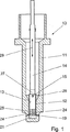
内燃機関の燃料噴射弁式のスライディング弁10は弁ハウジング11を保有し、そのハウジング11内でスライディングスリーブ12が、運動方向29で軸方向に移動可能となるようにコントロールシリンダ13内で案内される。スライディングスリーブ12は、スライディングスリーブ12内の横方向ボア16に挿入されるクロスピン15によって弁棒14に接続される。弁棒14は、アクチュエータ装置(詳細に図示せず)、例えば、電磁石によって作動される。スライディングスリーブ12及びその上部27は、ここでは磁性材料から製造でき、マグネットアーマチュアとして構成できる。
A fuel injection valve
スライディングスリーブ12は、その自由端から始まる、縦方向溝24を有し、それらの溝24は周囲全体に分配され、それらの間にばねタング25を形成し、それらのばねタング25の端部における、その外周部にコントロール面23が配置され、これらのコントロール面23はコントロールシリンダ13内のコントロール開口部17、18と協働する。コントロール開口部17、18は、外側に向いたノズルボア19、20が隣接している。これらはスライディングスリーブ12の移動方向29に互いにオフセットして配置されている。スライディング弁10の閉状態において、コントロール面23は、コントロール開口部17、18を覆う。コントロール面23は、ここでは1つまたはそれ以上のコントロール開口部17、18と作用し合うことができる。一方向へのスライディングスリーブ12の運動を通じて、対応するコントロール開口部17又は18が最初開かれ、さらにスライディングスリーブ12がさらに調整されると、前に閉じていたコントロール開口部17又は18が開かれる。スライディングスリーブ12は、したがって事実上複数のコントロール開口部17又は18を交互に、又は連続的に開くことができる。
The
コントロール面23の領域26において、ばねタング25は補強されているので、寸法安定性の増加の結果、コントロール面23はコントロール開口部17、18と密着し、漏れが生じないようにこれらの開口部17、18を密閉する。コントロール面23がコントロール開口部17、18と当接する圧力は、ばねタング25の一定のプレロードによって、又は制御される媒体の圧力を介して達成できる。この媒体は、スライディングスリーブ12のキャビティ22の中央を通過して送られ、次にノズルボア19、20を経由して運ばれる。コントロールシリンダ13は、止まり穴21を有する端面で終了する。ばねタング25が所定量だけ外向きに予め曲げられていると好都合である。さらに、ばね特性は、材料の選択及び幾何学的成形で決まる。スライディングスリーブを容易に装着できるようにするために、弁ハウジング11は、コントロールシリンダ13の方向に、円錐状領域28を保有し、その円錐状領域28によってばねタング25はコントロールシリンダ13の寸法まで強制的に戻される。
Since the
実質的に図1の細部を、拡大図で表す、図2による実施形態は、運動方向29及び/又は周囲方向に互いにオフセットされて配置されている2列のノズルボア19、20を示す。ノズルボア19、20は、運動方向29に対し異なる傾きを有し、さらに導入部で説明したタイプの燃料噴射弁に関し、それ自体知られているように、異なる断面輪郭を有することができる。
The embodiment according to FIG. 2, which represents the details of FIG. 1 in an enlarged view, shows two rows of nozzle bores 19, 20 arranged offset from one another in the direction of
Claims (11)
前記コントロール面(23)の領域において、少なくとも1つの縦方向溝(24)とばねタング(25)が形成され、前記スライディングスリーブ(12)が閉状態の場合、コントロール開口部(17、18)は前記スライディングスリーブ(12)により覆われることを特徴とするスライディング弁。A sliding sleeve (12) that is movable in the axial direction in the control cylinder and that controls at least one control opening in the control cylinder by at least one control surface of the outer periphery of the control cylinder, the control surface ( 23) is a sliding valve having a property of elastically flexing in the radial direction in the direction of the control cylinder (13) and abutting the control cylinder (13),
In the region of the control surface (23), at least one longitudinal groove (24) and a spring tongue (25) are formed, and when the sliding sleeve (12) is closed, the control openings (17, 18) A sliding valve, which is covered by the sliding sleeve (12) .
Applications Claiming Priority (2)
| Application Number | Priority Date | Filing Date | Title |
|---|---|---|---|
| DE10261175A DE10261175A1 (en) | 2002-12-20 | 2002-12-20 | spool valve |
| PCT/EP2003/012936 WO2004059161A1 (en) | 2002-12-20 | 2003-11-19 | Sliding valve |
Publications (2)
| Publication Number | Publication Date |
|---|---|
| JP2006510846A JP2006510846A (en) | 2006-03-30 |
| JP4232041B2 true JP4232041B2 (en) | 2009-03-04 |
Family
ID=32478016
Family Applications (1)
| Application Number | Title | Priority Date | Filing Date |
|---|---|---|---|
| JP2004562553A Expired - Fee Related JP4232041B2 (en) | 2002-12-20 | 2003-11-19 | Sliding valve |
Country Status (5)
| Country | Link |
|---|---|
| US (1) | US20060124763A1 (en) |
| EP (1) | EP1576281B1 (en) |
| JP (1) | JP4232041B2 (en) |
| DE (2) | DE10261175A1 (en) |
| WO (1) | WO2004059161A1 (en) |
Families Citing this family (5)
| Publication number | Priority date | Publication date | Assignee | Title |
|---|---|---|---|---|
| CN105465412A (en) * | 2015-02-17 | 2016-04-06 | 江苏瑞朗博机械设备有限公司 | Pressure bar destabilizing trigger type reversing valve |
| CN105387245B (en) * | 2015-12-16 | 2017-09-29 | 日照海卓液压有限公司 | Six five logical logic selector valves |
| US10337448B2 (en) * | 2015-12-22 | 2019-07-02 | Ford Global Technologies, Llc | Methods and systems for a fuel injector assembly |
| US10570865B2 (en) * | 2016-11-08 | 2020-02-25 | Ford Global Technologies, Llc | Fuel injector with variable flow direction |
| CN114483383B (en) * | 2022-01-28 | 2023-07-21 | 刘义亭 | Gaseous fuel injector |
Family Cites Families (18)
| Publication number | Priority date | Publication date | Assignee | Title |
|---|---|---|---|---|
| DE834310C (en) * | 1949-10-11 | 1952-03-17 | Ind A G | Shut-off device for liquids and gases |
| US3762443A (en) * | 1967-09-19 | 1973-10-02 | Tektro Inc | Resilient fluid control valve |
| US3711068A (en) * | 1970-09-25 | 1973-01-16 | J Perry | Carburetor fuel metering valve |
| DE7234188U (en) * | 1972-09-16 | 1973-01-18 | Feuchter P | DOSING DEVICE |
| US4233885A (en) * | 1978-10-24 | 1980-11-18 | Deschner Richard E | Apparatus for improved motion control |
| DE2855497A1 (en) * | 1978-12-22 | 1980-07-03 | Wabco Fahrzeugbremsen Gmbh | Seal for two or three way slide valve - formed by parts which can move relative to one another and lips with part spherical outer contour |
| DK393281A (en) * | 1981-09-07 | 1983-03-08 | H R Joergensen | SAVING VALVE FOR PIPE SYSTEMS, NECESSARY FOR DRAINAGE SYSTEM DRAINAGE SYSTEMS |
| US5392745A (en) * | 1987-02-20 | 1995-02-28 | Servojet Electric Systems, Ltd. | Expanding cloud fuel injecting system |
| DE4119402C2 (en) * | 1991-06-10 | 1995-01-12 | Mannesmann Ag | Slide valve |
| FR2699638B1 (en) * | 1992-12-21 | 1995-02-10 | Rollin Sa | Multi-way fluid distributor valve drawer, valve equipped with this drawer and method of manufacturing this drawer. |
| US5544816A (en) * | 1994-08-18 | 1996-08-13 | Siemens Automotive L.P. | Housing for coil of solenoid-operated fuel injector |
| JPH08144896A (en) * | 1994-11-25 | 1996-06-04 | Zexel Corp | Variable nozzle hole type fuel injection nozzle |
| US5626325A (en) * | 1995-09-14 | 1997-05-06 | Cummins Engine Company, Inc. | High pressure control valve for a fuel injection system |
| DE29713628U1 (en) * | 1997-07-31 | 1998-11-26 | Bosch Gmbh Robert | Fuel injector |
| DE19908420A1 (en) * | 1999-02-26 | 2000-05-25 | Siemens Ag | Blocking valve for controlling servo pressure for diesel engine fuel injection system |
| DE19916485C2 (en) * | 1999-04-13 | 2001-10-31 | Daimler Chrysler Ag | Method for operating a reciprocating piston internal combustion engine |
| DE10010863A1 (en) * | 2000-03-06 | 2001-09-27 | Bosch Gmbh Robert | Fuel injection nozzle; has nozzle body with two groups of nozzle holes opened and closed by two nozzle needles, which are independently operated and are arranged next to each other |
| DE10034445A1 (en) * | 2000-07-15 | 2002-01-24 | Bosch Gmbh Robert | Fuel injector |
-
2002
- 2002-12-20 DE DE10261175A patent/DE10261175A1/en not_active Withdrawn
-
2003
- 2003-11-19 DE DE50303752T patent/DE50303752D1/en not_active Expired - Lifetime
- 2003-11-19 WO PCT/EP2003/012936 patent/WO2004059161A1/en active IP Right Grant
- 2003-11-19 EP EP03776910A patent/EP1576281B1/en not_active Expired - Fee Related
- 2003-11-19 JP JP2004562553A patent/JP4232041B2/en not_active Expired - Fee Related
- 2003-11-19 US US10/540,290 patent/US20060124763A1/en not_active Abandoned
Also Published As
| Publication number | Publication date |
|---|---|
| DE50303752D1 (en) | 2006-07-20 |
| EP1576281B1 (en) | 2006-06-07 |
| EP1576281A1 (en) | 2005-09-21 |
| DE10261175A1 (en) | 2004-07-08 |
| JP2006510846A (en) | 2006-03-30 |
| WO2004059161A1 (en) | 2004-07-15 |
| US20060124763A1 (en) | 2006-06-15 |
Similar Documents
| Publication | Publication Date | Title |
|---|---|---|
| KR100772851B1 (en) | Fuel injection valve for internal combustion engines | |
| EP1602821B1 (en) | Fuel injection valve | |
| KR101730637B1 (en) | Valve assembly for a fluid injection valve and fluid injection valve | |
| US6772965B2 (en) | Fuel injection valve | |
| JP2000027735A (en) | Fuel injection device | |
| JPH11351104A (en) | Fuel injector with at least one movable needle guide | |
| KR20020029435A (en) | Fuel injection valve | |
| KR20040093064A (en) | Fuel injection valve for internal combustion engines | |
| US20100001101A1 (en) | Nozzle module for an injection valve | |
| KR20010075487A (en) | Fuel injection valve | |
| JP4232041B2 (en) | Sliding valve | |
| EP2857670B1 (en) | Fuel injector | |
| JP2002541375A (en) | Fuel injection valve | |
| KR102200623B1 (en) | Fluid injectors and needles for fluid injectors | |
| KR20030007739A (en) | Fuel injection valve | |
| KR20090121284A (en) | Switchable cup tappet | |
| KR20020029409A (en) | Fuel injection valve | |
| JP2005090233A (en) | Fuel injection valve | |
| JP2005504226A (en) | Valves, especially fuel injection valves | |
| US7007870B2 (en) | Fuel injection valve | |
| EP1522721B1 (en) | Injection nozzle | |
| KR20070102377A (en) | Fuel injector for an internal-combustion engine | |
| US6758416B2 (en) | Fuel injector having an expansion tank accumulator | |
| JP6669894B2 (en) | Valve cartridge for solenoid valve and associated solenoid valve | |
| CN114761681B (en) | Fuel injection valve with slide valve for internal combustion engine |
Legal Events
| Date | Code | Title | Description |
|---|---|---|---|
| RD02 | Notification of acceptance of power of attorney |
Free format text: JAPANESE INTERMEDIATE CODE: A7422 Effective date: 20070710 |
|
| RD04 | Notification of resignation of power of attorney |
Free format text: JAPANESE INTERMEDIATE CODE: A7424 Effective date: 20070720 |
|
| RD04 | Notification of resignation of power of attorney |
Free format text: JAPANESE INTERMEDIATE CODE: A7424 Effective date: 20070710 |
|
| A131 | Notification of reasons for refusal |
Free format text: JAPANESE INTERMEDIATE CODE: A131 Effective date: 20080305 |
|
| A601 | Written request for extension of time |
Free format text: JAPANESE INTERMEDIATE CODE: A601 Effective date: 20080604 |
|
| A602 | Written permission of extension of time |
Free format text: JAPANESE INTERMEDIATE CODE: A602 Effective date: 20080611 |
|
| A601 | Written request for extension of time |
Free format text: JAPANESE INTERMEDIATE CODE: A601 Effective date: 20080630 |
|
| A602 | Written permission of extension of time |
Free format text: JAPANESE INTERMEDIATE CODE: A602 Effective date: 20080709 |
|
| A601 | Written request for extension of time |
Free format text: JAPANESE INTERMEDIATE CODE: A601 Effective date: 20080728 |
|
| A602 | Written permission of extension of time |
Free format text: JAPANESE INTERMEDIATE CODE: A602 Effective date: 20080804 |
|
| A521 | Written amendment |
Free format text: JAPANESE INTERMEDIATE CODE: A523 Effective date: 20080904 |
|
| TRDD | Decision of grant or rejection written | ||
| A01 | Written decision to grant a patent or to grant a registration (utility model) |
Free format text: JAPANESE INTERMEDIATE CODE: A01 Effective date: 20081112 |
|
| A01 | Written decision to grant a patent or to grant a registration (utility model) |
Free format text: JAPANESE INTERMEDIATE CODE: A01 |
|
| A61 | First payment of annual fees (during grant procedure) |
Free format text: JAPANESE INTERMEDIATE CODE: A61 Effective date: 20081125 |
|
| FPAY | Renewal fee payment (event date is renewal date of database) |
Free format text: PAYMENT UNTIL: 20111219 Year of fee payment: 3 |
|
| R150 | Certificate of patent or registration of utility model |
Free format text: JAPANESE INTERMEDIATE CODE: R150 |
|
| FPAY | Renewal fee payment (event date is renewal date of database) |
Free format text: PAYMENT UNTIL: 20111219 Year of fee payment: 3 |
|
| FPAY | Renewal fee payment (event date is renewal date of database) |
Free format text: PAYMENT UNTIL: 20121219 Year of fee payment: 4 |
|
| FPAY | Renewal fee payment (event date is renewal date of database) |
Free format text: PAYMENT UNTIL: 20121219 Year of fee payment: 4 |
|
| FPAY | Renewal fee payment (event date is renewal date of database) |
Free format text: PAYMENT UNTIL: 20131219 Year of fee payment: 5 |
|
| LAPS | Cancellation because of no payment of annual fees |