JP4231273B2 - Eye characteristics measuring device - Google Patents
Eye characteristics measuring device Download PDFInfo
- Publication number
- JP4231273B2 JP4231273B2 JP2002327200A JP2002327200A JP4231273B2 JP 4231273 B2 JP4231273 B2 JP 4231273B2 JP 2002327200 A JP2002327200 A JP 2002327200A JP 2002327200 A JP2002327200 A JP 2002327200A JP 4231273 B2 JP4231273 B2 JP 4231273B2
- Authority
- JP
- Japan
- Prior art keywords
- unit
- light
- optical
- eye
- compensation
- Prior art date
- Legal status (The legal status is an assumption and is not a legal conclusion. Google has not performed a legal analysis and makes no representation as to the accuracy of the status listed.)
- Expired - Fee Related
Links
Images


Description
【0001】
【発明の属する技術分野】
本発明は、眼特性測定装置に係り、特に、被検眼の光学特性を波面センサを用いて精密に測定する眼特性測定装置に関する。
【0002】
【従来の技術】
近年、医学用に用いられる光学機器は、特に、眼科では、眼の屈折、調節等の眼機能、眼球内部の検査を行う光学特性測定装置として普及している。例えば、被検眼の屈折力と角膜形状とを求めるフォトレフラクトメータという装置が存在する。
【0003】
また、変形可能な鏡のような補正用光学部材を変形することにより、波動収差を補正し、幅は半分であるが波動収差と同一の形状とする網膜画像解像改善装置が開示されている(例えば、特許文献1参照)。この装置では、眼の網膜から反射されたレーザ光は、変形可能な鏡を介してハルトマンシャック波面センサに波面が形成される。形成された波面は、デジタルプロセッサによりカメラを介してデジタル化され、波動収差が測定される。デジタルデータプロセッサは、測定された波動収差を基に変形可能な鏡へフィードバックする矯正信号を発信する。変形可能な鏡は、眼の波動収差を補正するために変形し、波動収差の幅は半分であるが同一の形状を得ている。
【特許文献1】
特表2001−507258号公報
【0004】
【発明が解決しようとする課題】
しかし、収差を有する被検眼の光学特性を測定する装置において、収差量が多い場合に正確な測定が困難な場合があった。
【0005】
本発明は、以上の点に鑑み、被検眼の光学特性を測定する場合に、測定光の収差を打ち消すような補正をし、さらに補正されていない小さな収差量を測定し、精密な測定を行う眼特性測定装置を提供することを目的とする。また、本発明は、収差を打ち消すための入力値と、実際に補正されている収差にずれがある場合を考慮し、より正確な測定を行うことを目的とする。本発明は、低感度と高感度の光学系を用いて、精密かつ高速な測定を行うことを目的とする。さらに、本発明は、測定光の収差を打ち消すことにより、収差量が多い場合においても測定が可能な測定レンジの広い眼特性測定装置を提供することを目的とする。
【0006】
【課題を解決するための手段】
本発明の第1の解決手段によると、
第1波長の光束を発する第1光源部と、
上記第1光源部からの光束で被検眼網膜上の微小な領域を照明するための第1照明光学系と、
被検眼網膜から反射して戻ってくる反射光束の光学特性に基づき与えられる補償量に従って、透過又は反射する光束の収差を補償する補償光学部と、
被検眼網膜から反射して戻ってくる反射光束の一部を、上記補償光学部及び少なくとも実質的に17本のビームに変換する第1変換部材を介して受光するための第1受光光学系と、
上記第1受光光学系の受光光束を受光する第1受光部と、
第2波長の光束で上記補償光学部を照明するための第2光源部と、
上記第2光源部からの光束を、上記補償光学部及び少なくとも実質的に17本のビームに変換する第2変換部材を介して受光するための第2受光光学系と、
上記第2受光光学系の受光光束を受光する第2受光部と、
上記第1受光部の出力に基づき被検眼の光学特性を求め、該光学特性に従い補償量を求めて上記補償光学部に出力する補償量演算部と、
上記第2受光部の出力に基づく上記補償光学部で補償された光学特性、及び、上記補償光学部による補償後の上記第1受光部の出力に基づく光学特性を測定し、測定されたこれら光学特性に基づき被検眼の光学特性を求める測定演算部と
を備えた眼特性測定装置が提供される。
【0007】
本発明の第2の解決手段によると、
第1波長の光束を発する第1光源部と、
上記第1光源部からの光束で被検眼網膜上の微小な領域を照明するための第1照明光学系と、
被検眼網膜から反射して戻ってくる反射光束の光学特性に基づき与えられる補償量に従って、透過又は反射する光束の収差を補償する補償光学部と、
第2波長の光束で上記補償光学部を照明するための第2光源部と、
被検眼網膜から反射して戻ってくる反射光束の一部及び上記第2光源部からの光束を、上記補償光学部及び少なくとも実質的に17本のビームに変換する第1変換部材を介して受光するための第1受光光学系と、
上記第1受光光学系の受光光束を受光する第1受光部と、
上記第1受光部の出力に基づき被検眼の光学特性を求め、該光学特性に従い補償量を求めて上記補償光学部に出力する補償量演算部と、
上記第2光源部からの光束による上記第1受光部の出力に基づき、上記補償光学部で補償された光学特性を測定し、一方、上記第1光源部からの光束による上記第1受光部の出力に基づき、上記補償光学部で補償後の光学特性を測定し、測定されたこれら光学特性に基づき被検眼の光学特性を求める測定演算部と
を備える眼特性測定装置が提供される。
【0008】
本発明の第3の解決手段によると、
第1波長の光束を発する第1光源部と、
上記第1光源部からの光束で被検眼網膜上の微小な領域を照明するための第1照明光学系と、
被検眼網膜から反射して戻ってくる反射光束の光学特性に基づき与えられる補償量に従って、透過又は反射する光束の収差を補償する補償光学部と、
被検眼網膜から反射して戻ってくる反射光束の一部を、上記補償光学部及び少なくとも実質的に17本のビームに変換する長焦点又は高感度の第1変換部材を介して受光するための第1受光光学系と、
上記第1受光光学系の受光光束を受光する第1受光部と、
第2波長の光束で上記補償光学部を照明するための第2光源部と、
上記第2光源部からの光束を、上記補償光学部及び少なくとも実質的に17本のビームに変換する第2変換部材を介して受光するための第2受光光学系と、
上記第2受光光学系の受光光束を受光する第2受光部と、
被検眼網膜から反射して戻ってくる反射光束の一部を、上記補償光学部及び少なくとも実質的に17本のビームに変換する短焦点又は低感度のレンズ部を有する第3変換部材を介して受光するための第3受光光学系と、
上記第3受光光学系の受光光束を受光する第3受光部と、
上記第3受光部の出力に基づき被検眼の光学特性を求め、該光学特性に従い補償量を求めて上記補償光学部に出力する補償量演算部と、
上記第2受光部の出力に基づく上記補償光学部で補償された光学特性、及び、上記補償光学部による補償後の上記第1受光部の出力に基づく光学特性を測定し、測定されたこれら光学特性に基づき被検眼の光学特性を求める測定演算部と
を備えた眼特性測定装置が提供される。
【0009】
本発明の第4の解決手段によると、
第1波長の光束を発する第1光源部と、
上記第1光源部からの光束で被検眼網膜上の微小な領域を照明するための第1照明光学系と、
被検眼網膜から反射して戻ってくる反射光束の光学特性に基づき与えられる補償量に従って、透過又は反射する光束の収差を補償する補償光学部と、
第2波長の光束で上記補償光学部を照明するための第2光源部と、
被検眼網膜から反射して戻ってくる反射光束の一部及び上記第2光源部からの光束を、上記補償光学部及び少なくとも実質的に17本のビームに変換する長焦点又は高感度の第1変換部材を介して受光するための第1受光光学系と、
上記第1受光光学系の受光光束を受光する第1受光部と、
被検眼網膜から反射して戻ってくる反射光束の一部を、上記補償光学部及び少なくとも実質的に17本のビームに変換する短焦点又は低感度のレンズ部を有する第3変換部材を介して受光するための第3受光光学系と、
上記第3受光光学系の受光光束を受光する第3受光部と、
上記第3受光部の出力に基づき被検眼の光学特性を求め、該光学特性に従い補償量を求めて上記補償光学部に出力する補償量演算部と、
上記第2光源部からの光束による上記第1受光部の出力に基づき、上記補償光学部で補償された光学特性を測定し、一方、上記第1光源部からの光束による上記第1受光部の出力に基づき、上記補償光学部で補償後の光学特性を測定し、測定されたこれら光学特性に基づき被検眼の光学特性を求める測定演算部と
を備える眼特性測定装置が提供される。
【0010】
【発明の実施の形態】
1.光学系構成
(第1の実施の形態における光学系)
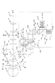
図1に、眼特性測定装置の光学系の第1の構成図を示す。
眼特性測定装置は、第1照明光学系10と、第1光源部11と、第2光源部16と、第1測定部25Aと、第2測定部25Bと、前眼部照明部30と、前眼部観察部40と、第1調整光学部50と、補償光学部60と、第2調整光学部70と、視標光学部90を備える。また、第1測定部25Aは、第1受光光学系20Aと、第1受光部21Aを有する。第2測定部25Bは、第2受光光学系20Bと、第2受光部21Bを有する。なお、被検眼100については、網膜(眼底)、角膜(前眼部)が示されている。
【0011】
以下、各部について詳細に説明する。
第1照明光学系10は、第1光源部11からの光束で被検眼100の眼底上で微小な領域を照明するためのものである。第1照明光学系10は、例えば、集光レンズと、正負一組のシリンダーレンズ13a(いわゆるバリアブルクロスシリンダー)と、リレーレンズとを備える。なお、このバリアブルクロスシリンダー13aはなくてもよい。
【0012】
第1光源部11は、第1波長の光束を発する。第1光源部11は、空間コヒーレンスが高く、時間コヒーレンスは高くないものが望ましい。ここでは、一例として、第1光源部11には、SLD(スーパールミネセンスダイオード)が採用されており、輝度が高い点光源を得ることができる。なお、第1光源部11は、SLDに限られるものではなく、レーザの様に空間、時間ともコヒーレンスが高いものでも、回転拡散板などを挿入することにより、適度に時間コヒーレンスを下げることで利用できる。そして、LEDの様に、空間、時間ともコヒーレンスが高くないものでも、光量さえ充分であれば、ピンホール等を光路の光源の位置に挿入することで、使用可能になる。また、照明用の第1光源部11の波長は、例えば、赤外域の波長(例、780nm)を使用することができる。
【0013】
第1受光光学系20Aは、例えば、被検眼100の網膜から反射して戻ってきた光束を受光し第1受光部21Aに導くためのものである。第1受光光学系20Aは、例えば、第1変換部材22A(例、ハルトマン板)と、アフォーカルレンズと、バリアブルクロスシリンダー13bと、リレーレンズを備える。第1変換部材22Aは、反射光束を少なくとも17本の複数のビームに変換するためのレンズ部を有する波面変換部材である。なお、第1変換部材22Aは、長焦点又は高感度のレンズ部を有する波面変換部材であっても良い。第1変換部材22Aには、光軸と直交する面内に配置された複数のマイクロフレネルレンズを用いることができる。眼底からの反射光は、第1変換部材22Aを介して第1受光部21A上に集光する。第1受光部21Aは、第1変換部材22Aを通過した第1受光光学系20Aからの光を受光し、第1信号を生成するためのものである。また、アフォーカルレンズ42の前側焦点は、被検眼100の瞳孔と略一致している。
【0014】
第2光源部16は、第2波長の光束を発する。第2光源部16から発せられる光束は、補償光学部60で実際に補償されている収差(補償収差)を測定するために用いられる。第2光源部16からの光束は、レンズを介してビームスプリッタ17で反射し、補償光学部60を照射する。補償光学部60で反射することによって収差を有した光束は、ビームスプリッタ18で反射し、第2受光光学系20Bで受光され、その収差が測定される。ビームスプリッタ17及び18は、例えば第1光源部11から発せられる第1波長の光束を通過し、第2光源部16から発せられる第2波長の光束を反射するダイクロイックミラーを用いることができる。この場合、第2光源部16から発せられる第2波長は、第1光源部11から発せられる第1波長と異なる波長を用いる。また、第2光源部16から発せられる光束は、被検眼100からの反射光束の偏光方向と逆の偏光光を使用してもよい。これは、ビームスプリッタ17を、被検眼100の網膜からの反射光束の偏光方向を透過し、逆の偏光方向を反射するような偏光ビームスプリッタを用いることで実現できる。また、ビームスプリッタ18は、例えば、偏光ビームスプリッタを用いることで被検眼100からの反射光束と第2光源部16からの光束を分割できる。なお、ビームスプリッタ17は、ハーフミラーを用いることもできる。
【0015】
第2受光光学系20Bは、第2光源部16から発し、補償光学部60で反射された光束を受光して第2受光部21Bに導くためのものである。第2受光光学系20Bは、例えば、第2変換部材22B(例えば、ハルトマン板)と、第1受光光学系20Aと共用されるアフォーカルレンズ及びバリアブルクロスシリンダー13b及びリレーレンズを備える。第2変換部材22Bは、補償光学部60で反射した光束を少なくとも17本の複数のビームに変換するためのレンズ部を有する波面変換部材である。第2変換部材22Bには、光軸と直交する面内に配置された複数のマイクロフレネルレンズを用いることができる。第2光源部16からの光束は、補償光学部60及び第2変換部材22Bを介して第2受光部21B上に集光する。第2受光部21Bは、第2変換部材22Bを通過した第2受光光学系20Bからの光を受光し、第2信号を生成するためのものである。第1受光光学系20Aと第2受光光学系20Bの光束は、例えば、ビームスプリッタ18により分けられる。本実施の形態では、被検眼100の網膜からの反射光束を透過し、第1受光部21Aに導き、第2光源部16からの光束を反射し、第2受光部21Bに導くようになっているが、反射と透過の関係を逆にし、受光部を入れ替えて測定を行ってもよい。
【0016】
移動部15は、第1照明光学系10と第1受光光学系20Aと第2受光光学系20Bを含む図1の点線で囲まれた部分を一体に移動させる。例えば、第1光源部11からの光束が集光する点で反射されたとして、その反射光による第1受光部21Aでの信号ピークが最大となる関係を維持して、第1受光部21Aでの信号ピークが強くなる方向に移動し、強度が最大となる位置で停止することができる。また、第1照明光学系10と第1受光光学系20Aは別々に移動させ、例えば、第1光源部11からの光束が集光する点で反射されたとして、その反射光による第1受光部21Aでの信号ピークが最大となる関係を維持して、第1受光部21Aでの信号ピークが強くなる方向に移動し、強度が最大となる位置で停止することもできる。
【0017】
第1光源部11から被検眼100への入射光は、絞り12を偏心させることで光束の入射位置を光軸に直交する方向に変更し、レンズや角膜の頂点反射を防いでノイズを押さえられる。絞り12は、径がハルトマン板22Aの有効範囲より小さく、受光側だけに眼の収差が影響する、いわゆるシングルパスの収差計測が成り立つことができる様になっている。
【0018】
なお、第1光源部11から出た入射光線は、眼底から拡散反射された測定光線と共通光路になった後は、近軸的には、眼底から拡散反射された測定光線と同じ進み方をする。但し、シングルパス測定のときは、それぞれの光線の径は違い、入射光線のビーム径は、測定光線に比べ、かなり細く設定される。具体的には、入射光線のビーム径は、例えば、被検眼100の瞳位置で1mm程度、測定光線のビーム径は、7mm程度になることもある。なお、光学系を適宜配置することで、ダブルパス測定を行うこともできる。
【0019】
前眼部照明部30は、第3波長の光束を発する第3光源部31を備え、第3光源部31からの光束で、例えば、プラチドリング又はケラトリング等を用いて前眼部を所定パターンで照射する。ケラトリングの場合、ケラト像により角膜の曲率中心付近だけのパターンを得ることができる。なお、第3光源部31から発せられる光束の第3波長は、例えば、第1波長(ここでは、780nm)と異なると共に、長い波長を選択できる(例えば、940nm)。
【0020】
前眼部観察部40は、例えば、リレーレンズ、テレセン絞りとCCDで構成される前眼部像受光部41を備え、例えば、プラチドリング、ケラトリング等の前眼部照明部30のパターンが、被検眼100の前眼部から反射して戻ってくる光束を観察する。なお、テレセン絞りは、前眼部像がぼけないようにするための絞りである。前眼部像受光部41からの信号は、例えば、角膜形状、角膜波面収差、アライメント調整等の演算に使用される。
【0021】
第1調整光学部50は、例えば、作動距離調整を主に行うものであって、光源部と、集光レンズと、受光部とを備える。ここで、作動距離調整は、例えば、光源部から射出された光軸付近の平行な光束を、被検眼100に向けて照射すると共に、この被検眼100から反射された光を、集光レンズを介して受光部で受光することにより行われる。また、被検眼100が適正な作動距離にある場合、受光部の光軸上に、光源部からのスポット像が形成される。一方、被検眼100が適正な作動距離から前後に外れた場合、光源部からのスポット像は、受光部の光軸より上又は下に形成される。なお、受光部は、光源部、光軸、受光部を含む面内での光束位置の変化を検出できればいいので、例えば、この面内に配された1次元CCD、ポジションセンシングデバイス(PSD)等を適用できる。
【0022】
補償光学部60は、変形することで測定光の収差を補償する適応光学系(アダプティブオプティクス)であり、第1受光光学系20A及び第2受光光学系20B中に配置される。補償光学部60としては、例えば、可変鏡や液晶空間光変調器を用いることができる。なお、その他、測定光の収差を補償可能な適宜の光学系を用いてもよい。可変鏡は、鏡の内部に備えられたアクチュエータによって鏡を変形させることで、光束の反射方向を変化する。また、静電容量によって変形させる方法や、ピエゾを用いて変形させる方法等もあるが、これ以外にも適宜の方法を用いることができる。液晶空間光変調器は、液晶の配光性を利用して位相を変調させるもので、鏡と同様に反射させて使用する。光路の途中で偏光子が必要であるが、本実施の形態では、ビームスプリッタ63がその役割を果たす。ビームスプリッタ63は、第1光源部11からの光束を反射し、被検眼100の網膜で反射して戻ってくる光束を透過するミラー(例えば、偏光ビームスプリッタ)で構成されている。補償光学系60は、反射させて使用するもの以外に、透過型の光学系を用いてもよい。なお、これら補償光学部60には、それに限られるわけではないが、平行光束を入射させるようにしたほうがよい。例えば、被検眼100が無収差の場合、補償光学部60には被検眼100の網膜からの反射光束が平行光として入射する。また、例えば、第2光源部16からの光束は常に平行光として入射するようになっている。
【0023】
ビームスプリッタ61は、例えば、第1波長の光束を反射し、第3波長の光束を透過するダイクロイックミラーで構成されている。また、眼底からの反射むら等による光を均一化するためのロータリープリズム62が配置されている。
【0024】
第2調整光学部70は、例えば、XY方向のアライメント調整を行うものであって、角膜頂点に輝点を作るために、アライメント用光源部と、レンズと、ビームスプリッタとを備える。
【0025】
視標光学部90は、例えば、被検眼100の風景チャート、固視や雲霧をさせる為の視標を投影する光路を含むものであって、光源部(例えば、ランプ)、固視標92、リレーレンズを備える。光源部からの光束で固視標92を眼底に照射することができ、被検眼100にその像を観察させる。
【0026】
(共役関係)
被検眼100の眼底、視標光学部90の固視標92、第1光源部11、第2光源部16、第1受光部21Aが共役である。また、被検眼100の眼の瞳(虹彩)、ロータリープリズム62、第1変換部材(ハルトマン板)22A、第1照明光学系10の測定光入射側の絞り12、可変鏡等の補償光学部60が共役である。
【0027】
上述の実施の形態は、主に、入射光線が細いシングルパスとして説明したが、本発明は、入射光線が太いダブルパスとしての眼特定測定装置に適用することも可能である。その際、光学系がダブルパス用構成で配置されるが、演算部による測定・計算処理は同様である。
【0028】
(第2の実施の形態における光学系)
図2は、眼特性測定装置の光学系の第2の構成図である。図2には、図1の点線枠にあたる部分のみを示しているが、その他の部分については図1と同様である。図2における眼特性測定装置は、さらに、短焦点又は低感度の第3測定部25C、ハーフミラー24を備える。また、図2の光学系において、第1変換部材22Aは、長焦点又は高感度のレンズ部を有する波面変換部材である。
【0029】
第3測定部25Cは、第3受光光学系20Cと、第3受光部21Cを有する。第3受光光学系20Cは、第1受光光学系20Aと同様に、被検眼100の網膜から反射して戻ってきた光束を受光し第3受光部21Cに導くためのものである。第3受光光学系20Cは、例えば、第3変換部材22C(例えば、ハルトマン板)と、第1受光光学系20Aと共用されるアフォーカルレンズ及びバリアブルクロスシリンダー13b及びリレーレンズを備える。第3変換部材22Cは、反射光束を少なくとも17本の複数のビームに変換するための短焦点又は低感度のレンズ部を有する波面変換部材である。なお、このバリアブルクロスシリンダー13bはなくてもよい。また、第3変換部材22Cは、被検眼100の瞳(虹彩)等と共役である。第3変換部材22Cには、光軸と直交する面内に配置された複数のマイクロフレネルレンズを用いることができる。眼底からの反射光は、第3変換部材22Cを介して第3受光部21C上に集光する。第3受光部21Cは、第3変換部材22Cを通過した第3受光光学系20Cからの光を受光し、第3信号を生成するためのものである。また、第3受光部21Cは、被検眼100の眼底等と共役である。第1測定部25Aと第3測定部25Cの光束は、ハーフミラー24により分けられる。もしくは、ハーフミラー24の代わりにミラー部を用いて、このミラー部が動いて光路に挿板されることにより第1又は第3測定部25A又は25Cに切り替えることもできる。
【0030】
本実施の形態における短焦点及び低感度とは、測定可能範囲にわたる第3変換部材22Cにより変換されたビームの変化が、第3変換部材22Cの変換ピッチよりも小さく設定されているものである。その結果、第3受光部21Cで得られる各スポットと格子点との対応付けがしやすく、信号処理が容易かつ高速化が図れる。一方、長焦点又は高感度による測定では、スポット位置のずれが大きくハルトマンの格子の範囲外にもスポットが存在することもある。したがって、収差量が大きい等の理由により、あまりにスポット位置がずれてしまうと、各スポットと格子点との対応付けが難しい場合があり、信号処理に時間がかかることもある。そこで、本実施の形態の一つとして、短焦点又は低感度の第3測定部25Cの信号に基づいて補償光学部60の補償量を決定し、補償された光束を長焦点又は高感度で測定することで、高速かつ正確な測定を可能としている。
【0031】
(第3の実施の形態における光学系)
図3は、眼特性測定装置の光学系の第3の構成図である。図3には、図1の点線枠にあたる部分のみを示しているが、その他の部分については図1と同様である。図3の光学系は、補償光学部60が第1及び第2及び第3受光光学系20A及び20B及び20Cに共通して挿入されている。被検眼100の網膜から反射して戻ってきた光束は、補償光学部60を介してビームスプリッタ18を通過し、ハーフミラー24で分けられ、第1及び第3測定部25A及び25Cに導かれる。もしくは、ハーフミラー24の代わりにミラー部を用いて、このミラー部が動いて光路に挿板されることにより第1又は第3測定部25A又は25Cに切り替えることもできる。また、第2光源部16からの光束は、補償光学部60を介してビームスプリッタ18で反射し、第2測定部25Bに導かれる。補償光学部60を介した光束を第3測定部25Cに導くことにより、補償後の収差及び補償収差を第3測定部25Cでも測定可能となる。また、第3測定部25Cからの出力により測定された収差が予め定められた許容値以下になるまで、補償光学部60を変形することも可能である。また、図2、図3に示す光学系は、主に、入射光線が細いシングルパスとして説明したが、ダブルパス測定用に適宜変更することもできる。
【0032】
2.電気系構成
図4は、眼特性測定装置の電気系の構成図である。
眼特性測定装置の電気系の構成は、演算部600と、制御部610と、入力部650と、表示部700と、メモリ800と、第1駆動部910と、第3駆動部911と、第2駆動部912と、第3駆動部913と、第5駆動部914を備える。演算部600は、例えば、補償量演算部601と、各種眼特性測定を行う測定演算部602とを有する。さらに、入力部650は、表示部700に表示された適宜のボタン、アイコン、位置、領域等を指示するためポインティングデバイス、各種データを入力するためのキーボード等を備える。
【0033】
また、演算部600には、第1受光部21Aからの第1信号▲4▼と、第3受光部21Cからの第3信号(14)と、前眼部観察部40からの信号▲7▼と、第1調整光学部50からの信号(10)と、第2受光部21Bからの第2信号(17)が入力される。
【0034】
測定演算部602は、第1受光部21Aからの第1信号▲4▼、第3受光部21Cからの第3信号(14)、第2受光部21Bからの第2信号(17)を入力し、例えば、光束の傾き角に基づき被検眼100の光学特性を求める。また、補償量演算部601は、例えば、第1測定部25A又は第3測定部25Cの出力から求めた光学特性に基づき、補償光学部60での補償量を求める。また、補償量演算部601は、前眼部像受光部41に基づく角膜形状から算出される角膜収差に基づいて補償を行い、収差測定が可能となるようにしてもよい。演算部600は、これら演算結果に応じた信号又は他の信号・データを、電気駆動系の制御を行う制御部610と、表示部700と、メモリ800とにそれぞれ適宜出力する。
【0035】
制御部610は、演算部600からの制御信号に基づいて、第1光源部11及び第2光源部16の点灯、消灯を制御したり、第1駆動部910〜第5駆動部914を制御するためのものである。制御部610は、例えば、演算部600での演算結果に応じた信号に基づいて、第1光源部11に対して信号▲1▼を出力し、第2調整光学部70に対して信号▲5▼を出力し、前眼部照明部30に対して信号▲6▼を出力し、第1調整光学部50に対して信号▲8▼及び▲9▼を出力し、視標光学部90に対して信号(11)を出力し、第2光源部16に対して信号(16)を出力し、さらに、第1駆動部910〜第5駆動部914に対して信号を出力する。
【0036】
第1駆動部910は、演算部600に入力された第1又は第3受光部21A又は21Cからの信号▲4▼又は(14)に基づいて、信号▲2▼を出力して、第1照明光学系10のバリアブルクロスシリンダー13aと、第1受光光学系20A(又は第3受光光学系20C)のバリアブルクロスシリンダー13bとを、適宜のレンズ移動手段を駆動させて回動させて、被検眼100の乱視成分を補正するためのものである。なお、この補正は行わなくてもよい。
【0037】
第2駆動部911は、例えば、演算部600に入力された第1及び/又は第3受光部21A及び/又は21Cからの受光信号▲4▼及び/又は(14)に基づいて、第1照明光学系10及び第1並びに第3受光光学系20A並びに20Cを光軸方向に移動させるものであり、移動部15に対して信号▲3▼を出力すると共に、移動部15のレンズ移動手段を駆動する。これら第1並びに第3受光光学系20A並びに20Cを光軸方向に移動させることにより、低次収差の球面度数成分の補償を行うことができる。
【0038】
第3駆動部912は、例えば、視標光学部90を移動させるものであり、図示しない適宜の移動手段に対して信号(12)を出力すると共に、この移動手段を駆動する。第3駆動部913は、ロータリープリズム62を回動させるものであり、図示しない適宜のレンズ移動手段に対して信号(13)を出力すると共に、このレンズ移動手段を駆動する。第5駆動部914は、補償光学部60を駆動させるものであり、補償光学部60の変形手段に対して補償量演算部602で求めた補償量に基づいて信号(15)を出力すると共に、この変形手段を駆動する。
【0039】
3.動作
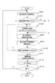
(第1の実施の形態の光学系のフローチャート)
図5及び図6は、第1の実施の形態の光学系における収差測定のフローチャートである。図5及び図6のフローチャートにおける収差測定は、図1に示す光学系を用いる形態である。演算部600は、収差測定1における第1測定部25Aからの出力に基づき、補償量を決定して補償光学部60をゆがませ、さらに、第1受光部21Aで受光された第1信号に基づく補償後の収差と、第2受光部21Bで受光された第2信号に基づく補償光学部60で補償した収差(補償収差)から被検眼100の光学特性を求める。
【0040】
まず、演算部600は、収差測定1として、第1受光部21Aからの第1信号に基づき被検眼100の収差を求める(S101)。演算部600は、第1測定部25Aの第1受光部21Aから、ハルトマン像の第1信号を入力する。次に、演算部600は、入力した第1信号から、ハルトマン像の点像移動量△x、△yを求め、点像移動量に基づいてゼルニケ係数を算出し、被検眼100の収差を求める。さらに、演算部600は、前眼部観察部40の前眼部像受光部41からの信号に基づき角膜形状、角膜収差等を求めてもよい。また、演算部600は、これら計算結果をメモリ800に記憶する。
【0041】
以下に、収差演算について説明する。演算部600は、第1測定部25Aの画像から各点像の移動量△x、△yを求める。この移動量と波面収差Wは、以下の偏微分方程式によって関係付けられる。
【0042】
【数1】

【0043】
ここで、波面収差Wをゼルニケ多項式Zi 2j−iを使った展開であらわすと、
【0044】
【数2】
上の2つの式と、測定で求められた△x、△y(よって、X、Yも含む)に関する測定値を使って、ゼルニケ係数ci 2j−iの各値を求めることができる。また、角膜収差を求める場合、前眼部観察部40の前眼部像受光部41からの信号に基づき、角膜の傾き及び角膜の高さを計算し、角膜を光学レンズと同様に扱うことにより光学特性が計算される。なお、図18、図19に、ゼルニケ多項式についての説明図(1)及び(2)を示す。
【0046】
次に、演算部600は、測定結果が得られたか判断する(S103)。演算部600は、例えば、収差測定1において取得したハルトマン像の各点像の重心位置が所定の数以上(例えば3分の1以上)取れない、又は各点像のぼけが大きいとき(例えば、無収差時の20倍以上など)、又は隣接するスポット像と分離できずに検出できない点が所定の数以上ある等の予め定められたひとつ又は複数の適宜の条件に従い判断することができる。ここで、演算部600は、測定結果が得られた場合(S103)、ステップS105の処理へ移り、一方、測定結果が得られなかった場合(S103)、図6に示すステップS151の処理へ進む。
【0047】
ステップS105では、演算部600は、求められた収差を打ち消すような補償光学部60における補償量Mを求め、制御部610及び第5駆動部914を介して、補償量Mに応じた信号(15)を出力し、可変鏡等の補償光学部60をゆがませる(S105)。また、補償光学部60は、信号(15)に従い適宜の変形手段により変形する。なお、補償光学部60は、可変鏡以外に、液晶空間光変調器を用いても良い。以下、収差を打ち消すために必要な補償光学部60における補償量Mの算出について説明する。
【0048】
図7は、可変鏡上の座標(Xm、Ym)と光学系の座標(X、Y)の関係の説明図である。補償する収差をWcとし、解析された収差の式が、
【0049】
【数3】
であるとき、可変鏡上の座標(Xm、Ym)と光学系の座標(X、Y)の関係は、可変鏡への入射角θを考慮して、
【0051】
【数4】
となる。可変鏡の補償量Mは、反射であることから2倍効くことと、目の瞳孔と可変鏡での倍率を考慮する。可変鏡の瞳孔に対する倍率をkとすると、補償量Mは、
【0053】
【数5】
となる。ここで求められた補償量Mは、収差の高次成分を含むことができる。補償光学部60は、演算部600から出力された補償量Mに基づいて変形する。なお、倍率k及び無補償状態での入射角θは予め設定された値であり、予めメモリ800に記憶されている。なお、低次成分の球面度数成分は、移動部15によって第1受光光学系20Aを移動させることにより補償することもできる。また、低次成分の乱視成分は、バリアブルクロスシリンダー13bを回動することにより補償することもできる。例えば、求められた収差のうち、3次以上の高次収差が所定以上でない場合に、演算部600は、求められた収差に従い第1受光光学系20Aを移動及び/又はバリアブルクロスシリンダー13bを回動させることができる。この場合、例えば演算部600は、求められた収差のうち球面度数成分c2 0に従い第2受光光学系20Aを移動させ、及び/又は、乱視成分c2 −2並びにc2 2に従いバリアブルクロスシリンダー13bを回動させる。さらに、演算部600は、c2 0及び/又はc2 −2並びにc2 2以外の収差に従い補償量Mを求め、補償量Mに基づいて補償光学部60を変形させる。このとき、補償量Mは、c2 0=0及び/又はc2 −2=0並びにc2 2=0として算出すればよい。なお、補償量Mは、球面度数成分及び/又は乱視成分の補償後に再度収差を測定し、この収差に基づき算出してもよい。
【0055】
ゆがませた可変鏡をさらにゆがませる場合、補償後に測定された収差に対して上記の解析と同様に補償量Mを求め、補償後の可変鏡にさらにその分を付加すればよい。また、補償光学部60により完全に収差をなくすのではなく、若干ハルトマン板への入射光を発散方向にする又は傾けるようにしてもよい。これにより第1測定部25Aにおいて、補償後の収差を高い感度で測定することができる。演算部600は、収差測定1の測定結果が得られなかった場合(S103)、図6の収差補償の処理へ移る。
【0056】
図6は、ハルトマン像から被検眼100の光学特性が求められない場合の収差測定のフローチャートである。以下、図6に示す処理について説明する。
【0057】
まず、演算部600は、おおよその収差量が分かる、もしくは適当に収差補正をしてみるか判断する(S151)。例えば、角膜収差,過去の収差データ等を参考に測定を続けるかどうか判断する。判断方法としては、演算部600は、自動的に表示したダイアログボックス、もしくはメニューから立ち上げた入力部650等から測定を続ける又は終了する信号を入力しても良い。また、演算部600は、メモリ800に角膜収差データ又は過去の収差データがあるかを検索し、データの有無によって測定を続けるか終了するかを判断しても良い。
【0058】
演算部600は、測定を続けない場合、表示部700に解析不可能通知表示を行い(S153)、測定を終了する。一方、演算部600は、測定を続ける場合、角膜収差データ、過去の収差データ等のゼルニケ係数、収差データ等を、装置内のメモリ800、もしくは入力部650から入力し、可変鏡等の補償光学部60の補償量Mを求め、制御部610及び第5駆動部914を介して可変鏡をゆがませる(S155)。また、演算部600は、前眼部観察部40の前眼部像受光部41からの信号を入力して角膜波面収差を求め、求めた収差に基づいて補償量Mを算出してもよい。補償量Mの算出についてはステップS105と同様である。演算部600は、制御部610及び第5駆動部914を介して、補償量Mに応じた信号(15)を出力し、補償光学部60をゆがませる。
【0059】
次に、演算部600は、補償後に光学特性の測定が可能か判断する(S157)。演算部600は、例えば、第1受光部21Aからハルトマン像を入力し、入力したハルトマン像の重心位置が所定の数以上(例えば3分の1)取れない、もしくは各点像のぼけが大きい(例えば、無収差時の20倍以上など)、もしくは隣接するスポット像と分離できずに検出できない点が所定の数以上ある等の予め定められたひとつ又は複数の適宜の条件に従い判断することができる。演算部600は、測定不可能な場合、さらに補償するか判断する(S159)。例えば、演算部600は、自動的に表示したダイアログボックス、もしくはメニューから立ち上げた入力部650等から測定を続ける又は終了する信号を入力しても良い。また、演算部600は、メモリ800に別の収差データがあるかを検索しても良い。演算部600は、補償する場合はステップS155へ戻り、一方、補償しない場合は、表示部700に解析不可能通知を表示し(S161)、測定を終了する。
【0060】
一方、演算部600は、測定可能な場合(S157)、図5のステップS106へ進む。
図5に戻り、演算部600は、第2受光部21Bから第2信号を取得し、補償光学部60で補償されている収差(補償収差)を測定する(S106)。第2受光部21Bで受光される光束は、第2光源部16から発した無収差の光束が補償光学部60で反射することで、補償光学部60での補償収差を有した光束である。この光束を受光し、収差を測定することで、補償光学部60での補償収差を正確に得ることができる。例えば、補償光学部60による収差を打ち消すための入力値と、実際に打ち消している収差にずれがある場合、このずれにより生ずる測定誤差を除去することができる。
【0061】
次に、演算部600は、収差測定2として、第1受光部21Aから第1信号を取得し、収差を求める(S107)。ここで求められる収差は、補償後の収差であり、第1測定部25Aによって、微小な収差を高精度に測定可能である。また、ステップS106及びS107の処理は、逆の順序で行っても良いし、並行して行うこともできる。
【0062】
演算部600は、ステップS107で得られた収差が、予め定められた許容値以下であるか判断する(S109)。例えば、演算部600は、高次収差のRMS値が0.1以下であるかを判断しても良い。収差のRMS値は、ゼルニケ係数ci 2j−iを用いて次式で算出される。
【0063】
【数6】
演算部600は、これら収差のRMS値の予め定められた一つ又は複数が許容値以下であるか判断する。
【0065】
演算部600は、収差が許容値より大きい場合(S109)、ステップS105へ戻り、さらに補償光学部60をゆがませる。一方、演算部600は、許容値より小さい場合(S109)、ステップS107で測定された収差W2に、ステップS106で測定された補償収差W1を加えて、実際の被検眼100の収差W(ゼルニケ係数ci 2j−iを含む)を求める(S111)。また、演算部600は、求められたゼルニケ係数ci 2j−iと光学系の配置(例、移動位置が初期条件でどこに来ているかなどの情報)により、既知の方法をつかって、球面度数S、乱視度数C、乱視軸A、高次球面収差等の光学特性を得ることができる。演算部600は、次式のようにゼルニケ係数の2次項から球面度数S、乱視度数C、乱視軸Aを求めることができる。
【0066】
【数7】
【0067】
次に、演算部600は、求められた収差マップ、収差係数、ハルトマン像等の測定結果を表示部700に表示し、メモリ800に記憶する(S113)。また、演算部600は、メモリ800から角膜形状データ等を読み出し、表示部700にさらに表示しても良い。
【0068】
さらに、演算部600は、測定を終了するか判断し(S115)、測定を続ける場合はステップS101に戻り、終了の場合は測定を終了する。測定終了の判断は、例えば、演算部600は、自動的に表示したダイアログボックス、もしくはメニューから立ち上げた入力部650等から測定を続ける又は終了する信号を入力しても良い。
【0069】
図8は、第1の実施の形態の光学系における収差測定のフローチャートの第1の変形例である。本変形例は、補償収差の測定と補償後の収差測定を並行して行う例である。各処理の詳細については、図5と同様であるので、同じ符号を付し説明を省略する。
【0070】
図9は、第1の実施の形態の光学系における収差測定のフローチャートの第2の変形例である。本変形例は、補償後の収差測定毎に、被検眼100の収差演算及び演算結果の出力を行う例である。
【0071】
まず、演算部600は、ステップS101〜S107及びステップS111の処理を実行する。処理の詳細については上述と同様であるので省略する。
【0072】
演算部600は、求められた波面収差マップ、収差係数、ハルトマン像等の測定結果を表示部700に表示し、メモリ800に記憶する(S201)。なお、表示部700への表示は必ずしも毎回行う必要はない。例えば、表示部700への表示処理に時間がかかる等、測定に影響を及ぼす場合、一定の測定回数毎に結果を表示するようにしても良い。
【0073】
演算部600は、ステップS111で得られた収差2が、予め定められた許容値以下であるか判断する(S109)。判断基準は、上述と同様とすることができる。演算部600は、収差が許容値より大きい場合、ステップS105へ戻り、許容値より小さい場合、求められた波面収差マップ、収差係数等の測定結果を表示部700に表示し、メモリ800に記憶する(S203)。なお、ステップS201において、既に当該測定結果の表示、記憶を行っている場合は、ステップS203の処理を省略しても良い。なお、演算部600は、収差が許容値以下であるかを判断する代わりに、さらに補償光学部60をゆがませるかの入力を指示する表示を表示部700に出力し、入力部650から信号を入力するようにしてもよい。次に、演算部600は、ステップS115の処理を実行する。処理の詳細は上述と同様である。
【0074】
(第2の実施の形態の光学系のフローチャート)
図10は、第2の実施の形態の光学系における収差測定のフローチャートである。図10は、図2又は図3に示すような長焦点又は高感度の第1測定部25Aと、短焦点または低感度の第3測定部25Cを備える光学系を用いた形態におけるフローチャートである。演算部600は、短焦点または低感度の第3測定部25Cの信号に基づき補償光学部60での補償量Mを高速に求め、補償光学部60をゆがませる。また、演算部600は、第2受光部21Bで受光された第2信号に基づく補償光学部60での補償収差と、長焦点又は高感度の第1測定部25Aの信号に基づく補償後の収差から被検眼100の光学特性を求める。
【0075】
まず、演算部600は、短焦点又は低感度の第3測定部25Cでの信号に基づいて収差測定1を行う(S251)。演算部600は、第3測定部25Cの第3受光部21Cからハルトマン像を取得し、取得した画像に基づき、スポット像の重心点を検出する。無収差での重心点を中心とする矩形エリア内でそのスポットと対応する重心位置を探すことで高速可能となるように対応付けする。演算部600は、得られたスポット像の重心点に基づいて、被検眼100の粗い収差を求める。
次に、演算部600は、ステップS103、S105、106の処理を実行する。処理の詳細は上述と同様であるので省略する。
【0076】
演算部600は、長焦点又は高感度の第1測定部25Aからの信号に基づいて収差測定2を行う(S257)。演算部600は、第1測定部25Aの第1受光部21Aから、ハルトマン像の第1信号を入力する。次に、演算部600は、入力した第1信号から、ハルトマン像の点像移動量を求め、点像移動量に基づき被検眼100の光学特性を求める。従来の長焦点又は高感度の測定部を用いる収差測定では、スポット像のずれが大きくなることがあり、スポット像の対応付けに時間がかかる、又は、対応が取れず測定ができない場合がある。本実施の形態では、入力したハルトマン像の第1信号は、被検眼100の収差がある程度打ち消されているハルトマン像であるため、長焦点又は高感度であってもスポットの位置ずれは小さくなっており、精密かつ高速な収差演算が可能である。また、ステップS106及びS257の処理は、逆の順序で行っても良いし、並行して行っても良い。
【0077】
次に、演算部600は、ステップS109〜S115の処理を実行する。処理の詳細は上述と同様であるので省略する。なお、第2の実施の形態において、図9に示す変形例のように、補償後の収差測定毎に、被検眼100の収差演算及び演算結果の出力を行う変形も可能である。
【0078】
(第3の実施の形態の光学系のフローチャート)
第3の実施の形態の光学系におけるフローチャートは、図10に示すフローチャートを用いることができる。なお、図3に示す光学系を用いた場合、ステップS106における補償収差の測定は、第2受光光学系20Bを用いる代わりに、第3受光光学系20Cを用いることも可能である。また、演算部600は、ステップS257の第1測定部25Aでの収差測定2よりも前に、第3受光部21Cの出力に基づく収差が、予め定められた許容値以下となるように補償光学部60を変形させても良い。
【0079】
図11は、第3の実施の形態の光学系における収差測定のフローチャートの変形例である。本変形例は、図3に示す光学系を用いて収差が補償された光束を第3受光部21Cで受光し、第3受光部21Cからの信号に基づき求められる収差が、予め定められた許容値以下になるように補償を行う例である。
【0080】
まず、演算部600は、ステップS251、S103、S105の各処理を実行する。処理の詳細については上述と同様であるので省略する。次に、演算部600は、第3測定部25Cでの信号に基づいて、補償後の収差の測定を行う(S253)。処理の詳細は、上述のステップS251と同様であるので省略する。演算部600は、ステップS253で求められた収差が、予め定められた第1許容値以下であるか判断する(S255)。例えば、演算部600は、高次収差のRMS値が0.1以下であるかを判断しても良い。演算部600は、収差が第1許容値より大きい場合、ステップS105へ戻り、さらに補償光学部60をゆがませる。一方、演算部600は、収差が第1許容値より小さい場合、ステップS106の処理へ移る。
【0081】
また、演算部600は、収差が第1許容値以下であるかを判断する代わりに、第1受光部21Aから第1信号を入力し、第1信号に基づく測定が可能かを判断しても良い。演算部600は、例えば、入力した第1信号に基づく各点像の重心位置が所定の数以上(例えば3分の1以上)取れない、又は各点像のぼけが大きい(例えば、無収差時の20倍以上など)、又は隣接するスポット像と分離できずに検出できない点が所定の数以上ある等の予め定められたひとつ又は複数の条件により、第1信号に基づく測定が不可能と判断することができる。また、判断条件は、適宜の条件を用いてよい。ここで、演算部600は、測定不可能と判断した場合、ステップS105の処理へ移り、一方、測定可能と判断した場合ステップS106の処理へ移る。
【0082】
演算部600は、ステップS106、S257の処理を実行する。処理の詳細については上述と同様であるので省略する。次に、演算部600は、ステップS257で求められた収差2が、予め定められた第2許容値以下であるか判断する(S259)。例えば、演算部600は、高次収差のRMS値が0.1以下であるかを判断しても良い。また、第1許容値と第2許容値は、異なる値を取ることができる。例えば、測定の感度を考慮して、第1許容値≧第2許容値としてもよい。演算部600は、収差2が第2許容値より大きい場合(S259)、収差2に従い、補償光学部60をさらにゆがませ(S261)、ステップS257へ戻る。補償光学部60をゆがませる処理の詳細は、ステップS105と同様である。一方、演算部600は、収差2が第2許容値より小さい場合、ステップS111の処理へ移る。
次に、演算部600は、ステップS111〜S115の処理を実行する。処理の詳細は上述と同様であるので省略する。
【0083】
4.変形例
(第1の実施の形態の変形例)
図12は、眼特性測定装置の光学系の第4の構成図である。図12は、図1における収差測定用の第1測定部25Aと、補償収差測定用の第2測定部25Bを共用する変形例である。例えば、第1光源部11と第2光源部16を交互に点灯することで、第1受光光学系20Aには、被検眼100から反射して戻ってくる光束と、第2光源部16から発した光束が切り替えられて入射する。また、第1光源部11と第2光源部16の前にチョッパーを設け、第1受光光学系20Aに入射する光束を制御するようにしてもよい。なお、チョッパー以外にも、光束を遮断する適宜の手段を用いてもよい。その他各部の詳細な説明については、図1と同様であるので同じ符号を付し省略する。また、図12には、図1の点線枠にあたる部分のみを示しているが、それ以外の部分については図1と同様である。
【0084】
図13は、第1の実施の形態の変形例における第1のフローチャートである。図13は、図12に示す測定部を共用した光学系を用いて、1つの測定部を切り替えることにより、補償収差の測定と、補償後の収差の測定を行うフローチャートである。
【0085】
まず、演算部600は、第1測定部25Aからの出力に基づく被検眼100の収差測定1を行う(S301)。演算部600は、例えば、第1光源部11を点灯、第2光源部16を消灯することで、被検眼100で反射した光束が第1受光光学系20Aに入射するようにし、第1受光部21Aから第1信号を入力する。次に、演算部600は、入力した第1信号に基づき被検眼100の収差を求める。収差の演算については、上述と同様である。さらに、演算部600は、前眼部観察部40の前眼部像受光部41からの信号に基づき角膜形状、角膜収差等を求めてもよい。また、演算部600は、これら計算結果をメモリ800に記憶する。
演算部600は、ステップS103、S105の処理を実行する。処理の詳細は上述と同様であるので省略する。
【0086】
演算部600は、第1測定部25Aからの信号に基づき、補償収差を測定する(S306)。演算部600は、例えば、第1光源部11を消灯、第2光源部16を点灯することで、第2光源部16から発し、補償光学部60で反射した光束が第1受光光学系20Aに入射するようにする。さらに、演算部600は、第1受光部21Aから第1信号を入力し、入力した第1信号に基づいて、補償光学部60での補償収差を測定する。収差の演算については、上述と同様である。また、演算部600は、求めた収差をメモリ800に記憶する。
【0087】
次に、演算部600は、第1測定部25Aからの出力に基づく被検眼100の収差測定2を行う(S307)。処理の詳細は、ステップS301と同様である。
【0088】
なお、上述の処理では、演算部600は、第1受光光学系20Aへ入射する光束を、第1及び第2光源部11及び16の点灯・消灯によって切り替えているが、第1及び第2光源部11及び16の前にチョッパー等の光束を遮断する手段を設け、これを制御することにより第1受光光学系20Aへ入射する光束を切り替えるようにしてもよい。また、ステップS306とS307の処理は、順序を逆にしてもよい。
演算部600は、ステップS109〜S115の処理を実行する。処理の詳細については上述と同様であるので省略する。
【0089】
図14は、第1の実施の形態の変形例における第2のフローチャートである。図14は、補償後の収差測定毎に、被検眼100の収差演算及び演算結果の出力を行う変形例である。各処理の詳細については図9及び図13と同様であるので、同じ符号を付しその説明は省略する。
【0090】
(第2の実施の形態の変形例)
図15は、眼特性測定装置の光学系の第5の構成図である。図15は、図2における収差測定用の第1測定部25Aと、補償収差測定用の第2測定部25Bを共用する変形例である。例えば、第1光源部11と第2光源部16を交互に点灯することで、第1受光部21Aは、被検眼100から反射して戻ってくる光束と、第2光源部16から発した光束を切り替えて受光する。また、第1光源部11と第2光源部16の前にチョッパー等の適宜の光束遮断手段を設け、第1受光光学系20A及び第3受光光学系20Cに入射する光束を制御するようにしてもよい。その他各部の詳細な説明については、図2と同様であるので同じ符号を付し省略する。図15には、図1の点線枠にあたる部分のみを示しているが、それ以外の部分については図1と同様である。
【0091】
図16は、第2の実施の形態の変形例におけるフローチャートである。図16は、図15に示す短焦点又は低感度の第3受光光学系20Cを備える光学系に対するフローチャートである。この例では、1つの測定部を切り替えることにより、補償収差の測定と、眼特性測定用の測定を行う。各処理の詳細については図10、図13と同様であるので、同じ符号を付しその説明は省略する。また、図11に示す変形例と同様に、第3測定部25Cからの出力により測定された収差が予め定められた許容値以下になるまで、補償光学部60を変形することも可能である。
【0092】
(第3の実施の形態の変形例)
図17は、眼特性測定装置の光学系の第6の構成図である。図17は、図3における収差測定用の第1測定部25Aと、補償収差測定用の第2測定部25Bを共用する変形例である。第1の実施の形態の変形例と同様に、第1受光光学20Aに入射する光束を切り替えて測定する。また、その他各部の詳細な説明については、図3と同様であるので同じ符号を付し省略する。図17には、図1の点線枠にあたる部分のみを示しているが、それ以外の部分については図1と同様である。
また、第3の実施の形態の変形例におけるフローチャートは、図16に示すフローチャートを用いることができる。
【0093】
【発明の効果】
本発明によると、被検眼100の光学特性を測定する場合に、測定光の収差を打ち消すような補正をし、さらに補正されていない小さな収差量を測定し、精密な測定を行う眼特性測定装置が提供できる。また、本発明によると、収差を打ち消すための入力値と、実際に補償されている収差にずれの影響を除去し、より正確な測定を行うことができる。本発明によると、低感度と高感度の光学系の特性を生かし、精密かつ高速な測定ができる。さらに、本発明によると、測定光の収差を打ち消すことにより、収差量が多い場合においても測定が可能な測定レンジの広い眼特性測定装置が提供できる。
【図面の簡単な説明】
【図1】眼特性測定装置の光学系の第1の構成図。
【図2】眼特性測定装置の光学系の第2の構成図。
【図3】眼特性測定装置の光学系の第3の構成図。
【図4】眼特性測定装置の電気系の構成図。
【図5】第1の実施の形態の光学系における収差測定のフローチャート。
【図6】ハルトマン像から被検眼の光学特性が求められない場合の収差測定のフローチャート。
【図7】可変鏡上の座標と光学系の座標の関係の説明図。
【図8】第1の実施の形態の光学系における収差測定のフローチャートの第1の変形例。
【図9】第1の実施の形態の光学系における収差測定のフローチャートの第2の変形例。
【図10】第2の実施の形態の光学系における収差測定のフローチャート。
【図11】第3の実施の形態の光学系における収差測定のフローチャートの変形例。
【図12】眼特性測定装置の光学系の第4の構成図。
【図13】第1の実施の形態の変形例における第1のフローチャート。
【図14】第1の実施の形態の変形例における第2のフローチャート。
【図15】眼特性測定装置の光学系の第5の構成図。
【図16】第2の実施の形態の変形例におけるフローチャート。
【図17】眼特性測定装置の光学系の第6の構成図。
【図18】ゼルニケ多項式(1)。
【図19】ゼルニケ多項式(2)。
【符号の説明】
10 第1照明光学系
11 第1光源部
16 第2光源部
20A 第1受光光学系
21A 第1受光部
25A 第1測定部
20C 第3受光光学系
21C 第3受光部
25C 第3測定部
20B 第2受光光学系
21B 第2受光部
25B 第2測定部
30 前眼部観察部
40 前眼部照明部
50 第1調整光学部
60 補償光学部
70 第2調整光学部
90 視標光学部
600 演算部
610 制御部
650 入力部
700 表示部
800 メモリ[0001]
BACKGROUND OF THE INVENTION
The present invention relates to an eye characteristic measuring apparatus, and more particularly to an eye characteristic measuring apparatus that accurately measures optical characteristics of an eye to be examined using a wavefront sensor.
[0002]
[Prior art]
2. Description of the Related Art In recent years, optical instruments used for medical use have become widespread as optical characteristic measuring apparatuses that perform eye functions such as eye refraction and adjustment, and examination of the inside of an eyeball, particularly in ophthalmology. For example, there is an apparatus called a photorefractometer that obtains the refractive power and corneal shape of the eye to be examined.
[0003]
Also disclosed is a retinal image resolution improving apparatus that corrects wave aberration by deforming a deformable optical member such as a deformable mirror, and has a half width but the same shape as the wave aberration. (For example, refer to Patent Document 1). In this device, the laser light reflected from the retina of the eye forms a wavefront on the Hartmann Shack wavefront sensor via a deformable mirror. The formed wavefront is digitized via a camera by a digital processor, and wave aberration is measured. The digital data processor transmits a correction signal that feeds back to the deformable mirror based on the measured wave aberration. The deformable mirror is deformed to correct the wave aberration of the eye and has the same shape although the width of the wave aberration is half.
[Patent Document 1]
JP-T-2001-507258
[0004]
[Problems to be solved by the invention]
However, in an apparatus for measuring the optical characteristics of an eye having an aberration, accurate measurement may be difficult when the amount of aberration is large.
[0005]
In view of the above points, the present invention performs correction so as to cancel the aberration of the measurement light when measuring the optical characteristics of the eye to be measured, and further measures a small amount of uncorrected aberration to perform precise measurement. An object of the present invention is to provide an eye characteristic measuring device. Another object of the present invention is to perform more accurate measurement in consideration of a case where there is a difference between an input value for canceling out aberration and an actually corrected aberration. An object of the present invention is to perform precise and high-speed measurement using an optical system with low sensitivity and high sensitivity. Furthermore, an object of the present invention is to provide an eye characteristic measuring device having a wide measurement range that can be measured even when the amount of aberration is large by canceling out the aberration of the measuring light.
[0006]
[Means for Solving the Problems]
According to the first solution of the present invention,
A first light source that emits a light beam having a first wavelength;
A first illumination optical system for illuminating a minute region on the retina of the eye to be examined with a light beam from the first light source unit;
A compensation optical unit that compensates for aberration of the transmitted or reflected light beam according to the compensation amount given based on the optical characteristic of the reflected light beam reflected and returned from the eye retina;
A first light receiving optical system for receiving a part of the reflected light beam reflected from the retina of the eye to be examined through the compensation optical unit and the first conversion member that converts the reflected light into at least substantially 17 beams; ,
A first light receiving portion for receiving a light flux of the first light receiving optical system;
A second light source unit for illuminating the adaptive optics unit with a light beam of a second wavelength;
A second light receiving optical system for receiving the light beam from the second light source unit via the compensation optical unit and a second conversion member that converts at least substantially 17 beams;
A second light receiving portion for receiving a light flux of the second light receiving optical system;
A compensation amount calculation unit for obtaining an optical characteristic of the eye to be examined based on an output of the first light receiving unit, obtaining a compensation amount according to the optical characteristic, and outputting the compensation amount to the compensation optical unit;
The optical characteristics compensated by the compensating optical unit based on the output of the second light receiving unit and the optical characteristics based on the output of the first light receiving unit after compensation by the compensating optical unit are measured, and these measured opticals A measurement calculation unit for obtaining the optical characteristics of the eye to be examined based on the characteristics;
Is provided.
[0007]
According to the second solution of the present invention,
A first light source that emits a light beam having a first wavelength;
A first illumination optical system for illuminating a minute region on the retina of the eye to be examined with a light beam from the first light source unit;
A compensation optical unit that compensates for aberration of the transmitted or reflected light beam according to the compensation amount given based on the optical characteristic of the reflected light beam reflected and returned from the eye retina;
A second light source unit for illuminating the adaptive optics unit with a light beam of a second wavelength;
A part of the reflected light beam reflected from the retina of the eye to be examined and the light beam from the second light source unit are received through the adaptive optics unit and the first conversion member that converts at least substantially 17 beams. A first light receiving optical system for
A first light receiving portion for receiving a light flux of the first light receiving optical system;
A compensation amount calculation unit for obtaining an optical characteristic of the eye to be examined based on an output of the first light receiving unit, obtaining a compensation amount according to the optical characteristic, and outputting the compensation amount to the compensation optical unit;
Based on the output of the first light receiving unit by the light beam from the second light source unit, the optical characteristic compensated by the compensation optical unit is measured, while the first light receiving unit by the light beam from the first light source unit is measured. Based on the output, a measurement calculation unit that measures the optical characteristics after compensation by the adaptive optics unit, and obtains the optical characteristics of the eye to be inspected based on the measured optical characteristics;
Is provided.
[0008]
According to the third solution of the present invention,
A first light source that emits a light beam having a first wavelength;
A first illumination optical system for illuminating a minute region on the retina of the eye to be examined with a light beam from the first light source unit;
A compensation optical unit that compensates for aberration of the transmitted or reflected light beam according to the compensation amount given based on the optical characteristic of the reflected light beam reflected and returned from the eye retina;
For receiving a part of the reflected light beam reflected from the retina of the eye to be examined through the adaptive optics and at least substantially the first conversion member having a long focus or high sensitivity for converting the beam into 17 beams. A first light receiving optical system;
A first light receiving portion for receiving a light flux of the first light receiving optical system;
A second light source unit for illuminating the adaptive optics unit with a light beam of a second wavelength;
A second light receiving optical system for receiving the light beam from the second light source unit via the compensation optical unit and a second conversion member that converts at least substantially 17 beams;
A second light receiving portion for receiving a light flux of the second light receiving optical system;
Via a third conversion member having a short-focus or low-sensitivity lens unit that converts part of the reflected light beam reflected and returned from the retina of the eye to be converted into at least substantially 17 beams. A third light receiving optical system for receiving light;
A third light receiving portion for receiving a light flux of the third light receiving optical system;
A compensation amount calculation unit for obtaining an optical characteristic of the eye to be examined based on an output of the third light receiving unit, obtaining a compensation amount according to the optical characteristic, and outputting the compensation amount to the compensation optical unit;
The optical characteristics compensated by the compensating optical unit based on the output of the second light receiving unit and the optical characteristics based on the output of the first light receiving unit after compensation by the compensating optical unit are measured, and these measured opticals A measurement calculation unit for obtaining the optical characteristics of the eye to be examined based on the characteristics;
Is provided.
[0009]
According to the fourth solution of the present invention,
A first light source that emits a light beam having a first wavelength;
A first illumination optical system for illuminating a minute region on the retina of the eye to be examined with a light beam from the first light source unit;
A compensation optical unit that compensates for aberration of the transmitted or reflected light beam according to the compensation amount given based on the optical characteristic of the reflected light beam reflected and returned from the eye retina;
A second light source unit for illuminating the adaptive optics unit with a light beam of a second wavelength;
A long-focus or high-sensitivity first that converts part of the reflected light beam reflected from the retina of the eye to be examined and the light beam from the second light source unit into the adaptive optics unit and at least substantially 17 beams. A first light receiving optical system for receiving light through the conversion member;
A first light receiving portion for receiving a light flux of the first light receiving optical system;
Via a third conversion member having a short-focus or low-sensitivity lens unit that converts part of the reflected light beam reflected and returned from the retina of the eye to be converted into at least substantially 17 beams. A third light receiving optical system for receiving light;
A third light receiving portion for receiving a light flux of the third light receiving optical system;
A compensation amount calculation unit for obtaining an optical characteristic of the eye to be examined based on an output of the third light receiving unit, obtaining a compensation amount according to the optical characteristic, and outputting the compensation amount to the compensation optical unit;
Based on the output of the first light receiving unit by the light beam from the second light source unit, the optical characteristic compensated by the compensation optical unit is measured, while the first light receiving unit by the light beam from the first light source unit is measured. Based on the output, a measurement calculation unit that measures the optical characteristics after compensation by the adaptive optics unit, and obtains the optical characteristics of the eye to be inspected based on the measured optical characteristics;
Is provided.
[0010]
DETAILED DESCRIPTION OF THE INVENTION
1. Optical system configuration
(Optical system in the first embodiment)
FIG. 1 shows a first configuration diagram of an optical system of an eye characteristic measuring apparatus.
The eye characteristic measurement device includes a first illumination
[0011]
Hereinafter, each part will be described in detail.
The first illumination
[0012]
The first
[0013]
The first light receiving
[0014]
The second
[0015]
The second light receiving
[0016]
The moving
[0017]
Incident light from the first
[0018]
Note that the incident light beam emitted from the first
[0019]
The anterior ocular
[0020]
The anterior ocular
[0021]
For example, the first adjustment optical unit 50 mainly adjusts the working distance, and includes a light source unit, a condensing lens, and a light receiving unit. Here, the working distance adjustment is performed, for example, by irradiating a parallel light beam emitted from the light source unit in the vicinity of the optical axis toward the
[0022]
The compensation
[0023]
The
[0024]
For example, the second adjustment
[0025]
The target
[0026]
(Conjugate relationship)
The fundus of the
[0027]
Although the above-described embodiment has been described mainly as a single path with a thin incident light beam, the present invention can also be applied to an eye-specific measuring device as a double path with a large incident light beam. At this time, the optical system is arranged in a double-pass configuration, but the measurement / calculation processing by the calculation unit is the same.
[0028]
(Optical system in the second embodiment)
FIG. 2 is a second configuration diagram of the optical system of the eye characteristic measuring apparatus. FIG. 2 shows only the portion corresponding to the dotted line frame in FIG. 1, but the other portions are the same as those in FIG. The eye characteristic measuring apparatus in FIG. 2 further includes a
[0029]
The
[0030]
In the present embodiment, the short focus and the low sensitivity are such that the change in the beam converted by the
[0031]
(Optical system in the third embodiment)
FIG. 3 is a third configuration diagram of the optical system of the eye characteristic measuring apparatus. FIG. 3 shows only a portion corresponding to the dotted line frame in FIG. 1, but the other portions are the same as those in FIG. In the optical system of FIG. 3, the compensation
[0032]
2. Electrical system configuration
FIG. 4 is a configuration diagram of an electrical system of the eye characteristic measuring apparatus.
The configuration of the electrical system of the eye characteristic measurement device includes a calculation unit 600, a control unit 610, an
[0033]
In addition, the calculation unit 600 includes a first signal (4) from the first
[0034]
The
[0035]
The control unit 610 controls turning on and off of the first
[0036]
The
[0037]
For example, the
[0038]
For example, the
[0039]
3. Action
(Flowchart of the optical system of the first embodiment)
5 and 6 are flowcharts of aberration measurement in the optical system according to the first embodiment. The aberration measurement in the flowcharts of FIGS. 5 and 6 is a form using the optical system shown in FIG. The calculation unit 600 determines the compensation amount based on the output from the
[0040]
First, as the
[0041]
The aberration calculation will be described below. The calculation unit 600 calculates the movement amounts Δx and Δy of each point image from the image of the
[0042]
[Expression 1]
[0043]
Here, wavefront aberration W is expressed by Zernike polynomial Zi 2j-iExpressing with deployment,
[0044]
[Expression 2]
Using the above two equations and the measured values for Δx and Δy (and thus including X and Y) obtained by measurement, the Zernike coefficient ci 2j-iEach value of can be obtained. Further, when determining corneal aberration, the cornea tilt and cornea height are calculated based on the signal from the anterior segment image
[0046]
Next, the calculation unit 600 determines whether a measurement result is obtained (S103). For example, when the center of gravity of each point image of the Hartmann image acquired in the
[0047]
In step S105, the calculation unit 600 obtains the compensation amount M in the compensation
[0048]
FIG. 7 shows coordinates (Xm, Ym) And the coordinates (X, Y) of the optical system. The aberration to be compensated is Wc, and the analyzed aberration equation is
[0049]
[Equation 3]
The coordinates on the deformable mirror (Xm, Ym) And the coordinates (X, Y) of the optical system in consideration of the incident angle θ to the deformable mirror,
[0051]
[Expression 4]
It becomes. The compensation amount M of the variable mirror takes into account the double effect due to reflection and the magnification of the pupil of the eye and the variable mirror. If the magnification of the deformable mirror with respect to the pupil is k, the compensation amount M is
[0053]
[Equation 5]
It becomes. The compensation amount M obtained here can include higher-order components of aberration. The
[0055]
When the distorted deformable mirror is further distorted, a compensation amount M is obtained for the aberration measured after compensation in the same manner as in the above analysis, and that amount is further added to the compensated deformable mirror. In addition, the aberration may not be completely eliminated by the
[0056]
FIG. 6 is a flowchart of aberration measurement when the optical characteristics of the
[0057]
First, the calculation unit 600 determines whether an approximate amount of aberration is known or whether to correct the aberration appropriately (S151). For example, it is determined whether or not to continue the measurement with reference to corneal aberration, past aberration data, and the like. As a determination method, the calculation unit 600 may input a signal for continuing or ending the measurement from an automatically displayed dialog box or an
[0058]
When the measurement unit 600 does not continue the measurement, the calculation unit 600 displays an analysis impossible notification on the display unit 700 (S153), and ends the measurement. On the other hand, when the measurement unit 600 continues measurement, Zernike coefficients such as corneal aberration data and past aberration data, aberration data, and the like are input from the
[0059]
Next, the calculation unit 600 determines whether the optical characteristics can be measured after compensation (S157). The calculation unit 600 receives, for example, a Hartmann image from the first
[0060]
On the other hand, if measurement is possible (S157), operation unit 600 proceeds to step S106 in FIG.
Returning to FIG. 5, the arithmetic unit 600 acquires the second signal from the second light receiving unit 21 </ b> B and measures the aberration (compensation aberration) compensated by the adaptive optics unit 60 (S <b> 106). The light beam received by the second light receiving unit 21 </ b> B is a light beam having the compensation aberration at the compensation
[0061]
Next, as the
[0062]
The calculation unit 600 determines whether the aberration obtained in step S107 is equal to or less than a predetermined allowable value (S109). For example, the calculation unit 600 may determine whether the RMS value of high-order aberration is 0.1 or less. The RMS value of the aberration is the Zernike coefficient ci 2j-iIs calculated by the following equation.
[0063]
[Formula 6]
The calculation unit 600 determines whether one or more of the RMS values of these aberrations are equal to or less than an allowable value.
[0065]
If the aberration is larger than the allowable value (S109), the calculation unit 600 returns to step S105 and further distorts the
[0066]
[Expression 7]
[0067]
Next, the arithmetic unit 600 displays the obtained aberration map, aberration coefficient, Hartmann image, and other measurement results on the display unit 700 and stores them in the memory 800 (S113). In addition, the calculation unit 600 may read corneal shape data and the like from the
[0068]
Further, the calculation unit 600 determines whether or not to end the measurement (S115). When the measurement is continued, the process returns to step S101, and when the measurement is ended, the measurement is ended. For example, the calculation unit 600 may input a signal for continuing or ending the measurement from an automatically displayed dialog box or an
[0069]
FIG. 8 is a first modification of the flowchart of aberration measurement in the optical system according to the first embodiment. This modification is an example in which the measurement of compensation aberration and the measurement of aberration after compensation are performed in parallel. The details of each process are the same as those in FIG.
[0070]
FIG. 9 is a second modification of the flowchart of aberration measurement in the optical system according to the first embodiment. This modification is an example in which the aberration calculation of the eye to be examined 100 and the calculation result are output every time the aberration measurement after compensation is performed.
[0071]
First, the calculation unit 600 executes the processes of steps S101 to S107 and step S111. The details of the processing are the same as described above, and will be omitted.
[0072]
The calculation unit 600 displays the measurement results such as the obtained wavefront aberration map, aberration coefficient, Hartmann image, etc. on the display unit 700 and stores them in the memory 800 (S201). Note that the display on the display unit 700 is not necessarily performed every time. For example, when the measurement is affected, for example, it takes a long time for the display process on the display unit 700, the result may be displayed every certain number of measurements.
[0073]
The calculation unit 600 determines whether the
[0074]
(Flowchart of optical system of second embodiment)
FIG. 10 is a flowchart of aberration measurement in the optical system according to the second embodiment. FIG. 10 is a flowchart in a form using an optical system including the long focus or high sensitivity
[0075]
First, the calculation unit 600 performs the
Next, the calculating part 600 performs the process of step S103, S105, 106. The details of the processing are the same as described above, and will be omitted.
[0076]
The calculation unit 600 performs the
[0077]
Next, the calculating part 600 performs the process of step S109-S115. The details of the processing are the same as described above, and will be omitted. In the second embodiment, as in the modification shown in FIG. 9, it is possible to perform a modification for calculating the aberration of the
[0078]
(Flowchart of optical system according to the third embodiment)
As the flowchart in the optical system of the third embodiment, the flowchart shown in FIG. 10 can be used. When the optical system shown in FIG. 3 is used, the compensation aberration measurement in step S106 can use the third light receiving
[0079]
FIG. 11 is a modification of the flowchart of aberration measurement in the optical system according to the third embodiment. In this modification, a light beam whose aberration has been compensated using the optical system shown in FIG. 3 is received by the third
[0080]
First, the calculation unit 600 executes each process of steps S251, S103, and S105. The details of the processing are the same as described above, and will be omitted. Next, the computing unit 600 measures the compensated aberration based on the signal from the
[0081]
Further, instead of determining whether the aberration is equal to or less than the first allowable value, the calculation unit 600 receives the first signal from the first
[0082]
The calculation unit 600 executes the processes of steps S106 and S257. The details of the processing are the same as described above, and will be omitted. Next, the calculation unit 600 determines whether or not the
Next, the calculating part 600 performs the process of step S111-S115. The details of the processing are the same as described above, and will be omitted.
[0083]
4). Modified example
(Modification of the first embodiment)
FIG. 12 is a fourth block diagram of the optical system of the eye characteristic measuring apparatus. FIG. 12 shows a modification in which the
[0084]
FIG. 13 is a first flowchart in the modification of the first embodiment. FIG. 13 is a flowchart for measuring the compensation aberration and measuring the compensated aberration by switching one measurement unit using the optical system sharing the measurement unit shown in FIG.
[0085]
First, the calculation unit 600 performs the
The calculation unit 600 executes the processes of steps S103 and S105. The details of the processing are the same as described above, and will be omitted.
[0086]
The calculation unit 600 measures the compensation aberration based on the signal from the
[0087]
Next, the calculation unit 600 performs the
[0088]
In the above-described processing, the arithmetic unit 600 switches the light beam incident on the first light receiving
The calculation unit 600 executes the processes of steps S109 to S115. The details of the processing are the same as described above, and will be omitted.
[0089]
FIG. 14 is a second flowchart in the modification of the first embodiment. FIG. 14 is a modified example in which the aberration calculation of the
[0090]
(Modification of the second embodiment)
FIG. 15 is a fifth block diagram of the optical system of the eye characteristic measuring apparatus. FIG. 15 shows a modification in which the
[0091]
FIG. 16 is a flowchart in the modification of the second embodiment. FIG. 16 is a flowchart for an optical system including the short-focus or low-sensitivity third light receiving
[0092]
(Modification of the third embodiment)
FIG. 17 is a sixth configuration diagram of the optical system of the eye characteristic measuring apparatus. FIG. 17 shows a modification in which the
Moreover, the flowchart shown in FIG. 16 can be used for the flowchart in the modification of 3rd Embodiment.
[0093]
【The invention's effect】
According to the present invention, when measuring the optical characteristics of the
[Brief description of the drawings]
FIG. 1 is a first configuration diagram of an optical system of an eye characteristic measuring apparatus.
FIG. 2 is a second configuration diagram of an optical system of the eye characteristic measuring apparatus.
FIG. 3 is a third configuration diagram of an optical system of the eye characteristic measuring apparatus.
FIG. 4 is a configuration diagram of an electrical system of the eye characteristic measurement device.
FIG. 5 is a flowchart of aberration measurement in the optical system according to the first embodiment.
FIG. 6 is a flowchart of aberration measurement when the optical characteristics of the eye to be examined cannot be obtained from the Hartmann image.
FIG. 7 is an explanatory diagram of a relationship between coordinates on a variable mirror and coordinates of an optical system.
FIG. 8 is a first modified example of a flowchart of aberration measurement in the optical system according to the first embodiment.
FIG. 9 shows a second modification of the flowchart of aberration measurement in the optical system according to the first embodiment.
FIG. 10 is a flowchart of aberration measurement in the optical system according to the second embodiment.
FIG. 11 is a modified example of a flowchart of aberration measurement in the optical system according to the third embodiment.
FIG. 12 is a fourth block diagram of an optical system of the eye characteristic measuring device.
FIG. 13 is a first flowchart in a modification of the first embodiment.
FIG. 14 is a second flowchart in a modification of the first embodiment.
FIG. 15 is a fifth block diagram of an optical system of the eye characteristic measuring device.
FIG. 16 is a flowchart in a modification of the second embodiment.
FIG. 17 is a sixth block diagram of an optical system of the eye characteristic measuring device.
FIG. 18 is a Zernike polynomial (1).
FIG. 19 is a Zernike polynomial (2).
[Explanation of symbols]
10 First illumination optical system
11 1st light source part
16 2nd light source part
20A First light receiving optical system
21A 1st light-receiving part
25A 1st measurement part
20C Third light receiving optical system
21C 3rd light-receiving part
25C 3rd measurement part
20B Second light receiving optical system
21B 2nd light-receiving part
25B 2nd measurement part
30 Anterior segment observation unit
40 Anterior illumination unit
50 1st adjustment optical part
60 Adaptive optics
70 Second adjustment optical unit
90 Target optical part
600 Calculation unit
610 control unit
650 input section
700 Display unit
800 memory
Claims (15)
上記第1光源部からの光束で被検眼網膜上の微小な領域を照明するための第1照明光学系と、
被検眼網膜から反射して戻ってくる反射光束の光学特性に基づき与えられる補償量に従って、透過又は反射する光束の収差を補償する補償光学部と、
被検眼網膜から反射して戻ってくる反射光束の一部を、上記補償光学部及び少なくとも実質的に17本のビームに変換する第1変換部材を介して受光するための第1受光光学系と、
上記第1受光光学系の受光光束を受光する第1受光部と、
第2波長の光束で上記補償光学部を照明するための第2光源部と、
上記第2光源部からの光束を、上記補償光学部及び少なくとも実質的に17本のビームに変換する第2変換部材を介して受光するための第2受光光学系と、
上記第2受光光学系の受光光束を受光する第2受光部と、
上記第1受光部の出力に基づき被検眼の光学特性を求め、該光学特性に従い補償量を求めて上記補償光学部に出力する補償量演算部と、
上記第2受光部の出力に基づく上記補償光学部で補償された光学特性、及び、上記補償光学部による補償後の上記第1受光部の出力に基づく光学特性を測定し、測定されたこれら光学特性に基づき被検眼の光学特性を求める測定演算部と
を備えた眼特性測定装置。A first light source that emits a light beam having a first wavelength;
A first illumination optical system for illuminating a minute region on the retina of the eye to be examined with a light beam from the first light source unit;
A compensation optical unit that compensates for aberration of the transmitted or reflected light beam according to the compensation amount given based on the optical characteristic of the reflected light beam reflected and returned from the eye retina;
A first light-receiving optical system for receiving a part of the reflected light beam reflected and returned from the retina of the eye to be examined through the compensation optical unit and the first conversion member that converts at least substantially 17 beams; ,
A first light receiving portion for receiving a light flux of the first light receiving optical system;
A second light source unit for illuminating the adaptive optics unit with a light beam of a second wavelength;
A second light receiving optical system for receiving the light beam from the second light source unit via the compensation optical unit and a second conversion member that converts at least substantially 17 beams;
A second light receiving portion for receiving a light flux of the second light receiving optical system;
A compensation amount calculation unit for obtaining an optical characteristic of the eye to be examined based on an output of the first light receiving unit, obtaining a compensation amount according to the optical characteristic, and outputting the compensation amount to the compensation optical unit;
The optical characteristics compensated by the compensating optical unit based on the output of the second light receiving unit and the optical characteristics based on the output of the first light receiving unit after compensation by the compensating optical unit are measured, and these measured opticals An eye characteristic measuring device including a measurement calculation unit that obtains optical characteristics of an eye to be examined based on the characteristics.
上記第1光源部からの光束で被検眼網膜上の微小な領域を照明するための第1照明光学系と、
被検眼網膜から反射して戻ってくる反射光束の光学特性に基づき与えられる補償量に従って、透過又は反射する光束の収差を補償する補償光学部と、
第2波長の光束で上記補償光学部を照明するための第2光源部と、
被検眼網膜から反射して戻ってくる反射光束の一部及び上記第2光源部からの光束を、上記補償光学部及び少なくとも実質的に17本のビームに変換する第1変換部材を介して受光するための第1受光光学系と、
上記第1受光光学系の受光光束を受光する第1受光部と、
上記第1受光部の出力に基づき被検眼の光学特性を求め、該光学特性に従い補償量を求めて上記補償光学部に出力する補償量演算部と、
上記第2光源部からの光束による上記第1受光部の出力に基づき、上記補償光学部で補償された光学特性を測定し、一方、上記第1光源部からの光束による上記第1受光部の出力に基づき、上記補償光学部で補償後の光学特性を測定し、測定されたこれら光学特性に基づき被検眼の光学特性を求める測定演算部と
を備える眼特性測定装置。A first light source that emits a light beam having a first wavelength;
A first illumination optical system for illuminating a minute region on the retina of the eye to be examined with a light beam from the first light source unit;
A compensation optical unit that compensates for aberration of the transmitted or reflected light beam according to the compensation amount given based on the optical characteristic of the reflected light beam reflected and returned from the eye retina;
A second light source unit for illuminating the adaptive optics unit with a light beam of a second wavelength;
A part of the reflected light beam reflected from the retina of the eye to be examined and the light beam from the second light source unit are received through the adaptive optics unit and the first conversion member that converts at least substantially 17 beams. A first light receiving optical system for
A first light receiving portion for receiving a light flux of the first light receiving optical system;
A compensation amount calculation unit for obtaining an optical characteristic of the eye to be examined based on an output of the first light receiving unit, obtaining a compensation amount according to the optical characteristic, and outputting the compensation amount to the compensation optical unit;
Based on the output of the first light receiving unit by the light beam from the second light source unit, the optical characteristic compensated by the compensating optical unit is measured, while the first light receiving unit by the light beam from the first light source unit is measured. An eye characteristic measurement device comprising: a measurement calculation unit that measures optical characteristics after compensation by the above-described compensation optical unit based on an output, and obtains optical characteristics of the eye to be inspected based on the measured optical characteristics.
上記第1光源部からの光束で被検眼網膜上の微小な領域を照明するための第1照明光学系と、
被検眼網膜から反射して戻ってくる反射光束の光学特性に基づき与えられる補償量に従って、透過又は反射する光束の収差を補償する補償光学部と、
被検眼網膜から反射して戻ってくる反射光束の一部を、上記補償光学部及び少なくとも実質的に17本のビームに変換する長焦点又は高感度の第1変換部材を介して受光するための第1受光光学系と、
上記第1受光光学系の受光光束を受光する第1受光部と、
第2波長の光束で上記補償光学部を照明するための第2光源部と、
上記第2光源部からの光束を、上記補償光学部及び少なくとも実質的に17本のビームに変換する第2変換部材を介して受光するための第2受光光学系と、
上記第2受光光学系の受光光束を受光する第2受光部と、
被検眼網膜から反射して戻ってくる反射光束の一部を、上記補償光学部及び少なくとも実質的に17本のビームに変換する短焦点又は低感度のレンズ部を有する第3変換部材を介して受光するための第3受光光学系と、
上記第3受光光学系の受光光束を受光する第3受光部と、
上記第3受光部の出力に基づき被検眼の光学特性を求め、該光学特性に従い補償量を求めて上記補償光学部に出力する補償量演算部と、
上記第2受光部の出力に基づく上記補償光学部で補償された光学特性、及び、上記補償光学部による補償後の上記第1受光部の出力に基づく光学特性を測定し、測定されたこれら光学特性に基づき被検眼の光学特性を求める測定演算部と
を備えた眼特性測定装置。A first light source that emits a light beam having a first wavelength;
A first illumination optical system for illuminating a minute region on the retina of the eye to be examined with a light beam from the first light source unit;
A compensation optical unit that compensates for aberration of the transmitted or reflected light beam according to the compensation amount given based on the optical characteristic of the reflected light beam reflected and returned from the eye retina;
For receiving a part of the reflected light beam reflected from the retina of the eye to be examined through the adaptive optics and at least substantially the first conversion member having a long focus or high sensitivity for converting the beam into 17 beams. A first light receiving optical system;
A first light receiving portion for receiving a light flux of the first light receiving optical system;
A second light source unit for illuminating the adaptive optics unit with a light beam of a second wavelength;
A second light receiving optical system for receiving the light beam from the second light source unit via the compensation optical unit and a second conversion member that converts at least substantially 17 beams;
A second light receiving portion for receiving a light flux of the second light receiving optical system;
Via a third conversion member having a short-focus or low-sensitivity lens unit that converts a part of the reflected light beam reflected and returned from the retina of the eye to be converted into at least substantially 17 beams. A third light receiving optical system for receiving light;
A third light receiving portion for receiving a light flux of the third light receiving optical system;
A compensation amount calculation unit for obtaining an optical characteristic of the eye to be examined based on an output of the third light receiving unit, obtaining a compensation amount according to the optical characteristic, and outputting the compensation amount to the compensation optical unit;
The optical characteristics compensated by the compensating optical unit based on the output of the second light receiving unit and the optical characteristics based on the output of the first light receiving unit after compensation by the compensating optical unit are measured, and these measured opticals An eye characteristic measuring device including a measurement calculation unit that obtains optical characteristics of an eye to be examined based on the characteristics.
上記第1光源部からの光束で被検眼網膜上の微小な領域を照明するための第1照明光学系と、
被検眼網膜から反射して戻ってくる反射光束の光学特性に基づき与えられる補償量に従って、透過又は反射する光束の収差を補償する補償光学部と、
第2波長の光束で上記補償光学部を照明するための第2光源部と、
被検眼網膜から反射して戻ってくる反射光束の一部及び上記第2光源部からの光束を、上記補償光学部及び少なくとも実質的に17本のビームに変換する長焦点又は高感度の第1変換部材を介して受光するための第1受光光学系と、
上記第1受光光学系の受光光束を受光する第1受光部と、
被検眼網膜から反射して戻ってくる反射光束の一部を、上記補償光学部及び少なくとも実質的に17本のビームに変換する短焦点又は低感度のレンズ部を有する第3変換部材を介して受光するための第3受光光学系と、
上記第3受光光学系の受光光束を受光する第3受光部と、
上記第3受光部の出力に基づき被検眼の光学特性を求め、該光学特性に従い補償量を求めて上記補償光学部に出力する補償量演算部と、
上記第2光源部からの光束による上記第1受光部の出力に基づき、上記補償光学部で補償された光学特性を測定し、一方、上記第1光源部からの光束による上記第1受光部の出力に基づき、上記補償光学部で補償後の光学特性を測定し、測定されたこれら光学特性に基づき被検眼の光学特性を求める測定演算部と
を備える眼特性測定装置。A first light source that emits a light beam having a first wavelength;
A first illumination optical system for illuminating a minute region on the retina of the eye to be examined with a light beam from the first light source unit;
A compensation optical unit that compensates for aberration of the transmitted or reflected light beam according to the compensation amount given based on the optical characteristic of the reflected light beam reflected and returned from the eye retina;
A second light source unit for illuminating the adaptive optics unit with a light beam of a second wavelength;
A long-focus or high-sensitivity first that converts part of the reflected light beam reflected from the retina of the eye to be examined and the light beam from the second light source unit into the adaptive optics unit and at least substantially 17 beams. A first light receiving optical system for receiving light through the conversion member;
A first light receiving portion for receiving a light flux of the first light receiving optical system;
Via a third conversion member having a short-focus or low-sensitivity lens unit that converts a part of the reflected light beam reflected and returned from the retina of the eye to be converted into at least substantially 17 beams. A third light receiving optical system for receiving light;
A third light receiving portion for receiving a light flux of the third light receiving optical system;
A compensation amount calculation unit for obtaining an optical characteristic of the eye to be examined based on an output of the third light receiving unit, obtaining a compensation amount according to the optical characteristic, and outputting the compensation amount to the compensation optical unit;
Based on the output of the first light receiving unit by the light beam from the second light source unit, the optical characteristic compensated by the compensating optical unit is measured, while the first light receiving unit by the light beam from the first light source unit is measured. An eye characteristic measurement device comprising: a measurement calculation unit that measures optical characteristics after compensation by the above-described compensation optical unit based on an output, and obtains optical characteristics of the eye to be inspected based on the measured optical characteristics.
上記測定演算部は、上記第2受光部の出力に基づく上記補償光学部で補償された光学特性の測定と、上記補償光学部による補償後の上記第1受光部の出力に基づく光学特性の測定を並行して行うように構成されている請求項1又は3に記載の眼特性測定装置。The second wavelength of the second light source unit is different from the first wavelength of the first light source unit,
The measurement calculation unit measures the optical characteristics compensated by the compensating optical unit based on the output of the second light receiving unit, and measures the optical characteristics based on the output of the first light receiving unit after compensation by the compensating optical unit. The eye characteristic measuring device according to claim 1, wherein the eye characteristic measuring device is configured to perform the steps in parallel.
Priority Applications (5)
| Application Number | Priority Date | Filing Date | Title |
|---|---|---|---|
| JP2002327200A JP4231273B2 (en) | 2002-11-11 | 2002-11-11 | Eye characteristics measuring device |
| AU2003266599A AU2003266599A1 (en) | 2002-09-26 | 2003-09-25 | Eye characteristics measuring system |
| US10/529,150 US7490939B2 (en) | 2002-09-26 | 2003-09-25 | Eye characteristics measuring system |
| PCT/JP2003/012203 WO2004028355A1 (en) | 2002-09-26 | 2003-09-25 | Eye characteristics measuring system |
| EP03798482A EP1543767A4 (en) | 2002-09-26 | 2003-09-25 | Eye characteristics measuring system |
Applications Claiming Priority (1)
| Application Number | Priority Date | Filing Date | Title |
|---|---|---|---|
| JP2002327200A JP4231273B2 (en) | 2002-11-11 | 2002-11-11 | Eye characteristics measuring device |
Publications (2)
| Publication Number | Publication Date |
|---|---|
| JP2004159779A JP2004159779A (en) | 2004-06-10 |
| JP4231273B2 true JP4231273B2 (en) | 2009-02-25 |
Family
ID=32805913
Family Applications (1)
| Application Number | Title | Priority Date | Filing Date |
|---|---|---|---|
| JP2002327200A Expired - Fee Related JP4231273B2 (en) | 2002-09-26 | 2002-11-11 | Eye characteristics measuring device |
Country Status (1)
| Country | Link |
|---|---|
| JP (1) | JP4231273B2 (en) |
Families Citing this family (6)
| Publication number | Priority date | Publication date | Assignee | Title |
|---|---|---|---|---|
| JP4510534B2 (en) * | 2004-06-22 | 2010-07-28 | 株式会社トプコン | Optical characteristic measuring device and fundus image observation device |
| JP2007252413A (en) * | 2006-03-20 | 2007-10-04 | Topcon Corp | Measuring instrument for ophthalmology |
| JP4917824B2 (en) | 2006-04-07 | 2012-04-18 | 株式会社トプコン | Ophthalmic imaging equipment |
| JP4776428B2 (en) | 2006-05-02 | 2011-09-21 | 株式会社トプコン | Ophthalmic imaging equipment |
| JP4776450B2 (en) | 2006-06-16 | 2011-09-21 | 株式会社トプコン | Ophthalmic imaging equipment |
| JP4783219B2 (en) | 2006-06-16 | 2011-09-28 | 株式会社トプコン | Ophthalmic imaging equipment |
-
2002
- 2002-11-11 JP JP2002327200A patent/JP4231273B2/en not_active Expired - Fee Related
Also Published As
| Publication number | Publication date |
|---|---|
| JP2004159779A (en) | 2004-06-10 |
Similar Documents
| Publication | Publication Date | Title |
|---|---|---|
| JP4510534B2 (en) | Optical characteristic measuring device and fundus image observation device | |
| US6042233A (en) | Optical characteristic measuring apparatus | |
| JP5528205B2 (en) | Ophthalmologic apparatus, ophthalmologic apparatus control method, adaptive optical system, image generation apparatus, image generation method, program | |
| US8851673B2 (en) | Imaging apparatus | |
| JP4121890B2 (en) | Fundus observation apparatus and fundus observation method | |
| JP5850637B2 (en) | Fundus imaging apparatus, fundus imaging apparatus control method, and program | |
| JP2004500195A (en) | Dynamic range expansion techniques for wavefront sensors including use in ophthalmic measurements | |
| JP2007252402A (en) | Ophthalmic apparatus | |
| JP4988305B2 (en) | Ophthalmic measuring device | |
| US7490939B2 (en) | Eye characteristics measuring system | |
| JP4987426B2 (en) | Ophthalmic measuring device | |
| JP4252288B2 (en) | Eye characteristic measuring device | |
| JP4231273B2 (en) | Eye characteristics measuring device | |
| JP4794341B2 (en) | Ophthalmic optical characteristic measuring device | |
| JP3898108B2 (en) | Eye characteristics measuring device | |
| US7249852B2 (en) | Eye characteristic measuring apparatus | |
| CN113229777B (en) | Visual quality analyzer | |
| JP3597274B2 (en) | Ophthalmic equipment | |
| JP4606560B2 (en) | Ophthalmic optical characteristic measuring device | |
| JP6600198B2 (en) | Optical interference measurement device | |
| JPH0554326B2 (en) | ||
| JP2006081841A (en) | Image forming apparatus and wave front correcting optical device | |
| JP2016028786A (en) | Fundus imaging apparatus, method of controlling fundus imaging apparatus, and program | |
| JP2017064009A (en) | Ophthalmologic apparatus |
Legal Events
| Date | Code | Title | Description |
|---|---|---|---|
| A621 | Written request for application examination |
Free format text: JAPANESE INTERMEDIATE CODE: A621 Effective date: 20051028 |
|
| TRDD | Decision of grant or rejection written | ||
| A01 | Written decision to grant a patent or to grant a registration (utility model) |
Free format text: JAPANESE INTERMEDIATE CODE: A01 Effective date: 20081118 |
|
| A01 | Written decision to grant a patent or to grant a registration (utility model) |
Free format text: JAPANESE INTERMEDIATE CODE: A01 |
|
| A61 | First payment of annual fees (during grant procedure) |
Free format text: JAPANESE INTERMEDIATE CODE: A61 Effective date: 20081205 |
|
| R150 | Certificate of patent or registration of utility model |
Free format text: JAPANESE INTERMEDIATE CODE: R150 |
|
| FPAY | Renewal fee payment (event date is renewal date of database) |
Free format text: PAYMENT UNTIL: 20111212 Year of fee payment: 3 |
|
| FPAY | Renewal fee payment (event date is renewal date of database) |
Free format text: PAYMENT UNTIL: 20111212 Year of fee payment: 3 |
|
| FPAY | Renewal fee payment (event date is renewal date of database) |
Free format text: PAYMENT UNTIL: 20121212 Year of fee payment: 4 |
|
| FPAY | Renewal fee payment (event date is renewal date of database) |
Free format text: PAYMENT UNTIL: 20121212 Year of fee payment: 4 |
|
| FPAY | Renewal fee payment (event date is renewal date of database) |
Free format text: PAYMENT UNTIL: 20131212 Year of fee payment: 5 |
|
| R250 | Receipt of annual fees |
Free format text: JAPANESE INTERMEDIATE CODE: R250 |
|
| LAPS | Cancellation because of no payment of annual fees |