JP4231089B2 - Intravascular stent for drug delivery and method for treating restenosis - Google Patents
Intravascular stent for drug delivery and method for treating restenosis Download PDFInfo
- Publication number
- JP4231089B2 JP4231089B2 JP2007533660A JP2007533660A JP4231089B2 JP 4231089 B2 JP4231089 B2 JP 4231089B2 JP 2007533660 A JP2007533660 A JP 2007533660A JP 2007533660 A JP2007533660 A JP 2007533660A JP 4231089 B2 JP4231089 B2 JP 4231089B2
- Authority
- JP
- Japan
- Prior art keywords
- stent
- drug
- coating
- restenosis
- layer
- Prior art date
- Legal status (The legal status is an assumption and is not a legal conclusion. Google has not performed a legal analysis and makes no representation as to the accuracy of the status listed.)
- Active
Links
- 208000037803 restenosis Diseases 0.000 title abstract description 40
- 238000000034 method Methods 0.000 title abstract description 28
- 238000012377 drug delivery Methods 0.000 title description 2
- 229940079593 drug Drugs 0.000 claims abstract description 117
- 239000003814 drug Substances 0.000 claims abstract description 117
- 238000000576 coating method Methods 0.000 claims abstract description 81
- 239000011248 coating agent Substances 0.000 claims abstract description 72
- 208000024248 Vascular System injury Diseases 0.000 claims abstract description 17
- 208000012339 Vascular injury Diseases 0.000 claims abstract description 17
- 150000001875 compounds Chemical class 0.000 claims description 29
- 230000001506 immunosuppresive effect Effects 0.000 claims description 8
- 150000005671 trienes Chemical class 0.000 claims description 8
- 229920006037 cross link polymer Polymers 0.000 claims description 3
- 238000004873 anchoring Methods 0.000 abstract description 33
- 239000000203 mixture Substances 0.000 abstract description 21
- 230000002792 vascular Effects 0.000 abstract description 11
- 230000002401 inhibitory effect Effects 0.000 abstract description 4
- 238000004519 manufacturing process Methods 0.000 abstract description 2
- 239000010410 layer Substances 0.000 description 67
- 210000004204 blood vessel Anatomy 0.000 description 20
- BASFCYQUMIYNBI-UHFFFAOYSA-N platinum Chemical compound [Pt] BASFCYQUMIYNBI-UHFFFAOYSA-N 0.000 description 16
- 239000007788 liquid Substances 0.000 description 15
- 229920000642 polymer Polymers 0.000 description 15
- 239000002344 surface layer Substances 0.000 description 13
- 210000001519 tissue Anatomy 0.000 description 13
- 229910052751 metal Inorganic materials 0.000 description 12
- 239000002184 metal Substances 0.000 description 12
- 239000000126 substance Substances 0.000 description 9
- 125000000217 alkyl group Chemical group 0.000 description 8
- 125000004432 carbon atom Chemical group C* 0.000 description 8
- 208000014674 injury Diseases 0.000 description 8
- 229910052697 platinum Inorganic materials 0.000 description 8
- 239000002904 solvent Substances 0.000 description 8
- 208000027418 Wounds and injury Diseases 0.000 description 7
- 238000002399 angioplasty Methods 0.000 description 7
- 230000006378 damage Effects 0.000 description 7
- 238000000151 deposition Methods 0.000 description 7
- 230000001788 irregular Effects 0.000 description 7
- 239000002245 particle Substances 0.000 description 7
- 229930012538 Paclitaxel Natural products 0.000 description 6
- 238000009713 electroplating Methods 0.000 description 6
- 239000000463 material Substances 0.000 description 6
- 239000011159 matrix material Substances 0.000 description 6
- 229960001592 paclitaxel Drugs 0.000 description 6
- 238000007747 plating Methods 0.000 description 6
- RCINICONZNJXQF-MZXODVADSA-N taxol Chemical compound O([C@@H]1[C@@]2(C[C@@H](C(C)=C(C2(C)C)[C@H](C([C@]2(C)[C@@H](O)C[C@H]3OC[C@]3([C@H]21)OC(C)=O)=O)OC(=O)C)OC(=O)[C@H](O)[C@@H](NC(=O)C=1C=CC=CC=1)C=1C=CC=CC=1)O)C(=O)C1=CC=CC=C1 RCINICONZNJXQF-MZXODVADSA-N 0.000 description 6
- 206010061218 Inflammation Diseases 0.000 description 5
- 239000000654 additive Substances 0.000 description 5
- 230000008021 deposition Effects 0.000 description 5
- 238000002513 implantation Methods 0.000 description 5
- 230000004054 inflammatory process Effects 0.000 description 5
- 230000008569 process Effects 0.000 description 5
- 210000000329 smooth muscle myocyte Anatomy 0.000 description 5
- 239000010935 stainless steel Substances 0.000 description 5
- 102000003951 Erythropoietin Human genes 0.000 description 4
- 108090000394 Erythropoietin Proteins 0.000 description 4
- 150000005215 alkyl ethers Chemical class 0.000 description 4
- 125000005233 alkylalcohol group Chemical group 0.000 description 4
- 239000011230 binding agent Substances 0.000 description 4
- 230000000975 bioactive effect Effects 0.000 description 4
- 229940105423 erythropoietin Drugs 0.000 description 4
- 239000003527 fibrinolytic agent Substances 0.000 description 4
- 239000012528 membrane Substances 0.000 description 4
- OXCMYAYHXIHQOA-UHFFFAOYSA-N potassium;[2-butyl-5-chloro-3-[[4-[2-(1,2,4-triaza-3-azanidacyclopenta-1,4-dien-5-yl)phenyl]phenyl]methyl]imidazol-4-yl]methanol Chemical compound [K+].CCCCC1=NC(Cl)=C(CO)N1CC1=CC=C(C=2C(=CC=CC=2)C2=N[N-]N=N2)C=C1 OXCMYAYHXIHQOA-UHFFFAOYSA-N 0.000 description 4
- 230000002829 reductive effect Effects 0.000 description 4
- 239000011877 solvent mixture Substances 0.000 description 4
- 229910001220 stainless steel Inorganic materials 0.000 description 4
- XLYOFNOQVPJJNP-UHFFFAOYSA-N water Substances O XLYOFNOQVPJJNP-UHFFFAOYSA-N 0.000 description 4
- XEKOWRVHYACXOJ-UHFFFAOYSA-N Ethyl acetate Chemical compound CCOC(C)=O XEKOWRVHYACXOJ-UHFFFAOYSA-N 0.000 description 3
- HTTJABKRGRZYRN-UHFFFAOYSA-N Heparin Chemical compound OC1C(NC(=O)C)C(O)OC(COS(O)(=O)=O)C1OC1C(OS(O)(=O)=O)C(O)C(OC2C(C(OS(O)(=O)=O)C(OC3C(C(O)C(O)C(O3)C(O)=O)OS(O)(=O)=O)C(CO)O2)NS(O)(=O)=O)C(C(O)=O)O1 HTTJABKRGRZYRN-UHFFFAOYSA-N 0.000 description 3
- 241000220010 Rhode Species 0.000 description 3
- YYSFXUWWPNHNAZ-FSDZSESISA-N Umirolimus Chemical compound C1[C@@H](OC)[C@H](OCCOCC)CC[C@H]1C[C@@H](C)[C@H]1OC(=O)[C@@H]2CCCCN2C(=O)C(=O)[C@](O)(O2)[C@H](C)CC[C@H]2C[C@H](OC)\C(C)=C\C=C\C=C/[C@@H](C)C[C@@H](C)C(=O)[C@H](OC)[C@H](O)/C(C)=C/[C@@H](C)C(=O)C1 YYSFXUWWPNHNAZ-FSDZSESISA-N 0.000 description 3
- 229940127218 antiplatelet drug Drugs 0.000 description 3
- 230000015572 biosynthetic process Effects 0.000 description 3
- 210000004369 blood Anatomy 0.000 description 3
- 239000008280 blood Substances 0.000 description 3
- 230000004663 cell proliferation Effects 0.000 description 3
- 238000009792 diffusion process Methods 0.000 description 3
- 230000035876 healing Effects 0.000 description 3
- 229960002897 heparin Drugs 0.000 description 3
- 229920000669 heparin Polymers 0.000 description 3
- 230000002209 hydrophobic effect Effects 0.000 description 3
- 238000001727 in vivo Methods 0.000 description 3
- 239000000106 platelet aggregation inhibitor Substances 0.000 description 3
- -1 triene compounds Chemical class 0.000 description 3
- KBPLFHHGFOOTCA-UHFFFAOYSA-N 1-Octanol Chemical compound CCCCCCCCO KBPLFHHGFOOTCA-UHFFFAOYSA-N 0.000 description 2
- CSCPPACGZOOCGX-UHFFFAOYSA-N Acetone Chemical compound CC(C)=O CSCPPACGZOOCGX-UHFFFAOYSA-N 0.000 description 2
- AOJJSUZBOXZQNB-TZSSRYMLSA-N Doxorubicin Chemical compound O([C@H]1C[C@@](O)(CC=2C(O)=C3C(=O)C=4C=CC=C(C=4C(=O)C3=C(O)C=21)OC)C(=O)CO)[C@H]1C[C@H](N)[C@H](O)[C@H](C)O1 AOJJSUZBOXZQNB-TZSSRYMLSA-N 0.000 description 2
- 239000004593 Epoxy Substances 0.000 description 2
- LFQSCWFLJHTTHZ-UHFFFAOYSA-N Ethanol Chemical compound CCO LFQSCWFLJHTTHZ-UHFFFAOYSA-N 0.000 description 2
- HKVAMNSJSFKALM-GKUWKFKPSA-N Everolimus Chemical compound C1C[C@@H](OCCO)[C@H](OC)C[C@@H]1C[C@@H](C)[C@H]1OC(=O)[C@@H]2CCCCN2C(=O)C(=O)[C@](O)(O2)[C@H](C)CC[C@H]2C[C@H](OC)/C(C)=C/C=C/C=C/[C@@H](C)C[C@@H](C)C(=O)[C@H](OC)[C@H](O)/C(C)=C/[C@@H](C)C(=O)C1 HKVAMNSJSFKALM-GKUWKFKPSA-N 0.000 description 2
- 102000002151 Microfilament Proteins Human genes 0.000 description 2
- 108010040897 Microfilament Proteins Proteins 0.000 description 2
- 239000002202 Polyethylene glycol Substances 0.000 description 2
- 208000007536 Thrombosis Diseases 0.000 description 2
- 108090000373 Tissue Plasminogen Activator Proteins 0.000 description 2
- 102000003978 Tissue Plasminogen Activator Human genes 0.000 description 2
- 206010053648 Vascular occlusion Diseases 0.000 description 2
- 230000000996 additive effect Effects 0.000 description 2
- 230000002769 anti-restenotic effect Effects 0.000 description 2
- 238000013459 approach Methods 0.000 description 2
- 230000008901 benefit Effects 0.000 description 2
- 229920013641 bioerodible polymer Polymers 0.000 description 2
- 230000017531 blood circulation Effects 0.000 description 2
- 230000015556 catabolic process Effects 0.000 description 2
- 210000004027 cell Anatomy 0.000 description 2
- 230000010261 cell growth Effects 0.000 description 2
- 230000008859 change Effects 0.000 description 2
- 239000003795 chemical substances by application Substances 0.000 description 2
- 230000004087 circulation Effects 0.000 description 2
- 238000006731 degradation reaction Methods 0.000 description 2
- 238000004090 dissolution Methods 0.000 description 2
- 238000009826 distribution Methods 0.000 description 2
- 230000000694 effects Effects 0.000 description 2
- 210000002889 endothelial cell Anatomy 0.000 description 2
- 230000003511 endothelial effect Effects 0.000 description 2
- 229960005167 everolimus Drugs 0.000 description 2
- 230000006872 improvement Effects 0.000 description 2
- 238000000338 in vitro Methods 0.000 description 2
- 230000007794 irritation Effects 0.000 description 2
- 150000002632 lipids Chemical class 0.000 description 2
- 210000003632 microfilament Anatomy 0.000 description 2
- HYAFETHFCAUJAY-UHFFFAOYSA-N pioglitazone Chemical compound N1=CC(CC)=CC=C1CCOC(C=C1)=CC=C1CC1C(=O)NC(=O)S1 HYAFETHFCAUJAY-UHFFFAOYSA-N 0.000 description 2
- 229920001223 polyethylene glycol Polymers 0.000 description 2
- RXWNCPJZOCPEPQ-NVWDDTSBSA-N puromycin Chemical compound C1=CC(OC)=CC=C1C[C@H](N)C(=O)N[C@H]1[C@@H](O)[C@H](N2C3=NC=NC(=C3N=C2)N(C)C)O[C@@H]1CO RXWNCPJZOCPEPQ-NVWDDTSBSA-N 0.000 description 2
- 238000007634 remodeling Methods 0.000 description 2
- 238000005245 sintering Methods 0.000 description 2
- 238000003860 storage Methods 0.000 description 2
- 229960000103 thrombolytic agent Drugs 0.000 description 2
- 229960000187 tissue plasminogen activator Drugs 0.000 description 2
- 208000021331 vascular occlusion disease Diseases 0.000 description 2
- IIZPXYDJLKNOIY-JXPKJXOSSA-N 1-palmitoyl-2-arachidonoyl-sn-glycero-3-phosphocholine Chemical compound CCCCCCCCCCCCCCCC(=O)OC[C@H](COP([O-])(=O)OCC[N+](C)(C)C)OC(=O)CCC\C=C/C\C=C/C\C=C/C\C=C/CCCCC IIZPXYDJLKNOIY-JXPKJXOSSA-N 0.000 description 1
- AVRPFRMDMNDIDH-UHFFFAOYSA-N 1h-quinazolin-2-one Chemical class C1=CC=CC2=NC(O)=NC=C21 AVRPFRMDMNDIDH-UHFFFAOYSA-N 0.000 description 1
- BSYNRYMUTXBXSQ-UHFFFAOYSA-N Aspirin Chemical compound CC(=O)OC1=CC=CC=C1C(O)=O BSYNRYMUTXBXSQ-UHFFFAOYSA-N 0.000 description 1
- 239000005528 B01AC05 - Ticlopidine Substances 0.000 description 1
- VYZAMTAEIAYCRO-UHFFFAOYSA-N Chromium Chemical compound [Cr] VYZAMTAEIAYCRO-UHFFFAOYSA-N 0.000 description 1
- 229940126062 Compound A Drugs 0.000 description 1
- 206010010904 Convulsion Diseases 0.000 description 1
- 229920001651 Cyanoacrylate Polymers 0.000 description 1
- 108010056764 Eptifibatide Proteins 0.000 description 1
- NLDMNSXOCDLTTB-UHFFFAOYSA-N Heterophylliin A Natural products O1C2COC(=O)C3=CC(O)=C(O)C(O)=C3C3=C(O)C(O)=C(O)C=C3C(=O)OC2C(OC(=O)C=2C=C(O)C(O)=C(O)C=2)C(O)C1OC(=O)C1=CC(O)=C(O)C(O)=C1 NLDMNSXOCDLTTB-UHFFFAOYSA-N 0.000 description 1
- 102000007625 Hirudins Human genes 0.000 description 1
- 108010007267 Hirudins Proteins 0.000 description 1
- 241000257303 Hymenoptera Species 0.000 description 1
- 206010022489 Insulin Resistance Diseases 0.000 description 1
- MWCLLHOVUTZFKS-UHFFFAOYSA-N Methyl cyanoacrylate Chemical compound COC(=O)C(=C)C#N MWCLLHOVUTZFKS-UHFFFAOYSA-N 0.000 description 1
- 229910000566 Platinum-iridium alloy Inorganic materials 0.000 description 1
- XBDQKXXYIPTUBI-UHFFFAOYSA-M Propionate Chemical compound CCC([O-])=O XBDQKXXYIPTUBI-UHFFFAOYSA-M 0.000 description 1
- 229910000831 Steel Inorganic materials 0.000 description 1
- 108010023197 Streptokinase Proteins 0.000 description 1
- 239000004809 Teflon Substances 0.000 description 1
- 229920006362 Teflon® Polymers 0.000 description 1
- 108090000435 Urokinase-type plasminogen activator Proteins 0.000 description 1
- 102000003990 Urokinase-type plasminogen activator Human genes 0.000 description 1
- 206010057469 Vascular stenosis Diseases 0.000 description 1
- WAIPAZQMEIHHTJ-UHFFFAOYSA-N [Cr].[Co] Chemical class [Cr].[Co] WAIPAZQMEIHHTJ-UHFFFAOYSA-N 0.000 description 1
- KXKVLQRXCPHEJC-UHFFFAOYSA-N acetic acid trimethyl ester Natural products COC(C)=O KXKVLQRXCPHEJC-UHFFFAOYSA-N 0.000 description 1
- 229960001138 acetylsalicylic acid Drugs 0.000 description 1
- 230000009471 action Effects 0.000 description 1
- 239000004480 active ingredient Substances 0.000 description 1
- 239000013543 active substance Substances 0.000 description 1
- 239000000853 adhesive Substances 0.000 description 1
- 230000001070 adhesive effect Effects 0.000 description 1
- 229910045601 alloy Inorganic materials 0.000 description 1
- 239000000956 alloy Substances 0.000 description 1
- 238000010171 animal model Methods 0.000 description 1
- 230000003110 anti-inflammatory effect Effects 0.000 description 1
- 230000001028 anti-proliverative effect Effects 0.000 description 1
- 230000000692 anti-sense effect Effects 0.000 description 1
- 239000012736 aqueous medium Substances 0.000 description 1
- 238000005452 bending Methods 0.000 description 1
- 230000009286 beneficial effect Effects 0.000 description 1
- 239000000560 biocompatible material Substances 0.000 description 1
- 229920002988 biodegradable polymer Polymers 0.000 description 1
- 239000004621 biodegradable polymer Substances 0.000 description 1
- 239000000969 carrier Substances 0.000 description 1
- 210000000170 cell membrane Anatomy 0.000 description 1
- 230000036755 cellular response Effects 0.000 description 1
- 229910052804 chromium Inorganic materials 0.000 description 1
- 239000011651 chromium Substances 0.000 description 1
- 101150074451 clpP gene Proteins 0.000 description 1
- 230000015271 coagulation Effects 0.000 description 1
- 238000005345 coagulation Methods 0.000 description 1
- 239000011247 coating layer Substances 0.000 description 1
- 229910017052 cobalt Inorganic materials 0.000 description 1
- 239000010941 cobalt Substances 0.000 description 1
- GUTLYIVDDKVIGB-UHFFFAOYSA-N cobalt atom Chemical compound [Co] GUTLYIVDDKVIGB-UHFFFAOYSA-N 0.000 description 1
- 238000004891 communication Methods 0.000 description 1
- 238000010276 construction Methods 0.000 description 1
- 230000036461 convulsion Effects 0.000 description 1
- 210000004351 coronary vessel Anatomy 0.000 description 1
- 238000004132 cross linking Methods 0.000 description 1
- 239000013078 crystal Substances 0.000 description 1
- 230000001186 cumulative effect Effects 0.000 description 1
- 231100000433 cytotoxic Toxicity 0.000 description 1
- 230000001472 cytotoxic effect Effects 0.000 description 1
- 229960004679 doxorubicin Drugs 0.000 description 1
- 238000001035 drying Methods 0.000 description 1
- 238000010828 elution Methods 0.000 description 1
- 125000003700 epoxy group Chemical group 0.000 description 1
- 229960004468 eptifibatide Drugs 0.000 description 1
- GLGOPUHVAZCPRB-LROMGURASA-N eptifibatide Chemical compound N1C(=O)[C@H](CC(O)=O)NC(=O)CNC(=O)[C@H](CCCCNC(=N)N)NC(=O)CCSSC[C@@H](C(N)=O)NC(=O)[C@@H]2CCCN2C(=O)[C@@H]1CC1=CN=C2[C]1C=CC=C2 GLGOPUHVAZCPRB-LROMGURASA-N 0.000 description 1
- 230000003628 erosive effect Effects 0.000 description 1
- 210000003743 erythrocyte Anatomy 0.000 description 1
- 238000005530 etching Methods 0.000 description 1
- 238000001704 evaporation Methods 0.000 description 1
- 238000002474 experimental method Methods 0.000 description 1
- 238000011049 filling Methods 0.000 description 1
- 239000012530 fluid Substances 0.000 description 1
- 239000011521 glass Substances 0.000 description 1
- PCHJSUWPFVWCPO-UHFFFAOYSA-N gold Chemical compound [Au] PCHJSUWPFVWCPO-UHFFFAOYSA-N 0.000 description 1
- 229910052737 gold Inorganic materials 0.000 description 1
- 239000010931 gold Substances 0.000 description 1
- 239000003102 growth factor Substances 0.000 description 1
- 238000004128 high performance liquid chromatography Methods 0.000 description 1
- 229940006607 hirudin Drugs 0.000 description 1
- WQPDUTSPKFMPDP-OUMQNGNKSA-N hirudin Chemical compound C([C@@H](C(=O)N[C@@H](CCC(O)=O)C(=O)N[C@@H](CCC(O)=O)C(=O)N[C@@H]([C@@H](C)CC)C(=O)N1[C@@H](CCC1)C(=O)N[C@@H](CCC(O)=O)C(=O)N[C@@H](CCC(O)=O)C(=O)N[C@@H](CC=1C=CC(OS(O)(=O)=O)=CC=1)C(=O)N[C@@H](CC(C)C)C(=O)N[C@@H](CCC(N)=O)C(O)=O)NC(=O)[C@H](CC(O)=O)NC(=O)CNC(=O)[C@H](CC(O)=O)NC(=O)[C@H](CC(N)=O)NC(=O)[C@H](CC=1NC=NC=1)NC(=O)[C@H](CO)NC(=O)[C@H](CCC(N)=O)NC(=O)[C@H]1N(CCC1)C(=O)[C@H](CCCCN)NC(=O)[C@H]1N(CCC1)C(=O)[C@@H](NC(=O)CNC(=O)[C@H](CCC(O)=O)NC(=O)CNC(=O)[C@@H](NC(=O)[C@@H](NC(=O)[C@H]1NC(=O)[C@H](CCC(N)=O)NC(=O)[C@H](CC(N)=O)NC(=O)[C@H](CCCCN)NC(=O)[C@H](CCC(O)=O)NC(=O)CNC(=O)[C@H](CC(O)=O)NC(=O)[C@H](CO)NC(=O)CNC(=O)[C@H](CC(C)C)NC(=O)[C@H]([C@@H](C)CC)NC(=O)[C@@H]2CSSC[C@@H](C(=O)N[C@@H](CCC(O)=O)C(=O)NCC(=O)N[C@@H](CO)C(=O)N[C@@H](CC(N)=O)C(=O)N[C@H](C(=O)N[C@H](C(NCC(=O)N[C@@H](CCC(N)=O)C(=O)NCC(=O)N[C@@H](CC(N)=O)C(=O)N[C@@H](CCCCN)C(=O)N2)=O)CSSC1)C(C)C)NC(=O)[C@H](CC(C)C)NC(=O)[C@H]1NC(=O)[C@H](CC(C)C)NC(=O)[C@H](CC(N)=O)NC(=O)[C@H](CCC(N)=O)NC(=O)CNC(=O)[C@H](CO)NC(=O)[C@H](CCC(O)=O)NC(=O)[C@H]([C@@H](C)O)NC(=O)[C@@H](NC(=O)[C@H](CC(O)=O)NC(=O)[C@@H](NC(=O)[C@H](CC=2C=CC(O)=CC=2)NC(=O)[C@@H](NC(=O)[C@@H](N)C(C)C)C(C)C)[C@@H](C)O)CSSC1)C(C)C)[C@@H](C)O)[C@@H](C)O)C1=CC=CC=C1 WQPDUTSPKFMPDP-OUMQNGNKSA-N 0.000 description 1
- 150000002433 hydrophilic molecules Chemical class 0.000 description 1
- 206010020718 hyperplasia Diseases 0.000 description 1
- 229960003444 immunosuppressant agent Drugs 0.000 description 1
- 230000001861 immunosuppressant effect Effects 0.000 description 1
- 239000003018 immunosuppressive agent Substances 0.000 description 1
- 239000007943 implant Substances 0.000 description 1
- 238000007373 indentation Methods 0.000 description 1
- 230000006698 induction Effects 0.000 description 1
- 210000004969 inflammatory cell Anatomy 0.000 description 1
- 238000001802 infusion Methods 0.000 description 1
- 239000004615 ingredient Substances 0.000 description 1
- 239000003112 inhibitor Substances 0.000 description 1
- 229910052741 iridium Inorganic materials 0.000 description 1
- GKOZUEZYRPOHIO-UHFFFAOYSA-N iridium atom Chemical compound [Ir] GKOZUEZYRPOHIO-UHFFFAOYSA-N 0.000 description 1
- 229940067606 lecithin Drugs 0.000 description 1
- 235000010445 lecithin Nutrition 0.000 description 1
- 239000000787 lecithin Substances 0.000 description 1
- 229910001092 metal group alloy Inorganic materials 0.000 description 1
- 150000002739 metals Chemical class 0.000 description 1
- 238000012986 modification Methods 0.000 description 1
- 230000004048 modification Effects 0.000 description 1
- YKYONYBAUNKHLG-UHFFFAOYSA-N n-Propyl acetate Natural products CCCOC(C)=O YKYONYBAUNKHLG-UHFFFAOYSA-N 0.000 description 1
- 229940127017 oral antidiabetic Drugs 0.000 description 1
- 238000005192 partition Methods 0.000 description 1
- 235000015927 pasta Nutrition 0.000 description 1
- 230000002093 peripheral effect Effects 0.000 description 1
- 229960005095 pioglitazone Drugs 0.000 description 1
- HWLDNSXPUQTBOD-UHFFFAOYSA-N platinum-iridium alloy Chemical class [Ir].[Pt] HWLDNSXPUQTBOD-UHFFFAOYSA-N 0.000 description 1
- 229920000647 polyepoxide Polymers 0.000 description 1
- 229920001184 polypeptide Polymers 0.000 description 1
- 239000011148 porous material Substances 0.000 description 1
- 230000002028 premature Effects 0.000 description 1
- 102000004196 processed proteins & peptides Human genes 0.000 description 1
- 108090000765 processed proteins & peptides Proteins 0.000 description 1
- 230000002062 proliferating effect Effects 0.000 description 1
- 230000035755 proliferation Effects 0.000 description 1
- 229940090181 propyl acetate Drugs 0.000 description 1
- 230000001681 protective effect Effects 0.000 description 1
- 229950010131 puromycin Drugs 0.000 description 1
- 238000000197 pyrolysis Methods 0.000 description 1
- ZAHRKKWIAAJSAO-UHFFFAOYSA-N rapamycin Natural products COCC(O)C(=C/C(C)C(=O)CC(OC(=O)C1CCCCN1C(=O)C(=O)C2(O)OC(CC(OC)C(=CC=CC=CC(C)CC(C)C(=O)C)C)CCC2C)C(C)CC3CCC(O)C(C3)OC)C ZAHRKKWIAAJSAO-UHFFFAOYSA-N 0.000 description 1
- 230000007115 recruitment Effects 0.000 description 1
- 230000009467 reduction Effects 0.000 description 1
- 230000004044 response Effects 0.000 description 1
- 239000004576 sand Substances 0.000 description 1
- 238000001878 scanning electron micrograph Methods 0.000 description 1
- 239000000565 sealant Substances 0.000 description 1
- 229910052709 silver Inorganic materials 0.000 description 1
- 239000004332 silver Substances 0.000 description 1
- 229960002930 sirolimus Drugs 0.000 description 1
- QFJCIRLUMZQUOT-HPLJOQBZSA-N sirolimus Chemical compound C1C[C@@H](O)[C@H](OC)C[C@@H]1C[C@@H](C)[C@H]1OC(=O)[C@@H]2CCCCN2C(=O)C(=O)[C@](O)(O2)[C@H](C)CC[C@H]2C[C@H](OC)/C(C)=C/C=C/C=C/[C@@H](C)C[C@@H](C)C(=O)[C@H](OC)[C@H](O)/C(C)=C/[C@@H](C)C(=O)C1 QFJCIRLUMZQUOT-HPLJOQBZSA-N 0.000 description 1
- 150000003384 small molecules Chemical class 0.000 description 1
- 241000894007 species Species 0.000 description 1
- 238000004544 sputter deposition Methods 0.000 description 1
- 239000003381 stabilizer Substances 0.000 description 1
- 229910001256 stainless steel alloy Inorganic materials 0.000 description 1
- 239000010959 steel Substances 0.000 description 1
- 210000000130 stem cell Anatomy 0.000 description 1
- 229960005202 streptokinase Drugs 0.000 description 1
- 238000003786 synthesis reaction Methods 0.000 description 1
- 238000012360 testing method Methods 0.000 description 1
- 230000002885 thrombogenetic effect Effects 0.000 description 1
- PHWBOXQYWZNQIN-UHFFFAOYSA-N ticlopidine Chemical compound ClC1=CC=CC=C1CN1CC(C=CS2)=C2CC1 PHWBOXQYWZNQIN-UHFFFAOYSA-N 0.000 description 1
- 229960005001 ticlopidine Drugs 0.000 description 1
- NZHGWWWHIYHZNX-CSKARUKUSA-N tranilast Chemical compound C1=C(OC)C(OC)=CC=C1\C=C\C(=O)NC1=CC=CC=C1C(O)=O NZHGWWWHIYHZNX-CSKARUKUSA-N 0.000 description 1
- 229960005342 tranilast Drugs 0.000 description 1
- 230000008733 trauma Effects 0.000 description 1
- 208000001072 type 2 diabetes mellitus Diseases 0.000 description 1
- YYSFXUWWPNHNAZ-PKJQJFMNSA-N umirolimus Chemical compound C1[C@@H](OC)[C@H](OCCOCC)CC[C@H]1C[C@@H](C)[C@H]1OC(=O)[C@@H]2CCCCN2C(=O)C(=O)[C@](O)(O2)[C@H](C)CC[C@H]2C[C@H](OC)/C(C)=C/C=C/C=C/[C@@H](C)C[C@@H](C)C(=O)[C@H](OC)[C@H](O)/C(C)=C/[C@@H](C)C(=O)C1 YYSFXUWWPNHNAZ-PKJQJFMNSA-N 0.000 description 1
- 229960005356 urokinase Drugs 0.000 description 1
- NQPDZGIKBAWPEJ-UHFFFAOYSA-N valeric acid Chemical compound CCCCC(O)=O NQPDZGIKBAWPEJ-UHFFFAOYSA-N 0.000 description 1
- 230000024883 vasodilation Effects 0.000 description 1
- 239000011800 void material Substances 0.000 description 1
Images


Classifications
-
- A—HUMAN NECESSITIES
- A61—MEDICAL OR VETERINARY SCIENCE; HYGIENE
- A61L—METHODS OR APPARATUS FOR STERILISING MATERIALS OR OBJECTS IN GENERAL; DISINFECTION, STERILISATION OR DEODORISATION OF AIR; CHEMICAL ASPECTS OF BANDAGES, DRESSINGS, ABSORBENT PADS OR SURGICAL ARTICLES; MATERIALS FOR BANDAGES, DRESSINGS, ABSORBENT PADS OR SURGICAL ARTICLES
- A61L31/00—Materials for other surgical articles, e.g. stents, stent-grafts, shunts, surgical drapes, guide wires, materials for adhesion prevention, occluding devices, surgical gloves, tissue fixation devices
- A61L31/14—Materials characterised by their function or physical properties, e.g. injectable or lubricating compositions, shape-memory materials, surface modified materials
- A61L31/16—Biologically active materials, e.g. therapeutic substances
-
- A—HUMAN NECESSITIES
- A61—MEDICAL OR VETERINARY SCIENCE; HYGIENE
- A61F—FILTERS IMPLANTABLE INTO BLOOD VESSELS; PROSTHESES; DEVICES PROVIDING PATENCY TO, OR PREVENTING COLLAPSING OF, TUBULAR STRUCTURES OF THE BODY, e.g. STENTS; ORTHOPAEDIC, NURSING OR CONTRACEPTIVE DEVICES; FOMENTATION; TREATMENT OR PROTECTION OF EYES OR EARS; BANDAGES, DRESSINGS OR ABSORBENT PADS; FIRST-AID KITS
- A61F2/00—Filters implantable into blood vessels; Prostheses, i.e. artificial substitutes or replacements for parts of the body; Appliances for connecting them with the body; Devices providing patency to, or preventing collapsing of, tubular structures of the body, e.g. stents
- A61F2/82—Devices providing patency to, or preventing collapsing of, tubular structures of the body, e.g. stents
- A61F2/86—Stents in a form characterised by the wire-like elements; Stents in the form characterised by a net-like or mesh-like structure
- A61F2/90—Stents in a form characterised by the wire-like elements; Stents in the form characterised by a net-like or mesh-like structure characterised by a net-like or mesh-like structure
- A61F2/91—Stents in a form characterised by the wire-like elements; Stents in the form characterised by a net-like or mesh-like structure characterised by a net-like or mesh-like structure made from perforated sheet material or tubes, e.g. perforated by laser cuts or etched holes
-
- A—HUMAN NECESSITIES
- A61—MEDICAL OR VETERINARY SCIENCE; HYGIENE
- A61L—METHODS OR APPARATUS FOR STERILISING MATERIALS OR OBJECTS IN GENERAL; DISINFECTION, STERILISATION OR DEODORISATION OF AIR; CHEMICAL ASPECTS OF BANDAGES, DRESSINGS, ABSORBENT PADS OR SURGICAL ARTICLES; MATERIALS FOR BANDAGES, DRESSINGS, ABSORBENT PADS OR SURGICAL ARTICLES
- A61L2300/00—Biologically active materials used in bandages, wound dressings, absorbent pads or medical devices
- A61L2300/40—Biologically active materials used in bandages, wound dressings, absorbent pads or medical devices characterised by a specific therapeutic activity or mode of action
- A61L2300/416—Anti-neoplastic or anti-proliferative or anti-restenosis or anti-angiogenic agents, e.g. paclitaxel, sirolimus
Abstract
Description
ステントは、血管内インプラントの1タイプであり、通常、管状の形状が一般的で、典型的には、拡張可能で、血管中に永久的に挿入されて、血管に機械的支持を提供し、血管形成術中又はその後流路を維持し、又は再確立する、格子の、ワイヤの連結した管状の構成を有する。ステントの支持構造は、血管形成術により弱化し、損傷を受けた血管の早期の崩壊を防ぐように設計されている。ステントを挿入すると、損傷を受けた血管壁の治癒が数ヶ月の期間をかけて進行する間に、血管のネガティブリモデリング及び痙攣を防ぐことが示されている。 A stent is a type of intravascular implant, usually in a tubular shape, typically expandable and permanently inserted into the blood vessel to provide mechanical support to the blood vessel, It has a lattice, wire-connected tubular configuration that maintains or re-establishes the flow path during or after angioplasty. The stent support structure is designed to be weakened by angioplasty to prevent premature collapse of damaged blood vessels. Inserting a stent has been shown to prevent negative remodeling and convulsions of the blood vessel while healing of the damaged vessel wall proceeds over a period of several months.
治癒の過程の間、血管形成術及びステントの埋め込みの傷害により引き起こされた炎症は、しばしばステントの内側に平滑筋細胞の増殖及び再成長を引き起こし、したがって、流路を部分的に閉鎖し、その結果、血管形成術/ステント術の手法の有益な効果を低減し、又は排除する。この過程は再狭窄と呼ばれる。生体適合性の材料を用いてステントを形成した場合でも、ステント表面の血栓性の性質により、新たに埋め込まれたステントの内側に凝血塊が形成することもある。 During the healing process, inflammation caused by angioplasty and stent implantation injury often causes smooth muscle cell proliferation and regrowth inside the stent, thus partially closing the flow path and As a result, the beneficial effects of angioplasty / stenting procedures are reduced or eliminated. This process is called restenosis. Even when a stent is formed using a biocompatible material, a clot may form inside the newly implanted stent due to the thrombogenic nature of the stent surface.
強力な抗血小板薬を血液循環中に注射する現在の慣行により、血管形成術の手法それ自体の間、又は手法直後に大きな凝血塊は形成され得ないが、少なくとも顕微鏡レベルの、いくらかの血栓はステント表面上に常に存在し、この血栓は、その上に平滑筋細胞が引き続き付着し増加し得るステントの表面上に生体適合性のマトリックスを確立することにより、再狭窄の初期の段階で意義深い役割を果たすと考えられている(Farbら、Circulation、110(8):940〜947、2004)。 Due to current practice of injecting powerful antiplatelet drugs into the blood circulation, large clots cannot be formed during or immediately after the angioplasty procedure, but at least some microscopic clots at the microscopic level Always present on the stent surface, this thrombus is significant in the early stages of restenosis by establishing a biocompatible matrix on the surface of the stent on which smooth muscle cells can subsequently adhere and grow It is thought to play a role (Farb et al., Circulation, 110 (8): 940-947, 2004).
血栓又は再狭窄を低減し、又は排除するように設計されている生理活性物質を含むステントコーティングは知られている。このような生理活性物質は、フィラメント表面全体にわたりコーティングとして施されている、生物耐久性の、又は生物侵食性のいずれかのポリマーマトリックスに分散し、又は溶解していることがある。埋め込み後、生理活性物質はポリマーマトリックスの外へ、好ましくは周囲の組織中に拡散する。 Stent coatings containing bioactive substances that are designed to reduce or eliminate thrombus or restenosis are known. Such bioactive substances may be dispersed or dissolved in either a biodurable or bioerodible polymer matrix that is applied as a coating over the entire filament surface. After implantation, the bioactive substance diffuses out of the polymer matrix, preferably into the surrounding tissue.
ポリマーが生物侵食性である場合は、拡散の過程により薬物が放出される他に、生理活性物質がポリマーの分解、又は溶解と共に放出されることもあり、そのため物質が周囲の組織の環境にとって、より容易に利用可能になる。生物侵食性のステント及び生物耐久性のステントは、外側表面又はさらにはポリマー材料のバルク全体が多孔性である場合に知られている。例えば、PCT公開第WO99/07308号は、本出願と共同所有されており、このようなステントを開示している。生物侵食性のポリマーを薬物送達コーティングとして用いる場合は、例えば米国特許第6,099,562号、第5,873,904号、第5,342,348号、第5,873,904号、第5,707,385号、第5,824,048号、第5,527,337号、第5,306,286号、及び第6,013,853号に開示されているように、多孔性は組織の内殖を助け、ポリマーの侵食をより予測可能にし、又は、薬物の放出速度を調節し、若しくは増強すると様々に主張されている。 If the polymer is bioerodible, in addition to the drug being released by the process of diffusion, the bioactive substance may be released with the degradation or dissolution of the polymer, so that the substance is in the surrounding tissue environment, It becomes easier to use. Bioerodible and biodurable stents are known when the outer surface or even the entire bulk of the polymeric material is porous. For example, PCT Publication No. WO 99/07308 is co-owned with the present application and discloses such a stent. When bioerodible polymers are used as drug delivery coatings, for example, U.S. Pat. Nos. 6,099,562, 5,873,904, 5,342,348, 5,873,904, As disclosed in 5,707,385, 5,824,048, 5,527,337, 5,306,286, and 6,013,853, the porosity is Various claims have been made to help tissue ingrowth, make polymer erosion more predictable, or regulate or enhance drug release rates.
平滑筋細胞の増殖を抑制し、したがって再狭窄を抑制することが特に主張されている様々な物質が、血管内ステントからの放出に提案されている。例として、米国特許第6,159,488号は、キナゾリノン誘導体の使用を、米国特許第6,171,609号はタキソールの使用を、米国特許第6,258,121号は物質タキソールにおける有効成分であると考えられている細胞毒性物質であるパクリタキセルの使用を記載している。米国特許第5,873,904号には、金属銀が引用されている。抗炎症性の特性を有すると考えられている膜安定化剤であるトラニラストが、米国特許第5,733,327号に開示されている。より最近では、平滑筋細胞及び内皮細胞の両方の成長を抑制すると報告されている免疫抑制剤であるラパマイシンを、ステント上のポリマーコーティングから送達した場合、再狭窄に対する有効性が改良したことが示されている。例えば、米国特許第5,288,711号、及び第6,153,252号を参照されたい。また、PCT公開第WO97/35575号では、大環状トリエン免疫抑制化合物であるエベロリムス及び関連化合物が、再狭窄の処置に提唱されている。共同所有のPCT公開第WO2003/090684号A3及び第WO03/090818号は、それぞれ、大環状トリエン化合物を含むポリマー組成物及び血管内ステント、並びに再狭窄を処置する方法について記載している。 Various substances have been proposed for release from intravascular stents that are specifically claimed to inhibit smooth muscle cell proliferation and thus inhibit restenosis. By way of example, US Pat. No. 6,159,488 is the use of quinazolinone derivatives, US Pat. No. 6,171,609 is the use of taxol, US Pat. No. 6,258,121 is the active ingredient in the substance taxol. Describes the use of paclitaxel, a cytotoxic substance believed to be In US Pat. No. 5,873,904, metallic silver is cited. Tranilast, a membrane stabilizer believed to have anti-inflammatory properties, is disclosed in US Pat. No. 5,733,327. More recently, rapamycin, an immunosuppressant reported to inhibit both smooth muscle cell and endothelial cell growth, has been shown to have improved efficacy against restenosis when delivered from a polymer coating on a stent. Has been. See, for example, US Pat. Nos. 5,288,711 and 6,153,252. Also, in PCT Publication No. WO 97/35575, macrocyclic triene immunosuppressive compounds everolimus and related compounds are proposed for the treatment of restenosis. Co-owned PCT Publication Nos. WO2003 / 090684A3 and WO03 / 090818, respectively, describe polymer compositions and macrovascular stents containing macrocyclic triene compounds and methods for treating restenosis.
血管形成術後に血管組織中に再狭窄抑制薬を放出するように設計されたステントを埋め込む利点を考慮すると、(i)血管傷害の部位に配置する前後両方でステントのプロファイルを減少させ、(ii)ステント部位に刺激又は炎症を引き起こすことがある化学化合物を排除し、(iii)その部位にステントを配置した後、薬物放出速度のより大きな制御をもたらす、さらなる利点を有する薬物溶出ステントを製造することが望ましい。 Given the benefits of implanting a stent designed to release restenosis-inhibiting drugs into vascular tissue after angioplasty, (i) reduce the stent profile both before and after placement at the site of vascular injury, ( ii) eliminates chemical compounds that may cause irritation or inflammation at the stent site, and (iii) manufactures a drug eluting stent with additional advantages that results in greater control of drug release rate after placement of the stent at that site It is desirable to do.
一態様では、本発明は、血管傷害の部位で再狭窄を抑制するための、血管傷害の部位に配置するように設計された、放射状に拡張可能な血管内ステントを含む。本発明は、外側表面を画定する1つ又は複数の金属フィラメントから形成された放射状に拡張可能な本体と、外側表面に付着し、又はそこに形成された平均の厚さが少なくとも3μmである液体注入可能な機械的な固着層と、抗再狭窄薬物の実質的にポリマーを含まない組成物からなる薬物コーティングを含む。 In one aspect, the present invention includes a radially expandable endovascular stent designed to be placed at a site of vascular injury to inhibit restenosis at the site of vascular injury. The present invention relates to a radially expandable body formed from one or more metal filaments defining an outer surface and a liquid attached to or formed on the outer surface having an average thickness of at least 3 μm An injectable mechanical anchoring layer and a drug coating comprising a substantially polymer-free composition of the anti-restenotic drug.
この薬物コーティングは、ステントが血管傷害の部位で放射状に拡張する場合にステントの本体上にコーティングを保持するための、固着層に注入された基層、及び、このような放射状の拡張によってその部位で血管壁と直接接触するようにされている、実質的に連続している薬物の表面層を有する。表面層から血管部位中への抗再狭窄薬の放出速度は、薬物コーティングの組成物のみにより決定される。薬物の表面層の厚さは、約5から30μmの間であることが好ましく、薬物コーティングの少なくとも約75重量%を構成することが好ましい。 The drug coating includes a base layer injected into the anchoring layer to retain the coating on the body of the stent when the stent is radially expanded at the site of vascular injury, and such radial expansion at the site. It has a substantially continuous surface layer of drug that is brought into direct contact with the vessel wall. The release rate of the anti-restenosis drug from the surface layer into the vascular site is determined solely by the composition of the drug coating. The thickness of the drug surface layer is preferably between about 5 and 30 μm and preferably constitutes at least about 75% by weight of the drug coating.
一実施形態では、薬物組成物は、構造:

[式中、
(i)Rは、H、直鎖又は分枝の短鎖アルキル、アルキルアルコール、アルキルエーテル、又は10個以下の炭素原子を含むアルダール(aldal)基である]
を有する、抗再狭窄の大環状トリエン免疫抑制化合物を少なくとも90重量%含む。例示の化合物では、RはCH2−X−OHであり、Xは炭素原子1から10個を含む直鎖若しくは分枝のアルキル基、又は(CH2)n−O−(CH2)nであり、nは1〜3である。
In one embodiment, the drug composition has the structure:
[Where:
(I) R is H, linear or branched short chain alkyl, alkyl alcohol, alkyl ether, or an aldal group containing up to 10 carbon atoms]
At least 90% by weight of an anti-restenotic macrocyclic triene immunosuppressive compound. In exemplary compounds, R is CH 2 —X—OH, and X is a linear or branched alkyl group containing 1 to 10 carbon atoms, or (CH 2 ) n —O— (CH 2 ) n Yes, n is 1-3.
別の一態様では、本発明は、ステント本体の外側の血管に接触する表面上に形成された完全な薬物含有コーティングから大環状トリエン免疫抑制化合物を放出することにより、血管傷害の部位における再狭窄の危険性を低減することを意図した放射状に拡張可能なステントにおける改良を含む。コーティングから血管部位を裏打ちする組織への薬物の放出は直接的であり、すなわち、コーティングと血管の間の拡散を制限するいかなる膜により制限されない。 In another aspect, the present invention provides restenosis at the site of vascular injury by releasing the macrocyclic triene immunosuppressive compound from a complete drug-containing coating formed on the surface of the stent body that contacts the blood vessels outside. Including improvements in radially expandable stents intended to reduce the risk of. Release of the drug from the coating to the tissue lining the vascular site is direct, i.e. not limited by any membrane that limits the diffusion between the coating and the blood vessel.
この改良における完全な薬物含有コーティングは、
(i)構造:
[式中、
(i)Rは、H、直鎖又は分枝の短鎖アルキル、アルキルアルコール、アルキルエーテル、又は10個以下の炭素原子を含むアルダール基である]
を有する、実質的にポリマーを含まない大環状トリエン免疫抑制化合物の組成物からなる。
The complete drug-containing coating in this improvement is
(I) Structure:
[Where:
(I) R is H, linear or branched short chain alkyl, alkyl alcohol, alkyl ether, or an aldar group containing up to 10 carbon atoms]
A composition of a macrocyclic triene immunosuppressive compound substantially free of polymer.
例示の化合物では、RはCH2−X−OHであり、Xは炭素原子1から10個を含む直鎖若しくは分枝のアルキル基、又は(CH2)n−O−(CH2)nであり、nは1〜3である。 In exemplary compounds, R is CH 2 —X—OH, and X is a linear or branched alkyl group containing 1 to 10 carbon atoms, or (CH 2 ) n —O— (CH 2 ) n Yes, n is 1-3.
改良されたステントは、外側表面を画定する1つ又は複数の金属フィラメントから形成された放射状に拡張可能な本体、及び、外側表面に付着して、平均の厚さが少なくとも3μmである液体注入可能な機械的な固着層を有することができる。 The improved stent is a radially expandable body formed from one or more metal filaments defining an outer surface and a liquid injectable having an average thickness of at least 3 μm attached to the outer surface Can have a simple mechanical anchoring layer.
さらに別の一態様では、本発明は、血管傷害の部位で血管内に配置された放射状に拡張可能なステントからの抗再狭窄薬の効果的な放出速度を達成するための方法を提供する。この方法は、実質的に連続しており、少なくとも約90重量%の抗再狭窄薬を含む実質的にポリマーを含まない表面の薬物コーティングに血管を接触させることを含み、コーティングからの抗再狭窄薬の放出速度は薬物コーティングの組成物のみにより決定される。好ましい一実施形態では、薬物は、構造:
[式中、
(i)Rは、H、直鎖又は分枝の短鎖アルキル、アルキルアルコール、アルキルエーテル、又は10個以下の炭素原子を含むアルダール基である]
を有する。例示の化合物では、RはCH2−X−OHであり、Xは炭素原子1から10個を含む直鎖若しくは分枝のアルキル基、又は(CH2)n−O−(CH2)nであり、nは1〜3である。
In yet another aspect, the present invention provides a method for achieving an effective release rate of an anti-restenosis drug from a radially expandable stent placed within a blood vessel at the site of vascular injury. The method includes contacting a blood vessel with a drug coating on a substantially polymer-free surface that is substantially continuous and includes at least about 90% by weight of an anti-restenosis drug, wherein the anti-restenosis from the coating The drug release rate is determined solely by the composition of the drug coating. In one preferred embodiment, the drug has the structure:
[Where:
(I) R is H, linear or branched short chain alkyl, alkyl alcohol, alkyl ether, or an aldar group containing up to 10 carbon atoms]
Have In exemplary compounds, R is CH 2 —X—OH, and X is a linear or branched alkyl group containing 1 to 10 carbon atoms, or (CH 2 ) n —O— (CH 2 ) n Yes, n is 1-3.
また、血管傷害の部位で再狭窄を抑制するために、血管傷害の部位に配置するように設計された、放射状に拡張可能な血管内ステントを製造する方法も開示する。この方法には、抗再狭窄薬の実質的にポリマーを含まない液体組成物を、外側表面を画定する1つ又は複数の金属フィラメントから形成され、平均の厚さが少なくとも約3μmである液体注入可能な機械的な固着層をそこに付着させ、又はそこに形成させた放射状に拡張可能なステント本体に塗付することを含む。塗付する液体組成物の量は、組成物を前記固着層中に注入して、層中に薬物のコーティングの基層を形成し、基層上に薬物の実質的に連続した表面層を形成するのに十分であり、表面層から前記血管傷害の部位中への抗再狭窄薬の放出速度は、前記薬物コーティングの組成物のみにより決定される。 Also disclosed is a method of manufacturing a radially expandable intravascular stent designed to be placed at a site of vascular injury to suppress restenosis at the site of vascular injury. In this method, a liquid composition substantially free of an anti-restenosis drug is formed from one or more metal filaments defining an outer surface, and the liquid infusion has an average thickness of at least about 3 μm. Including attaching a possible mechanical anchoring layer thereto or applying it to a radially expandable stent body formed therein. The amount of liquid composition to be applied is such that the composition is injected into the anchoring layer to form a base layer of the drug coating in the layer and form a substantially continuous surface layer of the drug on the base layer. And the release rate of the anti-restenosis drug from the surface layer into the site of vascular injury is determined solely by the composition of the drug coating.
本発明のこれら及び他の、目的及び特徴は、以下の本発明の詳しい記載を、添付の図面と併せて読む場合に、より完全に明確になるであろう。 These and other objects and features of the invention will become more fully apparent when the following detailed description of the invention is read in conjunction with the accompanying drawings.
I.定義
以下の語は、別段の記載がない限り、本明細書で提供する定義を有する。
I. Definitions The following terms have the definitions provided herein unless otherwise indicated.
「再狭窄を抑制する」は、ステント配置後、選択された時間に、例えば1〜6ヶ月に、血管の狭窄の低下を平均パーセント値により測定して、血管の「過度の伸展」の傷害後に観察される再狭窄の程度を低減することを意味する。 “Suppress restenosis” refers to the reduction of vascular stenosis at a selected time after stent placement, eg, 1-6 months, after an injury of “overextension” of the blood vessel, as measured by an average percentage value. It means reducing the degree of restenosis observed.
「液体注入可能な機械的な固着層」は、間隙若しくは垂直に突出している表面の特徴、及び/又は、その中に、例えば毛細管力により、薬物の溶液を引き込むことができる、実質的に垂直の壁面を有するアンダーカット若しくは凹みの領域を提供するステント表面の特徴を意味する。このような層の厚さは、層の平均の厚さ、例えば、層の注入可能な部分の平均の深さを意味する。 A “liquid-injectable mechanical anchoring layer” is a substantially vertical feature of a gap or vertically projecting surface and / or into which a drug solution can be drawn, for example, by capillary forces. A feature of the stent surface that provides an undercut or indented region having a wall surface. Such layer thickness means the average thickness of the layer, for example the average depth of the injectable part of the layer.
「実質的にポリマーを含まない薬物組成物」は、ポリマーの架橋が、その硬化した形態において組成物の一体性に事実上寄与しない、液体の、又は硬化された薬物層を意味する。この語は、硬化した薬物層の構造にほとんど若しくは全く寄与しない、ヘパリンなどの可溶性ポリマー、又は、液体の薬物組成物の粘性を増大するために加えるポリマーの存在を除外するものではない。 “Substantially polymer-free drug composition” means a liquid or cured drug layer in which crosslinking of the polymer does not contribute substantially to the integrity of the composition in its cured form. This term does not exclude the presence of soluble polymers such as heparin that contribute little or no to the structure of the cured drug layer, or polymers added to increase the viscosity of a liquid drug composition.
薬物コーティングの「実質的に連続した表面層」は、根底をなす金属ステントに付着し、又はその上を形成する、不規則な表面構造により邪魔されない、実質的に連続した薬物組成物の広がりを形成する薬物組成物の層を意味する。 The “substantially continuous surface layer” of the drug coating provides a substantially continuous spread of the drug composition that is not disturbed by the irregular surface structure that attaches to or forms the underlying metal stent. It means the layer of drug composition to be formed.
薬物放出の動態学が、例えばコーティングしたステントを選択された薬物放出の環境に配置することにより決定して、薬物及びその中のあらゆる添加物、例えば、周囲の組織の環境における脂質又は他の疎水性の結合剤材料の溶解性の特性のみに依存する場合には、表面層からの抗再狭窄薬の放出速度は「薬物コーティングの組成物のみにより決定される」。これは、外側の薬物放出コーティングからの薬物の放出速度が、(i)薬物が埋め込まれている架橋されたポリマーマトリックスの存在、(ii)薬物が運ばれる表面の孔の幾何学的配置、又は(iii)薬物コーティングを被覆する、多孔性の、拡散を制限する膜の存在に依存しているステントと対照的である。 Drug release kinetics are determined, for example, by placing a coated stent in a selected drug release environment, such as lipids or other hydrophobicity in the environment of the drug and any additives therein, such as surrounding tissues. The release rate of the anti-restenosis drug from the surface layer is “determined only by the composition of the drug coating” if it depends solely on the solubility characteristics of the active binder material. This is because the rate of drug release from the outer drug release coating is such that (i) the presence of a cross-linked polymer matrix in which the drug is embedded, (ii) the pore geometry of the surface on which the drug is carried, or (Iii) In contrast to a stent that relies on the presence of a porous, diffusion-limiting membrane covering a drug coating.
II.血管内ステント
図1A及び1Bは、本発明により構成されたステント20の、それぞれステントの収縮及び拡張した状態を示している。ステントは、図3〜5を参照にしてさらに下記に記載するように、構造的部材すなわち本体22、及び抗再狭窄化合物を保持し放出するための外側コーティングを含む。
II. Intravascular Stent FIGS. 1A and 1B show a
A.ステント本体
図1A及び1Bに示す実施形態では、ステント本体は、部材24、26など、フィラメントにより連結している複数の管状の部材から形成されている。各部材は、拡張可能な、ジグザグの、鋸波状の、又は正弦波の構造を有する。少なくともいくつかの部材は、隣接する部材のピーク及び窪みを結合する連結28、30などの軸の連結により連結されている。理解できるように、この構成により、ステントが、図1Aに示す収縮した状態から図1Bに示す拡張した状態に、ステントの長さがほとんど又は全く変わらずに拡張することができるようになっている。隣接する部材のピーク及び窪みは相殺することができ、これによって1つの部材の窪みを隣接する部材のピークに結合する軸の連結によって、少なくともいくつかの部材が連結されることが理解されよう。同時に、隣接する管状の部材のピークと窪みの間の連結は比較的少ないので、ステントは屈曲に適応できる。この特徴は、ステントが、カテーテル中又はカテーテル上で、その収縮した状態で血管部位に送達される場合に特に重要であり得る。隣接する部材間であらゆる数の連結が企図されることが、理解されよう。ステントの典型的な収縮状態の直径(図1A)は約0.5〜2mmの間であり、より好ましくは約0.71から1.65mmであり、長さは約5〜100mmの間である。図1Bに示す、その拡張した状態では、ステントの直径は、その収縮した状態のステントの直径の少なくとも2倍、最高で8〜9倍である。したがって、収縮した直径が約0.7から1.5mmの間であるステントは、約2〜8mmの間又はそれを超える選択された拡張した状態に、放射状に拡張することができる。
A. Stent Body In the embodiment shown in FIGS. 1A and 1B, the stent body is formed from a plurality of tubular members, such as
連結した、拡張可能な管状の部材の、この一般的なステント本体の構築を有するステントは、例えば、本出願と共同所有される、PCT公開第WO99/07308号に記載されているように知られている。さらなる例は、米国特許第6,190,406号、第6,042,606号、第5,860,999号、第6,129,755号、又は第5,902,317号に記載されている。或いは、ステントにおける構造的部材は、連続したらせん状のリボンの構成を有することができ、すなわち、ステント本体が単一の連続したリボン様コイルから形成され、リボンはステントフィラメントを形成する。ステント本体の基本的な必要条件は、血管傷害の部位に配備した場合に拡張可能であり、コーティングに含まれる薬物を血管の標的部位を裏打ちする血管壁(すなわち、内側の、外膜の、及び内皮の組織の層)中に送達するために、その外側表面上に薬物含有コーティングを受容するのに適していることである。好ましくは、本体は、格子状又はオープンの構造も有し、内皮細胞壁の、ステントを「通した」外側から内側への内殖を可能にするものである。薬物コーティングを支持するのに用いられるステント本体の空間的特徴を、以下のセクションで考慮する。ステントを形成する金属又は金属合金は、コバルト−クロム合金、ステンレススチール、及びプラチナ−イリジウム合金を含むことができる。 Stents having this general stent body construction of connected, expandable tubular members are known, for example, as described in PCT Publication No. WO 99/07308, co-owned with this application. ing. Further examples are described in US Pat. Nos. 6,190,406, 6,042,606, 5,860,999, 6,129,755, or 5,902,317. Yes. Alternatively, the structural member in the stent can have a continuous helical ribbon configuration, i.e., the stent body is formed from a single continuous ribbon-like coil, and the ribbon forms a stent filament. The basic requirements of the stent body are expandable when deployed at the site of vascular injury, and the vessel wall (ie, the inner, outer membrane, and It is suitable for receiving a drug-containing coating on its outer surface for delivery into the layer of endothelial tissue). Preferably, the body also has a lattice-like or open structure that allows the ingrowth of endothelial cell walls from the outside “through” the stent. The spatial characteristics of the stent body used to support the drug coating are considered in the following section. The metal or metal alloy forming the stent can include cobalt-chromium alloy, stainless steel, and platinum-iridium alloy.
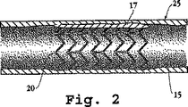
図2は、血管25における血管内の傷害部位でのステント20の配置を示す。この図は、その拡張した状態のステントであり、収縮した状態での部位への送達、及び薬物コーティングしたステント本体のフィラメントを血管17の壁に対して圧する程度までの放射状の拡張後のステントを示す。この配置により、ステントは血管内に固着され、薬物コーティングから血管を裏打ちする細胞に直接薬物を送達するために、ステントの外側表面の薬物コーティングを血管15を裏打ちする組織に直接接触させる。
FIG. 2 shows the placement of the
B.機械的な固着層
図3は、ステント20におけるフィラメント26の部分の拡大図である。フィラメントは、ステントが血管に操作可能に配置された場合に血管壁に面する、上部又は外部の表面33を有するフィラメント本体32を含む。フィラメントの上部表面上に形成され、又はそこに付着しているのは、液体注入可能な機械的な固着層34である。その微細構造に関すると、層34は、ノード36など、一連の突起又はノードを典型的に含む。固着層は、ステント上を運ばれた薬物層がステントのこの外側に面する側に局在するように、ステント本体フィラメントの外側の血管に面する側の上のみに形成されていることが好ましい。
B. Mechanical Bonding Layer FIG. 3 is an enlarged view of the
ステント(フィラメント)本体は、例えば、コバルト/クロム、ステンレススチール、又はプラチナ/イリジウムから形成され得る。液体注入可能な機械的な固着層は、例えば、ステント本体上に固着層を電気めっきすることにより、緊密にマッチさせた金属又は合金の類似物から構成され得る。 The stent (filament) body may be formed from, for example, cobalt / chromium, stainless steel, or platinum / iridium. The liquid injectable mechanical anchoring layer can be composed of a closely matched metal or alloy analog, for example, by electroplating the anchoring layer on the stent body.
図4は、その外側(外側に面している)表面上に形成された例示の機械的な固着層を有するステントフィラメントの一部分を示す、約100倍の倍率の顕微鏡写真である。見てとれるように、表面は高度に不規則であり、一かたまりの不規則な形状の表面のノード又は突起から形成された注入可能な表面層を提供している。図5に最もよく見られるように、これらの表面の突起は、外見はカリフラワー様であり、平均サイズが2〜8ミクロンのサイズ範囲、アンダーカット表面を有し、例えば毛管現象により、薬物溶液を層中に注入させる間隙を一連の突起間に形成する。層の厚さは、ステント本体からの平均の厚さとして測定して、少なくとも3ミクロンが好ましく、約3〜10ミクロンが典型的である。突起の合間の、又は間の間隙は不規則であり、いくつかの隣接する突起にわたって延びることができる。注入可能な表面層の空隙容量は、層の全体積の、約10〜50%の間が好ましく、約20〜40%がより典型的である。 FIG. 4 is a photomicrograph at about 100 × magnification showing a portion of a stent filament having an exemplary mechanical anchoring layer formed on its outer (outward facing) surface. As can be seen, the surface is highly irregular, providing an injectable surface layer formed from a cluster of irregularly shaped surface nodes or protrusions. As best seen in FIG. 5, these surface protrusions are cauliflower-like in appearance and have an undercut surface with an average size ranging from 2 to 8 microns, for example, by capillary action A gap to be injected into the layer is formed between the series of protrusions. The layer thickness is preferably at least 3 microns, typically about 3 to 10 microns, measured as an average thickness from the stent body. The gap between or between the protrusions is irregular and can extend over several adjacent protrusions. The void volume of the injectable surface layer is preferably between about 10-50% and more typically about 20-40% of the total volume of the layer.
上記に記載した、機械的な固着層は、ステント及び金属めっきの源、例えばプラチナ棒が、系の2つの電極として働く電気めっき方法により形成されるのが好ましい。従来の電気めっき方法では、2つの電極間に適用された電流は比較的低く、一様且つ制御された方法でめっきを形成させ、したがって光沢のある、鏡様の表面の滑らかな表面を形成する。しかし、電気めっきの電流が増大すると形成されためっき部はより不規則となり、図5に見られるもののように不規則なサイズ及び形状の突起をもたらす。 The mechanical anchoring layer described above is preferably formed by an electroplating method in which a stent and a source of metal plating, such as a platinum rod, serve as the two electrodes of the system. In conventional electroplating methods, the current applied between the two electrodes is relatively low, allowing the plating to be formed in a uniform and controlled manner, thus creating a smooth surface with a shiny, mirror-like surface. . However, as the electroplating current increases, the formed plating becomes more irregular, resulting in irregular size and shape protrusions as seen in FIG.
望ましい厚さ及び表面構造を達成する電気めっきのための方法は、当業者であれば知っている。1つの例示的な方法では、プラチナのステント(陰極)及びプラチナ棒(陽極)を、従来のめっき装置で電極として用い、槽としてTechnic,Inc(Anaheim、カリフォルニア州)からのプラチナAP RTUを、図4〜5に示す得られた固着層と共に使用した。槽の温度を160°F(71℃)に、及び適用した電圧を2.5ボルトに調節し、全めっき時間は15分であった。少なくとも1つの槽の温度、電圧、及び全めっき時間は、固着層に望ましい厚さ及び構造を達成するように調節することができることが理解されよう。 One skilled in the art knows methods for electroplating to achieve the desired thickness and surface structure. In one exemplary method, a platinum stent (cathode) and platinum rod (anode) are used as electrodes in a conventional plating apparatus, and a platinum AP RTU from Technic, Inc (Anaheim, Calif.) As a bath is illustrated. Used with the resulting anchoring layer shown in 4-5. The bath temperature was adjusted to 160 ° F. (71 ° C.) and the applied voltage to 2.5 volts, with a total plating time of 15 minutes. It will be appreciated that the temperature, voltage, and total plating time of the at least one bath can be adjusted to achieve the desired thickness and structure for the anchoring layer.
微細構造が様々で、様々な方法で形成された、様々な機械的な固着層が、本発明に適することが理解されよう。薬物層をステント上に固着することができる微細構造を固着層が有し、したがってステントが配置されている間、ステントがその収縮した状態から拡張した状態に拡張する場合に層が完全なままであることが必要であるにすぎない。他のタイプの固着層及びそれらの形成方法について以下に論じる。 It will be appreciated that a variety of mechanical anchoring layers having various microstructures and formed in a variety of ways are suitable for the present invention. The anchoring layer has a microstructure that can anchor the drug layer onto the stent, so that the layer remains intact as the stent expands from its contracted state to an expanded state while the stent is in place. It just needs to be. Other types of anchoring layers and methods for forming them are discussed below.
あるタイプの固着層は、高電流の条件下でマイクロプレーティング(microplating)により、例えば、金マイクロプレートにより形成された、一連の不規則な形状の突起、又は網状の微細構造を有する。電気めっき層は、例えば1〜5ミクロンのサイズ範囲の不規則な形状の粒子の層又はスタックとなり、表面に塗付された液体を吸収するその能力においてぎっしり詰まった砂に似ている粒子ふるい様を形成することがある。表面の小結節の形成につながる急速な堆積の条件下で、表面のコーティングをステントフィラメント上に蒸着し、又はスパッタリングすることにより、網状の表面を形成することもできる。 One type of anchoring layer has a series of irregularly shaped protrusions or network-like microstructures formed by microplating under high current conditions, for example by gold microplates. The electroplating layer is a layer or stack of irregularly shaped particles, for example in the 1-5 micron size range, and is a particle sieve-like that closely resembles packed sand in its ability to absorb the liquid applied to the surface. May form. A reticulated surface can also be formed by evaporating or sputtering a surface coating onto the stent filaments under conditions of rapid deposition leading to the formation of surface nodules.
別の一実施形態では、ステントの外側表面をエッチングして不規則な空隙を形成することにより、凹みを含む表面を形成する。空隙が相互に接続し、固着層内に間隙を形成していることが好ましい。このタイプの表面の層は、追加の材料の表面への堆積によりステント表面に形成されたものではなく、ステント本体の外側表面領域に形成されたものを説明するものである。金属表面の不規則なエッチングを生成するための方法は知られている。或いは、米国特許第6,274,294号、及び第6,019,784号に記載されているような、微細構造を形成する写真平版の方法を使用することができる。 In another embodiment, the outer surface of the stent is etched to form irregular voids to form a surface that includes indentations. It is preferable that the voids are connected to each other to form a gap in the fixed layer. This type of surface layer describes what was formed on the outer surface area of the stent body, not what was formed on the stent surface by deposition of additional material on the surface. Methods for generating irregular etching of metal surfaces are known. Alternatively, photolithographic methods of forming microstructures such as those described in US Pat. Nos. 6,274,294 and 6,019,784 can be used.
さらに別のアプローチでは、小型粒子、例えば1〜5ミクロンのサイズ範囲の焼結した粒子をステント表面に施し、焼結などでそこに固定することができる。このアプローチでは、焼結過程の間に熱分解により除去することができる適切な接着剤で、粒子を施すことができる。粒子を連続的に施すことにより、層を形成することができる。 In yet another approach, small particles, such as sintered particles in the 1-5 micron size range, can be applied to the stent surface and secured thereto by sintering or the like. In this approach, the particles can be applied with a suitable adhesive that can be removed by pyrolysis during the sintering process. A layer can be formed by applying the particles continuously.
C.薬物コーティング
再び図3を参照すると、本発明のステントにおける薬物コーティングは、39で概ね示され、ステントが血管傷害の部位で放射状に拡張する場合にステント本体上にコーティングを保持するための、固着層に注入された基層35、及び、ステントを配置する際血管壁と直接接触させる、実質的に連続した薬物の表面層37を有する。上記のセクションから理解できるように、薬物コーティングの基層には、固着層との一体的な粘着をもたらすために、ステントの固着層内に樹状の突起があるのが好ましいが、例えば、凹み内の固着層又は表面小結節間におけるアンダーカットの充填の領域のため、いずれの場合も、固着層の微細構造と「連動して」いる。この連動は、ステントの拡張の間、薬物コーティングの部分が分離し、ステントからはげ落ちるのを防ぐ上で重要である。
C. Drug Coating Referring again to FIG. 3, the drug coating in the stent of the present invention is generally indicated at 39 and is an anchoring layer for retaining the coating on the stent body when the stent expands radially at the site of vascular injury. And a substantially continuous surface layer 37 of drug that is in direct contact with the vessel wall when the stent is deployed. As can be seen from the above section, the drug coating base layer preferably has dendritic protrusions in the anchoring layer of the stent in order to provide integral adhesion with the anchoring layer, for example, in the recess. In each case, it is “in conjunction” with the microstructure of the anchoring layer because of the area of undercut filling between the anchoring layer or the surface nodules. This interlock is important in preventing drug coating portions from separating and flaking off the stent during stent expansion.
表面層37は、固着基層と一体的に形成され、図示するように、ステント配置後にそこから薬物が放出される薬物の連続した広がりを形成する。表面層は、約3〜10ミクロンが典型的である固着基層の厚さと比べると、厚さ約5〜30ミクロン又はそれを超えるのが典型的である。2つの層における薬物の相対的な量は、典型的には約20:1から1:1であり、より典型的には約10:1から4:1であり、この場合、コーティングの基層は全薬物コーティングの約10〜50%、好ましくは約25%以下構成する。したがって、コーティングからの薬物の放出の大部分は、連続した外側の層から生じ、この場合、薬物放出の動態は、コーティングにおける薬物の性質のみにより、且つ、場合により、薬物コーティングの全体の疎水性の性質を変えることがあるコーティングにおける添加物により決定される。 The surface layer 37 is formed integrally with the anchoring base layer and forms a continuous spread of drug from which the drug is released after stent placement, as shown. The surface layer is typically about 5-30 microns thick or greater compared to the thickness of the anchoring base layer, which is typically about 3-10 microns. The relative amount of drug in the two layers is typically about 20: 1 to 1: 1, more typically about 10: 1 to 4: 1, where the base layer of the coating is About 10-50% of the total drug coating, preferably about 25% or less. Thus, the majority of drug release from the coating arises from the continuous outer layer, where the kinetics of drug release is due solely to the nature of the drug in the coating, and in some cases the overall hydrophobicity of the drug coating. Determined by additives in the coating that may change the properties of the coating.
本発明では、タキソール(パクリタキセル)などの抗増殖薬、アンチセンス化合物、ドキソルビシン、及び最も詳しくは、以下に示す一般構造を有し、また一般的に「リムス(limus)」化合物と呼ばれる大環状トリエン免疫抑制化合物を含め、様々な抗再狭窄化合物を使用することができる。後者のクラスの化合物のいくつか、及びそれらの合成については、例えば、米国特許第4,650,803号、第5,288,711号、第5,516,781号、第5,665,772号、及び第6,153,252号、PCT公開第WO97/35575号、米国特許第6,273,913号B1、並びに、米国特許出願第60/176086号、第2000/021217号A1、及び第2001/002935号A1に記載されている。例示的な、大環状トリエン免疫抑制化合物は、形態:
[式中、
(i)Rは、H、直鎖又は分枝の短鎖アルキル、アルキルアルコール、アルキルエーテル、又は10個以下の炭素原子を含むアルダール基である]
を有する。例示の化合物では、RはCH2−X−OHであり、Xは炭素原子1から10個を含む直鎖若しくは分枝のアルキル基、又は(CH2)n−O−(CH2)nであり、nが1〜3であり、例えば、(CH2)2−O−(CH2)2である(本明細書ではBiolimusA−9とも呼ばれる)。
In the present invention, an antiproliferative drug such as taxol (paclitaxel), an antisense compound, doxorubicin, and most particularly a macrocyclic triene having the general structure shown below and also commonly referred to as a “limus” compound A variety of anti-restenosis compounds can be used, including immunosuppressive compounds. Some of the latter class of compounds and their synthesis are described, for example, in US Pat. Nos. 4,650,803, 5,288,711, 5,516,781, and 5,665,772. And US Pat. No. 6,153,252, PCT Publication No. WO 97/35575, US Pat. No. 6,273,913 B1, and US Patent Application Nos. 60/176086, 2000/021217 A1, and 2001/002935 A1. Exemplary macrocyclic triene immunosuppressive compounds are in the form:
[Where:
(I) R is H, linear or branched short chain alkyl, alkyl alcohol, alkyl ether, or an aldar group containing up to 10 carbon atoms]
Have In exemplary compounds, R is CH 2 —X—OH, and X is a linear or branched alkyl group containing 1 to 10 carbon atoms, or (CH 2 ) n —O— (CH 2 ) n There, n is 1-3, for example, (also referred to as BiolimusA-9 herein) (CH 2) 2 -O- ( CH 2) 2.
企図される別の薬物は、主にインスリン抵抗性を低減することにより作用する経口抗糖尿病薬であるピオグリタゾンである。この化合物は、in vitroで平滑筋細胞の成長因子誘導性の増殖を抑制し、バルーンの血管形成術が引き起こす血管傷害後の内膜の過形成を低減することが示されている。この化合物は、エタノール及びアセトンにわずかに可溶であり、水に不溶である。 Another contemplated drug is pioglitazone, an oral antidiabetic that works primarily by reducing insulin resistance. This compound has been shown to inhibit growth factor-induced proliferation of smooth muscle cells in vitro and reduce intimal hyperplasia after vascular injury caused by balloon angioplasty. This compound is slightly soluble in ethanol and acetone and insoluble in water.
別の適切な化合物は、赤血球の誘導に関わるポリペプチドであるエリスロポエチン(EPO)である。EPOは、動物モデルで、内皮の前駆細胞の動員を刺激することが示されており、梗塞した心臓における保護効果も表している。 Another suitable compound is erythropoietin (EPO), a polypeptide involved in the induction of red blood cells. EPO has been shown to stimulate the recruitment of endothelial progenitor cells in animal models and also represents a protective effect in the infarcted heart.
コーティングは、最初の血管傷害、ステントの存在により刺激されることがある凝固などの血液に関連する現象を最小にするのに有効な、又は傷害部位で血管の治癒を向上させるのに有効な第2の生理活性物質をさらに含むことができる。例示的な第2の物質には、可溶性な結晶の形態の、抗血小板薬、繊維素溶解薬、又は血栓溶解薬が含まれる。例示的な抗血小板薬、繊維素溶解薬、又は血栓溶解薬は、ヘパリン、アスピリン、ヒルジン、チクロピジン、エプチフィバチド、ウロキナーゼ、ストレプトキナーゼ、組織プラスミノーゲン活性化物質(TPA)、又はこれらの混合物である。 The coating is effective in minimizing blood-related phenomena such as initial vascular injury, coagulation that may be stimulated by the presence of the stent, or effective in improving vascular healing at the site of injury. Two physiologically active substances can be further included. Exemplary second materials include antiplatelet agents, fibrinolytic agents, or thrombolytic agents in the form of soluble crystals. Exemplary antiplatelet agents, fibrinolytic agents, or thrombolytic agents are heparin, aspirin, hirudin, ticlopidine, eptifibatide, urokinase, streptokinase, tissue plasminogen activator (TPA), or mixtures thereof. .
コーティングは、薬物コーティングの組織溶解性を最適化するように、薬物コーティングにおける望ましい粘着性を生じるように、及び埋め込まれたステントにおいて望ましい薬物放出速度を生じるように設計された結合剤、又は小分子を含むこともできる。溶解性の一態様では、薬物の疎水性は、典型的には、オクタノールと水の間のlogP(対数の分配係数)で表され、logP値>4は、典型的に組織における親油性結合部位に強力に引き付けられる(すなわち、溶解性である)、水及び血液に十分溶けない化合物を示している。logP値を決定するための変更されたHPLC法を用いて(Lombardoら、J.Med Chem.、43巻、2922頁、2000年)、本発明を支持して行った実験では、数々の上記のリムス及び他の化合物に対するlopP値を判定してきた。これらは、パラマイシン(R=H上記)に対する6.51から、エベロリムス(R=CH2−CH2−OH、上記)に対する6.70、Biolimus A9(R=(CH2)2−O−(CH2)2、上記)に対する7.63、及びパクリタキセルに対する4.68の範囲である。 The coating is a binder or small molecule designed to optimize the tissue solubility of the drug coating, to produce the desired adhesion in the drug coating, and to produce the desired drug release rate in the implanted stent Can also be included. In one aspect of solubility, the hydrophobicity of a drug is typically expressed in log P (logarithmic partition coefficient) between octanol and water, and log P values> 4 are typically lipophilic binding sites in tissues. It is a compound that is strongly attracted to (i.e., soluble) and is not sufficiently soluble in water and blood. Experiments conducted in support of the present invention using a modified HPLC method to determine log P values (Lombardo et al., J. Med Chem., 43 , 2922, 2000) The lopP values for Limus and other compounds have been determined. These are 6.70 from 6.51 for the para puromycin (R = H above), for everolimus (R = CH 2 -CH 2 -OH , the), Biolimus A9 (R = ( CH 2) 2 -O- ( CH 2) 2, in the range of 4.68 7.63, and to paclitaxel against above).
一般的に、ステント周囲の組織における高い溶解性、血液による薬物コーティングの洗い流しを防ぐための水における低い溶解性、及び薬物コーティングに対する一体性又は粘着性をもたらすために、特にステント埋め込み後のコーティングにおける2つの層間のコーティングの構造上の一体性を維持するために、抗再狭窄化合物のlogP値は比較的高く、例えば4を超えることが望ましい。或いは、薬物コーティングは、疎水性分子、例えば、レシチンなどの脂質分子、又は組織に粘着力及び改良された溶解性をもたらすための他の結合剤若しくは担体を含むように調合することができる。逆に言えば、化合物が非常に疎水性である結果コーティングからのその放出速度が非常に遅い場合、コーティングを比較的親水性の分子、例えば、短鎖ポリエチレングリコールなどと調合して薬物の放出速度を速めることができる。 Generally, especially in coatings after stent implantation to provide high solubility in the tissue surrounding the stent, low solubility in water to prevent blood drug washout, and integrity or adhesion to the drug coating. In order to maintain the structural integrity of the coating between the two layers, the log P value of the anti-restenosis compound is relatively high, for example greater than 4. Alternatively, the drug coating can be formulated to include hydrophobic molecules, eg, lipid molecules such as lecithin, or other binders or carriers to provide adhesion and improved solubility to the tissue. Conversely, if the compound is very hydrophobic and its release rate from the coating is very slow, the coating can be formulated with a relatively hydrophilic molecule, such as a short chain polyethylene glycol, to release the drug. Can speed up.
図7は、プラチナコーティングしたステント(プラチナめっきした固着層)上のBiolimusA−9(252μg)での、34日間にわたる薬物放出速度のカーブを示している。見てとれるように、約3分の1の薬物が、34日目までにステントから溶出される。in vivoにおける細胞膜の環境の疎水性が大きいので、in vivoにおける実際の薬物放出速度はさらにより速く、例えば、放出される大量の薬物が埋め込み後最初の数日間以内に放出されることが理解されよう。しかし、純粋に水性の媒体におけるin vitroの放出は、in vivoにおける効果的な薬物放出速度を達成し、また、望ましい薬物−層の粘着性を達成するために、薬物コーティングを調合するのに有用な基準を提供する。
FIG. 7 shows the drug release rate curve over 34 days with Biolimus A-9 (252 μg) on a platinum coated stent (platinum plated anchor layer). As can be seen, about one third of the drug is eluted from the stent by
好ましいコーティングは、少なくとも約90重量%の再狭窄抑制薬、及び最高10重量%の、結合剤又は放出速度を最適化するための薬剤などの添加物を含む。コーティングは、親水性の添加物としてのポリエチレングリコール、ヘパリン、又はEPOなどの溶質のポリマー種を含むことができるが、コーティングは、コーティングに構造的な支持を提供することができる架橋されているポリマーを実質的に含まない。 Preferred coatings include at least about 90% by weight restenosis-inhibiting agent and up to 10% by weight of additives such as binders or agents to optimize release rate. The coating can include solute polymer species such as polyethylene glycol, heparin, or EPO as a hydrophilic additive, but the coating is a crosslinked polymer that can provide structural support to the coating. Is substantially not included.
D.ステントコーティング方法
図6は、薬物コーティングをステントフィラメント50の固着層上に堆積させるのに有用なロボット装置を示している。再狭窄抑制薬、及びあらゆる他のコーティング成分を適切な溶剤に溶解することにより、薬物溶液又は混合物40を作成する。リムス化合物などの疎水性化合物を堆積させるための好ましい溶剤の1つは、薬物濃度が約25〜100mg/mlの間、典型的には約50mg/mlの酢酸エチルである。酢酸メチル又は酢酸プロピルなどの、他の低級アルキル酢酸エステルも適切であり、化合物を指摘された濃度で溶解することができる数々の他の溶剤も適切であり得る。典型的には、溶剤混合物の粘性は、約2センチポアズから約2000センチポアズの範囲の溶剤の量を変化させることにより調製し、典型的には約50から700センチポアズであることができる。所望により、ポリマー分子を加えて溶液の粘性を増大させてもよい。
D. Stent Coating Method FIG. 6 shows a robotic device useful for depositing a drug coating on the anchoring layer of
薬物溶液を加圧可能な貯蔵槽42に配置する。貯蔵槽に、液体加圧ポンプ44を接続する。加圧ポンプは、溶液送達チューブ46によりプログラムされた速度で溶剤混合物を動くよう促すことができるあらゆる圧力源であることができる。精密分配システムの技術分野ではよく知られているように、圧力ポンプ44はマイクロコントローラー(図示せず)の制御下にある。例えば、このようなマイクロコントローラーは、I&J Fisnar Inc.(Fair Lawn、ニュージャージー州)から入手可能な、4−Axis Dispensing Robot Model、I&J500−R番及びI&J750−R番を含むことができ、このどちらも、パーソナルコンピュータ、又はAsymtek(Carlsbad、カリフォルニア州)から入手可能なAutomoveA−400などの精密分配システムにより、RS−232C 通信インターフェースを介して制御可能である。RS232Cインターフェースを制御するための適切なソフトウェアプログラムは、やはりAsymtek Inc(Carlsbad、カリフォルニア州)から入手可能な、Fluidmoveシステムを含むことができる。
The drug solution is placed in a
貯蔵槽42に取り付けて、例えば、貯蔵槽の底部に、溶剤混合物をステントの表面に送達するための溶液送達チューブ48がある。加圧可能な貯蔵槽42及び送達チューブ48は、溶剤送達チューブを、1ステップにつき0.2mmなどの小さいステップで、又は矢印X1が示すようにステントの長軸に沿って継続的に動かすことができる、可動の支持(図示せず)に搭載されている。加圧可能な貯蔵槽42及び送達チューブ48に対する可動の支持は、マイクロフィラメントの表面により近い、又は矢印Y1が示すように小ステップでマイクロフィラメント表面から上方に離れている送達チューブのチップ(遠位端)を動かすこともできる。
There is a
コーティングされていないステントは、少なくとも1端のステントの内側表面に接触している回転チャックにより把握される。このやり方で、ステントを、R1に見られるように長軸に沿って回転することができる。当技術分野ではよく知られているようにステッパーモーターをチャックに取り付けることにより、送達チューブによりコーティングするためのステント構造の最上部の表面の位置を変えるために、ステントの軸方向回転は、小程度のステップ、例えば1ステップあたり0.5度で実現することができる。所望により、ステントを継続的に回転することができる。小体積の液体送達装置を正確に位置決めする方法は、X−Y−Z溶剤分配システムの技術分野ではよく知られており、本発明中に組み入れることができる。或いは、送達チューブを固定された位置に保持することができ、回転運動の他に、ステントをその長手方向に沿って動かしてコーティング過程を実現する。 The uncoated stent is grasped by a rotating chuck in contact with the inner surface of the stent at least at one end. In this manner, the stent can be rotated along the long axis as seen at R1. As is well known in the art, the axial rotation of the stent is minor to reposition the top surface of the stent structure for coating by the delivery tube by attaching a stepper motor to the chuck. For example, 0.5 degree per step. If desired, the stent can be continuously rotated. Methods for accurately positioning small volume liquid delivery devices are well known in the XYZ solvent dispensing system art and can be incorporated into the present invention. Alternatively, the delivery tube can be held in a fixed position, and in addition to rotational movement, the stent is moved along its length to achieve the coating process.
液体加圧ポンプの動作、液体送達チューブのX1及びY1の位置決め、並びにステントのR1の位置決めは、典型的にはデジタルコントローラー、及びコンピュータソフトウェアプログラムにより、正確に必要とされる量の溶液が、その上に溶剤が漏れることができるステントの表面上の任意の所望の場所に堆積するように調整される。最終の薬物層の厚さがステントの長さにわたって変化するように堆積を行うことができ、例えば、ステントの末端は、ステントの末端に局在することがある再狭窄効果を低減するためにより厚い薬物層を有することができる。同様に、ステント末端の側部領域をコーティングして、末端の効果を相殺することができる。 The operation of the liquid pressurization pump, the positioning of the liquid delivery tube X1 and Y1, and the positioning of the stent R1 are typically performed by a digital controller and a computer software program, with the exact amount of solution required. It is tailored to deposit at any desired location on the surface of the stent through which solvent can leak. Deposition can be performed so that the final drug layer thickness varies over the length of the stent, for example, the end of the stent is thicker to reduce restenosis effects that may be localized at the end of the stent It can have a drug layer. Similarly, the side region at the end of the stent can be coated to offset the end effect.
適切なX−Y−Zの位置決めの表及び可動の支持は、I&J Fisnar Inc(Fair Lawn、ニュージャージー州)から入手可能なものなど、市販されている。溶液送達チューブの好ましい寸法は、適切なロッキングコネクタに搭載した18〜28ゲージの間のステンレススチールハイポチューブが好ましい。このような送達チューブは、EFD Inc.(East Providence、ロードアイランド州)から入手することができる。EFDは、Special Purpose Tipsに関するセレクションガイドを発行している。好ましいチップは、5118−1/4B番から5121−1/4−B番の「長さ1/4”の、粒子を充填した、又は厚い材料をすばやく2地点間に分配するためのバリを含まない不動態化ステンレススチールチップ(Burr−free passivated stainless steel tips with 1/4” length for fast point−to−point dispensing of particle−filled or thick materials)」、51150VAL−B番の「平坦なリボン状の堆積の濃厚パスタ、シーラント、及びエポキシを施す楕円形ステンレススチールチップ(Oval stainless steel tips apply thick pastes,sealants,and epoxies in flat ribbon deposits)」、並びに5121−TLC−B番から5125−TLC−B番の「シアノアクリレートの目詰まりに抵抗し、低粘性溶液にさらなる堆積のコントロールをもたらす。圧着しテフロン(登録商標)で裏打ちしたもの(Resist clogging of cyanoacrylates and provides additional deposit control for low viscosity fluids.Crimped and Teflon lined)」であり、全てEFD Inc.(East Providence、ロードアイランド州)から入手することができる。あらゆる型番の市販のチップが、ロボット装置で使用するのに適することが理解されよう。EFD Inc.(East Providence、ロードアイランド州)から入手可能な在庫番号1000Y5148から1000Y5152Fなど、あらゆる番号の使い捨ての加圧可能な溶液貯蔵槽が適切であり、市販されている。本発明で使用するための代替のチップは、VWRカタログ番号15401〜560番の「Microhematocrit Tubes」長さ60mm、内径0.5〜0.6mmで入手可能である、内径が約0.0005から0.002インチ(0.0127から0.0508mm)、例えば約0.001インチ(0.0254mm)のガラス製マイクロキャピラリーである。チューブは、ブンゼンバーナー下でさらに引いて、薬物/溶剤混合物を正確に施すのに望ましい内径を達成することができる。2つ以上の液体分配チューブの型を協調して働かせて用いてコーティングを形成することができ、或いは代替的に様々なチップを装備し、又は同じ過程において様々な粘性の溶液若しくは様々な化学的組成からなる多数の溶液を含む、2つ以上の移動可能な溶液貯蔵槽を用いて、コーティングを形成することができることが理解されよう。 Suitable XYZ positioning tables and movable supports are commercially available, such as those available from I & J Fisnar Inc (Fair Lawn, NJ). The preferred size of the solution delivery tube is preferably a 18-28 gauge stainless steel hypotube mounted on a suitable locking connector. Such delivery tubes are available from EFD Inc. (East Providence, Rhode Island). EFD publishes a selection guide for Special Purpose Tips. Preferred tips include burrs to quickly distribute particle-filled or thick material between two points, from 5118-1 / 4B to 5121-1 / 4-B "length 1/4" No passivated stainless steel chip (Burr-free passivated steel tip tips with 1/4 "length for fast-pointing of part-of-particulate-filled-or-thick ribbon-51) Oval stainless steel tips apply thick pastes, sea with thick deposit pasta, sealant, and epoxy Ants, and epoxies in flat ribbon deposits) and 5121-TLC-B to 5125-TLC-B “resist cyanoacrylate clogging and provide additional control of deposition in low viscosity solutions. (Registered Trademark) Lined with Resisting of Cyanocrylates and Providies additional deposition control for low visibility fluids. Crimped and Teflon lined. (East Providence, Rhode Island). It will be appreciated that any number of commercially available chips are suitable for use in robotic devices. EFD Inc. Any number of disposable pressurizable solution reservoirs are suitable and commercially available, such as stock numbers 1000Y5148 to 1000Y5152F available from (East Providence, Rhode Island). An alternative chip for use in the present invention is available with a "Microhematocrit Tubes" length of 60 mm and an inner diameter of 0.5-0.6 mm, VWR catalog number 15401-560, with an inner diameter of about 0.0005-0. 0.002 inch (0.0127 to 0.0508 mm), for example, about 0.001 inch (0.0254 mm) glass microcapillaries. The tube can be further pulled under a Bunsen burner to achieve the desired inner diameter to accurately dispense the drug / solvent mixture. Two or more liquid distribution tube types can be used in concert to form a coating, or alternatively equipped with different tips, or with different viscous solutions or different chemicals in the same process. It will be appreciated that more than one movable solution reservoir can be used to form the coating, including multiple solutions of composition.
ステッパーモーターを操作するための適切なプログラム可能なマイクロコントローラー、及びXYZ表は、Asymtek,Incから入手できる。適切なチャック及びステッパーモーターのシステムは、Edmund Scientific(Barrington、ニュージャージー州)から入手できる。 A suitable programmable microcontroller for operating the stepper motor, and an XYZ table are available from Asymtek, Inc. A suitable chuck and stepper motor system is available from Edmund Scientific (Barrington, NJ).
典型的には、上記に記載したように、コーティングをある量でステントの外側の支持表面上に直接施して、乾燥時に、望ましい厚さの薬物層を生成する。薬物の溶液を塗付する際、一部分は機械的な固着層中に注入し、残りはフィラメントの最上部表面に沿って数珠状のリボンを形成する。コーティングの形成を完結するために、コーティング層を真空下で、例えば、20インチHg(50.8cmHg)で、硬化した、溶剤を含まない層を形成するまで乾燥させる。理想的には、この段階でコーティングがグラシン状の外観を呈し、望ましいコーティングの一体性を示す。グラシン状の外観を呈さないコーティング、又は外観が粉末状に見えるコーティングは適切でないと考えられ、薬物を、別の溶剤で、又はコーティングの粘着性を増強する添加物と組み合わせて塗付するべきであることが指摘される。 Typically, as described above, a certain amount of coating is applied directly onto the outer support surface of the stent to produce a drug layer of the desired thickness upon drying. As the drug solution is applied, a portion is poured into the mechanical anchoring layer and the remainder forms a beaded ribbon along the top surface of the filament. To complete the formation of the coating, the coating layer is dried under vacuum, eg, 20 inches Hg (50.8 cm Hg), until a cured, solvent-free layer is formed. Ideally, at this stage, the coating has a glassine-like appearance, indicating the desired coating integrity. Coatings that do not display a glassy appearance or appear to be powdery are considered inappropriate and should be applied with another solvent or in combination with an additive that enhances the tackiness of the coating. It is pointed out that there is.
コーティングのステント表面に対する十分な毛細管の引力が存在する場合、コーティングをステントに施す代替の方法は、ステントの全て又は部分を薬物溶液の貯蔵槽中に浸漬することであることができ、この際、薬物はコーティングの間隙中に引き上げられる。さらに、ステントに薬物溶液を噴霧してもよく、この際、薬物はコーティングの間隙中に引き込まれる。 If there is sufficient capillary attraction to the stent surface of the coating, an alternative method of applying the coating to the stent can be to immerse all or part of the stent in a reservoir of drug solution, where The drug is pulled up into the gap in the coating. In addition, the stent may be sprayed with a drug solution, with the drug being drawn into the gaps in the coating.
III.使用方法及び性能の特質
本セクションは、本発明による血管処置方法、及び本発明により構成されたステントの性能の特質を記載する。
III. Usage and Performance Characteristics This section describes the vascular treatment method according to the present invention and the performance characteristics of a stent constructed according to the present invention.
本発明の方法は、限局性の血管傷害を受けた患者、又は血管閉塞の危険性のある患者における再狭窄の危険性及び/又は程度を最小にするように設計されている。典型的には、血管傷害は、冠状動脈又は末梢の動脈血管などの部分的に閉塞した血管を開く血管造影の手法中に生じる。血管造影の手法では、閉塞部位にバルーンカテーテルを配置し、1回又は複数回、遠位末端のバルーンを膨張させ、収縮させて閉塞した血管を強制的に開く。この血管拡張は、プラークが除去され得る血管壁で表面の外傷を特に伴い、しばしば、炎症、ポジティブリモデリングをもたらす細胞の増殖、及び再狭窄により血管が経時的に反応するほどの限局的な傷害を生じる。再狭窄で知られるこのプロセスの発生又は重症度は、血管造影の手法により生じる血管の伸展及び傷害の程度に関連することが多いことは、驚くことではない。特に過度の伸展が35%又はそれを超える場合、再狭窄は高頻度で、しばしば実質的な重症度で起こる、すなわち血管閉塞である。 The methods of the present invention are designed to minimize the risk and / or extent of restenosis in patients who have suffered localized vascular injury or are at risk of vascular occlusion. Typically, vascular injury occurs during angiographic procedures that open partially occluded blood vessels, such as coronary or peripheral arterial blood vessels. In the angiographic technique, a balloon catheter is placed at the occlusion site, and the distal end balloon is inflated and deflated one or more times to forcibly open the occluded blood vessel. This vasodilation is especially accompanied by surface trauma at the vessel wall where plaque can be removed, often localized injury that causes the vessel to react over time due to inflammation, cell proliferation leading to positive remodeling, and restenosis Produce. It is not surprising that the occurrence or severity of this process, known as restenosis, is often related to the extent of vessel stretching and injury caused by angiographic techniques. Restenosis is frequent, often with substantial severity, i.e. vascular occlusion, especially when excessive stretching is 35% or above.
本発明を実践する際は、ステントをその収縮した状態で、典型的にはカテーテルの遠位末端に、カテーテル内腔内又は収縮した状態で遠位末端のバルーン上のどちらかに配置する。次いで、遠位のカテーテル末端を、傷害部位又は閉塞の可能性のある部位に導き、例えば、ステントが自動的に拡張する場合にはステントを部位内に放出するためのトリップワイヤを用いることにより、又はバルーンの膨張によりバルーン上のステントを拡張することにより、ステントが血管壁に接触し、事実上ステントを部位の組織壁中に埋め込むまで、カテーテルから放つ。ステントを部位に配備すると、ステントは直ちに、有効化合物を血管部位を裏打ちする細胞中に放出し始めて、細胞の増殖を抑制する。 In practicing the present invention, the stent is placed in its deflated state, typically at the distal end of the catheter, either within the catheter lumen or deflated, on the distal end balloon. The distal catheter end is then guided to the site of injury or potential occlusion, for example by using a trip wire to release the stent into the site if the stent automatically expands, Alternatively, by expanding the stent on the balloon by balloon inflation, the stent is released from the catheter until it contacts the vessel wall and is effectively embedded in the tissue wall at the site. When the stent is deployed at the site, the stent immediately begins to release the active compound into the cells lining the vascular site, inhibiting cell growth.
Schwartzら(「Restenosis After Balloon Angioplasty−A Practical Proliferative Model in Porcine Coronary Arteries」、Circulation、82巻(6)、2190〜2200頁、1990年)が概ね記載しているように、ブタ再狭窄動物モデルにおける試験が、本発明のステントが再狭窄の程度を低減する能力を立証している。手短に述べると、本発明を支持して行われた研究とステント埋め込み28日後の再狭窄の程度を、BiolimusA−9の薬物コーティングのある、又はなしの、電気めっきしたプラチナの固着層を有する金属ステントで比較した。薬物の存在が、再狭窄の程度を低減することが、28日間の研究の終りに観察された。 Schwartz et al. (“Restenosis After Balloon Angioplasty-A Practical Proliferative Model in Porcine Coronary Arteries”, Circulation, Vol . 82 (6), 2190 to 2200, 1990). Tests demonstrate the ability of the stent of the present invention to reduce the degree of restenosis. Briefly, studies conducted in support of the present invention and the degree of restenosis after 28 days of stent implantation were compared to metals with an electroplated platinum anchoring layer, with or without Biolimus A-9 drug coating. Comparison with stents. It was observed at the end of the 28 day study that the presence of the drug reduced the degree of restenosis.
前述から、非常に様々な本発明の目的及び特徴が満たされることを見てとることができる。ステントの表面上の薬物に対する貯蔵槽として用いられるポリマー−スリーブ材料が存在しないおかげで、ステント上の一定量の抗再狭窄薬に対してステントは低下したプロファイルを有する。このため、血管の開口は大きくなり、したがって血流は向上し、血管の伸展は少なくなる。 From the foregoing, it can be seen that a great variety of objects and features of the invention are met. Thanks to the absence of a polymer-sleeve material used as a reservoir for the drug on the surface of the stent, the stent has a reduced profile for a certain amount of anti-restenosis drug on the stent. This increases the opening of the blood vessel, thus improving blood flow and reducing blood vessel extension.
ポリマーのステントのコーティングは、血管壁の炎症の増大及び再狭窄を作り出すことが知られており、ポリマーの成分が存在しなければ血管部位での炎症及び刺激を低減し、この炎症及び刺激は、例えば、生分解性のポリマーの分解に対する炎症細胞の反応、又は安定なポリマーに対する外来の身体反応により引き起こされ得るものである。同時に、薬物放出の動力学はポリマーマトリックスを通した拡散、又は多孔性の外側の層全体への拡散、又はステントにおける多孔性の金属マトリックスからの拡散に依存せず、本質的に純粋な薬物コーティングから血管の環境中への薬物の溶解のみに頼っているので、本発明の薬物コーティングは、薬物の放出をより強力に制御し、経時的な放出速度をより一定させることができる。薬物コーティングが固着層まで減少して初めて、薬物放出の動態学が別の要因、この場合は機械的な固着層の多孔性により、少々影響を受けることがある。 Polymeric stent coatings are known to create increased inflammation and restenosis of the vessel wall, which reduces inflammation and irritation at the vascular site in the absence of polymer components, For example, it can be caused by an inflammatory cell response to degradation of a biodegradable polymer, or an exogenous body response to a stable polymer. At the same time, the kinetics of drug release is independent of diffusion through the polymer matrix, or throughout the porous outer layer, or from the porous metal matrix in the stent, and is essentially a pure drug coating Since it relies solely on dissolution of the drug from the blood vessel environment into the vascular environment, the drug coating of the present invention can more tightly control the release of the drug and provide a more constant rate of release over time. Only after the drug coating has been reduced to the anchoring layer can the drug release kinetics be slightly affected by another factor, in this case the mechanical anchoring layer porosity.
本発明を、特定の実施形態及び適用に関して記載してきたが、本発明から逸脱することなしに様々な変更及び修正を行うことができることが理解されよう。 Although the invention has been described with reference to particular embodiments and applications, it will be understood that various changes and modifications can be made without departing from the invention.
Claims (1)
連結されたフィラメントの格子構造を有するステント本体、及び
大環状トリエン免疫抑制化合物を含有するが、架橋されたポリマーを含有しない薬物コーティングであって、当該大環状トリエン免疫抑制化合物が、構造:
を含む、上記ステント。A radially expandable endovascular stent designed to be placed at the site of vascular injury ,
A stent body having a lattice structure of connected filaments ; and
A drug coating that contains a macrocyclic triene immunosuppressive compound, but does not contain a crosslinked polymer , wherein the macrocyclic triene immunosuppressive compound has the structure:
Including the stent .
Applications Claiming Priority (3)
| Application Number | Priority Date | Filing Date | Title |
|---|---|---|---|
| US61307104P | 2004-09-24 | 2004-09-24 | |
| US11/232,598 US7901451B2 (en) | 2004-09-24 | 2005-09-22 | Drug-delivery endovascular stent and method for treating restenosis |
| PCT/US2005/034193 WO2006036801A2 (en) | 2004-09-24 | 2005-09-23 | Drug-delivery endovascular stent and method for treating restenosis |
Related Child Applications (1)
| Application Number | Title | Priority Date | Filing Date |
|---|---|---|---|
| JP2007336802A Division JP4892471B2 (en) | 2004-09-24 | 2007-12-27 | Intravascular stent for drug delivery and method for treating restenosis |
Publications (3)
| Publication Number | Publication Date |
|---|---|
| JP2008514290A JP2008514290A (en) | 2008-05-08 |
| JP2008514290A5 JP2008514290A5 (en) | 2008-11-20 |
| JP4231089B2 true JP4231089B2 (en) | 2009-02-25 |
Family
ID=36100285
Family Applications (2)
| Application Number | Title | Priority Date | Filing Date |
|---|---|---|---|
| JP2007533660A Active JP4231089B2 (en) | 2004-09-24 | 2005-09-23 | Intravascular stent for drug delivery and method for treating restenosis |
| JP2007336802A Active JP4892471B2 (en) | 2004-09-24 | 2007-12-27 | Intravascular stent for drug delivery and method for treating restenosis |
Family Applications After (1)
| Application Number | Title | Priority Date | Filing Date |
|---|---|---|---|
| JP2007336802A Active JP4892471B2 (en) | 2004-09-24 | 2007-12-27 | Intravascular stent for drug delivery and method for treating restenosis |
Country Status (10)
| Country | Link |
|---|---|
| US (3) | US7901451B2 (en) |
| EP (2) | EP2123311B1 (en) |
| JP (2) | JP4231089B2 (en) |
| CN (2) | CN102283730B (en) |
| AT (2) | ATE446777T1 (en) |
| AU (1) | AU2005289741C1 (en) |
| DE (1) | DE602005017414D1 (en) |
| ES (1) | ES2333606T3 (en) |
| HK (2) | HK1105554A1 (en) |
| WO (1) | WO2006036801A2 (en) |
Families Citing this family (92)
| Publication number | Priority date | Publication date | Assignee | Title |
|---|---|---|---|---|
| US7713297B2 (en) | 1998-04-11 | 2010-05-11 | Boston Scientific Scimed, Inc. | Drug-releasing stent with ceramic-containing layer |
| US7220276B1 (en) * | 2000-03-06 | 2007-05-22 | Surmodics, Inc. | Endovascular graft coatings |
| US8741378B1 (en) | 2001-06-27 | 2014-06-03 | Advanced Cardiovascular Systems, Inc. | Methods of coating an implantable device |
| WO2003002243A2 (en) | 2001-06-27 | 2003-01-09 | Remon Medical Technologies Ltd. | Method and device for electrochemical formation of therapeutic species in vivo |
| US7169178B1 (en) * | 2002-11-12 | 2007-01-30 | Advanced Cardiovascular Systems, Inc. | Stent with drug coating |
| JP2006527628A (en) * | 2003-06-16 | 2006-12-07 | ナンヤン・テクノロジカル・ユニバーシティー | Stent of polymer material and manufacturing method |
| US8137397B2 (en) * | 2004-02-26 | 2012-03-20 | Boston Scientific Scimed, Inc. | Medical devices |
| US8003122B2 (en) * | 2004-03-31 | 2011-08-23 | Cordis Corporation | Device for local and/or regional delivery employing liquid formulations of therapeutic agents |
| US7901451B2 (en) | 2004-09-24 | 2011-03-08 | Biosensors International Group, Ltd. | Drug-delivery endovascular stent and method for treating restenosis |
| US7815926B2 (en) * | 2005-07-11 | 2010-10-19 | Musculoskeletal Transplant Foundation | Implant for articular cartilage repair |
| US20070112421A1 (en) * | 2005-11-14 | 2007-05-17 | O'brien Barry | Medical device with a grooved surface |
| US8840660B2 (en) | 2006-01-05 | 2014-09-23 | Boston Scientific Scimed, Inc. | Bioerodible endoprostheses and methods of making the same |
| US8089029B2 (en) | 2006-02-01 | 2012-01-03 | Boston Scientific Scimed, Inc. | Bioabsorbable metal medical device and method of manufacture |
| US20070224235A1 (en) | 2006-03-24 | 2007-09-27 | Barron Tenney | Medical devices having nanoporous coatings for controlled therapeutic agent delivery |
| US8187620B2 (en) | 2006-03-27 | 2012-05-29 | Boston Scientific Scimed, Inc. | Medical devices comprising a porous metal oxide or metal material and a polymer coating for delivering therapeutic agents |
| US8048150B2 (en) | 2006-04-12 | 2011-11-01 | Boston Scientific Scimed, Inc. | Endoprosthesis having a fiber meshwork disposed thereon |
| WO2007140320A2 (en) * | 2006-05-26 | 2007-12-06 | Nanyang Technological University | Implantable article, method of forming same and method for reducing thrombogenicity |
| US8815275B2 (en) | 2006-06-28 | 2014-08-26 | Boston Scientific Scimed, Inc. | Coatings for medical devices comprising a therapeutic agent and a metallic material |
| WO2008002778A2 (en) | 2006-06-29 | 2008-01-03 | Boston Scientific Limited | Medical devices with selective coating |
| WO2008017028A2 (en) | 2006-08-02 | 2008-02-07 | Boston Scientific Scimed, Inc. | Endoprosthesis with three-dimensional disintegration control |
| WO2008033711A2 (en) | 2006-09-14 | 2008-03-20 | Boston Scientific Limited | Medical devices with drug-eluting coating |
| ES2368125T3 (en) | 2006-09-15 | 2011-11-14 | Boston Scientific Scimed, Inc. | BIOEROSIONABLE ENDOPROOTHESIS WITH BIOESTABLE INORGANIC LAYERS. |
| US8057534B2 (en) | 2006-09-15 | 2011-11-15 | Boston Scientific Scimed, Inc. | Bioerodible endoprostheses and methods of making the same |
| JP2010503485A (en) | 2006-09-15 | 2010-02-04 | ボストン サイエンティフィック リミテッド | Medical device and method for manufacturing the same |
| JP2010503489A (en) | 2006-09-15 | 2010-02-04 | ボストン サイエンティフィック リミテッド | Biodegradable endoprosthesis and method for producing the same |
| CA2663762A1 (en) | 2006-09-18 | 2008-03-27 | Boston Scientific Limited | Endoprostheses |
| US8067055B2 (en) * | 2006-10-20 | 2011-11-29 | Biosensors International Group, Ltd. | Drug-delivery endovascular stent and method of use |
| CN101663054B (en) * | 2006-10-20 | 2013-08-07 | 生物传感器国际集团有限公司 | Drug-delivery endovascular stent and method of use |
| US20080097591A1 (en) * | 2006-10-20 | 2008-04-24 | Biosensors International Group | Drug-delivery endovascular stent and method of use |
| US20080103584A1 (en) * | 2006-10-25 | 2008-05-01 | Biosensors International Group | Temporal Intraluminal Stent, Methods of Making and Using |
| US7981150B2 (en) | 2006-11-09 | 2011-07-19 | Boston Scientific Scimed, Inc. | Endoprosthesis with coatings |
| US20090062910A1 (en) * | 2006-11-16 | 2009-03-05 | Shippy Iii James Lee | Stent with differential timing of abluminal and luminal release of a therapeutic agent |
| CN101199873B (en) * | 2006-12-14 | 2013-06-19 | 乐普(北京)医疗器械股份有限公司 | Medicament elution instrument nanometer class colon washer machineole drug releasing structure and preparing method thereof |
| EP2277563B1 (en) | 2006-12-28 | 2014-06-25 | Boston Scientific Limited | Bioerodible endoprostheses and method of making the same |
| US8431149B2 (en) | 2007-03-01 | 2013-04-30 | Boston Scientific Scimed, Inc. | Coated medical devices for abluminal drug delivery |
| US8070797B2 (en) | 2007-03-01 | 2011-12-06 | Boston Scientific Scimed, Inc. | Medical device with a porous surface for delivery of a therapeutic agent |
| US8067054B2 (en) | 2007-04-05 | 2011-11-29 | Boston Scientific Scimed, Inc. | Stents with ceramic drug reservoir layer and methods of making and using the same |
| WO2008125940A2 (en) * | 2007-04-17 | 2008-10-23 | Pfizer Products Inc. | Nanoparticles comprising non-crystalline drug |
| US7976915B2 (en) | 2007-05-23 | 2011-07-12 | Boston Scientific Scimed, Inc. | Endoprosthesis with select ceramic morphology |
| US7942926B2 (en) | 2007-07-11 | 2011-05-17 | Boston Scientific Scimed, Inc. | Endoprosthesis coating |
| US8002823B2 (en) | 2007-07-11 | 2011-08-23 | Boston Scientific Scimed, Inc. | Endoprosthesis coating |
| JP2010533563A (en) | 2007-07-19 | 2010-10-28 | ボストン サイエンティフィック リミテッド | Endoprosthesis with adsorption inhibiting surface |
| US7931683B2 (en) | 2007-07-27 | 2011-04-26 | Boston Scientific Scimed, Inc. | Articles having ceramic coated surfaces |
| US8815273B2 (en) | 2007-07-27 | 2014-08-26 | Boston Scientific Scimed, Inc. | Drug eluting medical devices having porous layers |
| US8221822B2 (en) | 2007-07-31 | 2012-07-17 | Boston Scientific Scimed, Inc. | Medical device coating by laser cladding |
| JP2010535541A (en) | 2007-08-03 | 2010-11-25 | ボストン サイエンティフィック リミテッド | Coating for medical devices with large surface area |
| JP2009050513A (en) * | 2007-08-28 | 2009-03-12 | Olympus Medical Systems Corp | Stent and stent delivery system |
| US8052745B2 (en) | 2007-09-13 | 2011-11-08 | Boston Scientific Scimed, Inc. | Endoprosthesis |
| US20090076591A1 (en) * | 2007-09-19 | 2009-03-19 | Boston Scientific Scimed, Inc. | Stent Design Allowing Extended Release of Drug and/or Enhanced Adhesion of Polymer to OD Surface |
| US20100298925A1 (en) * | 2007-10-31 | 2010-11-25 | Chameleon Scientific Corporation | Spinulose metal surfaces |
| US8216632B2 (en) | 2007-11-02 | 2012-07-10 | Boston Scientific Scimed, Inc. | Endoprosthesis coating |
| US7938855B2 (en) | 2007-11-02 | 2011-05-10 | Boston Scientific Scimed, Inc. | Deformable underlayer for stent |
| US8029554B2 (en) | 2007-11-02 | 2011-10-04 | Boston Scientific Scimed, Inc. | Stent with embedded material |
| AU2008322469B2 (en) | 2007-11-14 | 2014-02-20 | Biosensors International Group, Ltd. | Automated coating apparatus and method |
| US7833266B2 (en) | 2007-11-28 | 2010-11-16 | Boston Scientific Scimed, Inc. | Bifurcated stent with drug wells for specific ostial, carina, and side branch treatment |
| JP5581311B2 (en) | 2008-04-22 | 2014-08-27 | ボストン サイエンティフィック サイムド,インコーポレイテッド | MEDICAL DEVICE HAVING INORGANIC MATERIAL COATING AND MANUFACTURING METHOD THEREOF |
| WO2009132176A2 (en) | 2008-04-24 | 2009-10-29 | Boston Scientific Scimed, Inc. | Medical devices having inorganic particle layers |
| US7998192B2 (en) | 2008-05-09 | 2011-08-16 | Boston Scientific Scimed, Inc. | Endoprostheses |
| US8236046B2 (en) | 2008-06-10 | 2012-08-07 | Boston Scientific Scimed, Inc. | Bioerodible endoprosthesis |
| WO2009155328A2 (en) | 2008-06-18 | 2009-12-23 | Boston Scientific Scimed, Inc. | Endoprosthesis coating |
| US8206635B2 (en) | 2008-06-20 | 2012-06-26 | Amaranth Medical Pte. | Stent fabrication via tubular casting processes |
| US8206636B2 (en) | 2008-06-20 | 2012-06-26 | Amaranth Medical Pte. | Stent fabrication via tubular casting processes |
| US10898620B2 (en) | 2008-06-20 | 2021-01-26 | Razmodics Llc | Composite stent having multi-axial flexibility and method of manufacture thereof |
| US7951193B2 (en) * | 2008-07-23 | 2011-05-31 | Boston Scientific Scimed, Inc. | Drug-eluting stent |
| US7985252B2 (en) | 2008-07-30 | 2011-07-26 | Boston Scientific Scimed, Inc. | Bioerodible endoprosthesis |
| US8382824B2 (en) | 2008-10-03 | 2013-02-26 | Boston Scientific Scimed, Inc. | Medical implant having NANO-crystal grains with barrier layers of metal nitrides or fluorides |
| US8231980B2 (en) | 2008-12-03 | 2012-07-31 | Boston Scientific Scimed, Inc. | Medical implants including iridium oxide |
| US8267992B2 (en) | 2009-03-02 | 2012-09-18 | Boston Scientific Scimed, Inc. | Self-buffering medical implants |
| US8071156B2 (en) | 2009-03-04 | 2011-12-06 | Boston Scientific Scimed, Inc. | Endoprostheses |
| US8287937B2 (en) | 2009-04-24 | 2012-10-16 | Boston Scientific Scimed, Inc. | Endoprosthese |
| US8955732B2 (en) | 2009-08-11 | 2015-02-17 | Covidien Lp | Surgical stapling apparatus |
| US8276801B2 (en) | 2011-02-01 | 2012-10-02 | Tyco Healthcare Group Lp | Surgical stapling apparatus |
| EP2338534A2 (en) * | 2009-12-21 | 2011-06-29 | Biotronik VI Patent AG | Medical implant, coating method and implantation method |
| WO2011119573A1 (en) | 2010-03-23 | 2011-09-29 | Boston Scientific Scimed, Inc. | Surface treated bioerodible metal endoprostheses |
| US8685433B2 (en) | 2010-03-31 | 2014-04-01 | Abbott Cardiovascular Systems Inc. | Absorbable coating for implantable device |
| US8702650B2 (en) | 2010-09-15 | 2014-04-22 | Abbott Laboratories | Process for folding of drug coated balloon |
| US9101741B2 (en) | 2010-05-17 | 2015-08-11 | Abbott Laboratories | Tensioning process for coating balloon |
| US8632837B2 (en) * | 2010-05-17 | 2014-01-21 | Abbott Cardiovascular Systems Inc. | Direct fluid coating of drug eluting balloon |
| US8940356B2 (en) | 2010-05-17 | 2015-01-27 | Abbott Cardiovascular Systems Inc. | Maintaining a fixed distance during coating of drug coated balloon |
| JP5713336B2 (en) * | 2010-08-12 | 2015-05-07 | 株式会社オプトニクス精密 | Stent |
| US8647702B2 (en) | 2011-06-10 | 2014-02-11 | Abbott Laboratories | Maintaining a fixed distance by providing an air cushion during coating of a medical device |
| CN102784418B (en) * | 2012-08-10 | 2014-04-16 | 中国医学科学院生物医学工程研究所 | Procedurally-released biological drug nanoporous intravascular stent, preparation method and application thereof |
| WO2014087414A1 (en) | 2012-12-03 | 2014-06-12 | Amrita Vishwa Vidya Peetham University | Metallic titanium -based cardiovascular stent with nano - structured surface and method of manufacturing thereof |
| AU2014256955B2 (en) * | 2013-04-25 | 2018-02-22 | Innovative Surface Technologies, Inc. | Coatings for controlled release of highly water soluble drugs |
| CA3014457A1 (en) | 2016-02-24 | 2017-08-31 | Innovative Surface Technologies, Inc. | Crystallization inhibitor compositions for implantable urological devices |
| WO2018050916A1 (en) * | 2016-09-19 | 2018-03-22 | Biotronik Ag | Polymer-free drug eluting vascular stents |
| JP7118061B2 (en) * | 2016-12-22 | 2022-08-15 | バイオトロニック アクチェンゲゼルシャフト | Drug release coating for medical devices and method of making same |
| EP4081169A4 (en) | 2019-12-24 | 2024-01-03 | Encompass Vascular Inc | Medical devices for fluid delivery |
| CN111760190A (en) * | 2020-06-30 | 2020-10-13 | 南方科技大学 | Degradable external stent and preparation method and application thereof |
| WO2022182598A1 (en) | 2021-02-23 | 2022-09-01 | Encompass Vascular, Inc. | Medical devices for fluid delivery and methods of use and manufacture |
| EP4329855A1 (en) | 2021-04-30 | 2024-03-06 | Encompass Vascular, Inc. | Medical devices for fluid delivery and methods of use and manufacture |
| CN113317879B (en) * | 2021-05-28 | 2022-06-07 | 郑州大学第一附属医院 | Kit for predicting TIPS postoperative stent restenosis of liver cirrhosis patient |
Family Cites Families (140)
| Publication number | Priority date | Publication date | Assignee | Title |
|---|---|---|---|---|
| ZA737247B (en) | 1972-09-29 | 1975-04-30 | Ayerst Mckenna & Harrison | Rapamycin and process of preparation |
| US4374669A (en) | 1975-05-09 | 1983-02-22 | Mac Gregor David C | Cardiovascular prosthetic devices and implants with porous systems |
| US4885171A (en) | 1978-11-03 | 1989-12-05 | American Home Products Corporation | Use of rapamycin in treatment of certain tumors |
| US4316885A (en) | 1980-08-25 | 1982-02-23 | Ayerst, Mckenna And Harrison, Inc. | Acyl derivatives of rapamycin |
| US4650803A (en) | 1985-12-06 | 1987-03-17 | University Of Kansas | Prodrugs of rapamycin |
| US5527337A (en) | 1987-06-25 | 1996-06-18 | Duke University | Bioabsorbable stent and method of making the same |
| US5059211A (en) | 1987-06-25 | 1991-10-22 | Duke University | Absorbable vascular stent |
| US5288771A (en) * | 1988-06-15 | 1994-02-22 | Kansai Paint Company, Limited | Water-dispersible core-shell resin which exhibits excellent sagging resistance in coatings |
| US4990155A (en) | 1989-05-19 | 1991-02-05 | Wilkoff Howard M | Surgical stent method and apparatus |
| US5100899A (en) | 1989-06-06 | 1992-03-31 | Roy Calne | Methods of inhibiting transplant rejection in mammals using rapamycin and derivatives and prodrugs thereof |
| US6248129B1 (en) | 1990-09-14 | 2001-06-19 | Quanam Medical Corporation | Expandable polymeric stent with memory and delivery apparatus and method |
| US5258020A (en) | 1990-09-14 | 1993-11-02 | Michael Froix | Method of using expandable polymeric stent with memory |
| US5163952A (en) | 1990-09-14 | 1992-11-17 | Michael Froix | Expandable polymeric stent with memory and delivery apparatus and method |
| CA2082410C (en) | 1991-03-08 | 2003-09-23 | Hideo Tamai | Luminal stent, holding structure therefor and device for attaching luminal stent |
| US5120842A (en) | 1991-04-01 | 1992-06-09 | American Home Products Corporation | Silyl ethers of rapamycin |
| US6515009B1 (en) | 1991-09-27 | 2003-02-04 | Neorx Corporation | Therapeutic inhibitor of vascular smooth muscle cells |
| US5151413A (en) | 1991-11-06 | 1992-09-29 | American Home Products Corporation | Rapamycin acetals as immunosuppressant and antifungal agents |
| US5516781A (en) | 1992-01-09 | 1996-05-14 | American Home Products Corporation | Method of treating restenosis with rapamycin |
| US6013853A (en) | 1992-02-14 | 2000-01-11 | The University Of Texas System | Continuous release polymeric implant carrier |
| US5288711A (en) | 1992-04-28 | 1994-02-22 | American Home Products Corporation | Method of treating hyperproliferative vascular disease |
| US5540712A (en) | 1992-05-01 | 1996-07-30 | Nitinol Medical Technologies, Inc. | Stent and method and apparatus for forming and delivering the same |
| GB9221220D0 (en) | 1992-10-09 | 1992-11-25 | Sandoz Ag | Organic componds |
| US5258389A (en) | 1992-11-09 | 1993-11-02 | Merck & Co., Inc. | O-aryl, O-alkyl, O-alkenyl and O-alkynylrapamycin derivatives |
| US5342348A (en) | 1992-12-04 | 1994-08-30 | Kaplan Aaron V | Method and device for treating and enlarging body lumens |
| US6663881B2 (en) | 1993-01-28 | 2003-12-16 | Neorx Corporation | Therapeutic inhibitor of vascular smooth muscle cells |
| DE4303181A1 (en) | 1993-02-04 | 1994-08-11 | Angiomed Ag | Implantable catheter |
| US5441515A (en) | 1993-04-23 | 1995-08-15 | Advanced Cardiovascular Systems, Inc. | Ratcheting stent |
| US5824048A (en) | 1993-04-26 | 1998-10-20 | Medtronic, Inc. | Method for delivering a therapeutic substance to a body lumen |
| US5464650A (en) | 1993-04-26 | 1995-11-07 | Medtronic, Inc. | Intravascular stent and method |
| US5994341A (en) | 1993-07-19 | 1999-11-30 | Angiogenesis Technologies, Inc. | Anti-angiogenic Compositions and methods for the treatment of arthritis |
| DE69423781T2 (en) | 1993-12-17 | 2000-08-10 | Novartis Ag | RAPAMYCIN DERIVATIVES AS IMMUNO SUPPRESSORS |
| US5362718A (en) | 1994-04-18 | 1994-11-08 | American Home Products Corporation | Rapamycin hydroxyesters |
| US5649977A (en) | 1994-09-22 | 1997-07-22 | Advanced Cardiovascular Systems, Inc. | Metal reinforced polymer stent |
| ATE285813T1 (en) | 1994-10-17 | 2005-01-15 | Igaki Iryo Sekkei Kk | STENT WITH DRUG DELIVERY |
| US5707385A (en) | 1994-11-16 | 1998-01-13 | Advanced Cardiovascular Systems, Inc. | Drug loaded elastic membrane and method for delivery |
| US6231600B1 (en) | 1995-02-22 | 2001-05-15 | Scimed Life Systems, Inc. | Stents with hybrid coating for medical devices |
| US6099562A (en) | 1996-06-13 | 2000-08-08 | Schneider (Usa) Inc. | Drug coating with topcoat |
| US6774278B1 (en) | 1995-06-07 | 2004-08-10 | Cook Incorporated | Coated implantable medical device |
| US5609629A (en) | 1995-06-07 | 1997-03-11 | Med Institute, Inc. | Coated implantable medical device |
| CA2178541C (en) | 1995-06-07 | 2009-11-24 | Neal E. Fearnot | Implantable medical device |
| GB9606452D0 (en) | 1996-03-27 | 1996-06-05 | Sandoz Ltd | Organic compounds |
| US6019784A (en) | 1996-04-04 | 2000-02-01 | Electroformed Stents, Inc. | Process for making electroformed stents |
| US5713949A (en) | 1996-08-06 | 1998-02-03 | Jayaraman; Swaminathan | Microporous covered stents and method of coating |
| US5769884A (en) | 1996-06-27 | 1998-06-23 | Cordis Corporation | Controlled porosity endovascular implant |
| US6174329B1 (en) | 1996-08-22 | 2001-01-16 | Advanced Cardiovascular Systems, Inc. | Protective coating for a stent with intermediate radiopaque coating |
| US6099561A (en) | 1996-10-21 | 2000-08-08 | Inflow Dynamics, Inc. | Vascular and endoluminal stents with improved coatings |
| US5868781A (en) | 1996-10-22 | 1999-02-09 | Scimed Life Systems, Inc. | Locking stent |
| US6197013B1 (en) | 1996-11-06 | 2001-03-06 | Setagon, Inc. | Method and apparatus for drug and gene delivery |
| ZA9710342B (en) | 1996-11-25 | 1998-06-10 | Alza Corp | Directional drug delivery stent and method of use. |
| US5980972A (en) | 1996-12-20 | 1999-11-09 | Schneider (Usa) Inc | Method of applying drug-release coatings |
| IT1289815B1 (en) * | 1996-12-30 | 1998-10-16 | Sorin Biomedica Cardio Spa | ANGIOPLASTIC STENT AND RELATED PRODUCTION PROCESS |
| JP4422215B2 (en) | 1997-02-20 | 2010-02-24 | クック インコーポレイテッド | Coated implantable medical device |
| US5843172A (en) | 1997-04-15 | 1998-12-01 | Advanced Cardiovascular Systems, Inc. | Porous medicated stent |
| US6240616B1 (en) | 1997-04-15 | 2001-06-05 | Advanced Cardiovascular Systems, Inc. | Method of manufacturing a medicated porous metal prosthesis |
| US6273913B1 (en) | 1997-04-18 | 2001-08-14 | Cordis Corporation | Modified stent useful for delivery of drugs along stent strut |
| US6670398B2 (en) | 1997-05-14 | 2003-12-30 | Atherogenics, Inc. | Compounds and methods for treating transplant rejection |
| US6669970B2 (en) * | 1997-06-09 | 2003-12-30 | The University Of British Columbia | Method of feeding fish |
| US6203536B1 (en) | 1997-06-17 | 2001-03-20 | Medtronic, Inc. | Medical device for delivering a therapeutic substance and method therefor |
| JP2001513359A (en) | 1997-08-08 | 2001-09-04 | サンスコープ インターナショナル インコーポレイテッド | Microporous stent and implant device |
| US6159488A (en) | 1997-08-14 | 2000-12-12 | Agricultural Research Org. Ministry Of Agriculture (Gov.) | Intracoronary stents containing quinazolinone derivatives |
| US20030129215A1 (en) * | 1998-09-24 | 2003-07-10 | T-Ram, Inc. | Medical devices containing rapamycin analogs |
| US6042606A (en) | 1997-09-29 | 2000-03-28 | Cook Incorporated | Radially expandable non-axially contracting surgical stent |
| US5972027A (en) | 1997-09-30 | 1999-10-26 | Scimed Life Systems, Inc | Porous stent drug delivery system |
| US6156062A (en) | 1997-12-03 | 2000-12-05 | Ave Connaught | Helically wrapped interlocking stent |
| US6190406B1 (en) | 1998-01-09 | 2001-02-20 | Nitinal Development Corporation | Intravascular stent having tapered struts |
| US6129755A (en) | 1998-01-09 | 2000-10-10 | Nitinol Development Corporation | Intravascular stent having an improved strut configuration |
| US6623521B2 (en) | 1998-02-17 | 2003-09-23 | Md3, Inc. | Expandable stent with sliding and locking radial elements |
| US7208011B2 (en) | 2001-08-20 | 2007-04-24 | Conor Medsystems, Inc. | Implantable medical device with drug filled holes |
| US7713297B2 (en) * | 1998-04-11 | 2010-05-11 | Boston Scientific Scimed, Inc. | Drug-releasing stent with ceramic-containing layer |
| US20010029351A1 (en) | 1998-04-16 | 2001-10-11 | Robert Falotico | Drug combinations and delivery devices for the prevention and treatment of vascular disease |
| US6153252A (en) | 1998-06-30 | 2000-11-28 | Ethicon, Inc. | Process for coating stents |
| US6652581B1 (en) | 1998-07-07 | 2003-11-25 | Boston Scientific Scimed, Inc. | Medical device with porous surface for controlled drug release and method of making the same |
| US6096175A (en) | 1998-07-17 | 2000-08-01 | Micro Therapeutics, Inc. | Thin film stent |
| US20020038146A1 (en) | 1998-07-29 | 2002-03-28 | Ulf Harry | Expandable stent with relief cuts for carrying medicines and other materials |
| AU771367B2 (en) | 1998-08-20 | 2004-03-18 | Cook Medical Technologies Llc | Coated implantable medical device |
| DE19855421C2 (en) | 1998-11-02 | 2001-09-20 | Alcove Surfaces Gmbh | Implant |
| US6274294B1 (en) | 1999-02-03 | 2001-08-14 | Electroformed Stents, Inc. | Cylindrical photolithography exposure process and apparatus |
| US6607598B2 (en) | 1999-04-19 | 2003-08-19 | Scimed Life Systems, Inc. | Device for protecting medical devices during a coating process |
| US6368658B1 (en) | 1999-04-19 | 2002-04-09 | Scimed Life Systems, Inc. | Coating medical devices using air suspension |
| US6368346B1 (en) | 1999-06-03 | 2002-04-09 | American Medical Systems, Inc. | Bioresorbable stent |
| US6258121B1 (en) | 1999-07-02 | 2001-07-10 | Scimed Life Systems, Inc. | Stent coating |
| CN1293081C (en) | 1999-08-24 | 2007-01-03 | 阿里亚德基因治疗公司 | 28-epirapalogs |
| US6713119B2 (en) | 1999-09-03 | 2004-03-30 | Advanced Cardiovascular Systems, Inc. | Biocompatible coating for a prosthesis and a method of forming the same |
| US6379381B1 (en) | 1999-09-03 | 2002-04-30 | Advanced Cardiovascular Systems, Inc. | Porous prosthesis and a method of depositing substances into the pores |
| US6790228B2 (en) | 1999-12-23 | 2004-09-14 | Advanced Cardiovascular Systems, Inc. | Coating for implantable devices and a method of forming the same |
| IL133312A (en) | 1999-12-05 | 2006-09-05 | Orbotech Ltd | Method for printed circuit board inspection |
| EP2298299A3 (en) | 2000-01-14 | 2012-02-29 | The Trustees Of The University Of Pennsylvania | O-methylated rapamycin derivatives for alleviation and inhibition of lymphoproliferative disorders |
| US6312463B1 (en) | 2000-02-01 | 2001-11-06 | Endotex Interventional Systems, Inc. | Micro-porous mesh stent with hybrid structure |
| US20050271701A1 (en) | 2000-03-15 | 2005-12-08 | Orbus Medical Technologies, Inc. | Progenitor endothelial cell capturing with a drug eluting implantable medical device |
| AU2001261465A1 (en) | 2000-05-12 | 2001-11-26 | The Regents Of The University Of Michigan | Reverse fabrication of porous materials |
| US6585151B1 (en) | 2000-05-23 | 2003-07-01 | The Regents Of The University Of Michigan | Method for producing microporous objects with fiber, wire or foil core and microporous cellular objects |
| DE10037850A1 (en) | 2000-08-01 | 2002-02-21 | Herbert P Jennissen | Process for the production of bioactive implant surfaces |
| WO2002026162A2 (en) | 2000-09-26 | 2002-04-04 | Advanced Cardiovascular Systems, Inc. | A method of loading a substance onto an implantable device |
| US6805898B1 (en) | 2000-09-28 | 2004-10-19 | Advanced Cardiovascular Systems, Inc. | Surface features of an implantable medical device |
| US6746773B2 (en) | 2000-09-29 | 2004-06-08 | Ethicon, Inc. | Coatings for medical devices |
| US20020111590A1 (en) | 2000-09-29 | 2002-08-15 | Davila Luis A. | Medical devices, drug coatings and methods for maintaining the drug coatings thereon |
| WO2002026281A1 (en) | 2000-09-29 | 2002-04-04 | Cordis Corporation | Coated medical devices |
| US20020051730A1 (en) | 2000-09-29 | 2002-05-02 | Stanko Bodnar | Coated medical devices and sterilization thereof |
| DE20122506U1 (en) | 2000-10-16 | 2005-12-08 | Conor Medsystems, Inc., Menlo Park | Expandable medical device for delivering a beneficial agent |
| US6918927B2 (en) | 2000-10-31 | 2005-07-19 | Cook Incorporated | Coated implantable medical device |
| US20020082679A1 (en) | 2000-12-22 | 2002-06-27 | Avantec Vascular Corporation | Delivery or therapeutic capable agents |
| US7083642B2 (en) | 2000-12-22 | 2006-08-01 | Avantec Vascular Corporation | Delivery of therapeutic capable agents |
| WO2002056790A2 (en) | 2000-12-22 | 2002-07-25 | Avantec Vascular Corporation | Delivery of therapeutic capable agents |
| US7077859B2 (en) | 2000-12-22 | 2006-07-18 | Avantec Vascular Corporation | Apparatus and methods for variably controlled substance delivery from implanted prostheses |
| US20030050692A1 (en) | 2000-12-22 | 2003-03-13 | Avantec Vascular Corporation | Delivery of therapeutic capable agents |
| US20030033007A1 (en) | 2000-12-22 | 2003-02-13 | Avantec Vascular Corporation | Methods and devices for delivery of therapeutic capable agents with variable release profile |
| US6913617B1 (en) | 2000-12-27 | 2005-07-05 | Advanced Cardiovascular Systems, Inc. | Method for creating a textured surface on an implantable medical device |
| CN1360951A (en) * | 2000-12-28 | 2002-07-31 | 微创医疗器械(上海)有限公司 | Blood vessel support with coating to prevent blood vessel from becoming strictured again |
| US6544582B1 (en) | 2001-01-05 | 2003-04-08 | Advanced Cardiovascular Systems, Inc. | Method and apparatus for coating an implantable device |
| US6540777B2 (en) | 2001-02-15 | 2003-04-01 | Scimed Life Systems, Inc. | Locking stent |
| US20060051868A1 (en) * | 2001-02-22 | 2006-03-09 | Pullman Gerald S | Methods for increasing conifer somatic embryo initiation, capture, and multiplication |
| US7128755B2 (en) | 2001-06-01 | 2006-10-31 | Texas Stent Technologies, Inc. | Expandable biodegradable polymeric stents for combined mechanical support and pharmacological or radiation therapy |
| TW514350U (en) | 2001-06-22 | 2002-12-11 | Coretronic Corp | Projecting device with heat-dissipating fan |
| US20030050687A1 (en) | 2001-07-03 | 2003-03-13 | Schwade Nathan D. | Biocompatible stents and method of deployment |
| US6641611B2 (en) | 2001-11-26 | 2003-11-04 | Swaminathan Jayaraman | Therapeutic coating for an intravascular implant |
| DE60238422D1 (en) | 2001-09-24 | 2011-01-05 | Boston Scient Ltd | OPTIMIZED DOSAGE IN PACLITAXELIC STENTS |
| US20030077310A1 (en) | 2001-10-22 | 2003-04-24 | Chandrashekhar Pathak | Stent coatings containing HMG-CoA reductase inhibitors |
| US6939376B2 (en) | 2001-11-05 | 2005-09-06 | Sun Biomedical, Ltd. | Drug-delivery endovascular stent and method for treating restenosis |
| US7682387B2 (en) | 2002-04-24 | 2010-03-23 | Biosensors International Group, Ltd. | Drug-delivery endovascular stent and method for treating restenosis |
| US6743463B2 (en) | 2002-03-28 | 2004-06-01 | Scimed Life Systems, Inc. | Method for spray-coating a medical device having a tubular wall such as a stent |
| US20040024450A1 (en) | 2002-04-24 | 2004-02-05 | Sun Biomedical, Ltd. | Drug-delivery endovascular stent and method for treating restenosis |
| EP1521603B1 (en) | 2002-07-12 | 2011-01-19 | Cook Incorporated | Coated medical device |
| US20040024448A1 (en) * | 2002-08-05 | 2004-02-05 | Chang James W. | Thermoplastic fluoropolymer-coated medical devices |
| US6911100B1 (en) | 2002-08-30 | 2005-06-28 | Biomet, Inc. | Method for controlling residual stress in prosthetics |
| ATE392864T1 (en) | 2002-09-20 | 2008-05-15 | Abbott Lab Vascular Entpr Ltd | STENT PROVIDED WITH A ROUGH SURFACE AND METHOD OF PRODUCTION THEREOF |
| CN1725988A (en) | 2002-11-13 | 2006-01-25 | 斯特根有限公司 | Medical apparatus and manufacture method thereof with porous layer |
| US20060002968A1 (en) * | 2004-06-30 | 2006-01-05 | Gordon Stewart | Anti-proliferative and anti-inflammatory agent combination for treatment of vascular disorders |
| CN1223385C (en) * | 2002-12-31 | 2005-10-19 | 中国科学院金属研究所 | Cardiovascular support having control releasing therapeutic medicine |
| US6919100B2 (en) * | 2003-01-22 | 2005-07-19 | Cordis Corporation | Method for coating medical devices |
| US20040249442A1 (en) | 2003-02-26 | 2004-12-09 | Fleming James A. | Locking stent having multiple locking points |
| US6904658B2 (en) | 2003-06-02 | 2005-06-14 | Electroformed Stents, Inc. | Process for forming a porous drug delivery layer |
| US7055237B2 (en) | 2003-09-29 | 2006-06-06 | Medtronic Vascular, Inc. | Method of forming a drug eluting stent |
| US7220755B2 (en) | 2003-11-12 | 2007-05-22 | Biosensors International Group, Ltd. | 42-O-alkoxyalkyl rapamycin derivatives and compositions comprising same |
| WO2006020616A1 (en) | 2004-08-13 | 2006-02-23 | Reva Medical, Inc. | Inherently radiopaque bioresorbable polymers for multiple uses |
| WO2006020742A2 (en) | 2004-08-13 | 2006-02-23 | Setagon, Inc. | Medical devices having nanoporous layers and methods for making the same |
| US7901451B2 (en) | 2004-09-24 | 2011-03-08 | Biosensors International Group, Ltd. | Drug-delivery endovascular stent and method for treating restenosis |
| CA2885981A1 (en) | 2005-04-05 | 2006-10-12 | Elixir Medical Corporation | Degradable implantable medical devices |
| WO2008011614A2 (en) | 2006-07-20 | 2008-01-24 | Orbusneich Medical, Inc. | Bioabsorbable polymeric medical device |
| US7833260B2 (en) | 2006-07-20 | 2010-11-16 | Orbusneich Medical, Inc. | Bioabsorbable polymeric medical device |
| US7959942B2 (en) | 2006-10-20 | 2011-06-14 | Orbusneich Medical, Inc. | Bioabsorbable medical device with coating |
-
2005
- 2005-09-22 US US11/232,598 patent/US7901451B2/en active Active
- 2005-09-23 JP JP2007533660A patent/JP4231089B2/en active Active
- 2005-09-23 EP EP09011015A patent/EP2123311B1/en active Active
- 2005-09-23 AU AU2005289741A patent/AU2005289741C1/en not_active Ceased
- 2005-09-23 DE DE602005017414T patent/DE602005017414D1/en active Active
- 2005-09-23 WO PCT/US2005/034193 patent/WO2006036801A2/en active Application Filing
- 2005-09-23 EP EP05801023A patent/EP1796754B1/en active Active
- 2005-09-23 CN CN201110162925.2A patent/CN102283730B/en active Active
- 2005-09-23 CN CN200580032367.0A patent/CN101060868B/en active Active
- 2005-09-23 AT AT05801023T patent/ATE446777T1/en not_active IP Right Cessation
- 2005-09-23 AT AT09011015T patent/ATE554807T1/en active
- 2005-09-23 ES ES05801023T patent/ES2333606T3/en active Active
-
2007
- 2007-12-20 HK HK07113909.6A patent/HK1105554A1/en not_active IP Right Cessation
- 2007-12-27 JP JP2007336802A patent/JP4892471B2/en active Active
-
2010
- 2010-05-14 HK HK10104676.1A patent/HK1136980A1/en not_active IP Right Cessation
-
2011
- 2011-02-08 US US13/023,312 patent/US8252047B2/en active Active
-
2012
- 2012-07-24 US US13/556,893 patent/US8871292B2/en active Active
Also Published As
| Publication number | Publication date |
|---|---|
| WO2006036801A3 (en) | 2006-08-17 |
| ATE554807T1 (en) | 2012-05-15 |
| JP2008514290A (en) | 2008-05-08 |
| CN102283730B (en) | 2015-02-11 |
| EP2123311B1 (en) | 2012-04-25 |
| EP2123311A1 (en) | 2009-11-25 |
| ES2333606T3 (en) | 2010-02-24 |
| WO2006036801A2 (en) | 2006-04-06 |
| DE602005017414D1 (en) | 2009-12-10 |
| US8252047B2 (en) | 2012-08-28 |
| US20060069427A1 (en) | 2006-03-30 |
| US20110123704A1 (en) | 2011-05-26 |
| AU2005289741B2 (en) | 2011-05-12 |
| JP2008149150A (en) | 2008-07-03 |
| US7901451B2 (en) | 2011-03-08 |
| US8871292B2 (en) | 2014-10-28 |
| CN102283730A (en) | 2011-12-21 |
| HK1105554A1 (en) | 2008-02-15 |
| US20120290076A1 (en) | 2012-11-15 |
| HK1136980A1 (en) | 2010-07-16 |
| AU2005289741C1 (en) | 2011-09-22 |
| JP4892471B2 (en) | 2012-03-07 |
| AU2005289741A1 (en) | 2006-04-06 |
| CN101060868B (en) | 2011-08-10 |
| EP1796754B1 (en) | 2009-10-28 |
| ATE446777T1 (en) | 2009-11-15 |
| CN101060868A (en) | 2007-10-24 |
| EP1796754A2 (en) | 2007-06-20 |
Similar Documents
| Publication | Publication Date | Title |
|---|---|---|
| JP4231089B2 (en) | Intravascular stent for drug delivery and method for treating restenosis | |
| EP2417943B1 (en) | Drug-delivery endovascular stent for treating restenosis | |
| US7682387B2 (en) | Drug-delivery endovascular stent and method for treating restenosis | |
| US20040024450A1 (en) | Drug-delivery endovascular stent and method for treating restenosis | |
| US20030088307A1 (en) | Potent coatings for stents | |
| WO2001017577A1 (en) | A porous prosthesis and a method of depositing substances into the pores |
Legal Events
| Date | Code | Title | Description |
|---|---|---|---|
| A521 | Request for written amendment filed |
Free format text: JAPANESE INTERMEDIATE CODE: A523 Effective date: 20080919 |
|
| A621 | Written request for application examination |
Free format text: JAPANESE INTERMEDIATE CODE: A621 Effective date: 20080919 |
|
| A871 | Explanation of circumstances concerning accelerated examination |
Free format text: JAPANESE INTERMEDIATE CODE: A871 Effective date: 20080929 |
|
| A975 | Report on accelerated examination |
Free format text: JAPANESE INTERMEDIATE CODE: A971005 Effective date: 20081107 |
|
| TRDD | Decision of grant or rejection written | ||
| A01 | Written decision to grant a patent or to grant a registration (utility model) |
Free format text: JAPANESE INTERMEDIATE CODE: A01 Effective date: 20081118 |
|
| A01 | Written decision to grant a patent or to grant a registration (utility model) |
Free format text: JAPANESE INTERMEDIATE CODE: A01 |
|
| A61 | First payment of annual fees (during grant procedure) |
Free format text: JAPANESE INTERMEDIATE CODE: A61 Effective date: 20081204 |
|
| R150 | Certificate of patent or registration of utility model |
Ref document number: 4231089 Country of ref document: JP Free format text: JAPANESE INTERMEDIATE CODE: R150 Free format text: JAPANESE INTERMEDIATE CODE: R150 |
|
| FPAY | Renewal fee payment (event date is renewal date of database) |
Free format text: PAYMENT UNTIL: 20111212 Year of fee payment: 3 |
|
| FPAY | Renewal fee payment (event date is renewal date of database) |
Free format text: PAYMENT UNTIL: 20111212 Year of fee payment: 3 |
|
| FPAY | Renewal fee payment (event date is renewal date of database) |
Free format text: PAYMENT UNTIL: 20121212 Year of fee payment: 4 |
|
| R250 | Receipt of annual fees |
Free format text: JAPANESE INTERMEDIATE CODE: R250 |
|
| FPAY | Renewal fee payment (event date is renewal date of database) |
Free format text: PAYMENT UNTIL: 20121212 Year of fee payment: 4 |
|
| FPAY | Renewal fee payment (event date is renewal date of database) |
Free format text: PAYMENT UNTIL: 20131212 Year of fee payment: 5 |
|
| R250 | Receipt of annual fees |
Free format text: JAPANESE INTERMEDIATE CODE: R250 |
|
| R250 | Receipt of annual fees |
Free format text: JAPANESE INTERMEDIATE CODE: R250 |
|
| R250 | Receipt of annual fees |
Free format text: JAPANESE INTERMEDIATE CODE: R250 |
|
| R250 | Receipt of annual fees |
Free format text: JAPANESE INTERMEDIATE CODE: R250 |
|
| R250 | Receipt of annual fees |
Free format text: JAPANESE INTERMEDIATE CODE: R250 |
|
| R250 | Receipt of annual fees |
Free format text: JAPANESE INTERMEDIATE CODE: R250 |
|
| R250 | Receipt of annual fees |
Free format text: JAPANESE INTERMEDIATE CODE: R250 |
|
| R250 | Receipt of annual fees |
Free format text: JAPANESE INTERMEDIATE CODE: R250 |
|
| R250 | Receipt of annual fees |
Free format text: JAPANESE INTERMEDIATE CODE: R250 |
|
| R250 | Receipt of annual fees |
Free format text: JAPANESE INTERMEDIATE CODE: R250 |
|
| R250 | Receipt of annual fees |
Free format text: JAPANESE INTERMEDIATE CODE: R250 |
|
| R250 | Receipt of annual fees |
Free format text: JAPANESE INTERMEDIATE CODE: R250 |