JP4226745B2 - Coating film peeling equipment for painted resin products - Google Patents
Coating film peeling equipment for painted resin products Download PDFInfo
- Publication number
- JP4226745B2 JP4226745B2 JP2000009520A JP2000009520A JP4226745B2 JP 4226745 B2 JP4226745 B2 JP 4226745B2 JP 2000009520 A JP2000009520 A JP 2000009520A JP 2000009520 A JP2000009520 A JP 2000009520A JP 4226745 B2 JP4226745 B2 JP 4226745B2
- Authority
- JP
- Japan
- Prior art keywords
- rotating member
- coating film
- cylinder
- product
- resin
- Prior art date
- Legal status (The legal status is an assumption and is not a legal conclusion. Google has not performed a legal analysis and makes no representation as to the accuracy of the status listed.)
- Expired - Fee Related
Links
Images


Classifications
-
- B—PERFORMING OPERATIONS; TRANSPORTING
- B29—WORKING OF PLASTICS; WORKING OF SUBSTANCES IN A PLASTIC STATE IN GENERAL
- B29B—PREPARATION OR PRETREATMENT OF THE MATERIAL TO BE SHAPED; MAKING GRANULES OR PREFORMS; RECOVERY OF PLASTICS OR OTHER CONSTITUENTS OF WASTE MATERIAL CONTAINING PLASTICS
- B29B17/00—Recovery of plastics or other constituents of waste material containing plastics
- B29B17/02—Separating plastics from other materials
-
- B—PERFORMING OPERATIONS; TRANSPORTING
- B29—WORKING OF PLASTICS; WORKING OF SUBSTANCES IN A PLASTIC STATE IN GENERAL
- B29K—INDEXING SCHEME ASSOCIATED WITH SUBCLASSES B29B, B29C OR B29D, RELATING TO MOULDING MATERIALS OR TO MATERIALS FOR MOULDS, REINFORCEMENTS, FILLERS OR PREFORMED PARTS, e.g. INSERTS
- B29K2023/00—Use of polyalkenes or derivatives thereof as moulding material
- B29K2023/10—Polymers of propylene
- B29K2023/12—PP, i.e. polypropylene
-
- B—PERFORMING OPERATIONS; TRANSPORTING
- B29—WORKING OF PLASTICS; WORKING OF SUBSTANCES IN A PLASTIC STATE IN GENERAL
- B29K—INDEXING SCHEME ASSOCIATED WITH SUBCLASSES B29B, B29C OR B29D, RELATING TO MOULDING MATERIALS OR TO MATERIALS FOR MOULDS, REINFORCEMENTS, FILLERS OR PREFORMED PARTS, e.g. INSERTS
- B29K2075/00—Use of PU, i.e. polyureas or polyurethanes or derivatives thereof, as moulding material
-
- B—PERFORMING OPERATIONS; TRANSPORTING
- B29—WORKING OF PLASTICS; WORKING OF SUBSTANCES IN A PLASTIC STATE IN GENERAL
- B29L—INDEXING SCHEME ASSOCIATED WITH SUBCLASS B29C, RELATING TO PARTICULAR ARTICLES
- B29L2009/00—Layered products
- B29L2009/005—Layered products coated
-
- B—PERFORMING OPERATIONS; TRANSPORTING
- B29—WORKING OF PLASTICS; WORKING OF SUBSTANCES IN A PLASTIC STATE IN GENERAL
- B29L—INDEXING SCHEME ASSOCIATED WITH SUBCLASS B29C, RELATING TO PARTICULAR ARTICLES
- B29L2031/00—Other particular articles
- B29L2031/30—Vehicles, e.g. ships or aircraft, or body parts thereof
- B29L2031/3005—Body finishings
- B29L2031/302—Trim strips
-
- B—PERFORMING OPERATIONS; TRANSPORTING
- B29—WORKING OF PLASTICS; WORKING OF SUBSTANCES IN A PLASTIC STATE IN GENERAL
- B29L—INDEXING SCHEME ASSOCIATED WITH SUBCLASS B29C, RELATING TO PARTICULAR ARTICLES
- B29L2031/00—Other particular articles
- B29L2031/30—Vehicles, e.g. ships or aircraft, or body parts thereof
- B29L2031/3044—Bumpers
-
- B—PERFORMING OPERATIONS; TRANSPORTING
- B29—WORKING OF PLASTICS; WORKING OF SUBSTANCES IN A PLASTIC STATE IN GENERAL
- B29L—INDEXING SCHEME ASSOCIATED WITH SUBCLASS B29C, RELATING TO PARTICULAR ARTICLES
- B29L2031/00—Other particular articles
- B29L2031/30—Vehicles, e.g. ships or aircraft, or body parts thereof
- B29L2031/3055—Cars
-
- Y—GENERAL TAGGING OF NEW TECHNOLOGICAL DEVELOPMENTS; GENERAL TAGGING OF CROSS-SECTIONAL TECHNOLOGIES SPANNING OVER SEVERAL SECTIONS OF THE IPC; TECHNICAL SUBJECTS COVERED BY FORMER USPC CROSS-REFERENCE ART COLLECTIONS [XRACs] AND DIGESTS
- Y02—TECHNOLOGIES OR APPLICATIONS FOR MITIGATION OR ADAPTATION AGAINST CLIMATE CHANGE
- Y02W—CLIMATE CHANGE MITIGATION TECHNOLOGIES RELATED TO WASTEWATER TREATMENT OR WASTE MANAGEMENT
- Y02W30/00—Technologies for solid waste management
- Y02W30/50—Reuse, recycling or recovery technologies
- Y02W30/62—Plastics recycling; Rubber recycling
-
- Y—GENERAL TAGGING OF NEW TECHNOLOGICAL DEVELOPMENTS; GENERAL TAGGING OF CROSS-SECTIONAL TECHNOLOGIES SPANNING OVER SEVERAL SECTIONS OF THE IPC; TECHNICAL SUBJECTS COVERED BY FORMER USPC CROSS-REFERENCE ART COLLECTIONS [XRACs] AND DIGESTS
- Y10—TECHNICAL SUBJECTS COVERED BY FORMER USPC
- Y10T—TECHNICAL SUBJECTS COVERED BY FORMER US CLASSIFICATION
- Y10T156/00—Adhesive bonding and miscellaneous chemical manufacture
- Y10T156/11—Methods of delaminating, per se; i.e., separating at bonding face
- Y10T156/1168—Gripping and pulling work apart during delaminating
- Y10T156/1174—Using roller for delamination [e.g., roller pairs operating at differing speeds or directions, etc.]
-
- Y—GENERAL TAGGING OF NEW TECHNOLOGICAL DEVELOPMENTS; GENERAL TAGGING OF CROSS-SECTIONAL TECHNOLOGIES SPANNING OVER SEVERAL SECTIONS OF THE IPC; TECHNICAL SUBJECTS COVERED BY FORMER USPC CROSS-REFERENCE ART COLLECTIONS [XRACs] AND DIGESTS
- Y10—TECHNICAL SUBJECTS COVERED BY FORMER USPC
- Y10T—TECHNICAL SUBJECTS COVERED BY FORMER US CLASSIFICATION
- Y10T156/00—Adhesive bonding and miscellaneous chemical manufacture
- Y10T156/19—Delaminating means
- Y10T156/195—Delaminating roller means
- Y10T156/1956—Roller pair delaminating means
Description
【0001】
【発明の属する技術分野】
本発明は、樹脂製基材の表面に塗膜を有する塗装樹脂製品から塗膜を剥離する塗装樹脂製品の塗膜剥離装置に関する。
【0002】
【従来の技術】
近年環境問題や資源再利用に対する要求から樹脂製品のリサイクル化が叫ばれ、例えば自動車産業分野においてもバンパやサイドモール等の樹脂製品を製造する際に発生する工程内不良品及び廃車から分離回収される樹脂製品のリサイクル化が注目されている。
【0003】
バンパ等の樹脂製品は、外観及び品質向上のため製品の表面に塗装を施す場合が多く、例えば樹脂製バンパにおいては、一般に図14に要部断面を示すように樹脂製の基材層101の表面上にプライマー層102を介して塗膜層103が形成されている。
【0004】
基材層101は、例えば熱可塑性合成樹脂であるポリプロピレンをベースにして、エチレンプロピレンラバーと、フイラーとしてのタルク等とを混合した原料より構成されており、比重0.91〜0.98で厚さtが約2〜4mmの層に形成されている。
【0005】
プライマー層102は、基材層101と塗膜層103との結合力を補強するための比重約1.7で厚みが10μm程度の接着剤層であり、塗膜層103はメラミン系或いはポリウレタン系の熱硬化性合成樹脂を原料とする塗料を塗布して形成される層である。
【0006】
しかし、このバンパを粉砕し、ペレット化して再生材料を得ると、樹脂製品の基材層101を構成していたポリプロピレン系樹脂材料に塗膜片が混在し、この塗膜片が混在するポリプロピレン系樹脂材料を用いた成形加工では、塗膜片が溶融樹脂の流動性を阻害し、樹脂製品に成形不良を発生させる原因となり、かつ樹脂製品の表面に浮き出た塗膜片は樹脂製品の外観性の低下を招くと共に、塗膜片とポリプロピレン系樹脂との間にはほとんど相互作用がないため、この塗膜片が再生樹脂中の混練一体化を阻止して樹脂製品の機械的物性を著しく低下させることになる。
【0007】
このため塗装処理された樹脂製品をリサイクルする場合には、塗膜の除去が必要になる。
【0008】
この塗膜除去方法は、主に機械的、物理的及び化学的方法に分類される。機械的塗膜除去方法は、例えば圧搾空気を使用して微粒子状の研掃材を樹脂製品上に形成された塗膜表面に吹き付けて塗膜や付着物を破壊して除去するショットブラスト法や、樹脂製品を微粉砕した後に、加熱溶融下でスクリーンメッシュにより濾過して溶融せずに混在している塗膜片を除去するスクリーンメッシュ法等がある。
【0009】
ショットブラス法は、摩擦及び衝撃等により塗膜を除去することから毒性、環境安全性に優れる反面、多大な処理時間を要し、塗膜除去効率も十分でなく、特に湾曲部の処理が困難である。また、スクリーンメッシュ法は、濾過により塗膜片を除去することから毒性及び環境安全性に優れるが、スクリーンメッシュの目詰まりが起こると、押出圧力が著しく増加して押出量が減少して生産性が低下すると共に、塗膜片の除去効率も十分でなく、スクリーンメッシュの目詰まりによる生産効率の低下を回避するためのスクリーンメッシュ交換を要する。
【0010】
物理的塗膜除去方法は、ハロゲン系溶剤や各種の有機溶剤を用い、塗膜と基材との界面への溶剤浸透及び溶剤による塗膜の膨潤現象を利用して塗膜を除去するものであり、廃液の処理等環境安全性に劣り、かつ塗膜除去効率や処理能力が比較的低く、更に基材まで変質させるおそれがある。
【0011】
これら機械的及び物理的塗膜除去方法は、塗膜除去効率が低いことから、これらの方法により得られた再生樹脂材料を用いた樹脂製品は、製品の製造コストが嵩み、用途範囲が大きく制限される。
【0012】
化学的塗膜除去方法は、例えば有機塩を含有したエタノール水混合液で、塗膜樹脂の架橋近傍のエーテル結合を切断することによって、塗膜を化学的に分解除去する有機塩法がある。
【0013】
この方法は、廃水処理等の2次処理上の問題があり、かつ処理能力が低く、処理効率上好ましいものではなかった。
【0014】
また、特開平5−337941号公報に開示されるように、一対の回転体間によって塗膜に切削及び摩擦力を作用させて塗膜を切削剥離させる合成樹脂表面の剥離装置が提案されている。
【0015】
この剥離装置は、図12に概要を示す正面図及び図13に図12のI−I線断面図を示すように、一対の搬送ローラ121で樹脂製品、例えばサイドモール122を発泡性の合成樹脂からなる回転体123と124間に移送し、かつサイドモール122の搬送速度Vを回転体123、124の回転周速度よりも遅く設定することにより、サイドモール122の塗膜122a及び両面接着テープ122bに対して切削及び高い摩擦力を作用させることによって、サイドモール122の表面の塗膜122a及び両面接着テープ122bを切削剥離させ、かつ一対の搬送ローラ121によってサイドモール122を外部に排出するものである。
【0016】
この装置は、回転する発泡性の合成樹脂からなる回転体123及び124に樹脂製品を接触させることから回転体123、124が脆性破壊されて粉塵が発生し、作業環境上好ましくなく、また折曲及び湾曲した樹脂製品の塗膜剥離には適するものではなかった。
【0017】
【発明が解決しようとする課題】
従って、かかる点に鑑みてなされた本発明の目的は、塗膜の除去効率、環境安全性及び処理能力に優れ、高品質のリサイクル樹脂製品を得ることを可能にする塗装樹脂製品の塗膜剥離装置を提供することにある。
【0018】
【課題を解決するための手段】
上記目的を達成する請求項1に記載の塗装樹脂製品の塗膜剥離装置の発明は、樹脂製基材の表面に塗膜を有する塗装樹脂製品の粗粉砕物から塗膜を剥離する塗装樹脂製品の塗膜剥離装置において、一端部側に投入口を、他端部側に排出口を有するシリンダ部と、該シリンダ部のシリンダ内に回転可能に挿通され、外周に突条を有する回転部材と、該回転部材を回転駆動する駆動部とを有し、上記投入口から上記シリンダ内に上記塗装樹脂製品の粗粉砕物または該粗粉砕物と研磨物とを混合して投入し、該投入物を上記回転部材の回転により擦り合わせながら上記シリンダ内を搬送することにより、粗粉砕物の樹脂製基材から塗膜を剥離するよう構成し、上記回転部材は、上記投入物の搬送方向の上流側から下流側に向けて、外径の小さい螺旋突条を有する第1の回転部材エレメントと、該第1の回転部材エレメントの螺旋突条と同じピッチで外径の大きい螺旋突条を有する第2の回転部材エレメントと、第2の回転部材エレメントの螺旋突条と同じ外径でピッチの小さい螺旋突条を有する第3の回転部材エレメントとを、回転軸に順次繰り返し結合して構成することを特徴とする。
【0019】
請求項1の発明によると、有機塩などの薬品や溶剤を使用することなく、かつ排水処理等の2次処理を要することなく、塗装樹脂製品を粗粉砕した投入物を外径の小さい螺旋突条を有する第1の回転部材エレメントの部分では攪拌しながら擦り合わせることができ、しかる後、螺旋突条と同じピッチで外径の大きい螺旋突条を有する第2の回転部材エレメントの部分では、投入物同士を互いに加圧しながら擦り合わせることができ、更に第2の回転部材エレメントの螺旋突条と同じ外径でピッチの小さい螺旋突条を有する第3の回転部材エレメントの部分では投入物に作用する圧力を更に高めて、或いは投入物同士がなじみあい作用する圧力の低下を防止しながら擦り合わせることができ、しかもこれらの各作用を投入物の搬送に従って繰り返すことから塗膜の除去効率、環境安全性及び処理能力を向上することが可能となる。
【0020】
請求項2に記載の塗装樹脂製品の塗膜剥離装置の発明は、樹脂製基材の表面に塗膜を有する塗装樹脂製品の粗粉砕物から塗膜を剥離する塗装樹脂製品の塗膜剥離装置において、一端部側に投入口を、他端部側に排出口を有するシリンダ部と、該シリンダ部のシリンダ内に回転可能に挿通され、外周に突条を有する回転部材と、該回転部材を回転駆動する駆動部とを有し、上記投入口から上記シリンダ内に上記塗装樹脂製品の粗粉砕物または該粗粉砕物と研磨物とを混合して投入し、該投入物を上記回転部材の回転により擦り合わせながら上記シリンダ内を搬送することにより、粗粉砕物の樹脂製基材から塗膜を剥離するよう構成し、上記回転部材は、上記投入物の搬送方向の上流側から下流側に向けて、幅及び短軸長さの小さい複数の楕円状突条を有する第1の回転部材エレメントと、該第1の回転部材エレメントよりも幅及び短軸長さの大きい複数の楕円状突条を有する第2の回転部材エレメントと、幅及びピッチの小さい螺旋突条を有する第3の回転部材エレメントと、第3の回転部材エレメントよりも幅及びピッチの大きい螺旋突条を有する第4の回転部材エレメントとを、その順序で回転軸に順次繰り返し結合して構成することを特徴とする。
【0021】
請求項2の発明によると、有機塩などの薬品や溶剤を使用することなく、かつ排水処理等の2次処理を要することなく、塗装樹脂製品を粗粉砕した投入物が第1の回転部材エレメント及び第2の回転部材エレメントの部分では異なる圧力下で攪拌されながら擦り合わされ、第3の回転部材エレメント及び第4の回転エレメントの部分では投入物同士が異なる加圧下で擦り合わされ、しかもこれらの各作用を投入物の搬送に従って繰り返すことから塗膜の除去効率、環境安全性及び処理能力を高めることが可能となる。
【0022】
請求項3に記載の塗装樹脂製品の塗膜剥離装置の発明は、樹脂製基材の表面に塗膜を有する塗装樹脂製品の粗粉砕物から塗膜を剥離する塗装樹脂製品の塗膜剥離装置において、一端部側に投入口を、他端部側に排出口を有するシリンダ部と、該シリンダ部のシリンダ内に回転可能に挿通され、外周に突条を有する回転部材と、該回転部材を回転駆動する駆動部とを有し、上記投入口から上記シリンダ内に上記塗装樹脂製品の粗粉砕物または該粗粉砕物と研磨物とを混合して投入し、該投入物を上記回転部材の回転により擦り合わせながら上記シリンダ内を搬送することにより、粗粉砕物の樹脂製基材から塗膜を剥離するよう構成し、上記回転部材を、幅及び短軸長さの小さい複数の楕円状突条を有する第1の回転部材エレメントと、該第1の回転部材エレメントよりも幅及び短軸長さの大きい複数の楕円状突条を有する第2の回転部材エレメントとを、上記投入物の搬送方向の上流側から下流側に向けて回転軸に順次順次繰り返し結合して構成することを特徴とする。
【0023】
請求項3の発明によると、有機塩などの薬品や溶剤を使用することなく、かつ排水処理等の2次処理を要することなく、塗装樹脂製品を粗粉砕した投入物が第1の回転部材エレメント及び第2の回転エレメントの部分で異なる圧力下で攪拌されながら擦り合わされて上流側から下流側に搬送され、 しかもこれらの各作用を投入物の搬送に従って繰り返すことから塗膜の除去効率、環境安全性及び処理能力を高めることが可能となる。
【0024】
請求項4に記載の発明は、請求項1〜3のいずれか1項の塗装樹脂製品の塗膜剥離装置において、上記シリンダ内を加熱する加熱手段を有することを特徴とする。
【0025】
請求項4の発明によると、シリンダ内で投入物が加熱されるので、塗膜の剥離効率を一層高めることが可能となる。
【0026】
請求項5に記載の発明は、請求項1〜4のいずれか1項の塗装樹脂製品の塗膜剥離装置において、上記シリンダは、該シリンダの下面に開口部を形成すると共に、該開口部に上記粗粉砕物から剥離された塗膜片の一部を落下させるメッシュを設けたことを特徴とする。
【0027】
請求項5の発明によると、シリンダ内で剥離された塗膜片の一部はメッシュから落下するので、シリンダ部の排出口から押し出される排出物から樹脂性基材と塗膜とを分離・分別する作業が容易になる。
【0028】
請求項6に記載の発明は、請求項請求項1〜5のいずれか1項の塗装樹脂製品の塗膜剥離装置において、上記シリンダ部は、軸方向に着脱自在に連結した複数のシリンダエレメントをもって構成したことを特徴とする。
【0029】
請求項6の発明によると、回転エレメントを軸方向に複数組み合わせて配置する場合において、その組み立てを容易に行うことが可能になると共に、請求項5の発明のようにシリンダの下面を加工する場合に、その作業を容易に行うことが可能となる。
【0030】
請求項7に記載の発明は、請求項1〜6のいずれか1項の塗装樹脂製品の塗膜剥離装置において、上記シリンダの内面を粗面に形成したことを特徴とする。
【0031】
請求項7の発明によると、塗装樹脂製品の粗粉砕物はシリンダ内面との擦り合いでも塗膜が剥離されるので、塗膜の除去効率及び処理能力をより向上することができる。
【0032】
【発明の実施の形態】
以下、本発明による塗装樹脂製品の塗膜剥離装置に係る参考例及び実施の形態を図によって説明する。
【0033】
(第1参考例)
図1乃至図3によって第1参考例を説明する。図1は全体の構成を一部切り欠いて示す図、図2はシリンダ部及び回転部材の詳細な構成を示す断面図、図3は動作を説明するための図である。
【0034】
この塗膜剥離装置1は、図1に示すように、シリンダ部10と、シリンダ部10のシリンダ11内に回転可能に挿通された回転部材20と、回転部材20を回転駆動する駆動部30とを有している。
【0035】
シリンダ部10は、図2に示すように一つの部品として形成し、その駆動部30側の端部、即ち一端部の外周面にはシリンダ11に連通する投入口12が形成され、この投入口12にホッパ40を結合して設けてあり、駆動部30とは反対側の端部、即ち他端部の端面には排出口13が開口している。また、回転部材20は一つの部品として形成され、その外周面には軸方向に螺旋状に延在して一条の連続した螺旋突条21が等ピッチで形成されている。
【0036】
本参考例では、バンパ等の剥離すべき塗膜を有する塗装樹脂製品を予め粗粉砕し、その粗粉砕物50を図3に示すように必要に応じて研磨物と共にホッパ40内に直接若しくはフィーダ(図示せず)を介して供給することにより投入口12からシリンダ11内に投入する。
【0037】
このように、シリンダ11内に塗装樹脂製品の粗粉砕物50を投入すると、その粗粉砕物50は回転部材20の隣接する螺旋突条21間とシリンダ11との間に供給され、回転部材20の回転によってシリンダ11内を矢印A方向に移動する。
【0038】
その際、回転部材20の回転力と回転による粗粉砕物50の押し出し力とにより、粗粉砕物同士が互いに擦り合わされて、粗粉砕物50には、樹脂製基材と塗膜との間に塗膜が剥離する力、例えば剪断力が作用し、その状態を維持しながら粗粉砕物50がシリンダ11内を更に矢印A方向に移動することで、粗粉砕物50の樹脂製基材から塗膜がほぼ完全に剥離されて排出口13から押し出される。特に、塗装樹脂製品の粗粉砕物50に研磨物を混合してシリンダ11内に投入した場合には、粗粉砕物50は混在する研磨物とも接触して擦り合わされるので、塗膜の剥離が助長され、塗膜の除去効率をより高めることができる。
【0039】
ここで、粗粉砕物50の塗膜は、シリンダ11内で粒状に剥離されて、樹脂製基材と共に排出口13から押し出されて排出されるので、その排出物から樹脂製基材と塗膜とを例えば比重や粒度分離或いは静電分離等によって容易に分離・分別することができる。従って、このようにして塗膜が剥離・分離された樹脂製基材をリサイクルに供することにより、高品質のリサイクル樹脂製品を得ることができる。
【0040】
また、上記のシリンダ部10、回転部材20或いは駆動部30は、例えば既存の押し出し成形機の部品を利用して構成することができるので、全体を簡単かつ安価にできる。
【0041】
しかも、有機塩などの薬品や溶剤を使用することなく、かつ排水処理等の2次処理を要することなく、塗装樹脂製品を粗粉砕し、その粗粉砕物50をシリンダ11と回転部材20によって擦り合わせながら押し出し搬送する少ない工程で樹脂製基材から塗膜を剥離することから、塗膜の除去効率、環境安全性及び処理能力の向上がもたらされる。
【0042】
(第2参考例)
本発明に係る第2参考例では、第1参考例において、回転部材20の螺旋突条21を、図4に示すように矢印Aで示す投入物搬送方向の下流側ほどピッチが次第に小さくなるように形成したことを特徴とする。
【0043】
このように構成すれば、回転部材20の螺旋突条21のピッチが投入物搬送方向の下流側ほどピッチが次第に小さくなり、投入物搬送方向下流側ほど投入物に作用する圧力を徐々に高めたり、或いは投入物同士がなじみあい作用する圧力が低下するのを防止できるので、粗粉砕物50に常に擦り合わせによる塗膜の剥離力を付与することができ、塗膜をより確実に剥離することができるようになる。
【0044】
(第3参考例)
本発明に係る第3参考例では、第1参考例において、回転部材20の螺旋突条21を、図5に示すように矢印Aで示す投入物搬送方向の下流側ほど外径が次第に大きくなるように形成したことを特徴とする。
【0045】
この場合も、螺旋突条21とシリンダ11との間隙が徐々に小さくなり、この結果、第2参考例と同様に、投入物搬送方向下流側ほど投入物に作用する圧力を徐々に高めたり、或いは投入物同士がなじみあい作用する圧力が低下するのを防止できるので、粗粉砕物50に常に擦り合わせによる塗膜の剥離力を付与することができ、塗膜をより確実に剥離することができるようになる。
【0046】
(第1実施の形態)
図6は第1実施の形態の要部の構成を示すものである。本実施の形態は、図1に示す構成において、シリンダ部10を軸方向に着脱自在に連結した複数のシリンダエレメント11aをもって構成したことを特徴とする。なお、塗装樹脂製品の粗粉砕物50を投入する部分のシリンダエレメント11aには投入口12が形成されている。
【0047】
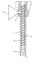
また、回転部材20は、一本の回転軸20aに複数の回転部材エレメントを軸方向に一体に回転可能に結合して構成する。本実施の形態では、矢印Aで示す投入物搬送方向の上流側から下流側に向けて、外径の小さい螺旋突条21aを有する回転部材エレメント22aと、螺旋突条21aと同じピッチで外径の大きい螺旋突条21bを有する回転部材エレメント22bと、螺旋突条21bと同じ外径でピッチの小さい螺旋突条21cを有する回転部材エレメント22cとを、回転軸20aに順次繰り返し結合して回転部材20を構成する。
【0048】
本実施の形態によると、外径の小さい螺旋突条21aを有する回転部材エレメント22aの部分では、投入物を攪拌しながら擦り合わせることができ、しかる後、螺旋突条21aと同じピッチで外径の大きい螺旋突条21bを有する回転部材エレメント22bの部分では、投入物同士を互いに加圧しながら擦り合わせることができ、更に螺旋突条21bと同じ外径でピッチの小さい螺旋突条21cを有する回転部材エレメント22cの部分では、投入物に作用する圧力を更に高めて、或いは投入物同士がなじみあい作用する圧力の低下を防止しながら擦り合わせることができ、しかもこれらの各作用を投入物の搬送に従って繰り返すことができるので、塗装樹脂製品の粗粉砕物50から塗膜をより効率良く除去することができる。
【0049】
(第4参考例)
図7及び図8は本発明に係る第4参考例の要部の構成を示すものである。本参考例は、第1実施の形態において回転部材20を、螺旋突条21dを有する回転部材エレメント22dと、螺旋突条とは異なる形状の突条を有する回転部材エレメント23とを、複数の回転部材エレメント22dの適宜の間に回転部材エレメント23が位置するように回転軸20aに配置して構成したものである。
【0050】
回転部材エレメント23は、図8にその斜視図を示すように、外形がほぼ楕円形状の複数の楕円状突条24を軸方向に平行で、かつ軸方向から見て、隣接する楕円状突条24の長軸方向が交差、本参考例では直交するように形成して構成されている。
【0051】
このように構成すると、螺旋突条21dを有する回転部材エレメント22dの部分では投入物同士を加圧しながら擦り合わせることができ、複数の楕円状突条24を有する回転部材エレメント23の部分では減圧によって投入物を攪拌しながら擦り合わせることができるので、塗装樹脂製品の粗粉砕物50から塗膜をより効率良く除去することができる。
【0052】
(第2実施の形態)
図9は本発明の第2実施の形態の要部の構成を示すものである。本実施の形態は、シリンダ部10を軸方向に着脱自在に連結した複数のシリンダエレメント11aをもって構成すると共に、回転部材20を異なる形態の螺旋突条を有する複数の回転部材エレメントと、異なる形態の楕円状突条を有する複数の回転部材エレメントと組み合わせて構成したものである。
【0053】
ここで、回転部材20は、矢印Aで示す投入物搬送方向の上流側から下流側に向けて、幅及び短軸長さの小さい複数の楕円状突条24aを有する回転部材エレメント23aと、この回転部材エレメント23aよりも幅及び短軸長さの大きい複数の楕円状突条24bを有する回転部材エレメント23bと、幅及びピッチの小さい螺旋突条21eを有する回転部材エレメント22eと、この回転部材エレメント22eよりも幅及びピッチの大きい螺旋突条21fを有する回転部材エレメント22fとを、その順序で回転軸20aに順次繰り返し結合して構成されている。
【0054】
従って、本実施の形態によると、回転部材エレメント23a及び23bの部分では、投入物が異なる圧力下で攪拌されながら擦り合わされ、回転部材エレメント22e及び22fの部分では、投入物同士が異なる加圧下で擦り合わされ、それらの作用が投入物の搬送に従って繰り返されるので、塗装樹脂製品の粗粉砕物50から塗膜をより効率良く除去することができる。
【0055】
(第3実施の形態)
図10は本発明の第3実施の形態の要部の構成を示すものである。本実施の形態は、第2実施の形態において、回転部材20を2種類の楕円状突条を有する回転部材エレメント、即ち、幅及び短軸長さの小さい複数の楕円状突条24aを有する回転部材エレメント23aと、この回転部材エレメント23aよりも幅及び短軸長さの大きい複数の楕円状突条24bを有する回転部材エレメント23bとを、矢印Aで示す投入物搬送方向の上流側から下流側に向けて回転軸20aに順次繰り返し結合して構成したものである。
【0056】
この場合も、投入物は回転部材エレメント23a及び23bの部分で異なる圧力下で攪拌されながら擦り合わされて矢印A方向に搬送されるので、塗装樹脂製品の粗粉砕物50から塗膜を効率良く除去することができる。
【0057】
(第5参考例)
図11は本発明に係る第5参考例の要部の構成を示す斜視図である。本参考例では、図1においてシリンダ部10を軸方向に着脱自在に連結した複数のシリンダエレメント11bをもって構成すると共に、各シリンダエレメント11bに互いに一部を重ね合わせて平行に第1のシリンダ15及び第2のシリンダ16を形成する。
【0058】
また、回転部材20は、第1のシリンダ15及び第2のシリンダ16内に各々第1の回転部材25及び第2の回転部材26を回転可能に挿通して構成し、これらを駆動部30により同一方向に回転駆動させる。なお、第1の回転部材25及び第2の回転部材26には、螺旋突条や楕円状突条を設ける。
【0059】
本参考例によると、第1のシリンダ15内及び第2のシリンダ16内で各々塗膜の剥離処理が行われるので処理能力をより高めることができると共に、投入物は第1のシリンダ15と第2のシリンダ16との間を移動し、攪拌されながら擦り合わされるので、塗膜をより効率良く除去することができる。
【0060】
本発明は上記実施の形態に限定されることなく、発明の趣旨を逸脱しない範囲で種々変更可能である。例えば、回転部材に螺旋突条を設ける場合には、螺旋突条は一条に限らず複数条設けることも可能である。また、回転部材に複数の楕円状突条を設ける場合には、順次の楕円状突条の長軸方向は90°に限らず、任意の角度例えば60°ずつ異なるように設けることもできる。更に、回転部材の突条は、大きさ、幅等が同じ複数の楕円状突条のみとすることもできる。更に、異なる螺旋突条を有する回転部材エレメントの組み合わせや、異なる楕円状突条を有する回転部材エレメントの組み合わせ、更にはその両者の組み合わせも、上記実施の形態で説明した以外の種々の組み合わせが可能である。
【0061】
また、シリンダ内面を粗面に形成して、塗装樹脂製品の粗粉砕物がシリンダ内面と擦り合うことでも塗膜が剥離されるようにして、塗膜の除去効率及び処理能力をより向上することができる。
【0062】
また、塗装樹脂製品の塗膜の密着強度は温度依存性が大きいので、シリンダ部に加熱手段を設けてシリンダ内を例えば40℃〜80℃に加熱し、これにより塗膜の剥離効率を一層高めることもできる。
【0063】
また、シリンダの下面に開口部を形成すると共に、その開口部にメッシュを設けて粗粉砕物から剥離された粒状の塗膜片の一部を落下させるようにすることもできる。このようにすれば、シリンダ部の排出口から押し出される排出物に含まれる塗膜片が少なくなるので、排出物から樹脂製基材と塗膜とを分離・分別する作業がより容易にできるようになる。
【0064】
【発明の効果】
本発明の塗装樹脂製品の塗膜剥離装置によれば、有機塩等の薬品や溶剤を使用することなく、かつ排水処理等の2次処理を要することなく、塗装樹脂製品を粗粉砕し、その粗粉砕物シリンダと回転部材とによりを擦り合わせながら搬送することで、樹脂製基材から塗膜を剥離することが可能になり、塗膜の除去効率、環境安全性及び処理能力の向上がもたらされると共に、例えばシリンダ部、回転部材あるいは駆動部は、例えば既存の押し出し成形機の部品を利用して構成することができるので、簡単かつ安価にできる。
【図面の簡単な説明】
【図1】 本発明に係る第1参考例における塗装樹脂製品の塗膜剥離装置の全体の構成を一部切り欠いて示す図である。
【図2】 図1に示すシリンダ部及び回転部材の詳細な構成を示す断面図である。
【図3】 第1参考例の動作を説明するための図である。
【図4】 本発明に係る第2参考例の要部を説明するための図である。
【図5】 同じく、第3参考例の要部を説明するための図である。
【図6】 本発明の第1実施の形態の要部の構成を示す図である。
【図7】 本発明に係る第4参考例の要部の構成を示す図である。
【図8】 図7の部分斜視図である。
【図9】 本発明の第2実施の形態の要部の構成を示す図である。
【図10】 同じく、第3実施の形態の要部の構成を示す図である。
【図11】 本発明に係る第5参考例の要部の構成を示す斜視図である。
【図12】 従来の剥離装置の概要を示す正面図である。
【図13】 図12のI−I線断面図である。
【図14】 樹脂製バンパの要部断面図である。
【符号の説明】
1 塗膜剥離装置
10 シリンダ部
11 シリンダ
11a、11b シリンダエレメント
12 投入口
13 排出口
15 第1のシリンダ
16 第2のシリンダ
20 回転部材
20a 回転軸
21、21a、21b、21c、21d、21e、21f 螺旋突条
22a、22b、22c、22d、22e、22f 回転部材エレメント
23、23a、23b 回転部材エレメント
24、24a、24b 楕円状突条
25 第1の回転部材
26 第2の回転部材
30 駆動部
40 ホッパ
50 粗粉砕物[0001]
BACKGROUND OF THE INVENTION
The present invention provides a coating film peeling of a coating resin product that peels a coating film from a coating resin product having a coating film on the surface of a resin substrate.Take offRelated to the position.
[0002]
[Prior art]
Recently, recycling of resin products has been screamed due to environmental issues and demands for resource reuse. For example, in the automotive industry, it is separated and recovered from in-process defective products and scrap cars generated when manufacturing resin products such as bumpers and side moldings. Recycling of plastic products is attracting attention.
[0003]
A resin product such as a bumper is often coated on the surface of the product in order to improve the appearance and quality. For example, in a resin bumper, the resin
[0004]
The
[0005]
The
[0006]
However, when this bumper is crushed and pelletized to obtain a recycled material, the polypropylene resin material constituting the
[0007]
For this reason, when recycling a resin product that has been coated, it is necessary to remove the coating film.
[0008]
This coating film removal method is mainly classified into mechanical, physical and chemical methods. The mechanical coating film removal method is, for example, a shot blasting method in which compressed air is sprayed onto the surface of a coating film formed on a resin product to destroy and remove the coating film or deposits. There is a screen mesh method or the like in which, after finely pulverizing a resin product, it is filtered through a screen mesh under heating and melting to remove a coating film piece mixed without melting.
[0009]
The shot brass method is excellent in toxicity and environmental safety because it removes the coating film by friction and impact, etc., but it requires a lot of processing time, the coating film removal efficiency is not enough, especially the processing of the curved part is difficult It is. In addition, the screen mesh method is excellent in toxicity and environmental safety because the coating piece is removed by filtration. However, when the screen mesh is clogged, the extrusion pressure is remarkably increased and the amount of extrusion is reduced to reduce the productivity. In addition, the removal efficiency of the coating film pieces is not sufficient, and it is necessary to replace the screen mesh in order to avoid a decrease in production efficiency due to clogging of the screen mesh.
[0010]
The physical coating removal method uses a halogen-based solvent or various organic solvents to remove the coating by utilizing the solvent penetration into the interface between the coating and the substrate and the swelling phenomenon of the coating by the solvent. In addition, it is inferior in environmental safety such as treatment of waste liquid, is relatively low in coating film removal efficiency and treatment capacity, and may further deteriorate the base material.
[0011]
Since these mechanical and physical coating film removal methods have low coating film removal efficiency, resin products using recycled resin materials obtained by these methods have a high production cost and a large application range. Limited.
[0012]
As the chemical coating film removal method, for example, there is an organic salt method in which a coating film is chemically decomposed and removed by cutting an ether bond in the vicinity of the crosslinking of a coating film resin with an ethanol water mixed solution containing an organic salt.
[0013]
This method has problems in secondary treatment such as wastewater treatment, has a low treatment capacity, and is not preferable in terms of treatment efficiency.
[0014]
Further, as disclosed in JP-A-5-337941, a synthetic resin surface peeling apparatus has been proposed in which a coating and a frictional force are applied to a coating film between a pair of rotating bodies to cut and peel the coating film. .
[0015]
As shown in the front view schematically shown in FIG. 12 and the cross-sectional view taken along the line I-I in FIG. 12, this peeling apparatus uses a pair of
[0016]
In this apparatus, since the resin products are brought into contact with the
[0017]
[Problems to be solved by the invention]
Therefore, the present invention made in view of such pointsEyesIn general, it is excellent in coating removal efficiency, environmental safety, and processing capacity, and enables the removal of coating film on coated resin products that makes it possible to obtain high-quality recycled resin products.apparatusIs to provide.
[0018]
[Means for Solving the Problems]
UpNoteThe coating film peeling of the coating resin product according to claim 1 which achieves the targetapparatusThe invention ofIn a coating resin peeling apparatus for coating resin products that peels a coating film from a coarsely pulverized coating resin product having a coating film on the surface of the resin substrate, an inlet is provided at one end and an outlet is provided at the other end. A cylinder part, a rotating member that is rotatably inserted into the cylinder of the cylinder part and has a protrusion on the outer periphery, and a drive part that rotationally drives the rotating member. The coarsely pulverized product of the coated resin product or the coarsely pulverized product and a polished product are mixed and charged, and the charged product is conveyed through the cylinder while being rubbed by the rotation of the rotating member. A first rotating member element configured to peel a coating film from a resin base material, wherein the rotating member has a spiral protrusion having a small outer diameter from the upstream side to the downstream side in the conveying direction of the input material. And a screw of the first rotating member element A second rotation member element having a spiral protrusion having a large outer diameter at the same pitch as the protrusion, and a third rotation having a spiral protrusion having the same outer diameter and a small pitch as the spiral protrusion of the second rotation member element The member element is configured by being sequentially and repeatedly coupled to the rotating shaft.
[0019]
According to the first aspect of the present invention, the coated resin product is coarsely pulverized without using chemicals or solvents such as organic salts and without requiring secondary treatment such as waste water treatment.Can be rubbed together while stirring at the portion of the first rotating member element having a spiral ridge having a small outer diameter, and thereafter, having a spiral ridge having a large outer diameter at the same pitch as the spiral ridge. In the second rotating member element portion, the charged materials can be rubbed against each other while being pressed against each other, and the third rotating member element has a spiral protrusion having the same outer diameter and small pitch as the spiral protrusion of the second rotating member element. In the rotating member element, the pressure acting on the input can be further increased, or the pressure can be rubbed against each other while preventing the decrease in the pressure that the input works well together. To repeat according toTherefore, it is possible to improve the removal efficiency of the coating film, environmental safety and processing ability.
[0020]
Claim 2The invention of the coating resin peeling apparatus for coated resin products is a coating film peeling apparatus for coating resin products that peels a coating film from a coarsely pulverized coating resin product having a coating film on the surface of a resin substrate. A cylinder portion having a discharge port on the other end side, a rotary member that is rotatably inserted into the cylinder of the cylinder portion and has a protrusion on the outer periphery, and a drive unit that rotationally drives the rotary member; The coarsely pulverized product of the coated resin product or the coarsely pulverized product and a polished product are mixed and charged into the cylinder from the charging port, and the charged product is rubbed by rotation of the rotating member. By transporting the inside of the cylinder, the coating film is peeled off from the resin base material of the coarsely pulverized product, and the rotating member has a width and a short width from the upstream side to the downstream side in the transport direction of the input material. 1st which has several elliptical protrusions with small axial length A rotating member element, a second rotating member element having a plurality of elliptical protrusions having a width and a short axis length larger than those of the first rotating member element, and a third member having a spiral protrusion having a small width and pitch. And a fourth rotating member element having a spiral protrusion having a width and a pitch larger than those of the third rotating member element, and sequentially coupled to the rotating shaft in that order. To do.
[0021]
According to the invention of claim 2,Without using chemicals such as organic salts or solvents, and without requiring secondary treatment such as wastewater treatment, the input material obtained by roughly pulverizing the coated resin product is used for the first rotating member element and the second rotating member element. The parts are rubbed together while being stirred under different pressures, and the charged parts are rubbed under different pressures in the third rotating member element and the fourth rotating element part, and each of these actions is repeated according to the conveyance of the charged substance. The removal efficiency of the coating film, environmental safety and processing capacityIt becomes possible to raise.
[0022]
ContractThe invention of a coating resin product coating film peeling apparatus according to claim 3 is a coating resin product coating film peeling apparatus for peeling a coating film from a coarsely pulverized product of a coating resin product having a coating film on the surface of a resin substrate. A cylinder portion having an inlet on one end side and a discharge port on the other end side, a rotating member rotatably inserted into the cylinder of the cylinder portion and having a protrusion on the outer periphery, and the rotating member. A drive unit that rotates, and the coarsely pulverized product of the coating resin product or the coarsely pulverized product and the polished product are mixed and fed into the cylinder from the charging port, and the charged product is fed to the rotating member. By conveying the inside of the cylinder while rubbing by rotation, it is configured to peel the coating film from the resin substrate of the coarsely pulverized product,The rotating member includes a first rotating member element having a plurality of elliptical protrusions having a small width and a short axis length, and a plurality of elliptical shapes having a width and a short axis length larger than those of the first rotating member element. A second rotating member element having a protrusion is configured by sequentially and repeatedly connecting to the rotating shaft from the upstream side to the downstream side in the conveying direction of the input material.It is characterized by that.
[0023]
According to the invention of claim 3,Without using chemicals or solvents such as organic salts and without requiring secondary treatment such as wastewater treatment, the input material obtained by roughly pulverizing the coated resin product is the parts of the first rotating member element and the second rotating element. In this case, they are rubbed together while being stirred under different pressures and conveyed from the upstream side to the downstream side, and these actions are repeated according to the conveyance of the input material, so that the removal efficiency of the coating film, the environmental safety and the processing capacity can be improved. Possible.
[0024]
Claim4The invention described in claimAny one of 1-3The coating film peeling apparatus for a coated resin product has a heating means for heating the inside of the cylinder.
[0025]
Claim4According to the invention, since the charged material is heated in the cylinder, it is possible to further improve the peeling efficiency of the coating film.
[0026]
Claim5The invention described in claimAny one of 1-4In the coating resin peeling apparatus for coating resin products, the cylinder has an opening formed on the lower surface of the cylinder and a mesh for dropping a part of the coating film peeled off from the coarsely pulverized material into the opening. It is provided.
[0027]
Claim5According to the invention, since a part of the coating film peeled off in the cylinder falls from the mesh, the work of separating and separating the resinous base material and the coating film from the discharge pushed out from the discharge port of the cylinder portion is performed. It becomes easy.
[0028]
Claim6The invention described in claim is a claim.Any one of 1-5In the paint resin film peeling apparatus, the cylinder part is constituted by a plurality of cylinder elements detachably connected in the axial direction.
[0029]
Claim6According to the invention, when a plurality of rotary elements are combined and arranged in the axial direction, the assembly can be easily performed, and when the lower surface of the cylinder is processed as in the invention of claim 5, Work can be easily performed.
[0030]
Claim7The invention described in claimAny one of 1-6In the coating film peeling apparatus for coated resin products, the inner surface of the cylinder is formed into a rough surface.
[0031]
Claim7According to the invention, the coarsely pulverized product of the coated resin product is peeled off even by rubbing against the inner surface of the cylinder, so that the removal efficiency and processing ability of the coating film can be further improved.
[0032]
DETAILED DESCRIPTION OF THE INVENTION
Hereinafter, coating film peeling of the coated resin product according to the present inventionReference examples related to equipment andEmbodiments will be described with reference to the drawings.
[0033]
(First reference example)
1 through 3First reference exampleWill be explained. FIG. 1 is a partially cutaway view showing the entire structure, FIG. 2 is a cross-sectional view showing a detailed structure of a cylinder part and a rotating member, and FIG. 3 is a view for explaining the operation.
[0034]
As shown in FIG. 1, the coating film peeling apparatus 1 includes a
[0035]
As shown in FIG. 2, the
[0036]
BookReference exampleThen, a coating resin product having a coating film to be peeled off, such as a bumper, is coarsely pulverized in advance, and the coarsely pulverized product 50 is directly in the
[0037]
As described above, when the coarsely pulverized product 50 of the coating resin product is put into the
[0038]
At that time, the coarsely pulverized product is rubbed against each other by the rotational force of the rotating
[0039]
Here, the coating film of the coarsely pulverized product 50 is peeled off in a granular manner in the
[0040]
Moreover, since the
[0041]
Moreover, the coating resin product is roughly pulverized without using chemicals such as organic salts and solvents, and without requiring secondary treatment such as wastewater treatment, and the coarsely pulverized product 50 is rubbed by the
[0042]
(Second reference example)
The present inventionIn the second reference example concerning the first reference exampleIn FIG. 4, the
[0043]
With this configuration, the pitch of the
[0044]
(Third reference example)
The present inventionIn the third reference example concerning the first reference example5 is characterized in that the
[0045]
Also in this case, the gap between the
[0046]
(No.1Embodiment)
FIG.1The structure of the principal part of embodiment is shown. The present embodiment is characterized in that, in the configuration shown in FIG. 1, the
[0047]
The rotating
[0048]
According to the present embodiment, in the portion of the rotating
[0049]
(Fourth reference example)
7 and 8 relate to the present invention.Fourth reference exampleThe structure of the principal part of is shown. BookReference exampleThe second1In the embodiment, the rotating
[0050]
As shown in the perspective view of FIG. 8, the rotating
[0051]
If comprised in this way, in the part of the rotating
[0052]
(No.2Embodiment)
FIG. 9 shows the first aspect of the present invention.2The structure of the principal part of embodiment is shown. The present embodiment is configured with a plurality of
[0053]
Here, the rotating
[0054]
Therefore, according to the present embodiment, the parts of the rotating
[0055]
(No.3Embodiment)
FIG. 10 shows the first aspect of the present invention.3The structure of the principal part of embodiment is shown. This embodiment is the first2In the embodiment, the rotating
[0056]
Also in this case, the input material is rubbed while being stirred at different pressures at the rotating
[0057]
(5th reference example)
FIG. 11 relates to the present invention.5th reference exampleIt is a perspective view which shows the structure of the principal part. In this reference example, in FIG. 1, the
[0058]
The rotating
[0059]
According to this reference example, the coating film is peeled off in each of the
[0060]
The present invention is not limited to the above-described embodiment, and various modifications can be made without departing from the spirit of the invention. For example, when a spiral protrusion is provided on the rotating member, the spiral protrusion is not limited to a single line, and a plurality of lines can be provided. Further, when a plurality of elliptical ridges are provided on the rotating member, the major axis direction of the sequential elliptical ridges is not limited to 90 °, but can be provided so as to be different by an arbitrary angle, for example, 60 °. Furthermore, the protrusions of the rotating member may be only a plurality of elliptical protrusions having the same size, width and the like. Furthermore, a combination of rotating member elements having different spiral ridges, a combination of rotating member elements having different elliptical ridges, and a combination of both may be various combinations other than those described in the above embodiment. It is.
[0061]
In addition, the inner surface of the cylinder is formed into a rough surface so that the coating film is peeled off even when the coarsely pulverized product of the coated resin product rubs against the inner surface of the cylinder, thereby improving the coating film removal efficiency and processing capacity. Can do.
[0062]
In addition, since the adhesion strength of the coating film of the coated resin product is highly temperature dependent, a heating means is provided in the cylinder portion to heat the inside of the cylinder to, for example, 40 ° C. to 80 ° C., thereby further improving the peeling efficiency of the coating film. You can also.
[0063]
Moreover, while forming an opening part in the lower surface of a cylinder, a mesh can be provided in the opening part, and a part of granular coating-film piece peeled from the coarsely pulverized material can also be dropped. In this way, since the amount of the coating film contained in the discharge pushed out from the discharge port of the cylinder part is reduced, the work of separating and separating the resin base material and the coating film from the discharge can be made easier. become.
[0064]
【The invention's effect】
According to the coating film peeling apparatus for a coated resin product of the present invention, the coated resin product is roughly pulverized without using chemicals or solvents such as organic salts and without requiring secondary treatment such as waste water treatment. By transporting the coarsely pulverized product cylinder and the rotating member while rubbing them together, it becomes possible to peel the coating film from the resin base material, resulting in improved coating film removal efficiency, environmental safety and processing capacity. In addition, for example, the cylinder portion, the rotating member, or the drive portion can be configured by using, for example, parts of an existing extrusion molding machine, so that it can be made simple and inexpensive.
[Brief description of the drawings]
FIG. 1 shows the present invention.First reference exampleIt is a figure which notches and shows a part of whole structure of the coating-film peeling apparatus of the coating resin product in FIG.
FIG. 2 is a cross-sectional view showing a detailed configuration of a cylinder portion and a rotating member shown in FIG.
FIG. 3Reference exampleIt is a figure for demonstrating operation | movement of.
FIG. 4 The present inventionSecond reference example related toIt is a figure for demonstrating the principal part of.
FIG. 5 is also a diagram for explaining a main part of a third reference example.
[Fig. 6]Of the present inventionFirst1It is a figure which shows the structure of the principal part of embodiment.
[Fig. 7]Fourth reference example according to the present inventionIt is a figure which shows the structure of the principal part.
8 is a partial perspective view of FIG. 7. FIG.
FIG. 9 shows the first of the present invention.2It is a figure which shows the structure of the principal part of embodiment.
[Fig. 10] Similarly,3It is a figure which shows the structure of the principal part of embodiment.
FIG. 11Fifth reference example according to the present inventionIt is a perspective view which shows the structure of the principal part.
FIG. 12 is a front view showing an outline of a conventional peeling apparatus.
13 is a cross-sectional view taken along the line II of FIG.
FIG. 14 is a cross-sectional view of a main part of a resin bumper.
[Explanation of symbols]
1 Coating film peeling device
10 Cylinder part
11 cylinders
11a, 11b Cylinder element
12 slot
13 Discharge port
15 First cylinder
16 Second cylinder
20 Rotating member
20a Rotating shaft
21, 21a, 21b, 21c, 21d, 21e, 21f Spiral ridge
22a, 22b, 22c, 22d, 22e, 22f Rotating member element
23, 23a, 23b Rotating member element
24, 24a, 24b Elliptical ridge
25 First rotating member
26 Second rotating member
30 Drive unit
40 hoppers
50 Coarse pulverized product
Claims (7)
一端部側に投入口を、他端部側に排出口を有するシリンダ部と、
該シリンダ部のシリンダ内に回転可能に挿通され、外周に突条を有する回転部材と、
該回転部材を回転駆動する駆動部とを有し、
上記投入口から上記シリンダ内に上記塗装樹脂製品の粗粉砕物または該粗粉砕物と研磨物とを混合して投入し、該投入物を上記回転部材の回転により擦り合わせながら上記シリンダ内を搬送することにより、粗粉砕物の樹脂製基材から塗膜を剥離するよう構成し、
上記回転部材は、上記投入物の搬送方向の上流側から下流側に向けて、外径の小さい螺旋突条を有する第1の回転部材エレメントと、該第1の回転部材エレメントの螺旋突条と同じピッチで外径の大きい螺旋突条を有する第2の回転部材エレメントと、第2の回転部材エレメントの螺旋突条と同じ外径でピッチの小さい螺旋突条を有する第3の回転部材エレメントとを、回転軸に順次繰り返し結合して構成する
ことを特徴とする塗装樹脂製品の塗膜剥離装置。In the coating film peeling apparatus for coating resin products that peels the coating film from the coarsely pulverized product of the coating resin product having a coating film on the surface of the resin substrate,
A cylinder part having an inlet on one end side and an outlet on the other end side;
A rotating member rotatably inserted into the cylinder of the cylinder portion and having a protrusion on the outer periphery;
A drive unit that rotationally drives the rotating member;
The coated resin product coarsely pulverized product or the coarsely pulverized product and a polished product are mixed and fed into the cylinder from the charging port, and the charged product is conveyed through the cylinder while being rubbed by rotation of the rotating member. By doing so, it is configured to peel the coating film from the resin substrate of the coarsely pulverized product,
The rotating member includes a first rotating member element having a helical protrusion having a small outer diameter from the upstream side to the downstream side in the conveying direction of the input material, and the helical protrusion of the first rotating member element. A second rotating member element having a spiral protrusion having a large outer diameter at the same pitch, and a third rotating member element having a spiral protrusion having a small outer pitch and the same outer diameter as the spiral protrusion of the second rotating member element; A coating film peeling apparatus for a coated resin product, wherein the coating film is repeatedly and sequentially coupled to a rotating shaft .
一端部側に投入口を、他端部側に排出口を有するシリンダ部と、
該シリンダ部のシリンダ内に回転可能に挿通され、外周に突条を有する回転部材と、
該回転部材を回転駆動する駆動部とを有し、
上記投入口から上記シリンダ内に上記塗装樹脂製品の粗粉砕物または該粗粉砕物と研磨物とを混合して投入し、該投入物を上記回転部材の回転により擦り合わせながら上記シリンダ内を搬送することにより、粗粉砕物の樹脂製基材から塗膜を剥離するよう構成し、
上記回転部材は、上記投入物の搬送方向の上流側から下流側に向けて、幅及び短軸長さの小さい複数の楕円状突条を有する第1の回転部材エレメントと、該第1の回転部材エレメントよりも幅及び短軸長さの大きい複数の楕円状突条を有する第2の回転部材エレメントと、幅及びピッチの小さい螺旋突条を有する第3の回転部材エレメントと、第3の回転部材エレメントよりも幅及びピッチの大きい螺旋突条を有する第4の回転部材エレメントとを、その順序で回転軸に順次繰り返し結合して構成する
ことを特徴とする塗装樹脂製品の塗膜剥離装置。In the coating film peeling apparatus for coating resin products that peels the coating film from the coarsely pulverized product of the coating resin product having a coating film on the surface of the resin substrate,
A cylinder part having an inlet on one end side and an outlet on the other end side;
A rotating member rotatably inserted into the cylinder of the cylinder portion and having a protrusion on the outer periphery;
A drive unit that rotationally drives the rotating member;
The coated resin product coarsely pulverized product or the coarsely pulverized product and a polished product are mixed and fed into the cylinder from the charging port, and the charged product is conveyed through the cylinder while being rubbed by rotation of the rotating member. By doing so, it is configured to peel the coating film from the resin substrate of the coarsely pulverized product,
The rotating member includes a first rotating member element having a plurality of elliptical protrusions having a small width and short axis length from the upstream side to the downstream side in the conveying direction of the input material, and the first rotation. A second rotating member element having a plurality of elliptical ridges having a larger width and minor axis length than the member element, a third rotating member element having a helical ridge having a smaller width and pitch, and a third rotation A coating resin product characterized by comprising a fourth rotating member element having a spiral protrusion having a width and pitch larger than that of the member element and sequentially connecting to the rotating shaft in that order. Membrane peeling device.
一端部側に投入口を、他端部側に排出口を有するシリンダ部と、
該シリンダ部のシリンダ内に回転可能に挿通され、外周に突条を有する回転部材と、
該回転部材を回転駆動する駆動部とを有し、
上記投入口から上記シリンダ内に上記塗装樹脂製品の粗粉砕物または該粗粉砕物と研磨物とを混合して投入し、該投入物を上記回転部材の回転により擦り合わせながら上記シリンダ内を搬送することにより、粗粉砕物の樹脂製基材から塗膜を剥離するよう構成し、
上記回転部材を、幅及び短軸長さの小さい複数の楕円状突条を有する第1の回転部材エレメントと、該第1の回転部材エレメントよりも幅及び短軸長さの大きい複数の楕円状突条を有する第2の回転部材エレメントとを、上記投入物の搬送方向の上流側から下流側に向けて回転軸に順次順次繰り返し結合して構成する
ことを特徴とする塗装樹脂製品の塗膜剥離装置。In the coating film peeling apparatus for coating resin products that peels the coating film from the coarsely pulverized product of the coating resin product having a coating film on the surface of the resin substrate,
A cylinder part having an inlet on one end side and an outlet on the other end side;
A rotating member rotatably inserted into the cylinder of the cylinder portion and having a protrusion on the outer periphery;
A drive unit that rotationally drives the rotating member;
The coated resin product coarsely pulverized product or the coarsely pulverized product and a polished product are mixed and fed into the cylinder from the charging port, and the charged product is conveyed through the cylinder while being rubbed by rotation of the rotating member. By doing so, it is configured to peel the coating film from the resin substrate of the coarsely pulverized product,
The rotating member includes a first rotating member element having a plurality of elliptical protrusions having a small width and a short axis length, and a plurality of elliptical shapes having a width and a short axis length larger than those of the first rotating member element. A coating resin, comprising: a second rotating member element having a ridge, which is sequentially and repeatedly coupled to a rotating shaft from the upstream side to the downstream side in the conveying direction of the input material. Product film peeling equipment.
該シリンダの下面に開口部を形成すると共に、該開口部に上記粗粉砕物から剥離された塗膜片の一部を落下させるメッシュを設けたことを特徴とする請求項1〜4のいずれか1項に記載の塗装樹脂製品の塗膜剥離装置。The cylinder is
The opening according to any one of claims 1 to 4, wherein an opening is formed on the lower surface of the cylinder, and a mesh is provided in the opening to drop a part of the coating film piece peeled off from the coarsely pulverized material . The coating film peeling apparatus of the coating resin product of 1 item | term .
軸方向に着脱自在に連結した複数のシリンダエレメントをもって構成したことを特徴とする請求項1〜5のいずれか1項に記載の塗装樹脂製品の塗膜剥離装置。The cylinder part is
The coating resin peeling apparatus for a coated resin product according to any one of claims 1 to 5, comprising a plurality of cylinder elements that are detachably connected in an axial direction.
Priority Applications (5)
| Application Number | Priority Date | Filing Date | Title |
|---|---|---|---|
| JP2000009520A JP4226745B2 (en) | 2000-01-18 | 2000-01-18 | Coating film peeling equipment for painted resin products |
| DE2001633235 DE60133235T2 (en) | 2000-01-18 | 2001-01-03 | Method and device for removing a coating of a plastic product |
| EP20010100268 EP1122048B1 (en) | 2000-01-18 | 2001-01-03 | Method and apparatus for peeling a coating film of a coated resin product |
| US09/754,110 US6672523B2 (en) | 2000-01-18 | 2001-01-05 | Method and apparatus for peeling a coating film of a coated resin product |
| US10/217,952 US6702211B2 (en) | 2000-01-18 | 2002-08-12 | Method and apparatus for peeling a coating film of a coated resin product |
Applications Claiming Priority (1)
| Application Number | Priority Date | Filing Date | Title |
|---|---|---|---|
| JP2000009520A JP4226745B2 (en) | 2000-01-18 | 2000-01-18 | Coating film peeling equipment for painted resin products |
Publications (2)
| Publication Number | Publication Date |
|---|---|
| JP2001198919A JP2001198919A (en) | 2001-07-24 |
| JP4226745B2 true JP4226745B2 (en) | 2009-02-18 |
Family
ID=18537662
Family Applications (1)
| Application Number | Title | Priority Date | Filing Date |
|---|---|---|---|
| JP2000009520A Expired - Fee Related JP4226745B2 (en) | 2000-01-18 | 2000-01-18 | Coating film peeling equipment for painted resin products |
Country Status (4)
| Country | Link |
|---|---|
| US (2) | US6672523B2 (en) |
| EP (1) | EP1122048B1 (en) |
| JP (1) | JP4226745B2 (en) |
| DE (1) | DE60133235T2 (en) |
Families Citing this family (8)
| Publication number | Priority date | Publication date | Assignee | Title |
|---|---|---|---|---|
| JP2003178642A (en) * | 2001-12-11 | 2003-06-27 | Polymatech Co Ltd | Key pad and method for separating its cross-linking curable resin layer |
| JP4594797B2 (en) * | 2005-05-27 | 2010-12-08 | 富士重工業株式会社 | Resin product surface material peeling device |
| JP2007229930A (en) * | 2006-02-27 | 2007-09-13 | Daizen:Kk | Color peeling method |
| CA2701277A1 (en) * | 2007-10-03 | 2009-04-09 | Lawrence Pumps Inc. | Inducer comminutor |
| KR101229655B1 (en) * | 2007-12-31 | 2013-02-04 | 코웨이 주식회사 | A Drier of Food Treatment System |
| US7841498B1 (en) | 2008-01-04 | 2010-11-30 | Rohrer Neal D | Tape dispenser from a single stamping operation |
| JP5875479B2 (en) * | 2012-07-24 | 2016-03-02 | 山崎 純生 | Plastic waste extrusion equipment |
| CN106079839B (en) * | 2016-06-23 | 2018-03-06 | 捷星显示科技(福建)有限公司 | Automatic dyestripping machine |
Family Cites Families (17)
| Publication number | Priority date | Publication date | Assignee | Title |
|---|---|---|---|---|
| GB779364A (en) * | 1954-09-30 | 1957-07-17 | Welding Engineers | Treatment of plastic materials |
| GB865933A (en) * | 1958-08-23 | 1961-04-26 | Bayer Ag | A mixing worm |
| NL128227C (en) * | 1963-09-20 | 1900-01-01 | ||
| US3749322A (en) * | 1972-04-03 | 1973-07-31 | Entoleter | Method of impact milling and aspirating scrap insulated wire to recover metal valves |
| DE3690220T1 (en) * | 1985-05-02 | 1987-06-04 | ||
| US5567245A (en) * | 1991-02-14 | 1996-10-22 | Watson; Dana L. | Method for separating vinylidene chloride polymer from other polymers |
| JPH05237410A (en) | 1992-02-27 | 1993-09-17 | Yamashiyou:Kk | Treatment of bamper of car |
| DE4217005C2 (en) * | 1992-05-22 | 1994-03-03 | Himont Inc | Process for recovering plastic from painted plastic parts |
| JP3116554B2 (en) | 1992-06-04 | 2000-12-11 | トヨタ自動車株式会社 | Synthetic resin surface peeling device |
| JP3117808B2 (en) * | 1992-09-25 | 2000-12-18 | 日産自動車株式会社 | Coating removal method |
| US5566888A (en) * | 1993-05-21 | 1996-10-22 | Fuji Jukogyo Kabushiki Kaisha | Method and an apparatus for recycling a resin component |
| JPH07156149A (en) * | 1993-12-10 | 1995-06-20 | Japan Steel Works Ltd:The | Separation of coating film of plastic product having coating film and method and apparatus for regeneration treatment of plastic product |
| JP2829236B2 (en) | 1994-03-22 | 1998-11-25 | 富士重工業株式会社 | How to recycle painted resin products |
| JPH07276364A (en) | 1994-04-15 | 1995-10-24 | Yakushin Kikai Seisakusho:Kk | Separation device of surface coating of resin waste matter |
| US5609256A (en) * | 1995-01-04 | 1997-03-11 | Carpco, Inc. | Process for recovery of values from solid waste materials |
| DE29723087U1 (en) * | 1996-02-10 | 1998-04-09 | Theysohn Friedrich Fa | Compounder for plasticizable materials |
| US6138929A (en) * | 1999-08-16 | 2000-10-31 | Montgomery; Michael | Process for removing paint from polymeric material |
-
2000
- 2000-01-18 JP JP2000009520A patent/JP4226745B2/en not_active Expired - Fee Related
-
2001
- 2001-01-03 DE DE2001633235 patent/DE60133235T2/en not_active Expired - Fee Related
- 2001-01-03 EP EP20010100268 patent/EP1122048B1/en not_active Expired - Lifetime
- 2001-01-05 US US09/754,110 patent/US6672523B2/en not_active Expired - Fee Related
-
2002
- 2002-08-12 US US10/217,952 patent/US6702211B2/en not_active Expired - Fee Related
Also Published As
| Publication number | Publication date |
|---|---|
| DE60133235T2 (en) | 2009-04-30 |
| EP1122048A2 (en) | 2001-08-08 |
| EP1122048A3 (en) | 2001-11-21 |
| JP2001198919A (en) | 2001-07-24 |
| EP1122048B1 (en) | 2008-03-19 |
| US20030015613A1 (en) | 2003-01-23 |
| US6702211B2 (en) | 2004-03-09 |
| DE60133235D1 (en) | 2008-04-30 |
| US20010008170A1 (en) | 2001-07-19 |
| US6672523B2 (en) | 2004-01-06 |
Similar Documents
| Publication | Publication Date | Title |
|---|---|---|
| JP4226745B2 (en) | Coating film peeling equipment for painted resin products | |
| US5788811A (en) | Method and apparatus for peeling coating from coated plastics and method for recycling plastics | |
| JP3177403B2 (en) | Equipment for removing and removing paint film from painted resin products | |
| JP3177371B2 (en) | How to recycle painted resin products | |
| JP3177401B2 (en) | Apparatus for removing paint film from painted resin products | |
| JP2003507164A (en) | Method of removing paint from polymer material | |
| JP4594797B2 (en) | Resin product surface material peeling device | |
| JP3177402B2 (en) | Paint film removal equipment for painted resin products | |
| KR102014072B1 (en) | Apparatus for Recycling Waste Powdery Paint | |
| JP2002321218A (en) | Method and apparatus for peeling surface material of resin product | |
| JP2829236B2 (en) | How to recycle painted resin products | |
| JP3177373B2 (en) | How to recycle painted resin products | |
| JP3177372B2 (en) | How to recycle painted resin products | |
| JP3177400B2 (en) | Paint film peeling method and paint film peeling device for painted resin products | |
| US5891296A (en) | Apparatus and method for peeling and removing a coated film on resin product | |
| JP3177416B2 (en) | Injection molding equipment for coating resin product recycling | |
| JP3177462B2 (en) | Conveyor for coating film removal equipment | |
| JP2004114512A (en) | Coating film removing apparatus | |
| JPH06328444A (en) | Recycling method and device for resin component | |
| JPH06143282A (en) | Sealed rotary feeder |
Legal Events
| Date | Code | Title | Description |
|---|---|---|---|
| A621 | Written request for application examination |
Free format text: JAPANESE INTERMEDIATE CODE: A621 Effective date: 20061207 |
|
| A977 | Report on retrieval |
Free format text: JAPANESE INTERMEDIATE CODE: A971007 Effective date: 20080811 |
|
| A131 | Notification of reasons for refusal |
Free format text: JAPANESE INTERMEDIATE CODE: A131 Effective date: 20080819 |
|
| A521 | Request for written amendment filed |
Free format text: JAPANESE INTERMEDIATE CODE: A523 Effective date: 20081020 |
|
| TRDD | Decision of grant or rejection written | ||
| A01 | Written decision to grant a patent or to grant a registration (utility model) |
Free format text: JAPANESE INTERMEDIATE CODE: A01 Effective date: 20081118 |
|
| A01 | Written decision to grant a patent or to grant a registration (utility model) |
Free format text: JAPANESE INTERMEDIATE CODE: A01 |
|
| A61 | First payment of annual fees (during grant procedure) |
Free format text: JAPANESE INTERMEDIATE CODE: A61 Effective date: 20081127 |
|
| FPAY | Renewal fee payment (event date is renewal date of database) |
Free format text: PAYMENT UNTIL: 20111205 Year of fee payment: 3 |
|
| R150 | Certificate of patent or registration of utility model |
Free format text: JAPANESE INTERMEDIATE CODE: R150 |
|
| FPAY | Renewal fee payment (event date is renewal date of database) |
Free format text: PAYMENT UNTIL: 20111205 Year of fee payment: 3 |
|
| FPAY | Renewal fee payment (event date is renewal date of database) |
Free format text: PAYMENT UNTIL: 20121205 Year of fee payment: 4 |
|
| FPAY | Renewal fee payment (event date is renewal date of database) |
Free format text: PAYMENT UNTIL: 20121205 Year of fee payment: 4 |
|
| FPAY | Renewal fee payment (event date is renewal date of database) |
Free format text: PAYMENT UNTIL: 20131205 Year of fee payment: 5 |
|
| R250 | Receipt of annual fees |
Free format text: JAPANESE INTERMEDIATE CODE: R250 |
|
| S531 | Written request for registration of change of domicile |
Free format text: JAPANESE INTERMEDIATE CODE: R313531 |
|
| R350 | Written notification of registration of transfer |
Free format text: JAPANESE INTERMEDIATE CODE: R350 |
|
| R250 | Receipt of annual fees |
Free format text: JAPANESE INTERMEDIATE CODE: R250 |
|
| LAPS | Cancellation because of no payment of annual fees |