JP4222663B2 - Modular supports for functional elements of high-voltage power supply units and the resulting units - Google Patents
Modular supports for functional elements of high-voltage power supply units and the resulting units Download PDFInfo
- Publication number
- JP4222663B2 JP4222663B2 JP28762098A JP28762098A JP4222663B2 JP 4222663 B2 JP4222663 B2 JP 4222663B2 JP 28762098 A JP28762098 A JP 28762098A JP 28762098 A JP28762098 A JP 28762098A JP 4222663 B2 JP4222663 B2 JP 4222663B2
- Authority
- JP
- Japan
- Prior art keywords
- module
- housing
- base
- protruding
- wall
- Prior art date
- Legal status (The legal status is an assumption and is not a legal conclusion. Google has not performed a legal analysis and makes no representation as to the accuracy of the status listed.)
- Expired - Fee Related
Links
- 230000000295 complement effect Effects 0.000 claims description 19
- 238000004804 winding Methods 0.000 claims description 13
- 239000002184 metal Substances 0.000 claims description 6
- 239000007788 liquid Substances 0.000 claims description 2
- 239000002991 molded plastic Substances 0.000 claims description 2
- 238000010292 electrical insulation Methods 0.000 description 5
- 238000004519 manufacturing process Methods 0.000 description 5
- 238000010894 electron beam technology Methods 0.000 description 4
- 230000007423 decrease Effects 0.000 description 2
- 230000005684 electric field Effects 0.000 description 2
- 238000009413 insulation Methods 0.000 description 2
- 238000000465 moulding Methods 0.000 description 2
- 239000004033 plastic Substances 0.000 description 2
- 239000000853 adhesive Substances 0.000 description 1
- 230000001070 adhesive effect Effects 0.000 description 1
- 239000003990 capacitor Substances 0.000 description 1
- 239000004020 conductor Substances 0.000 description 1
- 238000001816 cooling Methods 0.000 description 1
- 239000000110 cooling liquid Substances 0.000 description 1
- 238000010586 diagram Methods 0.000 description 1
- 239000003989 dielectric material Substances 0.000 description 1
- 239000012530 fluid Substances 0.000 description 1
- 238000009499 grossing Methods 0.000 description 1
- 230000037431 insertion Effects 0.000 description 1
- 238000003780 insertion Methods 0.000 description 1
- 239000011810 insulating material Substances 0.000 description 1
- WABPQHHGFIMREM-UHFFFAOYSA-N lead(0) Chemical compound [Pb] WABPQHHGFIMREM-UHFFFAOYSA-N 0.000 description 1
- 230000013011 mating Effects 0.000 description 1
- 230000005404 monopole Effects 0.000 description 1
- 230000005405 multipole Effects 0.000 description 1
- 230000009466 transformation Effects 0.000 description 1
Images
Classifications
-
- H—ELECTRICITY
- H05—ELECTRIC TECHNIQUES NOT OTHERWISE PROVIDED FOR
- H05K—PRINTED CIRCUITS; CASINGS OR CONSTRUCTIONAL DETAILS OF ELECTRIC APPARATUS; MANUFACTURE OF ASSEMBLAGES OF ELECTRICAL COMPONENTS
- H05K7/00—Constructional details common to different types of electric apparatus
- H05K7/14—Mounting supporting structure in casing or on frame or rack
- H05K7/1422—Printed circuit boards receptacles, e.g. stacked structures, electronic circuit modules or box like frames
- H05K7/1427—Housings
- H05K7/1432—Housings specially adapted for power drive units or power converters
-
- H—ELECTRICITY
- H02—GENERATION; CONVERSION OR DISTRIBUTION OF ELECTRIC POWER
- H02M—APPARATUS FOR CONVERSION BETWEEN AC AND AC, BETWEEN AC AND DC, OR BETWEEN DC AND DC, AND FOR USE WITH MAINS OR SIMILAR POWER SUPPLY SYSTEMS; CONVERSION OF DC OR AC INPUT POWER INTO SURGE OUTPUT POWER; CONTROL OR REGULATION THEREOF
- H02M7/00—Conversion of AC power input into DC power output; Conversion of DC power input into AC power output
- H02M7/02—Conversion of AC power input into DC power output without possibility of reversal
- H02M7/04—Conversion of AC power input into DC power output without possibility of reversal by static converters
- H02M7/06—Conversion of AC power input into DC power output without possibility of reversal by static converters using discharge tubes without control electrode or semiconductor devices without control electrode
- H02M7/10—Conversion of AC power input into DC power output without possibility of reversal by static converters using discharge tubes without control electrode or semiconductor devices without control electrode arranged for operation in series, e.g. for multiplication of voltage
- H02M7/103—Containing passive elements (capacitively coupled) which are ordered in cascade on one source
- H02M7/106—With physical arrangement details
-
- H—ELECTRICITY
- H05—ELECTRIC TECHNIQUES NOT OTHERWISE PROVIDED FOR
- H05G—X-RAY TECHNIQUE
- H05G1/00—X-ray apparatus involving X-ray tubes; Circuits therefor
- H05G1/02—Constructional details
- H05G1/04—Mounting the X-ray tube within a closed housing
- H05G1/06—X-ray tube and at least part of the power supply apparatus being mounted within the same housing
-
- H—ELECTRICITY
- H05—ELECTRIC TECHNIQUES NOT OTHERWISE PROVIDED FOR
- H05K—PRINTED CIRCUITS; CASINGS OR CONSTRUCTIONAL DETAILS OF ELECTRIC APPARATUS; MANUFACTURE OF ASSEMBLAGES OF ELECTRICAL COMPONENTS
- H05K7/00—Constructional details common to different types of electric apparatus
- H05K7/14—Mounting supporting structure in casing or on frame or rack
- H05K7/1422—Printed circuit boards receptacles, e.g. stacked structures, electronic circuit modules or box like frames
- H05K7/1427—Housings
- H05K7/1432—Housings specially adapted for power drive units or power converters
- H05K7/14339—Housings specially adapted for power drive units or power converters specially adapted for high voltage operation
Landscapes
- Engineering & Computer Science (AREA)
- Microelectronics & Electronic Packaging (AREA)
- Power Engineering (AREA)
- X-Ray Techniques (AREA)
- Casings For Electric Apparatus (AREA)
- Dc-Dc Converters (AREA)
Description
【0001】
【発明の属する技術分野】
本発明は、とくに高電圧電源機能構成部材のすべてを単一のボックス中に納めたX線管用の高電圧(HT)電源ユニットに関する。
【0002】
【従来の技術】
X線管は、陽極に向かって電子ビームを放射するフィラメント形式の陰極を含む。陽極は、電子ビームの作用を受けてX線ビームを放射する。高エネルギーの電子ビームを得るために、陰極から放射された電子ビームは、陰極と陽極の間に作られた強い電界によって加速される。これを達成するために、陽極を陰極に対して正電位に上げ、陽極と陰極の間の電位差は一般に150kVまたはそれ以上の値に達する。これらの極めて高い電位差は高電圧装置によって得られる。
これらの高電圧装置の機能エレメントは、電気絶縁と冷却を行う液体で満たした接地された金属製ボックス中に納められている。
【0003】
機能エレメントは通常、第1巻線、第2巻線、磁気コア、HT整流器、およびHT平滑コンデンサを含む、高変成比HT変圧器を含む。
さらに詳しくは、変圧器は、周波数変換装置によって供給される交流電圧が印加される1次巻線と、倍電圧整流回路に接続された2次巻線とを有する。各2次巻線の倍電圧整流回路は共に接続されているので、これらの電圧は組み合わされる。整流器の極性を考慮して、正電圧か負電圧を印加して、X線管に電力供給するために必要な高電圧レベルを得ることができる。
【0004】
HTユニット内の高電圧出力部は、HTボックス・カバー・プレートを通じて気密状態に密封されたHTコネクタに接続された抵抗器によって保護され、HTリード線のコネクタ・ピンを収容するソケットがHT装置をX線管に接続する。HT出力部もHTユニットの内部で電圧分割抵抗器に接続される。その電圧分割抵抗器は、出力される高電圧のレベルに比例する低電圧を供給する電圧分割器の上部を形成する。
ボックスの内部には、機能エレメント間の電気的接続を行うため、およびHT電源装置をX線管に電気的に接続するために必要な導線もある。
機能エレメントのすべては、ボックスの内部に支持され、電気的に互いに絶縁される必要がある。
【0005】
【発明が解決しようとする課題】
したがって本発明は、機能エレメントのための支持とこれらの電気的な絶縁との両方を行い、かつ最小数の部材を含み製造が容易で低コストである、HTユニットの機能エレメントのための支持物を提供することを課題とする。
【0006】
さらに詳細には、本発明は、高電圧電源ユニットのためのモジュール式支持物であって、高電圧電源ユニット中に高電圧電源のすべての機能構成部材が絶縁物質で作られたモジュール式支持物によって支持され、モジュール式支持物と機能構成部材とは共に、熱伝導を促進させる電気絶縁流体で満たされた単一の接地された金属ボックス中に配置されているモジュール式支持物を提供することを課題とする。
【0007】
本発明の別の主題は、HT変圧器の構成部材、倍電圧整流回路、電圧分割器の抵抗器ボックス、および出力保護抵抗器のすべてがまとめられている、上に述べたHTユニットの機能エレメント用の支持物を提供することである。
【0008】
本発明のさらに別の主題は、HT出力ソケット、フィラメント変圧器、そして場合によってはHT出力整流子をまとめたHT出力ユニットをも組み込んだ、上に述べた支持物を提供することである。
【0009】
【課題を解決するための手段】
上記の目的は、電気絶縁された壁を有し、HT電源ユニットの機能エレメントを収容するためのハウジングを含み、ハウジングの電気絶縁された壁は、重なった相補傾斜表面を有する2つの突出壁によって形成されている、HT電源ユニットのためのモジュール式支持物を提供することによって達成される。
【0010】
本発明の一実施態様では、とくにX線管に電力供給するためのHT電源ユニット用のモジュール式支持物は、
同一外形の2つの部材から形成されて、基部とその基部から突き出た壁を有し、これら2つの部材がこれらの基部によって中央モジュールの中央垂直軸に対して互いに対称に接合されている中央モジュールと、
各々が基部とその基部から突き出た壁を有する同一外形の第1端部モジュールと第2端部モジュールであって、中央モジュールと第1モジュールと第2モジュールの突出壁は傾斜した相補表面を有し、第1および第2の端部モジュールの各々を中央モジュールの部材の1つと組み合わせたときに、モジュールの対応するハウジングの突出壁が相補傾斜表面の重なりによって互いに密に接合し、HT電源ユニットの機能エレメントを収容するためのハウジングを形成する第1端部モジュールと第2端部モジュールとを含む。こうして、ハウジング中に配置されたHT電源ユニットの機能エレメント用支持物と適切な電気絶縁が提供される。
【0011】
一般に、モジュール式支持物は、HT変圧器の1次巻線と2次巻線の磁気コア用のハウジング、倍電圧整流回路用のハウジング、および電圧分割器の抵抗器用のハウジングを構成する。
モジュール式支持物の各モジュールが、さまざまな機能エレメントを電気的に接続するために必要な通路を有することは、全く明白である。
【0012】
本発明の別の実施態様では、モジュール式支持物は、各々が基部とその基部から突出する突出壁を有する相補外形の第1部材と第2部材とを含む第4モジュールを含み、それがHT出力ユニットの機能エレメント用の他のハウジングを構成し、この第4モジュールの第1部材はその基部によって中央モジュールの側壁に接合され、この第4モジュールの第1部材と第2部材とが互いに接合されると、第4モジュールの部材の対応する突出壁が重なって、機能エレメントを出力ユニットから電気絶縁する。
【0013】
一般に、この第4モジュールは、HT出力ソケット用のハウジングと陰極に電力供給するための変圧器用のハウジングとを含む。
ハウジングを形成する対応する突出壁の重なりがあるために、クリーページ線の長さは増加し、したがってハウジングの絶縁は増加して、アーク発生の危険性は減少する。
【0014】
上述のように、モジュールの突出壁は、傾斜した相補重複表面、すなわちこれらの壁の厚さがモジュールの基部から、すなわちモジュール部材からその自由端まで均一に減少する相補重複表面を有する。したがってこれにより、モジュールどうしやモジュール部材どうしを互いに合わせることが容易になり、かつ、成形によって製造することが容易になり、とくに離型が容易になる。これらの相補傾斜表面の存在が、電気的および機械的観点から突出壁の製造許容誤差(直径と高さ)には関係なく適切なはめ合いを保証することはさらに重要である。
【0015】
さらにまた、ハウジングの最終的な絶縁壁が重複する2つの個別の壁からなるので突出壁の1つ中に誘電性の点から不均一領域が存在する場合でも、電気絶縁の信頼性は向上する。なぜなら、重複する壁の各々における2つの不均一領域が互いに向き合って存在する確率は実際的には有り得ないためである。
モジュールおよびモジュール部材はプラスチックから成形されることが好ましい。
【0016】
【発明の実施の形態】
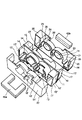
図1には、本発明実施形態によるモジュール式支持物の一例を示すが、これは全体形状が平行六面体の中央モジュール10と、全体形状が平行六面体の2つの端部モジュール20、20’を含む。
【0017】
中央モジュール10は、全体形状が平行六面体の同一外形を有する2つの部材11、11’からなる。
中央モジュール10の各部材11、11’は、後で分かるように、磁気コア40a、40bの脚部を通過させる2つの開口を含む全体が矩形の平らな基部12、12’を含む。
図1には中央モジュール10の部材11’の円筒形の壁13’のみが見えるが、これらの円筒形壁は基部12、12’から突き出て、各々が円形開口を囲んでいる。円筒形壁は部分的にHT変圧器の磁気コア40a、40bと1次巻線(図示せず)用のハウジングとなる。
半円筒形壁14、14’は基部12、12’から突き出て、各円筒形壁1313’を囲み、これらの間に部分的に、HT変圧器の2次巻線(図示せず)を収容するためのハウジングを形成する。
【0018】
また、中央モジュール10の各部材11、11’は、それぞれの一端部に、基部12、12’から突き出て、倍電圧整流回路を収容するための平行六面体の全体形状のハウジング15、15’を部分的に形成する壁を含む。
各部材11、11’は、矩形の端壁16’(これらの1つだけが図1に見える)と、ハウジング15、15’の反対側の端部に矩形の側壁17、17’を備えている。中央モジュールの部材11、11’の端壁と半円筒形壁14、14’の下側とは離れているので、これらは部分的に、倍電圧整流回路を収容するためのハウジング18’(部材11’の上のみに見える)を形成する。
中央モジュールの部材11、11’は、これらの基部12、12’によって背中合せに一緒に、中央モジュール10の中央垂直軸に対して対称に接合されている。
【0019】
ここで端部モジュール20、20’を説明する。これらのモジュールが同じ外形を有すると仮定すれば、説明はこれらのモジュールの1つだけについて行い、その説明がもう1つのモジュールに適用されることは理解されるであろう。
図1に見ることができるように、モジュール20は、平行六面体の全体形状と、中央モジュール10の部材12の外形と相補的な外形を有する。
さらに具体的には、端部モジュール20は、磁気コアの横断脚部40bを収容する凹部22を含む矩形の全体形状を有する基部21を有する。
2つの対称円形開口23が基部21の凹部22に形成されている。
【0020】
円形開口23の各々は、基部から突き出て中央モジュール10の部材11の円筒形壁と相補形の円筒形壁24によって囲まれている。円筒形壁は磁気コア40a、40bのためのハウジングを部分的に構成している。同様に、円筒形壁24の各々は、基部21から突き出た半円筒形壁25によって囲まれ、半円筒形壁25は、中央モジュール10の半円筒形壁14と相補形で、円筒形の突出壁24と共に、HT変圧器の2次巻線のための環状ハウジングを構成している。
【0021】
端部モジュール20はまた、その横方向一端部に、基部21から突き出た壁を有する。これらの壁は、倍電圧整流回路を収容するための平行六面体の全体形状のハウジング26を部分的に決めている。
端部モジュール20はさらに、矩形の全体形状を有する端壁27と、平行六面体のハウジング26と反対側の端部にU形状の側壁28とを含む。
【0022】
図1に示すように、端部モジュール20、20’は、これらが中央モジュール10の対応する部材11、11’全体にわたって合致するような寸法で作られている。とくに端部モジュール20、20’の突出壁は、モジュールが互いに接合されると、中央モジュール10の対応する突出壁に外部から重なる。
また、この逆の形状に作ることができるのは明らかである。必要なら、モジュールをプラスチック製ねじなどのねじによって共に固定することもできよう。
先に説明したように、該当する突出壁は傾斜相補表面を有し、この傾斜相補表面によって、これらの壁は重ねることによって共に密接に合致し、機能エレメントのための該当ハウジングを形成することができる。
【0023】
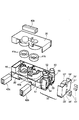
図2に、本発明によるモジュール式支持物の別の実施形態を示すが、HT電源ユニットのHT出力機能エレメントを収容するための追加の第4モジュール50を加えたことのみが、図1のモジュール式支持物と異なる点である。
図2に見ることができるように、モジュールの1つ20’は、ハウジング中に配置された磁気コアの部材40aを中央モジュール10の一部にはめ込む。この図2はまた、HT変圧器の2次巻線41a、41b、およびそれぞれのハウジングに向かっている倍電圧整流回路42a、42bも示す。
【0024】
図2の実施形態における第4モジュール50は、第1部材51と第2部材51’とを含む。全体形状が平行六面体である第1部材は、矩形の基部52と、基部52から突き出て、フィラメント用の変圧器を収容するためのハウジングを部分的に形成する2つの半円形壁53と、半円形壁53の各側面に1つずつ平行六面体の形状のハウジングを構成して、HT出力ソケット60を収容するための壁54、55とを含む。
【0025】
全体形状が平行六面体である第2部材51’は矩形の基部52’を備え、この基部にフィラメント用の変圧器のための2つのハウジングに対応する2つの空洞56’を備えている。
半円形壁53’は、空洞56’に整列して基部52’から突き出ている。第4モジュール50の第1部材51の壁54、55に合わせて基部52’から突き出た壁54’、55’は、空洞56’の両側に1つずつ平行六面体のハウジングを部分的に形成する。
空洞56’は、あぶみ形状の磁気コア61を挿入できるようにするためのものである。
【0026】
第4モジュール50の2つの部材51、51’は、図1における実施形態のモジュールについて説明したように共に嵌め合わせられ、第4モジュール50は、取付け部材、接着、ねじなどの何らかの適切な手段によって適切な側に沿って他のモジュールに連結される。
第4モジュールの各部材は、成形されたプラスチックで作成することが好ましい。
【0027】
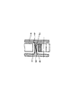
図3は、本発明による機能エレメント用のハウジングを形成する突出壁の外形を線図で示す。
図3に示すように、突出壁1、2は先細の形状であり、この壁が突き出る元の基部3、4から自由端まで壁の厚さは次第に薄くなる。図3に見ることができるように、相補突出壁1、2は、モジュールが共に合致したときに重なる相補傾斜表面5、6を有する。突出壁1、2のこの外形は、これらの重複と合致とを促進して成形作業とくに離型を容易にするのみならず、クリーページ線の長さを増加させることによってハウジング間の電気絶縁を改善し、アーク発生の危険性を低下させる。
【0028】
さらにまた上述のように、突出壁のこの外形は、モジュールの製造許容誤差とは無関係に望みの絶縁量を得ることを可能にする。
モジュールは、相互接続する接続器のすべてを収容するために必要な通路およびカットアウトを含み、こうして強い電界の集中を防ぎ、したがってアーク発生の危険性が低下し、同時に製造コストを軽減する。
【0029】
実施形態中にバイポーラ・ユニットを示したが、本発明はモノポール・ユニットまたはマルチポール・ユニットにも適用可能である。
ここに開示された実施形態の、構造または機能またはステップ、もしくはこれらの任意の組合せにおける様々な変更を、当業者は本発明の範囲を逸脱することなく行うことができる。
本実施形態のモジュール式支持物は高電圧電源すなわち高電圧ユニットの機能エレメントを収納するためのものであって、その機能エレメントを収納させた支持物が接地された金属ボックス内に収納される。その金属ボックスは電気絶縁し冷却する液体で満たされる。
【図面の簡単な説明】
【図1】 モジュール式支持物の一実施形態の分解斜視図である。
【図2】 モジュール式支持物の別の実施形態の分解斜視図である。
【図3】 モジュール式支持物の突出壁の線図である。
【符号の説明】
1、2 相補突出壁、 5、6 相補傾斜表面、 10 中央モジュール、
11 平行六面体の部材、 12 基部、 13 円筒形壁、
14 半円筒形壁、 15 ハウジング、 16、17 端壁、
18 ハウジング、 20 端部モジュール、 21 基部、 22 凹部、
23 円形開口、 24 円筒形壁、 25 半円筒形壁、
26 ハウジング、 27、28 端壁、 40 磁気コア、
41 2次巻線、 42 倍電圧整流回路、 50 第4モジュール、
51 第4モジュールの部材、 52 基部、 53 半円形壁、
54、55 壁、 56 空洞、 61 磁気コア[0001]
BACKGROUND OF THE INVENTION
The present invention particularly relates to a high voltage (HT) power supply unit for an X-ray tube in which all of the high voltage power supply functional components are housed in a single box.
[0002]
[Prior art]
The x-ray tube includes a filament type cathode that emits an electron beam toward the anode. The anode emits an X-ray beam under the action of an electron beam. In order to obtain a high energy electron beam, the electron beam emitted from the cathode is accelerated by a strong electric field created between the cathode and the anode. To achieve this, the anode is raised to a positive potential with respect to the cathode, and the potential difference between the anode and the cathode generally reaches a value of 150 kV or higher. These extremely high potential differences can be obtained with high voltage devices.
The functional elements of these high voltage devices are housed in a grounded metal box filled with a liquid that provides electrical insulation and cooling.
[0003]
The functional element typically includes a high transformation ratio HT transformer that includes a first winding, a second winding, a magnetic core, an HT rectifier, and an HT smoothing capacitor.
More specifically, the transformer has a primary winding to which an AC voltage supplied by a frequency converter is applied, and a secondary winding connected to a voltage doubler rectifier circuit. Since the voltage doubler rectifier circuits of each secondary winding are connected together, these voltages are combined. Considering the polarity of the rectifier, a positive or negative voltage can be applied to obtain the high voltage level necessary to power the x-ray tube.
[0004]
The high voltage output section in the HT unit is protected by a resistor connected to an HT connector that is hermetically sealed through the HT box cover plate, and a socket that accommodates the connector pin of the HT lead wire holds the HT device. Connect to X-ray tube. The HT output unit is also connected to the voltage dividing resistor inside the HT unit. The voltage divider resistor forms the top of the voltage divider that supplies a low voltage proportional to the level of the high voltage that is output.
Inside the box are also the conductors necessary to make the electrical connection between the functional elements and to electrically connect the HT power supply to the X-ray tube.
All of the functional elements are supported inside the box and need to be electrically isolated from each other.
[0005]
[Problems to be solved by the invention]
Therefore, the present invention provides a support for the functional element of the HT unit that provides both support for the functional element and their electrical insulation, and includes a minimum number of members and is easy to manufacture and low cost. It is an issue to provide.
[0006]
More particularly, the present invention is a modular support for a high voltage power supply unit, wherein all functional components of the high voltage power supply are made of an insulating material in the high voltage power supply unit. And the modular support and functional component together provide a modular support disposed in a single grounded metal box filled with an electrically insulating fluid that facilitates heat conduction. Is an issue.
[0007]
Another subject of the present invention is a functional element of the HT unit described above, in which all of the components of the HT transformer, the voltage doubler rectifier circuit, the resistor box of the voltage divider and the output protection resistor are combined. Is to provide a support for.
[0008]
Yet another subject matter of the present invention is to provide a support as described above which also incorporates an HT output unit that incorporates an HT output socket, a filament transformer, and possibly an HT output commutator.
[0009]
[Means for Solving the Problems]
The above object includes a housing having an electrically insulated wall and containing a functional element of an HT power supply unit, the electrically insulated wall of the housing being separated by two protruding walls having overlapping complementary inclined surfaces. This is accomplished by providing a modular support for the HT power supply unit being formed.
[0010]
In one embodiment of the invention, a modular support for an HT power supply unit, particularly for powering an X-ray tube,
A central module formed of two members of the same outline, having a base and a wall protruding from the base, the two members being joined symmetrically with respect to the central vertical axis of the central module by these bases When,
A first end module and a second end module of the same outline, each having a base and a wall protruding from the base, wherein the projecting walls of the central module, the first module and the second module have inclined complementary surfaces. And when each of the first and second end modules is combined with one of the members of the central module, the corresponding housing projecting walls of the module are intimately joined to each other by the overlap of complementary inclined surfaces, A first end module and a second end module forming a housing for housing the functional elements. In this way, a support for the functional elements of the HT power supply unit arranged in the housing and appropriate electrical insulation is provided.
[0011]
In general, the modular support comprises a housing for the magnetic core of the primary and secondary windings of the HT transformer, a housing for the voltage doubler rectifier circuit, and a housing for the resistor of the voltage divider.
It is quite obvious that each module of the modular support has the necessary passages to electrically connect the various functional elements.
[0012]
In another embodiment of the present invention, the modular support includes a fourth module that includes a first member and a second member of complementary contours each having a base and projecting walls projecting from the base, which are HT. This constitutes another housing for the functional element of the output unit, the first member of this fourth module is joined to the side wall of the central module by its base, and the first member and the second member of this fourth module are joined together Then, the corresponding projecting walls of the members of the fourth module overlap to insulate the functional element from the output unit.
[0013]
Generally, this fourth module includes a housing for the HT output socket and a housing for the transformer for powering the cathode.
Due to the overlap of the corresponding protruding walls forming the housing, the length of the creepage line is increased, so that the insulation of the housing is increased and the risk of arcing is reduced.
[0014]
As described above, the protruding walls of the module have inclined complementary overlapping surfaces, i.e., complementary overlapping surfaces where the thickness of these walls decreases uniformly from the base of the module, i.e. from the module member to its free end. Therefore, it becomes easy to match modules and module members with each other, and it becomes easy to manufacture by molding, and in particular, mold release becomes easy. It is further important that the presence of these complementary inclined surfaces ensure a proper fit regardless of the manufacturing tolerances (diameter and height) of the protruding wall from an electrical and mechanical point of view.
[0015]
Furthermore, since the final insulating wall of the housing consists of two separate walls that overlap, the reliability of the electrical insulation is improved even if there is a non-uniform area due to dielectrics in one of the protruding walls. . This is because the probability that two non-uniform regions in each of the overlapping walls exist facing each other is practically impossible.
The module and module member are preferably molded from plastic.
[0016]
DETAILED DESCRIPTION OF THE INVENTION
FIG. 1 shows an example of a modular support according to an embodiment of the present invention, which includes a
[0017]
The
Each
In FIG. 1, only the
[0018]
Further, each
Each
The
[0019]
Here, the
As can be seen in FIG. 1, the
More specifically, the
Two symmetrical circular openings 23 are formed in the
[0020]
Each of the circular openings 23 protrudes from the base and is surrounded by a
[0021]
The
The
[0022]
As shown in FIG. 1, the
Obviously, it can be made in the opposite shape. If necessary, the modules could be secured together with screws such as plastic screws.
As explained above, the corresponding projecting wall has a sloped complementary surface, which allows the walls to closely fit together by overlapping to form a corresponding housing for the functional element. it can.
[0023]
FIG. 2 shows another embodiment of the modular support according to the present invention, but only with the addition of an additional
As can be seen in FIG. 2, one of the
[0024]
The
[0025]
The second member 51 ', which has a parallelepiped overall shape, comprises a rectangular base 52', which has two cavities 56 'corresponding to the two housings for the filament transformer.
The
The
[0026]
The two
Each member of the fourth module is preferably made of molded plastic.
[0027]
FIG. 3 shows diagrammatically the outline of the protruding wall forming the housing for the functional element according to the invention.
As shown in FIG. 3, the protruding
[0028]
Furthermore, as mentioned above, this profile of the protruding wall makes it possible to obtain the desired amount of insulation irrespective of the manufacturing tolerances of the module.
The module includes the passages and cutouts necessary to accommodate all of the interconnecting connectors, thus preventing strong electric field concentration, thus reducing the risk of arcing and at the same time reducing manufacturing costs.
[0029]
Although a bipolar unit is shown in the embodiment, the present invention is also applicable to a monopole unit or a multipole unit.
Various changes in structure or function or step, or any combination thereof, of the embodiments disclosed herein may be made by those skilled in the art without departing from the scope of the invention.
The modular support of the present embodiment is for housing a functional element of a high voltage power source, that is, a high voltage unit, and the support housing the functional element is housed in a grounded metal box. The metal box is filled with an electrically insulating and cooling liquid.
[Brief description of the drawings]
FIG. 1 is an exploded perspective view of one embodiment of a modular support.
FIG. 2 is an exploded perspective view of another embodiment of a modular support.
FIG. 3 is a diagram of a protruding wall of a modular support.
[Explanation of symbols]
1, 2 Complementary protruding wall, 5, 6 Complementary inclined surface, 10 Center module,
11 parallelepiped members, 12 bases, 13 cylindrical walls,
14 semi-cylindrical wall, 15 housing, 16, 17 end wall,
18 housing, 20 end module, 21 base, 22 recess,
23 circular opening, 24 cylindrical wall, 25 semi-cylindrical wall,
26 housing, 27, 28 end wall, 40 magnetic core,
41 secondary winding, 42 voltage doubler rectifier circuit, 50 fourth module,
51 fourth module member, 52 base, 53 semicircular wall,
54, 55 wall, 56 cavity, 61 magnetic core
Claims (7)
同一外形の2つの部材(11、11’)から形成されて、基部(12、12’)とその基部(12、12’)から突き出た壁(13、13’;14、14’;15、15’)を有し、これら2つの部材(11、11’)がそれぞれの基部によって中央モジュールの中央垂直軸に対して互いに対称に接合されている中央モジュール(10)と、
各々が基部(21、21’)とその基部から突き出た壁(24、25、26)を有する同一外形の第1端部モジュール(20)と第2端部モジュール(20’)であって、中央モジュールと第1モジュールと第2モジュールとの前記の突出壁は傾斜した相補表面を有して、第1および第2の端部モジュールの各々を中央モジュールの部材の1つと組み合わせたときに、モジュールの対応するハウジングの突出壁が相補傾斜表面の重なりによって互いに密に接合し、HT電源ユニットの機能エレメントを収容するためのハウジングを形成する第1端部モジュール(20)と第2端部モジュール(20’)とを含む高電圧電源ユニット用のモジュール式支持物。Has an electrically insulating walls, a high voltage (HT) Modular supporting structure for including a high voltage power supply unit housing that houses the functional elements of the power supply unit,
Formed from two members (11, 11 ′) having the same outer shape, a base (12, 12 ′) and a wall (13, 13 ′; 14, 14 ′; 15, protruding from the base (12, 12 ′), A central module (10) having these two members (11, 11 ') joined symmetrically with respect to the central vertical axis of the central module by respective bases;
A first end module (20) and a second end module (20 ') of the same profile, each having a base (21, 21') and a wall (24, 25, 26) protruding from the base; The protruding walls of the central module, the first module and the second module have inclined complementary surfaces, and when each of the first and second end modules is combined with one of the members of the central module, A first end module (20) and a second end module, in which the projecting walls of the corresponding housing of the module are tightly joined to each other by the overlap of complementary inclined surfaces to form a housing for accommodating the functional elements of the HT power supply unit (20 ') a modular support for a high voltage power supply unit.
Applications Claiming Priority (2)
| Application Number | Priority Date | Filing Date | Title |
|---|---|---|---|
| FR9712607 | 1997-10-09 | ||
| FR9712607A FR2769787B1 (en) | 1997-10-09 | 1997-10-09 | MODULAR SUPPORT FOR THE FUNCTIONAL ELEMENTS OF A HIGH-VOLTAGE POWER SUPPLY AND THE BLOCK THUS OBTAINED |
Publications (3)
| Publication Number | Publication Date |
|---|---|
| JPH11219798A JPH11219798A (en) | 1999-08-10 |
| JPH11219798A5 JPH11219798A5 (en) | 2008-08-07 |
| JP4222663B2 true JP4222663B2 (en) | 2009-02-12 |
Family
ID=9512018
Family Applications (1)
| Application Number | Title | Priority Date | Filing Date |
|---|---|---|---|
| JP28762098A Expired - Fee Related JP4222663B2 (en) | 1997-10-09 | 1998-10-09 | Modular supports for functional elements of high-voltage power supply units and the resulting units |
Country Status (7)
| Country | Link |
|---|---|
| US (1) | US6115236A (en) |
| EP (1) | EP0909012B1 (en) |
| JP (1) | JP4222663B2 (en) |
| KR (1) | KR100660307B1 (en) |
| CN (1) | CN1185910C (en) |
| CA (1) | CA2249496C (en) |
| FR (1) | FR2769787B1 (en) |
Families Citing this family (13)
| Publication number | Priority date | Publication date | Assignee | Title |
|---|---|---|---|---|
| FR2784261B1 (en) * | 1998-10-05 | 2001-07-27 | Ge Medical Syst Sa | INCREASED ELECTRICAL INSULATION AND COOLING MATERIAL FOR THERMAL CONDUCTIVITY AND APPLICATION TO THE INSULATION OF A HIGH VOLTAGE SUPPLY DEVICE |
| USD488128S1 (en) | 2002-05-06 | 2004-04-06 | Cyber Power System Inc. | Support for a power supply device |
| US8084686B2 (en) * | 2009-05-29 | 2011-12-27 | Cooper Technologies Company | Stackable power distribution box |
| USD609182S1 (en) * | 2009-05-29 | 2010-02-02 | Cooper Technologies Company | Platform for a power distribution box |
| KR101039276B1 (en) * | 2010-04-23 | 2011-06-07 | 주식회사 시스하이텍 | Slim high voltage transformer |
| KR100978503B1 (en) * | 2010-04-23 | 2010-08-31 | 주식회사 시스하이텍 | Slim type high voltage transformer |
| CN102905454A (en) * | 2011-07-28 | 2013-01-30 | 通用电气公司 | Modular high-voltage power generation system |
| CN103580451B (en) * | 2012-08-08 | 2016-06-01 | 群光电能科技股份有限公司 | Combined power supply device and power supply system with combined power supply device |
| DE102013200448A1 (en) * | 2013-01-15 | 2014-07-17 | Bayerische Motoren Werke Aktiengesellschaft | Cooling device, in particular for battery modules, and vehicle, comprising such a cooling device |
| KR102070051B1 (en) * | 2013-06-17 | 2020-01-29 | 삼성전자 주식회사 | Inductor and electronic device including the same |
| KR101337542B1 (en) * | 2013-09-13 | 2013-12-06 | 국방과학연구소 | Electric propulsion system of electric vehicle |
| AU2014364347B2 (en) * | 2014-01-28 | 2018-04-19 | Sociedad Espanola De Electromedicina Y Calidad, S.A. | High-voltage, high-frequency and high-power transformer |
| KR20220133639A (en) * | 2021-03-25 | 2022-10-05 | 엘에스일렉트릭(주) | Enclosure for isolated converter and isolated converter using the same |
Family Cites Families (13)
| Publication number | Priority date | Publication date | Assignee | Title |
|---|---|---|---|---|
| DE3440756A1 (en) * | 1984-11-08 | 1986-05-07 | CEAG Licht- und Stromversorgungstechnik GmbH, 6800 Mannheim | POWER SUPPLY |
| JPS6489197A (en) * | 1987-09-30 | 1989-04-03 | Toshiba Corp | X-ray device |
| US5077771A (en) * | 1989-03-01 | 1991-12-31 | Kevex X-Ray Inc. | Hand held high power pulsed precision x-ray source |
| FR2655231B1 (en) * | 1989-11-24 | 1992-02-14 | Gen Electric Cgr | HIGH VOLTAGE BLOCK FOR X-RAY TUBE WITH COOLING TANK INTEGRATED IN THE SECONDARY CIRCUIT. |
| EP0429315B1 (en) * | 1989-11-24 | 1995-05-10 | Communications & Power Industries, Inc. | High voltage high power DC power supply |
| US5416837A (en) * | 1990-05-15 | 1995-05-16 | Siecor Puerto Rico, Inc. | Telephone network interface enclosure |
| US5185691A (en) * | 1991-03-15 | 1993-02-09 | Compaq Computer Corporation | Thermal packaging for natural convection cooled electronics |
| FR2680938B1 (en) * | 1991-09-03 | 1993-11-26 | General Electric Cgr Sa | RADIOGENIC BLOCK WITH HIGH VOLTAGE SUPPLY DEVICE INTEGRATED IN THE SHEATH. |
| DE4142371C2 (en) * | 1991-12-20 | 2003-11-13 | Siemens Ag | X-ray tube with a molded body for sealing and electrical insulation of two electrically conductive housing parts |
| DE4209202C2 (en) * | 1992-03-19 | 1995-10-12 | Hofmann Gmbh Elektr Fritz | Plant for generating high DC voltage |
| JPH06111991A (en) * | 1992-09-29 | 1994-04-22 | Hitachi Medical Corp | X-ray generator |
| US5481438A (en) * | 1994-09-06 | 1996-01-02 | Shinon Denkisangyo Kabushiki Kaisha | Tray for semiconductor devices |
| JP3355081B2 (en) * | 1995-02-16 | 2002-12-09 | 矢崎総業株式会社 | Waterproof case |
-
1997
- 1997-10-09 FR FR9712607A patent/FR2769787B1/en not_active Expired - Fee Related
-
1998
- 1998-10-01 CA CA002249496A patent/CA2249496C/en not_active Expired - Fee Related
- 1998-10-08 KR KR1019980041952A patent/KR100660307B1/en not_active Expired - Fee Related
- 1998-10-08 US US09/168,843 patent/US6115236A/en not_active Expired - Lifetime
- 1998-10-09 EP EP98308247A patent/EP0909012B1/en not_active Expired - Lifetime
- 1998-10-09 CN CNB981231233A patent/CN1185910C/en not_active Expired - Fee Related
- 1998-10-09 JP JP28762098A patent/JP4222663B2/en not_active Expired - Fee Related
Also Published As
| Publication number | Publication date |
|---|---|
| JPH11219798A (en) | 1999-08-10 |
| FR2769787A1 (en) | 1999-04-16 |
| CN1185910C (en) | 2005-01-19 |
| KR100660307B1 (en) | 2007-04-25 |
| US6115236A (en) | 2000-09-05 |
| KR19990036923A (en) | 1999-05-25 |
| EP0909012A1 (en) | 1999-04-14 |
| CA2249496C (en) | 2006-05-30 |
| CA2249496A1 (en) | 1999-04-09 |
| EP0909012B1 (en) | 2012-05-09 |
| CN1228006A (en) | 1999-09-08 |
| FR2769787B1 (en) | 1999-12-24 |
Similar Documents
| Publication | Publication Date | Title |
|---|---|---|
| JP4222663B2 (en) | Modular supports for functional elements of high-voltage power supply units and the resulting units | |
| US4039900A (en) | Plug in regulating power supply | |
| US20090102593A1 (en) | Coil form | |
| US3371302A (en) | Power supply and improved transformer structure therefor | |
| US5463999A (en) | Ignition coil unit for an internal combustion engine and manufacturing method of the same | |
| US5959407A (en) | Vehicle lighting drive apparatus | |
| US20190066906A1 (en) | Power conversion device | |
| US6650218B1 (en) | Inverter transformer | |
| US7132769B2 (en) | Capacitor motor with terminal arrangement | |
| JP4541387B2 (en) | Socket for discharge lamp | |
| KR101039276B1 (en) | Slim high voltage transformer | |
| KR100978503B1 (en) | Slim type high voltage transformer | |
| JPH11219798A5 (en) | ||
| WO2012042707A1 (en) | Insulating transformer | |
| US5973307A (en) | High voltage transformer with side insulation support and formed with through-holes for lead wires | |
| US6414580B1 (en) | Electrical noise suppressing device for motors | |
| JP2019145719A (en) | module | |
| JP2567974B2 (en) | Discharge lamp lighting device | |
| JP7629067B1 (en) | Isolated Converter | |
| MXPA98008355A (en) | Modular support for the functional elements of a high voltage energy supply unit and obten unit | |
| JP2017139287A (en) | Coil parts and power supply | |
| JP3601070B2 (en) | lighting equipment | |
| KR102143867B1 (en) | SLIM TRANSFORMER FOR PFC(Power Factor Correction) | |
| JP2004336007A (en) | High voltage transformer and microwave oven using the high voltage transformer | |
| US5844778A (en) | High-voltage electronic device |
Legal Events
| Date | Code | Title | Description |
|---|---|---|---|
| RD02 | Notification of acceptance of power of attorney |
Free format text: JAPANESE INTERMEDIATE CODE: A7422 Effective date: 20050812 |
|
| RD04 | Notification of resignation of power of attorney |
Free format text: JAPANESE INTERMEDIATE CODE: A7424 Effective date: 20050815 |
|
| A621 | Written request for application examination |
Free format text: JAPANESE INTERMEDIATE CODE: A621 Effective date: 20051005 |
|
| A521 | Request for written amendment filed |
Free format text: JAPANESE INTERMEDIATE CODE: A523 Effective date: 20080619 |
|
| TRDD | Decision of grant or rejection written | ||
| A01 | Written decision to grant a patent or to grant a registration (utility model) |
Free format text: JAPANESE INTERMEDIATE CODE: A01 Effective date: 20081021 |
|
| A01 | Written decision to grant a patent or to grant a registration (utility model) |
Free format text: JAPANESE INTERMEDIATE CODE: A01 |
|
| A61 | First payment of annual fees (during grant procedure) |
Free format text: JAPANESE INTERMEDIATE CODE: A61 Effective date: 20081118 |
|
| R150 | Certificate of patent or registration of utility model |
Free format text: JAPANESE INTERMEDIATE CODE: R150 |
|
| FPAY | Renewal fee payment (event date is renewal date of database) |
Free format text: PAYMENT UNTIL: 20111128 Year of fee payment: 3 |
|
| FPAY | Renewal fee payment (event date is renewal date of database) |
Free format text: PAYMENT UNTIL: 20121128 Year of fee payment: 4 |
|
| FPAY | Renewal fee payment (event date is renewal date of database) |
Free format text: PAYMENT UNTIL: 20131128 Year of fee payment: 5 |
|
| LAPS | Cancellation because of no payment of annual fees |