JP4221069B2 - Interior trim mounting structure - Google Patents
Interior trim mounting structure Download PDFInfo
- Publication number
- JP4221069B2 JP4221069B2 JP02215498A JP2215498A JP4221069B2 JP 4221069 B2 JP4221069 B2 JP 4221069B2 JP 02215498 A JP02215498 A JP 02215498A JP 2215498 A JP2215498 A JP 2215498A JP 4221069 B2 JP4221069 B2 JP 4221069B2
- Authority
- JP
- Japan
- Prior art keywords
- trim
- panel
- clip
- interior trim
- engaging
- Prior art date
- Legal status (The legal status is an assumption and is not a legal conclusion. Google has not performed a legal analysis and makes no representation as to the accuracy of the status listed.)
- Expired - Lifetime
Links
Images


Landscapes
- Connection Of Plates (AREA)
Description
【0001】
【発明の属する技術分野】
本発明は、パネルに対してトリムを取着係合するためのクリップとこのクリップによるトリムの取着構造に関し、特に自動車の内装トリムをボディパネルに取着する構造に関する。
【0002】
【従来の技術】
従来、自動車の乗員室内や荷室内に、内装トリムを取着して鋼板パネルを覆うことが一般的である。これは、繊維質、樹脂質、あるいはこれらの組み合わせにより成形された内装トリムにより、鋼板パネルに欠ける意匠性、柔らかい触感、吸音性等の特性を補うためである。
【0003】
この種の内装トリムを自動車の鋼板パネルに取着するには、各種のクリップを内装トリムに取着して、このクリップを鋼板パネルの開口や端縁フランジに、ネジ留め、ファスナ留め、あるいは粘着材等により固定することで、鋼板パネルと内装トリムを取着していた。
【0004】
しかしながら、パネルへの内装トリムの組付作業においては、以下の問題が生じることがある。
【0005】
まず、鋼板パネルと内装トリムの係合のためのクリップの取着位置が、組付作業者の手の届きにくい所である設計であったり、組付作業者の姿勢が極めて肉体的負荷の大きな姿勢となる設計となる場合がある。
【0006】
また、鋼板パネルに内装トリムを取着する際、当然のこととして、パネルの表面に内装トリムが重なるため、鋼板パネルの取着用開口等が組付作業者に見えなくなり、手探りによる位置確認となり作業時間が掛かってしまう。あるいは内装トリムを鋼板パネルの取付位置に保持しながら、多数のクリップを携行する、あるいはクリップを身近に配置した組付作業者が、これらのクリップを1個ずつ内装トリムを取着することにより、作業効率の低下を招いてしまう。
【0007】
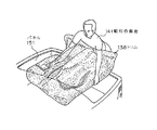
これを解決する一つの方法として、図12に示すように、弾性のあるトリムを断面形状を所要形状より開き気味に成形したトリム138が提案されている(米国特許第4673207号明細書参照)。このトリム138の取着方法の概略を図13を用いて、以下に説明する。
【0008】
まず、取付時はトリム138を作業者141が弾性変形させ、次にパネル151に取着する状態で、作業者141がトリム138から手を放すことで、トリム138は成形時の図12に示した開き気味の形状に戻ろうとする。この際、トリム138の側壁がパネル151に対して突っ張る状態となることで、トリム138はパネル151に対して固定されることとなる。
【0009】
このようにすることで取着用のクリップを無くす、あるいは少なくするというものである。
【0010】
【発明が解決しようとする課題】
しかしながら、トリムが上壁を有し、特に側壁間のスパンが長い構造等の場合、上壁はクリップ無しの突っ張り力だけでは、上壁の自重を支えることができず、垂れ下がってきてしまい、結局、クリップを完全に無くすことは困難である等の問題を有していた。
【0011】
そこで、本発明はパネルにトリムを容易に取着することができる、トリム取着用クリップ及びトリム取着用クリップによるトリム取着構造を提供する。
【0014】
【課題を解決するための手段】
上記目的を達成するため本発明のトリム取着構造は、自動車の鋼板パネルと、中間部および先端部に幅広部を有する長尺開口が形成された内装トリムと、前記鋼板パネルに前記内装トリムを取着するためのクリップとを有する内装トリム取着構造であって、前記クリップには、基板部と、前記基板部の一主面の一端側に形成され前記内装トリムの長尺開口の幅広部に係合可能なトリム係合部と、前記基板部の一主面の他端側に形成され前記鋼板パネルと係合するパネル係合部とが設けられ、前記クリップのトリム係合部を前記内装トリムの長尺開口にその長手方向後端から挿入して前記中間部の幅広部に係合させた後、前記内装トリムを前記鋼板パネルに対して位置合わせした状態で、前記基板部を前記長尺開口の先端部に向けて押し込んで前記トリム係合部を前記長尺開口の先端部の幅広部に係合させることによって、前記パネル係合部が前記鋼板パネルに係合されるものである。
【0015】
上記本発明の内装トリム取着構造において、内装トリムは、クリップを収納するように表面側に膨出した膨出部を有し、かつクリップの基板部が内装トリムの裏面側に組付けられるものでもよい。また、パネル係合部は、基板部の一主面から突出する立ち上がり板と、立ち上がり板に、トリム係合部に向かって延出し、かつ、前記鋼板パネルが挿入可能な間隔をおいて形成され中間部で互いの間隔が狭くなるように折曲された2枚の折曲板とを有するものとし、さらに鋼板パネルに、基板部を長尺開口の先端部に向けて押し込んでトリム係合部を長尺開口の先端部の幅広部に係合させることによって、前記2枚の折曲板の少なくとも一方の折曲部が係合される開口が形成されているものでもよい。
【0016】
上記のように構成された本発明では、まず内装トリムを鋼板パネルに取着する前に、クリップのトリム係合部を内装トリムの長尺開口の後端から挿入し、その中間部の幅広部で保持させる。次いで、内装トリムを鋼板パネルに対して位置合わせ(仮組み)し、その状態でクリップを、トリム係合部が内装トリムの長尺開口の先端部の幅広部に係合するように押し込む。これにより、クリップは内装トリムに完全に係合されるとともに、クリップのパネル係合部が鋼板パネルに係合され、よって内装トリムが鋼板パネルに取着されることとなる。
【0017】
このように、内装トリムを鋼板パネルに仮組みする際には、クリップが内装トリムに保持されているので作業者はクリップを押さえておく必要はない。また、クリップを鋼板パネルに係合させるに際しては、内装トリムは鋼板パネルに対して位置合わせされており、クリップを単に押し込むだけでよいので、その作業は簡単である。また、本発明の内装トリム取着構造において、クリップは室内側に突出せず膨出部に収納される構成とすることにより、組付け作業者あるいは自動車の使用者がクリップに衣類あるいは荷物等を引っ掛けてしまう恐れがなくなる。
【0018】
【発明の実施の形態】
次に、本発明の実施の形態について図面を参照して説明する。
【0019】
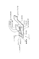
図1は、本発明によるトリム取着用のクリップの一実施形態の斜視図であり、ポリエチレン、ポリプロピレン、ナイロンなどの可塑性樹脂を射出成形して得られるものである。
【0020】
このクリップ13は、基板部1と、基板部1のクリップ前縁12の近傍に形成されたトリム係合部4と、その後方に形成されたパネル係合部8とにより基本的な構成がなされている。基板部1の後部は突押部11を介してスライドガイド部10へと繋がっている。
【0021】
トリム係合部4は、一主面である基板部上面1aから突出した連結部3を介して、基板部1と間隔をあけて支持される板状の係合リブ2を有する。連結部3は基板部1よりも幅狭であり、係合リブ2は連結部3よりも幅広となっている。
【0022】
パネル係合部8は、基板部上面1aより突出する立ち上がり板5と、立ち上がり板5の上端部からトリム係合部4に向かって延出する上折曲板6と、立ち上がり板5の中間部からトリム係合部4に向かって延出する下折曲板7とで構成される。上折曲板6は先端部が上方に向くように先端側曲り部14で屈曲しており、また下折曲板7は先端部が下方に向くように曲り部15で屈曲している。上折曲板6と下折曲板7とは、それぞれ上下に並設されており、上折曲板6と下折曲板7とで、空間部であるスリット9が形成され、上折曲板6と下折曲板7の延出方向中間部では両者の間隔が狭くなっている。
【0023】
スライドガイド部10は、基板部1の後部から斜め上方に延出する突押部11を介して、基板部1と平行な平板状に形成されている。
【0024】
なお、基板部1を基準面としたときのスライドガイド部10、パネル係合部8及びトリム係合部4の高さ方向の関係は、スライドガイド部10の高さが最も高く、次いでパネル係合部8、トリム係合部4の順となる構成をなしている。
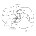
【0025】
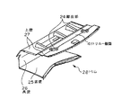
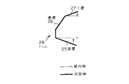
図2は本発明のクリップ13による取付に適したトリム28の概略外観図である。図2のトリム28は自動車の荷室用であり、底壁25と奥壁26と上壁27より構成され、自動車の荷室に沿った形状を有するが、組付け前の形状は図3の実線で示すように底壁25及び上壁27が若干開き気味に成型されている。このため、自動車のボディの一部を構成する鋼板製のパネル71(図7及び図11参照)に組付ける状態で組付作業者が手を放しても、トリム28自身が2点鎖線で示す組付け時の形状から実線で示す成型時の形状へと戻ろうとすることで、パネルに仮留めされることとなる。トリム28の素材として好ましいのは繊維をニードリングして形成した不織布に低融点の繊維やバインダを含み、加熱成形可能とした素材である。上壁27には上方に向かってトリム一般面41より膨出した膨出部24が形成され、この膨出部にトリム28の取着用のクリップ13が収められる。
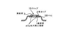
【0026】
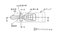
図4はトリム28の膨出部24近傍の拡大斜視図である。膨出部24は、トリム28の段差部40に設けられ、また、トリム一般面41より上方に膨出成型され、クリップ13が納まる幅と高さを有する。膨出部上面43にはクリップ13のトリム係合部4を受け入れる長尺開口47が形成されている。この長尺開口47はクリップ13のトリム係合部4の係合リブ2より幅の広い挿入部44と、挿入部44と対向する最奥部の固定部46と、挿入部44と固定部46の中間に設けられた仮留め部45とからなる。挿入部44と仮留め部45の間は開口の幅が狭くなっている。また膨出部斜面42にはパネル係合部8より幅広で、かつパネル係合部8の高さより高い逃げ開口48が形成されている。長尺開口47と逃げ開口48は連続した開口であり、クリップ用開口49を形成している。
【0027】
上述したクリップ13を用いてトリム28をパネル71に取着するには、クリップ13をトリム28に仮留めした後、クリップ13が仮留めされたトリム28をパネル71に位置合わせ(仮組み)し、その状態でクリップ13をトリム28に固定することによってクリップ13をパネル71に係合させる。これによりトリム28はクリップ13によりパネル71に取着されることになる。
【0028】
以下にトリム28の取着動作について、図5ないし図11を参照して説明する。
【0029】
図5はトリム28にクリップ13が仮留めされている状態の、膨出部24近傍の拡大斜視図であり、図6は図5の膨出部24の上面図、図7は図6のB−Bでの断面図、図8は図6のA−Aでの断面図である。また図9はクリップ13がトリム28の固定部46に係合された状態の、膨出部24近傍の拡大斜視図であり、図10は図9の膨出部24の上面図、図11は図10のB−Bでの断面図である。
【0030】
図5ないし図8を用いて、長尺開口へのクリップの係合を説明する。
【0031】
まず、クリップ13の係合リブ2をトリム28の下側から長尺開口47の挿入部44に挿入する。この状態で、トリム下面74に基板部上面1a及びスライドガイド部10が突き当たることとなる。この状態からさらに、組付作業者はクリップスライド方向に突押部11を指で突き押す。これにより、クリップ13は、上下方向には、係合リブ2と基板部1でトリム28を挟むことによる規制およびスライドガイド部10とトリム下面74による規制を受けながら、また左右方向には連結部3が長尺開口側部47aによる規制を受けながら、仮留め部45まで、クリップスライド方向にスライドされ、仮留めされることとなる。これは上述したように、挿入部44と仮留め部45の間は開口の幅が狭くなっているため、仮留め部45に進入してきた連結部3は、組付作業者がさらに強い力で突押部11を押すまで一旦仮留め部45に仮留めされることとなる。またパネル係合部8の上折曲板6及び下折曲板7は逃げ開口48から突出した状態になっている。
【0032】
このトリム28にクリップ13が係合された状態で、上折曲板6の先端部分がパネルのクリップ差込用開口73に入り込むように仮組みする。この時、組付作業者はクリップ差込用開口73とパネル係合部8の相対的位置を目視確認せずとも、上折曲板6の先端部分がクリップ差込用開口73にはまりこむ感触があるため、容易な位置合わせが可能となる。
【0033】
次に図9ないし図11を用いてクリップ13によるトリム28とパネル71の係合について説明する。
【0034】
図7のようにクリップ13がトリム28の仮留め部45に装着された状態から、組付作業者がクリップスライド方向に突押部11をさらに指で突き押すことにより、クリップ13は上述した規制を受けながら固定部46までスライドされ、クリップ13とトリム28が係合される。この時、上折曲板6及び下折曲板7はその間隙であるスリット9にパネル71を挟み込み、最終的にクリップ抜止用開口72に上折曲板6の先端側曲り部14及び下折曲板7の曲り部15がはまりこみ、クリップ13とパネル71が係合される。
【0035】
以上により、組付作業者はトリム28をパネル71に対して仮組みする際、クリップ13はトリム28の仮留め部45で保持されているので、クリップ13の保持にわずらわされることなく、トリム28の持ちやすい部位を持ち、仮組み作業が行えることとなる。さらにトリム28をパネル71に取着係合して本組みする際、クリップ13を押し込むだけでパネル係合部8をパネル71に係合できるので、パネル71のクリップ差込用開口73の位置の目視確認が不要となる。その結果、パネル71とクリップ13とを係合し損なったり、係合に手間取ったりすることがなくなり、組付け作業効率が向上する。
【0036】
また膨出部24にクリップ13が収納される構成であるため、トリム28が自動車の室内面あるいは荷室内面にクリップ13が突出することがない。その結果、組付け作業者あるいは自動車の使用者が、クリップ13に衣類等を引っ掛ける、あるいは荷物を引っ掛けてしまうことがない。
【0037】
【発明の効果】
以上説明したように本発明は、トリム係合部およびパネル係合部が設けられたクリップによって、クリップが仮留めされた状態で内装トリムを鋼板パネルに位置合わせし、さらに、クリップを押し込むことによってクリップが鋼板パネルと係合する構成となっているので、クリップの取付け位置がどのような位置であっても、内装トリムを鋼板パネルに容易に取着することができる。
【図面の簡単な説明】
【図1】本発明のトリム取着用のクリップの一実施形態の斜視図である。
【図2】本発明のクリップ取着に適したトリムの構成の一例を説明する概略外観図である。
【図3】図3のトリムの断面を説明する概略図である。
【図4】図3の膨出部の拡大斜視図である。
【図5】トリムの仮留め部にトリムが係合されている状況を説明する膨出部の拡大斜視図である。
【図6】トリムの仮留め部にトリムが係合されている状況を説明する膨出部の上面図である。
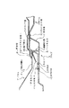
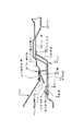
【図7】図6のB−Bにおける断面図である。
【図8】図6のA−Aにおける断面図である。
【図9】トリムの固定部にトリムが係合されている状況を説明する膨出部の拡大斜視図である。
【図10】トリムの固定部にトリムが係合されている状況を説明する膨出部の上面図である。
【図11】図10のB−Bにおける断面図である。
【図12】従来のトリムの断面形状を示す概略図である。
【図13】図12に示した従来のトリムと、パネルの係合作業の状況を説明する図である。
【符号の説明】
1 基板部
1a 基板部上面
2 係合リブ
3 連結部
4 トリム係合部
5 立ち上り板
6 上折曲板
7 下折曲板
8 パネル係合部
9 スリット
10 スライドガイド部
11 突押部
12クリップ前縁
13、123 クリップ
14 先端側曲り部
15 曲り部
24 膨出部
25 底壁
26 奥壁
27 上壁
28、128、138 トリム
40 段差部
41 トリム一般面
42 膨出部斜面
43 膨出部上面
44 挿入
45 仮留め部
46 固定部
47 長尺開口
47a 長尺開口部
48 逃げ開口
49 クリップ用開口
71、151 パネル
72 クリップ抜止用開口
73 クリップ差込用開口
74 トリム下面
121、141 組付作業者[0001]
BACKGROUND OF THE INVENTION
The present invention relates to a clip for attaching and engaging a trim to a panel and a structure for attaching a trim using the clip, and more particularly to a structure for attaching an interior trim of an automobile to a body panel.
[0002]
[Prior art]
Conventionally, it is common to install an interior trim in an automobile passenger compartment or a cargo compartment to cover a steel plate panel. This is because the interior trim formed from fiber, resin, or a combination thereof supplements characteristics such as design, soft touch, and sound absorption that are lacking in the steel sheet panel.
[0003]
To attach this type of interior trim to an automotive steel panel, attach various clips to the interior trim and screw, fasten, or stick the clip to the opening or edge flange of the steel panel. The steel panel and the interior trim were attached by fixing with materials.
[0004]
However, in assembling the interior trim to the panel, the following problems may occur.
[0005]
First, the mounting position of the clip for engaging the steel plate panel and the interior trim is designed so that it is difficult to reach the assembly operator's hand, or the posture of the assembly operator is extremely heavy. There is a case where the design becomes an attitude.
[0006]
In addition, when attaching the interior trim to the steel plate panel, as a matter of course, the interior trim overlaps the surface of the panel. It takes time. Or, while holding the interior trim in the mounting position of the steel plate panel, carry the multiple clips, or the assembly operator who has placed the clips close by attaching these clips one by one, The work efficiency will be reduced.
[0007]
As one method for solving this problem, as shown in FIG. 12, a trim 138 is proposed in which an elastic trim is formed so that the cross-sectional shape is more open than the required shape (see US Pat. No. 4,673,207). An outline of the method of attaching the trim 138 will be described below with reference to FIG.
[0008]
First, when mounted causes the trim 138 operator 141 is elastically deformed, with the next attached to the
[0009]
This eliminates or reduces the number of clips for attachment.
[0010]
[Problems to be solved by the invention]
However, when the trim has an upper wall and the span between the side walls is particularly long, the upper wall cannot support the weight of the upper wall with only the tension force without a clip, and it will hang down. However, it was difficult to completely eliminate the clip.
[0011]
Therefore, the present invention provides a trim attachment clip and a trim attachment structure with a trim attachment clip that can easily attach a trim to a panel.
[0014]
[Means for Solving the Problems]
In order to achieve the above object, a trim mounting structure according to the present invention includes a steel plate panel for an automobile, an interior trim in which a long opening having a wide portion at an intermediate portion and a tip portion is formed, and the interior trim on the steel plate panel. An interior trim attachment structure having a clip for attachment, wherein the clip includes a substrate portion and a wide portion of a long opening of the interior trim formed on one end side of one main surface of the substrate portion. And a panel engaging portion that is formed on the other end side of one main surface of the substrate portion and engages with the steel plate panel, and the trim engaging portion of the clip is After inserting into the long opening of the interior trim from the rear end in the longitudinal direction and engaging with the wide portion of the intermediate portion, the substrate trim is placed in a state where the interior trim is aligned with the steel plate panel. Push it toward the tip of the long opening By engaging the serial trim engagement portion the wide portion of the distal end portion of the elongated opening, in which said panel engaging portion is engaged with the steel panel.
[0015]
In the above-described interior trim mounting structure of the present invention, the interior trim has a bulging portion that bulges to the front side so as to accommodate the clip, and the base plate portion of the clip is assembled to the back side of the interior trim. But you can. Further, the panel engaging portion is formed with a rising plate protruding from one main surface of the substrate portion and an interval extending to the rising plate toward the trim engaging portion and allowing the steel plate panel to be inserted. It is assumed that it has two bent plates that are bent so that the distance between each other becomes narrow at the intermediate portion, and further the trim engaging portion by pushing the substrate portion into the steel plate panel toward the tip of the long opening. By engaging with the wide portion at the tip of the long opening, an opening in which at least one bent portion of the two bent plates is engaged may be formed.
[0016]
In the present invention constructed as described above, before attaching the interior trim to the steel plate panel, the trim engaging portion of the clip is inserted from the rear end of the long opening of the interior trim, and the wide portion of the middle portion thereof is inserted. Hold with. Next, the interior trim is aligned (temporarily assembled) with the steel plate panel, and in this state, the clip is pushed so that the trim engaging portion engages with the wide portion at the tip of the long opening of the interior trim. As a result, the clip is completely engaged with the interior trim, and the panel engaging portion of the clip is engaged with the steel plate panel, so that the interior trim is attached to the steel plate panel.
[0017]
Thus, when temporarily assembling the interior trim to the steel plate panel, since the clip is held by the interior trim, the operator does not need to hold the clip. Further, when the clip is engaged with the steel plate panel, the interior trim is aligned with the steel plate panel, and it is only necessary to push the clip in, so the operation is simple. Further, in the interior trim mounting structure of the present invention, the clip does not protrude to the indoor side and is housed in the bulging portion, so that an assembling worker or a user of the automobile can put clothes or luggage on the clip. There is no risk of getting caught.
[0018]
DETAILED DESCRIPTION OF THE INVENTION
Next, embodiments of the present invention will be described with reference to the drawings.
[0019]
FIG. 1 is a perspective view of an embodiment of a clip for attaching a trim according to the present invention, which is obtained by injection molding a plastic resin such as polyethylene, polypropylene, and nylon.
[0020]
The
[0021]
The trim engagement portion 4 has a plate-
[0022]
The panel engaging portion 8 includes a rising plate 5 that protrudes from the upper surface 1 a of the substrate portion, an upper bent plate 6 that extends from the upper end portion of the rising plate 5 toward the trim engaging portion 4, and an intermediate portion of the rising plate 5. And a lower bent plate 7 extending toward the trim engaging portion 4. The upper folded plate 6 is bent at the distal end side bent portion 14 so that the distal end portion is directed upward, and the lower bent plate 7 is bent at the
[0023]
The slide guide portion 10 is formed in a flat plate shape parallel to the
[0024]
Note that the height relationship of the slide guide portion 10, the panel engaging portion 8 and the trim engaging portion 4 when the
[0025]
FIG. 2 is a schematic external view of a trim 28 suitable for attachment by the
[0026]
FIG. 4 is an enlarged perspective view of the vicinity of the bulging portion 24 of the trim 28. The bulging portion 24 is provided in the stepped
[0027]
In order to attach the trim 28 to the
[0028]
Hereinafter, the attaching operation of the trim 28 will be described with reference to FIGS.
[0029]
5 is an enlarged perspective view of the vicinity of the bulging portion 24 in a state where the
[0030]
The engagement of the clip with the long opening will be described with reference to FIGS.
[0031]
First, the
[0032]
In a state in which the
[0033]
Next, the engagement between the trim 28 and the
[0034]
As shown in FIG. 7, when the
[0035]
As described above, when the assembling worker temporarily assembles the trim 28 with respect to the
[0036]
Further, since the
[0037]
【The invention's effect】
As described above, the present invention aligns the interior trim with the steel plate panel while the clip is temporarily secured by the clip provided with the trim engaging portion and the panel engaging portion, and further pushes the clip. Since the clip is configured to engage with the steel plate panel, the interior trim can be easily attached to the steel plate panel regardless of the attachment position of the clip.
[Brief description of the drawings]
FIG. 1 is a perspective view of one embodiment of a clip for trim attachment of the present invention.
FIG. 2 is a schematic external view illustrating an example of a trim configuration suitable for clip attachment according to the present invention.
FIG. 3 is a schematic diagram illustrating a cross section of the trim of FIG. 3;
4 is an enlarged perspective view of a bulging portion in FIG. 3. FIG.
FIG. 5 is an enlarged perspective view of a bulging portion for explaining a state in which the trim is engaged with a temporary fixing portion of the trim.
FIG. 6 is a top view of a bulging portion for explaining a state in which the trim is engaged with the temporary fixing portion of the trim.
7 is a cross-sectional view taken along line BB in FIG.
8 is a cross-sectional view taken along line AA in FIG.
FIG. 9 is an enlarged perspective view of a bulging portion for explaining a state in which the trim is engaged with the fixing portion of the trim.
FIG. 10 is a top view of the bulging portion for explaining a state in which the trim is engaged with the fixing portion of the trim.
11 is a cross-sectional view taken along line BB in FIG.
FIG. 12 is a schematic view showing a cross-sectional shape of a conventional trim.
13 is a diagram for explaining a state of engagement work between the conventional trim shown in FIG. 12 and a panel. FIG.
[Explanation of symbols]
DESCRIPTION OF
Claims (3)
Priority Applications (1)
| Application Number | Priority Date | Filing Date | Title |
|---|---|---|---|
| JP02215498A JP4221069B2 (en) | 1998-02-03 | 1998-02-03 | Interior trim mounting structure |
Applications Claiming Priority (1)
| Application Number | Priority Date | Filing Date | Title |
|---|---|---|---|
| JP02215498A JP4221069B2 (en) | 1998-02-03 | 1998-02-03 | Interior trim mounting structure |
Publications (2)
| Publication Number | Publication Date |
|---|---|
| JPH11217050A JPH11217050A (en) | 1999-08-10 |
| JP4221069B2 true JP4221069B2 (en) | 2009-02-12 |
Family
ID=12074936
Family Applications (1)
| Application Number | Title | Priority Date | Filing Date |
|---|---|---|---|
| JP02215498A Expired - Lifetime JP4221069B2 (en) | 1998-02-03 | 1998-02-03 | Interior trim mounting structure |
Country Status (1)
| Country | Link |
|---|---|
| JP (1) | JP4221069B2 (en) |
Families Citing this family (3)
| Publication number | Priority date | Publication date | Assignee | Title |
|---|---|---|---|---|
| JP5218035B2 (en) * | 2008-12-26 | 2013-06-26 | トヨタ紡織株式会社 | Trunk trim mounting structure and mounting method |
| JP6335053B2 (en) * | 2014-07-14 | 2018-05-30 | テイ・エス テック株式会社 | Side airbag device |
| JP6279525B2 (en) * | 2015-09-04 | 2018-02-14 | 小島プレス工業株式会社 | Resin cover |
-
1998
- 1998-02-03 JP JP02215498A patent/JP4221069B2/en not_active Expired - Lifetime
Also Published As
| Publication number | Publication date |
|---|---|
| JPH11217050A (en) | 1999-08-10 |
Similar Documents
| Publication | Publication Date | Title |
|---|---|---|
| US7213304B2 (en) | Resilient clip fastener | |
| US7448822B2 (en) | Retaining member and method for use with a seat track | |
| US20080018128A1 (en) | Vehicle interior member and method for removal thereof | |
| US4086679A (en) | Carpet retainers | |
| US10507512B2 (en) | Frame molding | |
| US6364589B1 (en) | Panel fastener assembly | |
| JP2002220020A5 (en) | ||
| GB2466147A (en) | Bumper fixation clip | |
| JP5200958B2 (en) | clip | |
| JP4221069B2 (en) | Interior trim mounting structure | |
| JP4179689B2 (en) | Clip mounting seat for interior parts for vehicles | |
| JP3965035B2 (en) | Sheet structure | |
| JP3980845B2 (en) | Panel mounting structure to base material in synthetic resin molded product | |
| JP2557966Y2 (en) | Temporary fasteners for shelves in furniture | |
| JP4259702B2 (en) | Mounting structure for interior parts | |
| JP3267125B2 (en) | Undertray | |
| JPS5942278Y2 (en) | Clips for trunk interior materials | |
| JPH11104U (en) | Clip mounting seat for body interior parts | |
| JPH09240408A (en) | Air bag device | |
| JP3348929B2 (en) | End cover of vehicle seat slide rail | |
| JPH0641890Y2 (en) | Vehicle interior material mounting device | |
| JPH07137576A (en) | High mount stop lamp mounting structure | |
| JPH11139353A (en) | Mounting structure for spoiler | |
| JP2573127Y2 (en) | Floor carpet mounting structure | |
| JP2005331112A (en) | Panel mounting structure to base material in synthetic resin molded product |
Legal Events
| Date | Code | Title | Description |
|---|---|---|---|
| A621 | Written request for application examination |
Free format text: JAPANESE INTERMEDIATE CODE: A621 Effective date: 20050127 |
|
| RD03 | Notification of appointment of power of attorney |
Free format text: JAPANESE INTERMEDIATE CODE: A7423 Effective date: 20050127 |
|
| A131 | Notification of reasons for refusal |
Free format text: JAPANESE INTERMEDIATE CODE: A131 Effective date: 20070829 |
|
| A977 | Report on retrieval |
Free format text: JAPANESE INTERMEDIATE CODE: A971007 Effective date: 20070830 |
|
| A521 | Written amendment |
Free format text: JAPANESE INTERMEDIATE CODE: A523 Effective date: 20071023 |
|
| A131 | Notification of reasons for refusal |
Free format text: JAPANESE INTERMEDIATE CODE: A131 Effective date: 20080910 |
|
| A521 | Written amendment |
Free format text: JAPANESE INTERMEDIATE CODE: A523 Effective date: 20081008 |
|
| TRDD | Decision of grant or rejection written | ||
| A01 | Written decision to grant a patent or to grant a registration (utility model) |
Free format text: JAPANESE INTERMEDIATE CODE: A01 Effective date: 20081105 |
|
| A01 | Written decision to grant a patent or to grant a registration (utility model) |
Free format text: JAPANESE INTERMEDIATE CODE: A01 |
|
| A61 | First payment of annual fees (during grant procedure) |
Free format text: JAPANESE INTERMEDIATE CODE: A61 Effective date: 20081117 |
|
| FPAY | Renewal fee payment (event date is renewal date of database) |
Free format text: PAYMENT UNTIL: 20111121 Year of fee payment: 3 |
|
| R150 | Certificate of patent or registration of utility model |
Free format text: JAPANESE INTERMEDIATE CODE: R150 |
|
| FPAY | Renewal fee payment (event date is renewal date of database) |
Free format text: PAYMENT UNTIL: 20121121 Year of fee payment: 4 |
|
| FPAY | Renewal fee payment (event date is renewal date of database) |
Free format text: PAYMENT UNTIL: 20121121 Year of fee payment: 4 |
|
| FPAY | Renewal fee payment (event date is renewal date of database) |
Free format text: PAYMENT UNTIL: 20131121 Year of fee payment: 5 |
|
| R250 | Receipt of annual fees |
Free format text: JAPANESE INTERMEDIATE CODE: R250 |
|
| R250 | Receipt of annual fees |
Free format text: JAPANESE INTERMEDIATE CODE: R250 |
|
| R250 | Receipt of annual fees |
Free format text: JAPANESE INTERMEDIATE CODE: R250 |
|
| R250 | Receipt of annual fees |
Free format text: JAPANESE INTERMEDIATE CODE: R250 |
|
| R250 | Receipt of annual fees |
Free format text: JAPANESE INTERMEDIATE CODE: R250 |
|
| EXPY | Cancellation because of completion of term |