JP4217536B2 - Image processing apparatus, image processing method, and image forming apparatus - Google Patents
Image processing apparatus, image processing method, and image forming apparatus Download PDFInfo
- Publication number
- JP4217536B2 JP4217536B2 JP2003150851A JP2003150851A JP4217536B2 JP 4217536 B2 JP4217536 B2 JP 4217536B2 JP 2003150851 A JP2003150851 A JP 2003150851A JP 2003150851 A JP2003150851 A JP 2003150851A JP 4217536 B2 JP4217536 B2 JP 4217536B2
- Authority
- JP
- Japan
- Prior art keywords
- signal
- color
- image processing
- multilevel
- processing unit
- Prior art date
- Legal status (The legal status is an assumption and is not a legal conclusion. Google has not performed a legal analysis and makes no representation as to the accuracy of the status listed.)
- Expired - Lifetime
Links
Images
Classifications
-
- H—ELECTRICITY
- H04—ELECTRIC COMMUNICATION TECHNIQUE
- H04N—PICTORIAL COMMUNICATION, e.g. TELEVISION
- H04N1/00—Scanning, transmission or reproduction of documents or the like, e.g. facsimile transmission; Details thereof
- H04N1/46—Colour picture communication systems
- H04N1/56—Processing of colour picture signals
- H04N1/60—Colour correction or control
- H04N1/6016—Conversion to subtractive colour signals
-
- H—ELECTRICITY
- H04—ELECTRIC COMMUNICATION TECHNIQUE
- H04N—PICTORIAL COMMUNICATION, e.g. TELEVISION
- H04N1/00—Scanning, transmission or reproduction of documents or the like, e.g. facsimile transmission; Details thereof
- H04N1/46—Colour picture communication systems
- H04N1/56—Processing of colour picture signals
Landscapes
- Engineering & Computer Science (AREA)
- Multimedia (AREA)
- Signal Processing (AREA)
- Color Image Communication Systems (AREA)
- Facsimile Image Signal Circuits (AREA)
- Record Information Processing For Printing (AREA)
- Color, Gradation (AREA)
- Image Processing (AREA)
Description
【0001】
【発明の属する技術分野】
本発明は、カラーの入力画像信号に対して、指定された2色で印字を行う画像処理装置、画像処理方法及び画像形成装置に関する。
【0002】
【従来の技術】
近年、コントロールパネルによりユーザの指定した2色、例えば黒と赤で読取り原稿を印字するカラーデジタル複写機などの画像処理装置が提案されている。このように2色で印字を行うときの画像処理は、例えば、入力されたRGB信号から出力色である黒・赤信号へマトリクス演算により直接変換する方法が提案されている。このようにマトリクス演算でRGB信号から直接黒・赤のCMYK信号を算出する場合、求められた赤信号に対して不要色のC,K信号が混入し色濁りが生じたり、黒信号に対して不要色のC,M,Y信号が混入し色濁りが生じてしまう。このような色濁りを生じる原因としては、RGB各色256階調ある信号に対してCMYK信号で赤・黒の2色の単色を再現し、且つ階調逆転を起こさないマトリクス係数を求めることが難しいことが原因である。
【0003】
このような色濁りの発生を回避するために、スキャナより入力されたRGBデーに濃度変換を行いモノクロ信号を生成する処理と、RGB信号からCMY信号に色変換処理を行った後、色相判定処理や彩度判定処理を持ち、色相や彩度判定により1画素単位に黒・赤2色のうちどちらで印字するかを決定し、決定した印字色に対して濃度変換で変換された濃度信号で印字を行う方法が提案されている(例えば、特許文献1参照)。
【0004】
【特許文献1】
特開平8−84268号公報
【0005】
【発明が解決しようとする課題】
しかしながら、上記提案されている方法では、色相や彩度を判定するための回路を設ける必要があるため、その回路に対して余分なコストが生じてしまう。また、黒・赤に信号を変換してそのまま印字する処理となっているため、画像中にある文字領域や写真領域に対して処理を切替えることが不可能となっていた。
【0006】
本発明は上記事情に鑑みてなされたものであって、その目的は、入力された3次元画像信号の次元数を落とす処理と、指定された2色の印字色を再現する処理を設けることにより、2色印字を行うときに色濁りを低減すると共にコストの低減を図ることができる画像処理装置、画像処理方法及び画像形成装置を提供することにある。
【0007】
【課題を解決するための手段】
本発明は、カラー画像信号を入力する入力手段と、印字色を指定する印字色指定手段と、前記入力手段により入力されたカラー画像信号をCMY各成分の内いずれか2つを同じ値として前記印字色を示す多値信号に変換する変換手段と、変換された前記多値信号に墨入れ処理を施して多値CMYK信号を出力する墨入れ処理手段とを具備した画像処理装置である。
【0008】
【発明の実施の形態】
以下、本発明の各実施の形態について図面を参照して説明する。
【0009】
(第1の実施の形態)
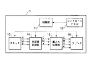
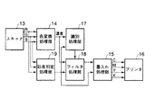
図1は画像処理装置1の概略的な構成を示している。画像処理装置1には、制御部11、コントロールパネル12、スキャナ13、色変換処理部14、墨入れ処理部15、プリンタ16が設けられている。
【0010】
制御部11は、図示しないCPU、ROM、RAMなどで構成されており、コントロールパネル12からの指示を受付け、スキャナ13、色変換処理部14、墨入れ処理部15、プリンタ16などを含む画像処理装置1全体を総括的に制御する。
【0011】
コントロールパネル12は、ユーザが制御部11に対して指示を与える、例えば、複写を開始するスタートキーなどの各種機能キーや数値キーなどの入力部、ユーザに必要な情報を報知するための表示部が設けられている。ユーザはコントロールパネル12の入力部を操作して複写の出力を2色の色で出力する2色カラーコピー及びその2色の色の指定を指示できるようになっている(印字色指定手段)。以下、2色カラーコピーの2色として、黒・赤の2色が指定された場合で説明する。
【0012】
スキャナ13は、図示しない所定位置に載置された原稿、又は図示しないADF(オート・ドキュメント・フィーダ)などで送られる複数枚の原稿から画像を読取り、R(赤)G(緑)B(青)色のRGB信号を生成し、色変換処理部14にRGB信号を入力する(入力手段)。なお、スキャナ13については一般的なものであるため、詳細な説明は省略する。
【0013】
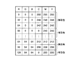
色変換処理部14は、スキャナから13入力されたRGB信号に色変換処理を施し、C(シアン)M(マゼンダ)Y(イエロー)各色のCMY信号を生成する。この色変換処理部14で行われる色変換処理は、LUT(ルック・アップ・テーブル)方式で行うものとする。その色変換LUTの一例は図2に示している。このように、色変換処理部14に設定する色変換LUTを図2に示す色変換パラメータを用いることで、スキャナ13より入力されたフルカラー信号であるRGB信号を、無彩色と有彩色の2つの状態の信号に変換することができる。この色変換パラメータは、例えば、RGB空間上の無彩色領域は“黒”と出力され、有彩色領域は“赤”と出力されるように設定する。従って、図2で示すパラメータを用いて出力される色状態は、次の2種類となる。すなわち、RGB信号が全て等量(無彩色)だと、C=M=Y(黒)となり、RGB信号が全て等量でない(有彩色)だと、C=0,M=Y(赤)となる。このように色変換処理により抽出された無彩色・有彩色をCMY信号の黒・赤として出力するのは、従来のフルカラーコピーの場合と同じパスを用いるためである。従って、通常のコピーの処理で用いる色変換LUTの色変換パラメータを切替えるだけで実現できる。これにより、色抽出のための画像処理回路を新たに追加する必要がなくハードウェアに対するコストを従来例と比較して低減することができる。また、RGB信号を、無彩色と有彩色と2つの状態の信号となるように変換しているので、3次元の色空間に対して次元数を落とした色空間に変換しているので高速な処理を実現できる。
【0014】
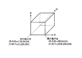
上述のように、色変換処理部14の色変換処理は、色変換LUTを用いた処理であるので、図3で示すように、RGB空間の格子点以外の領域については補間演算によりCMY信号を求める。このため、C≠0,C≠M,Yのようなシアン信号を持つことになる。このように無彩色、有彩色の境界付近で有彩色領域として抽出すべき色に対してシアン色が混入することは(C≠0、M=Yのような有彩色情報を置き換えた赤信号では無い。)、無彩色に近い色として抽出されることになる(なお、逆の可能性も有り得る)。従って、無彩色、有彩色の境界付近では色濁りが生じる場合がある。このように有彩色が無彩色として抽出され色濁りが生じる場合に対して、印字色の墨入れ処理(色割当手段)のパラメータを適正化することにより、色変換処理部14での抽出の難しい領域において、細かく切り分けを行うことで色濁りを低減することができる。この墨入れ処理部15のパラメータの適正化において、入力信号が黒・赤の2つの状態の信号に変換されているので、C信号とその他のM,Y信号との差の差分値を判定することで切り分けを容易に行うことができる。この差分値は、例えば、黒ならば差分値が小さくなり、赤ならば差分値が大きくなる。この差分値に基づく判定を行うために墨入れ処理部15の墨入れ処理は次のような処理を行う。
【0015】
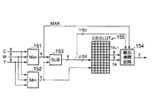
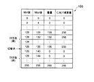
墨入れ処理部15は、変換された無彩色と有彩色との2状態の信号に対して、コントロールパネル12で指定された、例えば、黒・赤の2色の印字色に変換する処理を行う。図4は、この墨入れ処理部15の構成の一例を示す図である。図で示すように、色変換処理部14で処理されたC,M,Y信号が、最大値検出部151、最小値検出部152に入力される。最大値検出部(Max)151は、最大値(Max)を検出して減算器(SUB)153と線形補間回路154とに出力する。最小値検出部(Min)152は、最小値(Min)を検出して減算器(SUB)153と2次元ルック・アップ・テーブル(LUT)155とに出力する。減算器153は、入力される最大値(Max)と最小値(Min)との差分の上位6ビットを2次元LUT155に出力し、下位2ビットを線形補間回路154に出力する。2次元LUT155は、入力される減算器153からの上位6ビットの最大値(Max)と最小値(Min)との差分(Max−Min)と最小値検出部152からの最小値(Min)とに基づいてデータTA+1とTAとを線形補間回路154に出力する。線形補間回路154は、データTA+1とTAとの間を補間してそのデータを後段の処理部に出力する。このように構成された墨入れ処理部15は、CMY信号の最小値(Min値)、最大値(Max値)により2種類のLUTを参照して、墨量(K信号)とCMY減算量を決定するようになっている。例えば、コントロールパネル12により印字色として黒・赤の2色が指定されたとする。このように指定されると墨入れ処理により、C=M=Y(黒)であれば、黒1色処理を行う。具体的には、C=M=Yの場合であればMin値とMax値の差が小さくなるので黒1色処理を行う、すなわち、C,M,Y信号が“0”となるようにLUTを作成し、また、C=0、M=Y(赤)であれば、Min値が“0”近辺であるので、墨入れ処理をスルーするスルー処理とする、すなわち、C=K=0、M=YとなるようにLUTを作成する。このように、CMY信号の最小値と最大値を算出して、両者の値を元に墨量LUTとCMY減算量LUTを参照して墨入れを行う。この2種類のLUTの一例は図5に示している。この墨量のLUTとCMY減算のLUTはそれぞれ図5で示すような細かさを持つテーブル155となっている。このような細かさをLUT155が持つのは、墨量(K信号)と画像のざらつきに大きく相関があるからである。従って、このLUT155の細かさはフルカラー印刷を行う場合には必要なテーブルサイズである。このLUT155の細かさ(8512通りの組合せ)を利用してシアンと他色の色変換を細かく区別することができる。従って、3次元LUTで一括処理するよりも次元数が1つ少ないので、墨量LUT及びCMY減算LUTを細かく設定することができ、色濁りの少ない2色印字を実現することができる。
【0016】
プリンタ16は、墨入れ処理部15で処理されたCMYK信号に基づいて印字を行う。例えば、コントロールパネル12により黒・赤の2色が指定された2色カラーコピーであれば、黒・赤の2色の画像を出力し、2色カラーコピーを実現する。なお、プリンタ16ついては一般的なものであるため、詳細な説明は省略する。
【0017】
次にコントロールパネル12からの2色の指定が、黒・緑の2色のときの墨入れ処理部15における墨入れ処理を説明する。
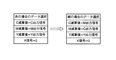
墨入れ処理部15に入力されたCMY信号から、Min値、Max値を算出し、墨量LUTとCMY減算LUTを参照する。CMY減算LUTはCMY各色に対してテーブルを持っており、CMY各色の減算した値を出力する。CMY各色の減算値を出力した後に、CMY信号の選択を行う。この選択はCMY減算値に対してプリンタ16で出力するためのCMY信号を選択するものである。つまり、CMY減算値を求めた時点では、プリンタへ出力する印字色は決定されていない。赤の場合ではCMY減算値をそのままCMY出力信号に割当てるのに対して、緑の場合ではM減算値をC出力信号に割当てC減算値をM出力信号に割当てる。すなわち、図6で示すように、赤の場合と緑の場合とで、C減算値の出力信号とM減算値の出力信号が入れ替わっている。このようにCMY各色の減算値に出力信号を割当てることにより、赤以外の色を印字することができる。また、減算LUTをCMY各色毎にもっているので、CMY各色の減算量を変化させることで、オレンジ等の色も印字できる。
【0018】
以上の構成により、画像処理装置1は2色カラーコピー用に新しく画像処理回路等のハードウェアを追加することなく、フルカラー用の画像処理を用いて2色カラーコピーが実現できるので、ハードウェアコストを安価にし、且つ印字色の変換精度を向上させることができ、色濁りを低減することができる。さらに、画像処理装置1は変換精度の調整も3次元から次元数を落として2次元としているため、3次元のRGB信号から直接印字色を算出するよりも、パラメータ調整を容易に行うことができる。
【0019】
なお、この実施の形態においては、色変換処理後の出力信号はCMY信号の3次元信号であるが、黒・赤の2状態の信号に変換されているので実質は2次元の信号である。
【0020】
また、色変換LUTによる色抽出を黒/赤、又は赤/緑の場合で説明したが、この組合わせに限るものではない。また、2状態の抽出を無彩色・有彩色の場合としたがそれ以外の組合せとしても良い。
【0021】
(第2の実施の形態)
次に、第2の実施の形態を説明する。前述した第1の実施の形態と同様な処理には同じ番号を付し、説明を省略する。
【0022】
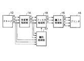
第2の実施の形態における画像処理の構成は、図7で示すように構成されている。スキャナ13で生成されたRGB信号及び色変換処理部14でRGB信号が色変換処理されたCMY信号が識別処理部(識別手段)17に入力される。また、識別処理部17からの識別信号がフィルタ処理部(フィルタ処理手段)18に入力される。また、フィルタ処理部18は、色変換処理部14と墨入れ処理部15との間に設けられ、色変換処理部14からのCMY信号が入力され、そのCMY信号にフィルタ処理を行ってから墨入れ処理部15へ出力される。
【0023】
識別処理部17は、色変換処理部14で変換された2つの状態の信号に対して、文字を示す信号であるかと写真を示す信号であるかを識別し、その識別結果である識別信号をフィルタ処理部18へ出力する。すなわち、識別処理部17は、画像が文字領域か写真領域であるかの識別を行う。この識別は、画像中からエッジ画素の抽出や矩形領域内の濃度変化を求め、文字領域であるか写真領域であるかを判定する。
【0024】
フィルタ処理部18は、色変換処理部14で変換された2つの状態の信号に対して、LPF(ローパスフィルタ)やHPF(ハイパスフィルタ)の処理を行う。このLPFやHPFの切替えは、識別処理部17からの識別信号に基づいてフィルタを切替える。文字を示す信号と識別された画素に対してはHPF処理を行い、写真を示す信号と識別された画素に対してはLPF処理を行う。
【0025】
次に、コントロールパネル12から黒・赤の2色が指定された2色カラーコピーが入力された場合で画像処理を説明する。色変換処理部14により、RGB空間上の無彩色領域を“黒”、有彩色領域であるその他の領域を“赤”の2状態の信号に変換され、識別処理部17及びフィルタ処理部18に信号が入力される。このとき、入力原稿に黒文字、赤文字、黄色文字が混在していたとすると、色変換処理部14では、このような原稿に対して有彩色である赤文字も、黄色文字も全て赤の信号に変換して識別処理部17及びフィルタ処理部18へ信号を出力する。しかし、黄色は赤に対して反射率が高いため色変換処理において、赤文字、黄色文字に対して有彩色である赤信号を生成しても濃度が異なってしまう。つまり、原稿上の黄色べたをスキャナ13で読込み、色変換処理で赤信号に割当てても赤べたの信号(C=0、M=Y=255)として出力されない。よって、従来例のように単にRGB信号の濃度変換を行って2色印字を行った場合では、原稿上の各色ごとに濃度差が生じることになる。このように同じ有彩色領域の文字であっても、色の違いにより濃度差が生じる問題を防ぐために、本実施の形態では識別処理部17とフィルタ処理部18のパラメータを有彩色・無彩色で切替えを行う。
【0026】
識別処理部17は、有彩色領域の信号である赤信号が入力された場合には、各色の色文字で濃度差が生じることを考慮して、濃度変化による文字識別の閾値を緩める必要がある。方や、無彩色領域の信号である黒信号については、RGBの反射率が低く色変換処理後の信号でも高い濃度信号で出力されるため、濃度変化による文字識別の閾値を狭くすることができる。このように2つの状態に変換された信号に対して独立にパラメータを設定することにより、文字画像の品質を向上させることができる(識別パラメータ設定手段)。
【0027】
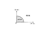
識別処理部17の識別パラメータの切替えは次のように実現する。識別処理部17に入力されたRGB信号から彩度を検出し、低彩度であれば無彩色用の識別パラメータを選択し、高彩度であれば有彩色用の識別パラメータを選択する。彩度の判定は、RGB信号より|R−G|と|G−B|を求めることにより得ることができる。低彩度・高彩度の判定は、図8に示すように、|R−G|軸と|G−B|軸の2次元平面上で、中心(原点)からの距離の大きさを示す彩度情報に基づいて判定する。原点からの距離が所定の値以下の場合に低彩度と判定し、所定の距離より大きい場合には高彩度と判定する。
【0028】
同様に、フィルタ処理部18のフィルタ処理においても2つの状態の信号に対して独立にフィルタパラメータを切替える。例えば、有彩色と判定された色文字は上述のように濃度が異なるので、フィルタ係数を高くする、すなわち、強調を強くすることにより文字の濃度を高くする。例えば、識別処理部17の識別処理で文字且つ有彩色と判定された信号に対しては、黄色の色文字であっても、M=Y=255と出力されるように強調処理を行う。また、無彩色と判定された黒信号については、文字画像でも高い濃度をもつため、フィルタの強調を有彩色の係数ほど高く設定しなくても、高濃度を再現することができる(フィルタパラメータ設定手段)。
【0029】
このように、識別処理部17の識別処理、フィルタ処理部18のフィルタ処理を行うときに、2つの状態に変換された信号に対して、それぞれ適正化させたパラメータを独立に設定することにより、文字画像の再現を向上させることができる。
以上の処理を行った信号に対して墨入れ処理部15で墨入れ処理を行うことで、印字色の2色を割当て、2色カラーコピーを実現する。
【0030】
以上に示した例では、色変換処理部14の色変換処理により、黒・赤の信号に変換した場合を示したが、その他の信号に変換しても良い。例えば、濃度信号と彩度信号の2つの状態に変換した場合について以下で説明する。
【0031】
この場合の画像処理の構成を図9に示している。図9に示すように、スキャナ13で生成されたRGB信号が色変換処理部14及び彩度判定処理部19に入力される。色変換処理部14によりスキャナ13から入力されたRGB信号に対して、濃度信号(モノクロ信号)を算出され、その信号が識別処理部17及びフィルタ処理部18へ出力される。識別処理部17により識別信号がフィルタ処理部18へ出力される。また、彩度判定処理部19により彩度情報が識別処理部17、フィルタ処理部18及び墨入れ処理部15へ出力される。フィルタ処理部18でフィルタ処理された信号は墨入れ処理部15へ出力される。墨入れ処理部15で生成されたCMYK信号はプリンタ16へ出力される。
【0032】
色変換処理部14におけるRGB信号から濃度信号への変換もLUTを用いて行うのでLUTのCMY信号は全て同じ値とする。また、彩度判定処理部19によりRGB信号から低彩度・高彩度を判定する。彩度は、RGB信号より、|R−G|と|G−B|とを求めることにより得ることができる。従って、低彩度、高彩度の判定は、図7を用いて説明した場合と同様の判定を行う。以上の処理によりRGB3次元の信号を濃度信号及び彩度信号の2次元信号に変換する。但し、変換された濃度信号は原稿上の黒べたに対して濃度=255となるように変換されるため、原稿上の有彩色のべたでは濃度≠255となり、印字出力でべた濃度を出力することができない。このような無彩色と有彩色での濃度差は、上述の実施の形態で説明した場合と同様であり、識別処理部17の識別処理とフィルタ処理部18のフィルタ処理により対処する。
【0033】
識別処理部17では、濃度信号と彩度信号の2次元信号に対して、濃度信号からエッジ検出、矩形領域内の濃度変化を算出し、信号が文字を示す信号であるか写真を示す信号であるかの文字写真の判定を行う。このとき、識別処理部17の識別パラメータは彩度判定処理部19から出力された彩度信号に基づいて切替える。具体的には、低彩度であれば、無彩色の画像であるので無彩色用の識別パラメータを選択する。また、高彩度であれば有彩色であるので有彩色用の識別パラメータを選択する。
【0034】
同じくフィルタ処理部18のフィルタ処理においても、入力された濃度信号に対して、彩度判定処理部19から出力された彩度信号に基づいてフィルタパラメータを切替える。つまり、識別信号で文字を示す信号であると判定され、かつ、彩度情報が高彩度(有彩色)を示す信号であれば、強調処理により255の値が出力されるファイルタパラメータを選択する。
【0035】
墨入れ処理部15においては、識別処理、フィルタ処理されたモノクロ信号に対して、彩度判定処理部19の彩度信号に基づいて、低彩度を示す信号であれば、K1色(K=モノクロ信号)で印字し、高彩度を示す信号であれば赤(C=K=0、M=Y=モノクロ信号)で印字する。
【0036】
以上のように、濃度信号、彩度信号と変換した2つの状態の信号に対してそれぞれ識別処理部17、フィルタ処理部18、墨入れ処理部15のパラメータを切替えて適正な処理を行うことで、文字画像の再現の向上を図ることができる。また、識別処理やフィルタ処理は、フルカラー印字の場合でも用いられる処理であり、パラメータを2色印字用で切替えるだけで実現できるので新規回路を追加する必要がなく安価に実現することができる。
【0037】
この第2の実施例では、色変換LUTによる色抽出を黒・赤で表現したが、その他の組合せでも良い。また、2状態の抽出を無彩色、有彩色としたがそれ以外の組合せでも良い。
【0038】
(第3の実施の形態)
次に、第3の実施の形態を説明する。前述した第2の実施の形態と同様な処理は同じ番号を付し、説明を省略する。この第3の実施の形態の画像処理の構成は、図7で説明した構成と同様である。
【0039】
この画像処理において、コントロールパネル12より2色カラーコピーの2色を同一の色で指定した場合には、単色カラーの再現になる。2色カラーコピーで単色カラーを実現するときには、従来単色カラーで再現されている濃度再現が求められる。つまり、ユーザにとっては、2色カラーコピーで単色カラーを出力した場合と、単色カラーモードで単色カラー出力した場合を区別させずに、どちらで出力しても同じ結果が得られることが望まれる。従って、2色印字の場合でも単色カラーを再現させることが必要である。このため、2色カラーコピーで単色カラーを実現するために、色変換処理部14の色変換処理で用いられるパラメータ、フィルタ処理部18のフィルタ処理で用いられるパラメータを次のように設定する。
【0040】
先ず、色変換処理部14では色変換LUTの値を単色コピー用のLUTを用いる。但し2色カラーコピーの動作(設定)であるため、有彩色範囲のシアン値を0にして設定する。以上にように設定することで、色変換処理後に出力される2つの状態に変換された信号は単色コピーと同じ濃度再現を持つ信号となる。また、同じ濃度再現の信号に対して、フィルタ処理部18で2つ状態の信号に同じフィルタ係数を用いる。これにより、フィルタ処理後の信号の濃度再現を同じにすることができる(濃度パラメータ設定手段)。
【0041】
その後墨入れ処理部15の墨入れ処理により、2つ状態の信号に対して指定された同一の印字色を割当てて出力する。以上のように色変換処理部14及びフィルタ処理部18のパラメータ設定することにより、2色の印字色に同一印字色を割当てても、単色カラーの場合と同じ濃度再現、すなわち、階調特性及び画質再現を実現できるので、良好な画像を得ることができる。
【0042】
上述の方法の他に、濃度信号、色差信号でも同じ効果を得ることも可能である。以下にその方法を説明する。画像処理の構成は上述の場合と同様であるため説明を省略する。色変換処理部14において、前記第2の実施の形態と同様にRGB信号を濃度信号に変換する。この異なる濃度再現の信号に対して識別処理部17及びフィルタ処理部18では濃度信号に対してパラメータの設定を同じものとする。そして、識別処理部17及びフィルタ処理部18で処理を行い、フィルタ処理部18のフィルタ処理により出力された濃度信号に対して、墨入れ処理部15で同色の印字色の割当てを行うようにしても上述の方法と同様な効果を奏することができる。
なお、この第3の実施例では2つの状態の抽出を無彩色、有彩色の状態としたがそれ以外の組合せでも良い。
【0043】
(第4の実施の形態)
次に、第4の実施の形態を説明する。前述した第1の実施の形態と同様な処理は同じ番号を付し、説明を省略する。
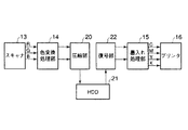
この第4の実施の形態の画像処理の構成を図10に示している。図10に示すように、画像処理の構成は、色変換処理部14と墨入れ処理部15との間に、圧縮手段である圧縮部20、保存手段であるHDD(ハード・ディスク・ドライブ)21及び復号手段である復号部22が設けられている。
【0044】
圧縮部20は、色変換処理部14により色変換処理され、2つの状態に変換された信号に対して圧縮処理を行う。この圧縮は、例えば、JPEG(ジョイント・フォトグラフィック・エクスパーツ・グループ)により圧縮を行う。JPEGの圧縮方法は、一般的な圧縮方法であるため説明は省略する。なお、圧縮部20の圧縮処理にJPEGを用いたが、他の圧縮処理を用いても良い。
【0045】
このように構成された画像処理の流れを説明する。上述のように色変換処理部14の色変換処理において、RGB信号を、例えば、無彩色(黒)、有彩色(赤)のように変換する。変換された2つの状態の信号それぞれに対して圧縮部20で圧縮を行い、圧縮された信号をHDD21に保存する。このように圧縮された信号をHDD21に保存するのは、図示しないADFにより複数枚原稿がセットされスキャナ13で連続して原稿を読取り、読取った大容量の信号を圧縮することにより容量を小さくしてからHDD21に保存するためである。また、HDD21に画像信号を保存することにより、スキャナ13の読取り動作と、プリンタ16の印字動作を独立させることができるので、画像処理装置1の操作性が向上する。但しスキャナ13が連続動作するため、スキャナ13の読取り速度や圧縮された画像信号サイズに応じてHDD21の転送レートを高速にする必要がある。そして、HDD21に保存された信号を読出し、復号部22で復号処理を行う。復号された信号に対して墨入れ処理部15の墨入れ処理により2色の印字色を割当てた後、プリンタ16で印字する。
【0046】
なお、信号の圧縮処理を行う処理位置として、3つの位置が考えられる。1つ目は、RGB信号で入力された時点で圧縮・復号を行う位置(色変換処理の前)である。2つ目は、2つ状態の信号に変換された状態で圧縮・復号を行う位置(色変換処理の後)である。3つ目は、印字色を割当てた後に圧縮・復号を行う位置(墨入れ処理後)である。
【0047】
1つ目の位置では入力信号がRGB信号であるため圧縮信号量が大きくなる。そのため、HDD21の転送レートの高速化や大容量の保存領域の確保が必要となる。また、3つ目の位置では2色の印字色が赤・緑のように両者がカラー色であると、2つの状態の信号をともにカラー画像として圧縮を行わなければならない。そのため、1つ目の位置の場合と同様に圧縮信号量が大きくなるので、HDD21の転送レートの高速化及び大容量の保存領域の確保が必要となる。これに対して2つ目の位置では、無彩色(黒)・有彩色(赤)のように2つの状態の信号になっているため、無彩色の信号は色信号を削除できる。そのため、圧縮信号量を削減することができる。以上のように、2つの状態に変換された信号で圧縮・復号を行うことで信号量を削減することができ、HDD21の転送レートを高速化させること無く、且つ大容量の保存領域を確保しなくても良くなる。従って、HDD21に対するハードウェアコストを安価なものとすることができる。
【0048】
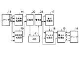
以上の説明では、圧縮部20に入力される2つの状態の信号を黒・赤としたが、輝度・彩度の状態で入力しても同様に圧縮信号量を削減することができる。以下に輝度・彩度の2つの状態の信号に変換される場合の画像処理の構成を図11に示している。図11に示すように、色変換処理部14及び彩度判定処理部19と識別処理部17及びフィルタ処理部18との間に、圧縮部20、HDD21及び復号部22が設けられている。
【0049】
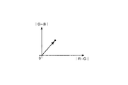
このように構成された画像処理の流れを説明する。色変換処理部14において入力されたRGB信号に対して色変換処理が行われ、濃度信号(モノクロ信号)を算出する。また、彩度判定処理部19の彩度判定処理によりRGB信号から低彩度・高彩度を検出する。この彩度の検出はRGB信号より、|R−G|と|G−B|とを求めることにより得ることができる。図12で示すように、|R−G|軸と|G−B|軸の2次元平面上で、中心(原点)からの距離の大きさを示す彩度信号を検出する。この彩度信号に基づいて、例えば、原点からの距離が所定の値以下の場合に低彩度と判定し、所定の距離より大きい場合には高彩度と判定することができる。以上のように算出された濃度信号・彩度信号を圧縮部20に入力する。この圧縮部20におけるJPEG圧縮は、Y(輝度)Cb(色差)Cr(色差)の信号で圧縮を行いHDD21に圧縮された信号を保存する。この実施の形態では、濃度信号をY(輝度)信号に、彩度信号をCb(色差)信号に割当てる。Cr(色差)信号には信号を割当てないのでCr信号に対応する圧縮部20は必要ない。このように濃度信号及び彩度信号の2次元信号に変換してJPEG圧縮を行うことにより、色差信号の1つが不要となり、圧縮信号量の削減とHDD21の規模を縮小できる。そして、HDD21に保存された圧縮された圧縮信号を復号部22で復号処理を行い、復号された濃度信号・彩度信号を識別処理部17及びフィルタ処理部18へ出力する。この後の処理については図6を参照して説明した処理と同様なので省略する。
【0050】
以上の構成により、濃度信号及び彩度信号の2つの状態で圧縮を行うことで、HDD21に保存される圧縮信号量を削減することができる。よってHDD21の転送レートを高速化すること無く、且つ大容量の保存領域を確保しなくても良いので、ハードウェアに対するコストを安価なものとすることができる。
【0051】
また、上記各実施の形態は本発明を2色カラーコピーに適用した場合で説明したが、必ずしもこれに限るものではなく、ネットワーク機能が設けられている画像処理装置においては、ネットワークスキャンを行う場合にも本発明を応用することができる。
【0052】
なお、この発明は、上記実施の形態そのままに限定されるものではなく、実施段階ではその要旨を逸脱しない範囲で構成要素を変形して具体化できる。また、上記実施形態に開示されている複数の構成要素の適宜な組合わせにより種々の発明を変形でき、また、実施形態に示される全構成要素から幾つかの構成要素を削除してもよい。更に、異なる実施形態に亘る構成要素を適宜組み合わせてもよい。
【0053】
【発明の効果】
以上説明したように本発明によれば、2色印字を行うときに色濁りを低減すると共にコストの低減を図ることができる画像処理装置、画像処理方法及び画像形成装置を提供できる。
【図面の簡単な説明】
【図1】 本発明の第1の実施の形態における画像処理装置の概略的な構成を示す図。
【図2】 同実施の形態における色変換処理に用いるLUTを示す図。
【図3】 同実施の形態における無彩色・有彩色の境界を示す図。
【図4】 同実施の形態における墨入れ処理部の構成例を示す図。
【図5】 同実施の形態における墨入れ処理に用いるLUTを示す図。
【図6】 同実施の形態におけるCMY減算値の出力信号の割当てを示す図。
【図7】 本発明の第2の実施の形態における画像処理の構成を示す図。
【図8】 同実施の形態における彩度判定のための2次元平面を概念的に示す図。
【図9】 同実施の形態における画像処理の他の構成を示す図。
【図10】 本発明の第4の実施の形態における画像処理の構成を示す図。
【図11】 同実施の形態における画像処理の他の構成を示す図。
【図12】 同実施の形態における彩度情報を求めるための2次元平面を概念的に示す図。
【符号の説明】
1…画像処理装置,12…コントロールパネル,13…スキャナ,14…色変換処理部,15…墨入れ処理部,16…プリンタ,17…識別処理部,18…フィルタ処理部,19…彩度判定処理部,20…圧縮部,21…HDD,22…復号部[0001]
BACKGROUND OF THE INVENTION
The present invention relates to an image processing apparatus that performs printing in two designated colors on a color input image signal., Image processing method and image forming apparatusAbout.
[0002]
[Prior art]
In recent years, there has been proposed an image processing apparatus such as a color digital copying machine that reads a document in two colors designated by a user using a control panel, for example, black and red. As such image processing when printing with two colors, for example, a method of directly converting input RGB signals into black / red signals as output colors by matrix calculation has been proposed. When the black and red CMYK signals are directly calculated from the RGB signals by the matrix operation in this way, unnecessary color C and K signals are mixed with the obtained red signals, causing color turbidity, or the black signals. Unnecessary color C, M, and Y signals are mixed, resulting in color turbidity. The cause of such turbidity is that it is difficult to obtain a matrix coefficient that reproduces two colors of red and black with a CMYK signal for a signal having 256 gradations of each RGB color and that does not cause gradation inversion. Is the cause.
[0003]
In order to avoid the occurrence of such color turbidity, density conversion is performed on RGB data input from the scanner to generate a monochrome signal, and color conversion processing from RGB signals to CMY signals is performed, and then hue determination processing is performed. It determines whether to print in black or red for each pixel by hue and saturation determination, and the density signal converted by density conversion for the determined print color A method of performing printing has been proposed (see, for example, Patent Document 1).
[0004]
[Patent Document 1]
JP-A-8-84268
[0005]
[Problems to be solved by the invention]
However, in the proposed method, since it is necessary to provide a circuit for determining hue and saturation, extra cost is generated for the circuit. Further, since the signal is converted into black and red and printed as it is, it is impossible to switch the processing to a character area or a photographic area in the image.
[0006]
The present invention has been made in view of the above circumstances, and its object is to provide a process for reducing the number of dimensions of an input three-dimensional image signal and a process for reproducing two specified print colors. Image processing apparatus capable of reducing color turbidity and reducing cost when performing two-color printing, Image processing method and image forming apparatusIs to provide.
[0007]
[Means for Solving the Problems]
The present inventionAn input means for inputting a color image signal, a print color designating means for designating a print color, and the color image signal inputted by the input means indicate any one of the CMY components with the same value as the print color. An image processing apparatus comprising: conversion means for converting into a multi-value signal; and inking processing means for performing inking processing on the converted multi-value signal and outputting a multi-valued CMYK signal.
[0008]
DETAILED DESCRIPTION OF THE INVENTION
Embodiments of the present invention will be described below with reference to the drawings.
[0009]
(First embodiment)
FIG. 1 shows a schematic configuration of the
[0010]
The
[0011]
The
[0012]
The
[0013]
The color
[0014]
As described above, since the color conversion process of the color
[0015]
The inking
[0016]
The
[0017]
Next, the inking process in the
The Min value and the Max value are calculated from the CMY signal input to the
[0018]
With the above configuration, the
[0019]
In this embodiment, the output signal after the color conversion process is a three-dimensional signal of a CMY signal, but is actually a two-dimensional signal because it is converted into a black / red two-state signal.
[0020]
Further, although the color extraction by the color conversion LUT has been described in the case of black / red or red / green, it is not limited to this combination. In addition, although the extraction of the two states is the case of an achromatic color and a chromatic color, other combinations may be used.
[0021]
(Second Embodiment)
Next, a second embodiment will be described. The same processes as those in the first embodiment described above are denoted by the same reference numerals, and description thereof is omitted.
[0022]
The configuration of the image processing in the second embodiment is configured as shown in FIG. The RGB signal generated by the
[0023]
The
[0024]
The
[0025]
Next, image processing will be described when a two-color copy in which two colors of black and red are designated is input from the
[0026]
When the red signal that is the signal of the chromatic color region is input, the
[0027]
Switching of the identification parameter of the
[0028]
Similarly, also in the filter processing of the
[0029]
In this way, by performing the identification processing of the
The
[0030]
In the example shown above, the case where the signal is converted into the black / red signal by the color conversion processing of the color
[0031]
FIG. 9 shows the configuration of image processing in this case. As shown in FIG. 9, the RGB signal generated by the
[0032]
Since the conversion from the RGB signal to the density signal in the color
[0033]
The
[0034]
Similarly, in the filter processing of the
[0035]
In the
[0036]
As described above, by appropriately changing the parameters of the
[0037]
In the second embodiment, the color extraction by the color conversion LUT is expressed in black and red, but other combinations may be used. In addition, although the extraction of the two states is achromatic and chromatic, other combinations may be used.
[0038]
(Third embodiment)
Next, a third embodiment will be described. The same processes as those in the second embodiment described above are denoted by the same reference numerals, and description thereof is omitted. The configuration of the image processing of the third embodiment is the same as the configuration described in FIG.
[0039]
In this image processing, when two colors of a two-color copy are designated by the same color from the
[0040]
First, the color
[0041]
Thereafter, the inking process of the inking
[0042]
In addition to the method described above, the same effect can be obtained with a density signal and a color difference signal. The method will be described below. Since the configuration of the image processing is the same as that described above, description thereof is omitted. The color
In the third embodiment, the two states are extracted as achromatic and chromatic, but other combinations may be used.
[0043]
(Fourth embodiment)
Next, a fourth embodiment will be described. The same processes as those in the first embodiment described above are denoted by the same reference numerals, and the description thereof is omitted.
FIG. 10 shows the configuration of image processing according to the fourth embodiment. As shown in FIG. 10, the configuration of the image processing is between a color
[0044]
The
[0045]
A flow of image processing configured as described above will be described. As described above, in the color conversion processing of the color
[0046]
Note that three positions are conceivable as processing positions for signal compression processing. The first is a position (before color conversion processing) where compression / decoding is performed when RGB signals are input. The second is a position (after color conversion processing) where compression / decoding is performed in a state converted into a two-state signal. The third is a position (after inking process) where compression / decoding is performed after assigning a print color.
[0047]
Since the input signal is an RGB signal at the first position, the amount of compressed signal is large. For this reason, it is necessary to increase the transfer rate of the
[0048]
In the above description, the signals in the two states input to the
[0049]
A flow of image processing configured as described above will be described. Color conversion processing is performed on the RGB signal input in the color
[0050]
With the above configuration, the compression signal amount stored in the
[0051]
In the above embodiments, the present invention has been described in the case where the present invention is applied to a two-color copy. However, the present invention is not limited to this. In an image processing apparatus provided with a network function, a network scan is performed. The present invention can also be applied to.
[0052]
Note that the present invention is not limited to the above-described embodiment as it is, and can be embodied by modifying the constituent elements without departing from the scope of the invention in the implementation stage. In addition, various inventions can be modified by appropriately combining a plurality of constituent elements disclosed in the above embodiment, and some constituent elements may be deleted from all the constituent elements shown in the embodiment. Furthermore, you may combine the component covering different embodiment suitably.
[0053]
【The invention's effect】
As described above, according to the present invention, an image processing apparatus capable of reducing color turbidity and reducing costs when performing two-color printing., Image processing method and image forming apparatusCan provide.
[Brief description of the drawings]
FIG. 1 is a diagram showing a schematic configuration of an image processing apparatus according to a first embodiment of the present invention.
FIG. 2 is a diagram showing an LUT used for color conversion processing in the embodiment.
FIG. 3 is a diagram showing a boundary between an achromatic color and a chromatic color in the embodiment.
FIG. 4 is a diagram showing a configuration example of an inking process unit in the embodiment.
FIG. 5 is a diagram showing an LUT used for inking processing in the embodiment.
FIG. 6 is a diagram showing assignment of output signals of CMY subtraction values in the same embodiment;
FIG. 7 is a diagram showing a configuration of image processing according to the second embodiment of the present invention.
FIG. 8 is a diagram conceptually showing a two-dimensional plane for determining saturation in the embodiment.
FIG. 9 is a diagram showing another configuration of image processing in the embodiment.
FIG. 10 is a diagram showing a configuration of image processing according to a fourth embodiment of the present invention.
FIG. 11 is a diagram showing another configuration of image processing in the embodiment.
FIG. 12 is a diagram conceptually showing a two-dimensional plane for obtaining saturation information in the embodiment.
[Explanation of symbols]
DESCRIPTION OF
Claims (13)
印字色を指定する印字色指定手段と、
前記入力手段により入力されたカラー画像信号をCMY各成分の内いずれか2つを同じ値として前記印字色を示す多値信号に変換する変換手段と、
変換された前記多値信号に墨入れ処理を施して多値CMYK信号を出力する墨入れ処理手段と
を具備したことを特徴とする画像処理装置。An input means for inputting a color image signal;
And print color specifying means for specifying the mark character color,
Conversion means for converting the color image signal input by the input means into a multi-value signal indicating the print color with any two of the CMY components as the same value ;
The image processing apparatus being characterized in that; and a black generation processing means for outputting the multi-level CMYK signal by performing inking process on the converted the multi-level signal.
前記識別手段で用いるパラメータを、前記多値信号に対してそれぞれ独立に設定する識別パラメータ設定手段と
をさらに具備したことを特徴とする請求項1記載の画像処理装置。Identifying means for identifying whether the multi-value signal is a signal indicating a character or a signal indicating a photograph;
The image processing apparatus according to claim 1, further comprising: an identification parameter setting unit that sets parameters used in the identification unit independently for the multilevel signal.
前記フィルタ処理手段で用いるパラメータを、前記多値信号に対してそれぞれ独立に設定するフィルタパラメータ設定手段と
をさらに具備したことを特徴とする請求項1記載の画像処理装置。Filter processing means for performing filter processing on the multilevel signal;
The image processing apparatus according to claim 1, further comprising: a filter parameter setting unit that sets parameters used in the filter processing unit independently for each of the multilevel signals.
この圧縮手段により圧縮された前記多値信号を保存する保存手段と、
この保存手段に保存された圧縮された前記多値信号の復号処理を行う復号処理手段と
をさらに具備したことを特徴とする請求項1記載の画像処理装置。Compression means for independently compressing the multilevel signal;
Storage means for storing the multilevel signal compressed by the compression means;
The image processing apparatus according to claim 1, further comprising: a decoding processing unit that performs a decoding process on the compressed multilevel signal stored in the storage unit.
入力手段により入力されたカラー画像信号をCMY各成分の内いずれか2つを同じ値として前記印字色を示す多値信号に変換し、
その多値信号に墨入れ処理を施して多値CMYK信号を出力すること
を特徴とする画像処理方法。Specifies a mark character color,
The color image signal input by the input means is converted into a multi-value signal indicating the print color with any two of the CMY components having the same value ,
Image processing method and outputting the multi-level CMYK signal by performing inking process to the multi-level signal.
入力手段により入力されたカラー画像信号をCMY各成分の内いずれか2つを同じ値として前記印字色を示す多値信号に変換し、
その多値信号に対して文字を示す信号であるか写真を示す信号であるかの識別を行い、
前記多値信号に対してそれぞれ独立に識別処理で用いるパラメータの設定を行い、
識別処理を行い、
この処理された多値信号に墨入れ処理を施して多値CMYK信号を出力すること
を特徴とする画像処理方法。Specifies a mark character color,
The color image signal input by the input means is converted into a multi-value signal indicating the print color with any two of the CMY components having the same value ,
Identify whether the multi-level signal is a signal indicating characters or a signal indicating a photograph,
Set the parameters used in the identification process independently for each of the multilevel signals,
There line the identification process,
An image processing method comprising: applying a blacking process to the processed multilevel signal and outputting a multilevel CMYK signal .
入力手段により入力されたカラー画像信号をCMY各成分の内いずれか2つを同じ値として前記印字色を示す多値信号に変換し、
その多値信号に対して文字を示す信号であるか写真を示す信号であるかの識別を行い、
前記多値信号に対してそれぞれ独立にフィルタ処理で用いるパラメータの設定を行い、
フィルタ処理を行い、
この処理された多値信号に墨入れ処理を施して多値CMYK信号を出力すること
を特徴とする画像処理方法。Specifies a mark character color,
The color image signal input by the input means is converted into a multi-value signal indicating the print color with any two of the CMY components having the same value ,
Identify whether the multi-level signal is a signal indicating characters or a signal indicating a photograph,
Set the parameters used in the filter processing independently for each of the multilevel signals,
There line filtering,
An image processing method comprising: applying a blacking process to the processed multilevel signal and outputting a multilevel CMYK signal .
入力手段により入力されたカラー画像信号をCMY各成分の内いずれか2つを同じ値として前記印字色を示す多値信号に変換し、
その多値信号に対してそれぞれ独立して圧縮処理を行い保存し、その保存された圧縮処理された多値信号を復号処理し、
その復号処理された多値信号に墨入れ処理を施して多値CMYK信号を出力すること
を特徴とする画像処理方法。Specifies a mark character color,
The color image signal input by the input means is converted into a multi-value signal indicating the print color with any two of the CMY components having the same value ,
Each multilevel signal is compressed and stored independently, the stored compressed multilevel signal is decoded,
Image processing method and outputting the multi-level CMYK signal by performing inking process to the decoded processed multi-level signal.
印字色を指定する印字色指定手段と、 A print color specifying means for specifying a print color;
前記入力手段により入力されたカラー画像信号をCMY各成分の内いずれか2つを同じ値として前記印字色を示す多値信号に変換する変換手段と、 Conversion means for converting the color image signal input by the input means into a multi-value signal indicating the print color with any two of the CMY components as the same value;
変換された前記多値信号に墨入れ処理を施して多値CMYK信号を出力する墨入れ処理手段と、 An inking process means for applying an inking process to the converted multilevel signal and outputting a multilevel CMYK signal;
前記多値CMYK信号に基づいて印字を行うプリンタ手段と Printer means for performing printing based on the multilevel CMYK signal;
を具備したことを特徴とする画像処理装置。 An image processing apparatus comprising:
Priority Applications (2)
| Application Number | Priority Date | Filing Date | Title |
|---|---|---|---|
| JP2003150851A JP4217536B2 (en) | 2003-05-28 | 2003-05-28 | Image processing apparatus, image processing method, and image forming apparatus |
| US10/694,981 US20040239969A1 (en) | 2003-05-28 | 2003-10-29 | Image processing apparatus and method |
Applications Claiming Priority (1)
| Application Number | Priority Date | Filing Date | Title |
|---|---|---|---|
| JP2003150851A JP4217536B2 (en) | 2003-05-28 | 2003-05-28 | Image processing apparatus, image processing method, and image forming apparatus |
Publications (2)
| Publication Number | Publication Date |
|---|---|
| JP2004356853A JP2004356853A (en) | 2004-12-16 |
| JP4217536B2 true JP4217536B2 (en) | 2009-02-04 |
Family
ID=33447740
Family Applications (1)
| Application Number | Title | Priority Date | Filing Date |
|---|---|---|---|
| JP2003150851A Expired - Lifetime JP4217536B2 (en) | 2003-05-28 | 2003-05-28 | Image processing apparatus, image processing method, and image forming apparatus |
Country Status (2)
| Country | Link |
|---|---|
| US (1) | US20040239969A1 (en) |
| JP (1) | JP4217536B2 (en) |
Cited By (1)
| Publication number | Priority date | Publication date | Assignee | Title |
|---|---|---|---|---|
| EP2530926A2 (en) | 2011-05-30 | 2012-12-05 | Ricoh Company, Ltd. | Image processing apparatus and color conversion table generating method |
Families Citing this family (10)
| Publication number | Priority date | Publication date | Assignee | Title |
|---|---|---|---|---|
| US7990573B2 (en) * | 2004-03-17 | 2011-08-02 | Xerox Corporation | User-adjustable mechanism for extracting full color information from two-color ink definitions |
| KR100698331B1 (en) * | 2005-01-28 | 2007-03-23 | 삼성전자주식회사 | Image display device and its color adjustment method |
| JP2007049494A (en) * | 2005-08-10 | 2007-02-22 | Konica Minolta Business Technologies Inc | Creation method for color transformation table, image processing apparatus, image processing method, image forming apparatus, and record medium |
| US20070253039A1 (en) * | 2006-04-28 | 2007-11-01 | Kabushiki Kaisha Toshiba | Image processing apparatus |
| US20070285685A1 (en) * | 2006-06-12 | 2007-12-13 | Kabushiki Kaisha Toshiba | Image forming apparatus and image forming method |
| JP5678584B2 (en) * | 2009-12-16 | 2015-03-04 | 株式会社リコー | Image processing apparatus, image processing method, and program |
| JP5487988B2 (en) * | 2010-01-18 | 2014-05-14 | セイコーエプソン株式会社 | Image processing apparatus, image processing method, and program thereof |
| JP5598146B2 (en) * | 2010-08-05 | 2014-10-01 | セイコーエプソン株式会社 | Print control program and print control apparatus |
| KR101783259B1 (en) * | 2010-12-31 | 2017-10-10 | 삼성디스플레이 주식회사 | Method for compensating data, compensating apparatus for performing the method and display device having the compensating apparatus |
| JP2023013472A (en) * | 2021-07-16 | 2023-01-26 | セイコーエプソン株式会社 | printer |
Family Cites Families (6)
| Publication number | Priority date | Publication date | Assignee | Title |
|---|---|---|---|---|
| JPH10336466A (en) * | 1997-05-29 | 1998-12-18 | Toshiba Corp | Image forming apparatus and image processing apparatus |
| JP4083327B2 (en) * | 1998-12-22 | 2008-04-30 | 株式会社東芝 | Color image processing device |
| JP4191832B2 (en) * | 1998-12-22 | 2008-12-03 | 株式会社東芝 | Color conversion correspondence table construction method and color conversion device |
| JP4256547B2 (en) * | 1999-08-31 | 2009-04-22 | 東芝テック株式会社 | Color image processing device |
| US7023582B2 (en) * | 2001-08-21 | 2006-04-04 | Kabushiki Kaisha Toshiba | Image processing apparatus |
| US7158271B2 (en) * | 2002-05-13 | 2007-01-02 | Kabushiki Kaisha Toshiba | Image processing apparatus |
-
2003
- 2003-05-28 JP JP2003150851A patent/JP4217536B2/en not_active Expired - Lifetime
- 2003-10-29 US US10/694,981 patent/US20040239969A1/en not_active Abandoned
Cited By (1)
| Publication number | Priority date | Publication date | Assignee | Title |
|---|---|---|---|---|
| EP2530926A2 (en) | 2011-05-30 | 2012-12-05 | Ricoh Company, Ltd. | Image processing apparatus and color conversion table generating method |
Also Published As
| Publication number | Publication date |
|---|---|
| US20040239969A1 (en) | 2004-12-02 |
| JP2004356853A (en) | 2004-12-16 |
Similar Documents
| Publication | Publication Date | Title |
|---|---|---|
| JP3436828B2 (en) | Image processing device | |
| US7327874B2 (en) | Method of and apparatus for image processing apparatus, and computer product | |
| US7535595B2 (en) | Image processing apparatus and method, and computer program product | |
| JP2006237856A (en) | Image processing apparatus, image processing method, program for causing computer to execute the method, and recording medium | |
| JP3964297B2 (en) | Image processing apparatus, image processing method, and program executed by computer | |
| JP4217536B2 (en) | Image processing apparatus, image processing method, and image forming apparatus | |
| US8035870B2 (en) | Image processing apparatus and image processing method | |
| JP2004289819A (en) | Image forming apparatus and image forming method | |
| JP2906974B2 (en) | Color image processing method and apparatus | |
| JP2021027434A (en) | Image processing device | |
| JP3929030B2 (en) | Image processing device | |
| JP4155634B2 (en) | Image forming apparatus, image forming system, and computer-readable recording medium | |
| JP2004187119A (en) | Image processing apparatus, image processing system, and image processing method | |
| JP3772610B2 (en) | Image forming apparatus and control method thereof | |
| JP2002218271A (en) | Image processing apparatus, image forming apparatus, and image processing method | |
| JP2002077647A (en) | Image processing device | |
| JP4847092B2 (en) | Image processing apparatus and toner saving method | |
| JP4409871B2 (en) | Color space conversion apparatus and image forming apparatus | |
| JP3767210B2 (en) | Document type determination device and image processing device | |
| JP3988970B2 (en) | Image processing apparatus, image processing method, and storage medium | |
| JP3615308B2 (en) | Image processing apparatus and method | |
| JP4154163B2 (en) | Image processing apparatus, image processing method, and color copying machine | |
| JP2001352456A (en) | Image processing method, image processing apparatus, and image forming apparatus having the same | |
| JP3581756B2 (en) | Image processing device | |
| JP4101741B2 (en) | Image processing apparatus, image forming apparatus, image processing method, image processing program, and recording medium |
Legal Events
| Date | Code | Title | Description |
|---|---|---|---|
| A621 | Written request for application examination |
Free format text: JAPANESE INTERMEDIATE CODE: A621 Effective date: 20060413 |
|
| A977 | Report on retrieval |
Free format text: JAPANESE INTERMEDIATE CODE: A971007 Effective date: 20080331 |
|
| A131 | Notification of reasons for refusal |
Free format text: JAPANESE INTERMEDIATE CODE: A131 Effective date: 20080805 |
|
| A521 | Request for written amendment filed |
Free format text: JAPANESE INTERMEDIATE CODE: A523 Effective date: 20081003 |
|
| TRDD | Decision of grant or rejection written | ||
| A01 | Written decision to grant a patent or to grant a registration (utility model) |
Free format text: JAPANESE INTERMEDIATE CODE: A01 Effective date: 20081104 |
|
| A01 | Written decision to grant a patent or to grant a registration (utility model) |
Free format text: JAPANESE INTERMEDIATE CODE: A01 |
|
| A61 | First payment of annual fees (during grant procedure) |
Free format text: JAPANESE INTERMEDIATE CODE: A61 Effective date: 20081110 |
|
| R150 | Certificate of patent or registration of utility model |
Ref document number: 4217536 Country of ref document: JP Free format text: JAPANESE INTERMEDIATE CODE: R150 Free format text: JAPANESE INTERMEDIATE CODE: R150 |
|
| FPAY | Renewal fee payment (event date is renewal date of database) |
Free format text: PAYMENT UNTIL: 20111114 Year of fee payment: 3 |
|
| FPAY | Renewal fee payment (event date is renewal date of database) |
Free format text: PAYMENT UNTIL: 20111114 Year of fee payment: 3 |
|
| FPAY | Renewal fee payment (event date is renewal date of database) |
Free format text: PAYMENT UNTIL: 20121114 Year of fee payment: 4 |
|
| FPAY | Renewal fee payment (event date is renewal date of database) |
Free format text: PAYMENT UNTIL: 20131114 Year of fee payment: 5 |
|
| EXPY | Cancellation because of completion of term |