JP4215589B2 - Induction heating cooker - Google Patents
Induction heating cooker Download PDFInfo
- Publication number
- JP4215589B2 JP4215589B2 JP2003282404A JP2003282404A JP4215589B2 JP 4215589 B2 JP4215589 B2 JP 4215589B2 JP 2003282404 A JP2003282404 A JP 2003282404A JP 2003282404 A JP2003282404 A JP 2003282404A JP 4215589 B2 JP4215589 B2 JP 4215589B2
- Authority
- JP
- Japan
- Prior art keywords
- heating coil
- heating
- magnetic
- magnetic material
- pan
- Prior art date
- Legal status (The legal status is an assumption and is not a legal conclusion. Google has not performed a legal analysis and makes no representation as to the accuracy of the status listed.)
- Expired - Lifetime
Links
Images

Landscapes
- Induction Heating Cooking Devices (AREA)
Description
本発明は、アルミニウムや銅等の非磁性金属よりなる調理鍋を連続加熱できる加熱コイルを備えた誘導加熱調理器に関するものである。 The present invention relates to an induction heating cooker provided with a heating coil capable of continuously heating a cooking pan made of a nonmagnetic metal such as aluminum or copper.
従来のこの種誘導加熱調理器の代表的なものとして、特許文献1(特開2003−17232号公報)に示すものがある。 A typical example of this conventional induction heating cooker is shown in Patent Document 1 (Japanese Patent Laid-Open No. 2003-17232).
このものは、本体外面に吸気部と排気部とを備え、本体内に複数の加熱コイルと、前記吸気部と通気路で繋がった冷却ファンと、前記加熱コイルをそれぞれ駆動する回路ユニットとを備え、前記複数の加熱コイルのうち前記冷却ファンに近い側に、アルミニウム製鍋を連続加熱できる加熱コイルを配置したものである。 This device includes an air intake portion and an exhaust portion on the outer surface of the main body, and includes a plurality of heating coils in the main body, a cooling fan connected to the air intake portion and an air passage, and a circuit unit that drives each of the heating coils. The heating coil capable of continuously heating the aluminum pan is disposed on the side close to the cooling fan among the plurality of heating coils.
また、本体外面に吸気部と排気部とを備え、本体内に複数の加熱コイルと、前記吸気部と通気路で繋がった冷却ファンと、前記加熱コイルをそれぞれ駆動する回路ユニットと、ロースターとを備え、前記ロースターから遠い側に、アルミニウム製鍋を連続加熱できる加熱コイルを配置したものも示されている。 The main body has an intake section and an exhaust section on the outer surface, a plurality of heating coils in the main body, a cooling fan connected to the intake section with a ventilation path, a circuit unit for driving the heating coils, and a roaster, respectively. It is also shown that a heating coil capable of continuously heating an aluminum pan is disposed on the side far from the roaster.
上記従来の構成では、安価で、すでに一般家庭に非常に多く普及している非磁性体のアルミニウム製鍋を使用する場合、その加熱部位が冷却ファンに近い側か又はロースターから遠い側に限定されてしまう。 In the above conventional configuration, when using a non-magnetic aluminum pan that is inexpensive and already widely used in ordinary households, the heating part is limited to the side near the cooling fan or the side far from the roaster. End up.
また、複数の調理物を同時に連続して加熱する場合には、一方に安価なアルミニウム製鍋を使用できても、他方では高価で重い磁性体よりなる鉄製鍋やホーロー製鍋を使用しなければならない。 In addition, when heating multiple cooked foods simultaneously, even if you can use an inexpensive aluminum pan on one side, you must use an iron pan or enamel pan made of expensive and heavy magnetic material on the other side. Don't be.
このため使用時の鍋材質に制約がある。また、ロースターから遠い側にアルミニウム製鍋を連続加熱できる加熱コイルがあるため、常時アルミニウム製鍋を使用する側が決まってしまい、誘導加熱調理器の設置場所にも制約ができてしまう。これらの理由により誘導加熱調理器自体の普及の妨げともなっていた。 For this reason, there are restrictions on the pan material at the time of use. Moreover, since there is a heating coil that can continuously heat the aluminum pan on the side far from the roaster, the side on which the aluminum pan is always used is determined, and the installation location of the induction heating cooker can be restricted. For these reasons, it has been a hindrance to the spread of induction heating cookers themselves.
本発明は、上記の課題を解決するためになされたものであり、加熱に際して使用できる鍋材質の制約や調理器本体の設置場所の制約を排除し、使用者が安価な鍋を自由に使用できるようにすることにより、さらなる誘導加熱調理器自体の普及に貢献できるようにしたものである。 The present invention has been made in order to solve the above-mentioned problems, eliminates restrictions on the pot material that can be used for heating and restrictions on the location of the cooking device body, and allows the user to freely use an inexpensive pot. By doing so, it is possible to contribute to the spread of further induction heating cookers themselves.
本発明の解決手段は、本体の上面に被加熱物を載置する絶縁板を配置し、この絶縁板の下方の前記本体内に加熱コイルA、加熱コイルBと、この加熱コイルA、加熱コイルBに対して被加熱物が磁性体である鉄製鍋か非磁性体であるアルミニウム製鍋かを判別し、その判別結果に基づいて夫々磁性体である鉄製鍋用と非磁性体であるアルミニウム製鍋用の高周波電力を供給するインバータ回路を搭載した出力制御基板を配置し、前記加熱コイルA、加熱コイルBは、いずれも磁性体である鉄製鍋と非磁性体であるアルミニウム製鍋を加熱できるものとし、前記出力制御基板は、前記加熱コイルA、加熱コイルBに対して前記被加熱物が磁性体である鉄製鍋か非磁性体であるアルミニウム製鍋かを電流値にて判別し、前記加熱コイルA、加熱コイルBに対応した前記絶縁板上に磁性体である鉄製鍋、非磁性体であるアルミニウム製鍋が載置された場合には、該被加熱物に磁性体である鉄製鍋及び非磁性体であるアルミニウム製鍋用の異なる周波数の高周波電力を供給するように制御し、前記加熱コイルA、加熱コイルBに対応した前記絶縁板上に非磁性体であるアルミニウム製鍋が載置された場合には、該アルミニウム製鍋に非磁性体用の周波数である約60KHz以上の高周波電力を供給し、前記出力制御回路及び前記加熱コイルA、加熱コイルBが冷却風で冷却されることで、加熱コイルA、加熱コイルBをほぼ同時に連続して使用できるように制御するものである。
また、加熱コイルA、加熱コイルBの通電中に、その通電を使用者にしらせる表示部A、表示部Bを本体に設けたものである。
The solution of the present invention includes an insulating plate on which an object to be heated is placed on the upper surface of a main body, a heating coil A and a heating coil B, and the heating coil A and the heating coil in the main body below the insulating plate. B is discriminated whether the object to be heated is a magnetic iron pan or a non-magnetic aluminum pan, and based on the discrimination results, the magnetic iron pan and the non-magnetic aluminum pan , respectively. An output control board equipped with an inverter circuit for supplying high-frequency power for a pan is arranged, and the heating coil A and the heating coil B can both heat an iron pan that is a magnetic material and an aluminum pan that is a non-magnetic material. The output control board determines whether the object to be heated is a magnetic iron pan or a non-magnetic aluminum pan with respect to the heating coil A and the heating coil B based on a current value, Heating coil A, heating core Iron pot of a magnetic material on the insulating plate corresponding to Le B, and if the aluminum pan is placed a non-magnetic material made of iron pan and non-magnetic material is a magnetic material to said heated When an aluminum pan , which is a non-magnetic material , is placed on the insulating plate corresponding to the heating coil A and the heating coil B, and controlled so as to supply high-frequency power of a different frequency for an aluminum pan. Supplies high frequency power of about 60 KHz or more , which is a frequency for a non-magnetic material, to the aluminum pan , and the output control circuit, the heating coil A, and the heating coil B are cooled with cooling air, so that the heating coil A and the heating coil B are controlled so that they can be used continuously almost simultaneously.
In addition, the display unit A and the display unit B are provided in the main body to make the user energize the heating coil A and the heating coil B during energization.
本発明は、上記したように加熱に際して加熱コイルA、加熱コイルBで非磁性体の加熱ができるように制御することにより、使用できる鍋材質の制約や調理器本体の設置場所の制約を排除することができる。
As described above, the present invention controls the heating coil A and the heating coil B so that the non-magnetic material can be heated at the time of heating, thereby eliminating the restrictions on the pot material that can be used and the restrictions on the installation location of the cooker body. be able to.
また、使用者が安価な鍋を自由に使用できることにより、さらなる誘導加熱調理器自体の普及に貢献することができる。 Moreover, since a user can use an inexpensive pan freely, it can contribute to the spread of the further induction heating cooking device itself.
さらに、使用者は加熱コイルA、加熱コイルBの使用状態を表示部A、表示部Bにより容易に知ることができる。 Further, the user can easily know the usage state of the heating coil A and the heating coil B from the display unit A and the display unit B.
以下、本発明の一実施例を図面に従って説明する。 Hereinafter, an embodiment of the present invention will be described with reference to the drawings.
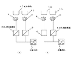
図1は誘導加熱調理器の外観斜視図、図2(a)(b)は加熱コイルの出力制御ブロック図を示すものである。 FIG. 1 is an external perspective view of an induction heating cooker, and FIGS. 2A and 2B are block diagrams of output control of a heating coil.
図において、1は誘導加熱調理器の本体である。2は絶縁板で、本体1の上面に水平に配置され、鉄等の磁性体又はアルミニウム等の非磁性体よりなる鍋等の被加熱物13を載置するものである。 In the figure, 1 is the main body of the induction heating cooker. Reference numeral 2 denotes an insulating plate which is horizontally disposed on the upper surface of the main body 1 and mounts an object to be heated 13 such as a pan made of a magnetic material such as iron or a non-magnetic material such as aluminum.
この絶縁板2の前面側上部の左右二箇所には後で述べる出力制御基板6と連動し、それぞれ通電の状態を表示する表示部A10、表示部B11が設けられている。
Display portions A10 and B11 for displaying the energization state are provided in two places on the left and right of the upper part of the front side of the insulating plate 2 in conjunction with an
3は加熱コイルA、4は加熱コイルBで、絶縁板2の下方で本体1内の上部右左に配置されており、絶縁板2上に載置された被加熱物13を加熱するものである。
3 is a heating coil A, and 4 is a heating coil B, which is disposed below the insulating plate 2 on the upper right and left sides in the main body 1 and heats an
5は本体1の前面右側に設けられた操作部で、加熱コイルA3、加熱コイルB4の加熱の設定、操作を行うものである。
6はこの操作部5と連動した出力制御基板で、本体1内の空間スペースに配置されており、加熱コイルA3、加熱コイルB4に対して被加熱物13が磁性体か非磁性体かを電流値にて判別し、その磁性体用と非磁性体用に合った2種類の高周波電力を供給するインバータ回路を搭載している。
7は吸気口で、本体1の後部において上方に向けて開口しており、本体1内部の出力制御基板6に冷却風を取り入れるための開口部である。
Reference numeral 7 denotes an air inlet that opens upward at the rear part of the main body 1 and is an opening for taking cooling air into the
8は排気口で、前記吸気口7と同様本体1の後部において上方に向けて開口された開口部である。本実施例では、吸気口7は本体1後部の右側に、排気口8は左側に配置している。 Reference numeral 8 denotes an exhaust port, which is an opening portion opened upward at the rear portion of the main body 1 as in the case of the intake port 7. In this embodiment, the intake port 7 is arranged on the right side of the rear part of the main body 1 and the exhaust port 8 is arranged on the left side.
9は本体1の前面左部に設けられたロースター加熱部である。なお、このロースター加熱部9は前面右側やほぼ中央に設置してもよい。 A roaster heating unit 9 is provided on the left side of the front surface of the main body 1. In addition, you may install this roaster heating part 9 in the front right side or substantially the center.
12は本体1内の後部スペースに設けられた冷却ファンで、出力制御基板6及び加熱コイルA3、加熱コイルB4へ冷却風を送風するものである。
Reference numeral 12 denotes a cooling fan provided in a rear space in the main body 1 for blowing cooling air to the
本発明の一実施例として、図2(a)に示す如く、使用者が鉄等磁性体の被加熱物13とアルミニウム等非磁性体の被加熱物13をそれぞれ加熱コイルA3、加熱コイルB4の上方に載置し、操作部5にて任意の出力に操作すると、出力制御基板6がこの加熱コイルA3、加熱コイルB4に対してそれぞれの被加熱物13が磁性体か非磁性体かを電流値にて判別し、磁性体の被加熱物13が載置された加熱コイルA3へは磁性体用の約21KHzの高周波電力を供給し、非磁性体の被加熱物13が載置された加熱コイルB4へは非磁性体用の約60KHz以上の高周波電力を供給する。このとき、表示部A10、表示部B11は、その通電状態を表示する。
As an embodiment of the present invention, as shown in FIG. 2 (a), the user sets the
なお、加熱コイルA3、B4に載置する被加熱物13の組み合わせを変えても出力制御基板6はそれぞれを判別し、磁性体用又は非磁性体用の高周波電力を供給する。
Even if the combination of the objects to be heated 13 placed on the heating coils A3 and B4 is changed, the
さらに両方の加熱コイルA3、B4へ非磁性体の被加熱物13を載置した場合には、非磁性体用の高周波電力を双方に駆動することができるよう出力制御基板6が制御する。
Furthermore, when the non-magnetic material to be heated 13 is placed on both the heating coils A3 and B4, the
なお、被加熱物の具体的な調理方法については、公知であり説明を省略する。 In addition, about the specific cooking method of to-be-heated material, it is well-known and description is abbreviate | omitted.
上記したように、本発明によれば、本体1内に加熱コイルA3、加熱コイルB4と、この加熱コイルA3、加熱コイルB4に対して被加熱物13が磁性体か非磁性体かを判別し、その判別結果に基づいて夫々磁性体用と非磁性体用の2種類の高周波電力を供給するインバータ回路を搭載した出力制御基板6を配置し、この出力制御基板6は被加熱物13の判別結果により磁性体用又は非磁性体用の高周波電力を選択し、加熱コイルA3、加熱コイルB4をほぼ同時に連続して非磁性体の被加熱物13を使用できるように制御するものである。
As described above, according to the present invention, the heating coil A3 and the heating coil B4 in the main body 1 and whether the object to be heated 13 is magnetic or non-magnetic with respect to the heating coil A3 and heating coil B4 are discriminated. An
これによって、使用できる鍋材質の制約や調理器本体の設置場所の制約を排除することができるものである。 As a result, restrictions on the pot material that can be used and restrictions on the installation location of the cooker body can be eliminated.
また加熱コイルA3、加熱コイルB4の通電中に、その通電を使用者に知らせる表示部A10、表示部B11を本体1に設けたものである。 The main body 1 is provided with a display unit A10 and a display unit B11 that notify the user of energization of the heating coil A3 and the heating coil B4.
これによって、使用者は加熱コイルA3、加熱コイルB4の使用状態を表示部A10、表示部B11により容易に知ることができるものである。 As a result, the user can easily know the usage state of the heating coil A3 and the heating coil B4 from the display unit A10 and the display unit B11.
1 本体
2 絶縁板
3 加熱コイルA
4 加熱コイルB
5 操作部
6 出力制御基板
7 吸気口
8 排気口
9 ロースター加熱部
10 表示部A
11 表示部B
12 冷却ファン
13 被加熱物
1 Body 2
4 Heating coil B
5
11 Display B
12
Claims (2)
前記加熱コイルA、加熱コイルBに対応した前記絶縁板上に磁性体である鉄製鍋、非磁性体であるアルミニウム製鍋が載置された場合には、該被加熱物に磁性体である鉄製鍋及び非磁性体であるアルミニウム製鍋用の異なる周波数の高周波電力を供給するように制御し、
前記加熱コイルA、加熱コイルBに対応した前記絶縁板上に非磁性体であるアルミニウム製鍋が載置された場合には、該アルミニウム製鍋に非磁性体用の周波数である約60KHz以上の高周波電力を供給し、前記出力制御回路及び前記加熱コイルA、加熱コイルBが冷却風で冷却されることで、加熱コイルA、加熱コイルBをほぼ同時に連続して使用できるように制御することを特徴とする誘導加熱調理器。 An insulating plate for placing an object to be heated is disposed on the upper surface of the main body, and the heating coil A and heating coil B and the object to be heated with respect to the heating coil A and heating coil B are disposed in the main body below the insulating plate. Discriminates whether it is a magnetic iron pan or a non-magnetic aluminum pan , and supplies high-frequency power for the magnetic iron pan and the non-magnetic aluminum pan based on the discrimination results , respectively. An output control board equipped with an inverter circuit is disposed, and the heating coil A and the heating coil B are both capable of heating an iron pan that is a magnetic material and an aluminum pan that is a non-magnetic material, and the output control board Determines whether the object to be heated is a magnetic iron pan or a non-magnetic aluminum pan with respect to the heating coil A and heating coil B by current value,
The heating coils A, iron pot of a magnetic material on the insulation plate corresponding to the heating coil B, and if the aluminum pan is placed a non-magnetic material, iron is a magnetic material to said heated Control to supply high frequency power of different frequency for pans and non-magnetic aluminum pans ,
The heating coils A, if the aluminum pan is placed a non-magnetic material on said insulating plate corresponding to the heating coil B is greater than or equal to about 60KHz which is the frequency for a non-magnetic material to the aluminum pan Supplying high-frequency power and controlling the output control circuit and the heating coil A and the heating coil B so that the heating coil A and the heating coil B can be used continuously almost simultaneously by cooling with cooling air. Induction heating cooker featuring.
前記加熱コイルA、前記加熱コイルBの通電中に、その通電を使用者に知らせる表示部A、表示部Bを本体に設けた誘導加熱調理器。 The induction heating cooker according to claim 1,
An induction heating cooker provided with a display unit A and a display unit B on the main body for notifying a user of energization during energization of the heating coil A and the heating coil B.
Priority Applications (1)
| Application Number | Priority Date | Filing Date | Title |
|---|---|---|---|
| JP2003282404A JP4215589B2 (en) | 2003-07-30 | 2003-07-30 | Induction heating cooker |
Applications Claiming Priority (1)
| Application Number | Priority Date | Filing Date | Title |
|---|---|---|---|
| JP2003282404A JP4215589B2 (en) | 2003-07-30 | 2003-07-30 | Induction heating cooker |
Related Child Applications (3)
| Application Number | Title | Priority Date | Filing Date |
|---|---|---|---|
| JP2005261491A Division JP4215761B2 (en) | 2005-09-09 | 2005-09-09 | Induction heating cooker |
| JP2007303872A Division JP2008078153A (en) | 2007-11-26 | 2007-11-26 | Induction heating cooker |
| JP2007303870A Division JP2008108738A (en) | 2007-11-26 | 2007-11-26 | Induction heating cooker |
Publications (3)
| Publication Number | Publication Date |
|---|---|
| JP2005050715A JP2005050715A (en) | 2005-02-24 |
| JP2005050715A5 JP2005050715A5 (en) | 2005-12-02 |
| JP4215589B2 true JP4215589B2 (en) | 2009-01-28 |
Family
ID=34267622
Family Applications (1)
| Application Number | Title | Priority Date | Filing Date |
|---|---|---|---|
| JP2003282404A Expired - Lifetime JP4215589B2 (en) | 2003-07-30 | 2003-07-30 | Induction heating cooker |
Country Status (1)
| Country | Link |
|---|---|
| JP (1) | JP4215589B2 (en) |
Families Citing this family (1)
| Publication number | Priority date | Publication date | Assignee | Title |
|---|---|---|---|---|
| KR101408265B1 (en) | 2011-04-22 | 2014-06-17 | 린나이코리아 주식회사 | Cooking method in a rice cooker |
-
2003
- 2003-07-30 JP JP2003282404A patent/JP4215589B2/en not_active Expired - Lifetime
Also Published As
| Publication number | Publication date |
|---|---|
| JP2005050715A (en) | 2005-02-24 |
Similar Documents
| Publication | Publication Date | Title |
|---|---|---|
| JP2008027601A (en) | Induction heating cooker | |
| JP4934364B2 (en) | Induction heating cooker | |
| JP2008311092A (en) | Induction heating cooker | |
| JP4751793B2 (en) | Induction heating cooker | |
| JP5026364B2 (en) | Induction cooking device | |
| JP2004186002A (en) | Electromagnetic induction cooker | |
| JP4215761B2 (en) | Induction heating cooker | |
| JP4215589B2 (en) | Induction heating cooker | |
| JP5159505B2 (en) | Cooker | |
| JP3990942B2 (en) | Induction heating cooker | |
| JP2008108738A (en) | Induction heating cooker | |
| JP2008078153A (en) | Induction heating cooker | |
| JP3991038B2 (en) | Induction heating cooker | |
| JP5860766B2 (en) | Induction heating cooker | |
| JP2005056684A (en) | Induction heating cooker | |
| JP2005122963A (en) | Induction heating cooker | |
| JP2005243535A (en) | Induction heating device | |
| WO2012157189A1 (en) | Induction heat cooker | |
| JP2002058600A (en) | Electric cooker | |
| JP4972617B2 (en) | Induction heating cooker | |
| JP2003185157A (en) | Heating cooker | |
| JP3845277B2 (en) | rice cooker | |
| JP2005166568A (en) | Heating cooker | |
| JP2003068434A (en) | Heating cooker | |
| JP2005093302A (en) | Induction heating cooker |
Legal Events
| Date | Code | Title | Description |
|---|---|---|---|
| A711 | Notification of change in applicant |
Free format text: JAPANESE INTERMEDIATE CODE: A712 Effective date: 20050525 |
|
| A521 | Request for written amendment filed |
Free format text: JAPANESE INTERMEDIATE CODE: A523 Effective date: 20050909 |
|
| A621 | Written request for application examination |
Free format text: JAPANESE INTERMEDIATE CODE: A621 Effective date: 20050909 |
|
| A521 | Request for written amendment filed |
Free format text: JAPANESE INTERMEDIATE CODE: A523 Effective date: 20050909 |
|
| RD02 | Notification of acceptance of power of attorney |
Free format text: JAPANESE INTERMEDIATE CODE: A7422 Effective date: 20060511 |
|
| RD04 | Notification of resignation of power of attorney |
Free format text: JAPANESE INTERMEDIATE CODE: A7424 Effective date: 20060511 |
|
| A711 | Notification of change in applicant |
Free format text: JAPANESE INTERMEDIATE CODE: A712 Effective date: 20061005 |
|
| A131 | Notification of reasons for refusal |
Free format text: JAPANESE INTERMEDIATE CODE: A131 Effective date: 20070925 |
|
| A521 | Request for written amendment filed |
Free format text: JAPANESE INTERMEDIATE CODE: A523 Effective date: 20071126 |
|
| A02 | Decision of refusal |
Free format text: JAPANESE INTERMEDIATE CODE: A02 Effective date: 20080603 |
|
| A521 | Request for written amendment filed |
Free format text: JAPANESE INTERMEDIATE CODE: A523 Effective date: 20080730 |
|
| A521 | Request for written amendment filed |
Free format text: JAPANESE INTERMEDIATE CODE: A523 Effective date: 20080704 |
|
| A911 | Transfer to examiner for re-examination before appeal (zenchi) |
Free format text: JAPANESE INTERMEDIATE CODE: A911 Effective date: 20080813 |
|
| TRDD | Decision of grant or rejection written | ||
| A01 | Written decision to grant a patent or to grant a registration (utility model) |
Free format text: JAPANESE INTERMEDIATE CODE: A01 Effective date: 20081028 |
|
| A01 | Written decision to grant a patent or to grant a registration (utility model) |
Free format text: JAPANESE INTERMEDIATE CODE: A01 |
|
| A61 | First payment of annual fees (during grant procedure) |
Free format text: JAPANESE INTERMEDIATE CODE: A61 Effective date: 20081104 |
|
| R150 | Certificate of patent or registration of utility model |
Free format text: JAPANESE INTERMEDIATE CODE: R150 Ref document number: 4215589 Country of ref document: JP Free format text: JAPANESE INTERMEDIATE CODE: R150 |
|
| FPAY | Renewal fee payment (event date is renewal date of database) |
Free format text: PAYMENT UNTIL: 20111114 Year of fee payment: 3 |
|
| FPAY | Renewal fee payment (event date is renewal date of database) |
Free format text: PAYMENT UNTIL: 20111114 Year of fee payment: 3 |
|
| FPAY | Renewal fee payment (event date is renewal date of database) |
Free format text: PAYMENT UNTIL: 20121114 Year of fee payment: 4 |
|
| FPAY | Renewal fee payment (event date is renewal date of database) |
Free format text: PAYMENT UNTIL: 20121114 Year of fee payment: 4 |
|
| FPAY | Renewal fee payment (event date is renewal date of database) |
Free format text: PAYMENT UNTIL: 20131114 Year of fee payment: 5 |
|
| S531 | Written request for registration of change of domicile |
Free format text: JAPANESE INTERMEDIATE CODE: R313531 |
|
| S533 | Written request for registration of change of name |
Free format text: JAPANESE INTERMEDIATE CODE: R313533 |
|
| R350 | Written notification of registration of transfer |
Free format text: JAPANESE INTERMEDIATE CODE: R350 |
|
| EXPY | Cancellation because of completion of term |