JP4215355B2 - Communications system - Google Patents
Communications system Download PDFInfo
- Publication number
- JP4215355B2 JP4215355B2 JP29178699A JP29178699A JP4215355B2 JP 4215355 B2 JP4215355 B2 JP 4215355B2 JP 29178699 A JP29178699 A JP 29178699A JP 29178699 A JP29178699 A JP 29178699A JP 4215355 B2 JP4215355 B2 JP 4215355B2
- Authority
- JP
- Japan
- Prior art keywords
- data
- node
- byte
- virtual
- virtual containers
- Prior art date
- Legal status (The legal status is an assumption and is not a legal conclusion. Google has not performed a legal analysis and makes no representation as to the accuracy of the status listed.)
- Expired - Fee Related
Links
- 238000004891 communication Methods 0.000 title claims abstract description 22
- 238000000034 method Methods 0.000 claims description 18
- 230000001934 delay Effects 0.000 claims description 6
- 230000001360 synchronised effect Effects 0.000 claims description 6
- 238000002372 labelling Methods 0.000 claims 3
- 230000005540 biological transmission Effects 0.000 description 14
- 238000007726 management method Methods 0.000 description 11
- 238000013507 mapping Methods 0.000 description 10
- 238000010586 diagram Methods 0.000 description 8
- 230000007246 mechanism Effects 0.000 description 4
- 238000000605 extraction Methods 0.000 description 3
- 238000003780 insertion Methods 0.000 description 3
- 230000037431 insertion Effects 0.000 description 3
- 230000008569 process Effects 0.000 description 3
- 241001522296 Erithacus rubecula Species 0.000 description 2
- 230000001413 cellular effect Effects 0.000 description 1
- 230000008859 change Effects 0.000 description 1
- 230000002301 combined effect Effects 0.000 description 1
- 125000004122 cyclic group Chemical group 0.000 description 1
- 238000013500 data storage Methods 0.000 description 1
- 230000007547 defect Effects 0.000 description 1
- 238000005516 engineering process Methods 0.000 description 1
- 230000001788 irregular Effects 0.000 description 1
- 238000012423 maintenance Methods 0.000 description 1
- 230000008520 organization Effects 0.000 description 1
- 238000011084 recovery Methods 0.000 description 1
- 230000004044 response Effects 0.000 description 1
Images


Classifications
-
- H—ELECTRICITY
- H04—ELECTRIC COMMUNICATION TECHNIQUE
- H04J—MULTIPLEX COMMUNICATION
- H04J3/00—Time-division multiplex systems
- H04J3/16—Time-division multiplex systems in which the time allocation to individual channels within a transmission cycle is variable, e.g. to accommodate varying complexity of signals, to vary number of channels transmitted
- H04J3/1605—Fixed allocated frame structures
- H04J3/1611—Synchronous digital hierarchy [SDH] or SONET
- H04J3/1617—Synchronous digital hierarchy [SDH] or SONET carrying packets or ATM cells
-
- H—ELECTRICITY
- H04—ELECTRIC COMMUNICATION TECHNIQUE
- H04J—MULTIPLEX COMMUNICATION
- H04J2203/00—Aspects of optical multiplex systems other than those covered by H04J14/05 and H04J14/07
- H04J2203/0001—Provisions for broadband connections in integrated services digital network using frames of the Optical Transport Network [OTN] or using synchronous transfer mode [STM], e.g. SONET, SDH
- H04J2203/0073—Services, e.g. multimedia, GOS, QOS
- H04J2203/008—Support of video
-
- H—ELECTRICITY
- H04—ELECTRIC COMMUNICATION TECHNIQUE
- H04J—MULTIPLEX COMMUNICATION
- H04J2203/00—Aspects of optical multiplex systems other than those covered by H04J14/05 and H04J14/07
- H04J2203/0001—Provisions for broadband connections in integrated services digital network using frames of the Optical Transport Network [OTN] or using synchronous transfer mode [STM], e.g. SONET, SDH
- H04J2203/0073—Services, e.g. multimedia, GOS, QOS
- H04J2203/0082—Interaction of SDH with non-ATM protocols
- H04J2203/0085—Support of Ethernet
-
- H—ELECTRICITY
- H04—ELECTRIC COMMUNICATION TECHNIQUE
- H04J—MULTIPLEX COMMUNICATION
- H04J2203/00—Aspects of optical multiplex systems other than those covered by H04J14/05 and H04J14/07
- H04J2203/0001—Provisions for broadband connections in integrated services digital network using frames of the Optical Transport Network [OTN] or using synchronous transfer mode [STM], e.g. SONET, SDH
- H04J2203/0089—Multiplexing, e.g. coding, scrambling, SONET
- H04J2203/0094—Virtual Concatenation
-
- H—ELECTRICITY
- H04—ELECTRIC COMMUNICATION TECHNIQUE
- H04J—MULTIPLEX COMMUNICATION
- H04J3/00—Time-division multiplex systems
- H04J3/02—Details
- H04J3/06—Synchronising arrangements
- H04J3/0635—Clock or time synchronisation in a network
- H04J3/0685—Clock or time synchronisation in a node; Intranode synchronisation
Abstract
Description
【0001】
【発明の属する技術分野】
本発明は、広帯域データ信号を同期デジタル・ハイアラーキ・ネットワーク(SDH)を通じて送信する通信システムに関する。
【0002】
【従来の技術】
過去十年の間に新しい規格が出現するにともない、通信ネットワーク内でのデジタル送信ベアラーの選択が拡大している。プレジオクロナス・デジタル・ハイアラーキ(PDH)は、1.544Mbit/s、2.048Mbit/s、34,368Mbit/sおよび139.468Mbit/sのような標準インターフエィス速度を提供していたが、同期デジタル・ハイアラーキ(SDH)に今や取って代わられている。SDHは、信号をバーチャル・コンテナに「マッピング」してPDHインターフエィス速度で伝送する。事実、現在のSDH装置のインターフエィスの大部分はPDHの速度である。この「マッピング」の特徴は、将来の信号のタイプも古い信号のタイプも平行してSDHネットワーク上で送信できることにある。また、SDH内では対策が、既存の装置と互換性を残しながら、信号の帯域幅を拡大するためにとられてきた。
【0003】
PDHとSDHシステムは両方とも、一定でかつ中断しないデータ・ビットのストリームで信号を伝送することで最大効率化されているので、時分割多重方式(TDM)と呼ばれる広い範疇に入る。
【0004】
【発明が解決しようとする課題】
この最大効率化の結果、伝統的な音声トラフィックは多様な容量レベルでもって合理的な効率で送信されることができる。これに対して、ほとんどがパケット形式であるデータ・タイプの信号は、SDHおよびPDHシステム上を伝送される時、送信の非効率さを被る。この非効率さの主原因は、選ばれたパケット・レートの帯域幅に対して適当なコンテナの大きさが存在しない時に生ずる。
【0005】
逆多重化は、既存のより低いビット速度の通信チャネルまたはベアラーを介して、非標準のまたはより高速のビット速度の信号を送信する方法である。逆多重化に使用されるより低速のチャネル数と所要のパケット速度を注意深く一致させることで、TDM装置を用いて効率的なデータ送信システムが構築できる。
【0006】
逆多重化は、非同期伝送モード(ATM)トラフィックの処理に特別に適している。セル対セル・ベースの広帯域ATM信号を分割かつ再構築することで、ATMセルを低容量PDH信号に逆多重化するための方法(IMAと呼ばれる)が開発されている。その後に、これらPDH信号がSDH伝送システム上にマッピングされることができ、IMAがSDH上で行なわれる時は何時でも不要な信号を処理する2ステージ処理を生ずる。さらに、IMA方法を他のタイプの広帯域データ信号に適用することは、IMAにより使用される制御および通信機構はATMセルの存在に依存するために難しい。
【0007】
本発明は、逆多重化方法をSDH伝送システムによりふさわしくより効率的でかつ既存のSDH装置と互換性のある方法で使用して、改良した通信を提供することを目的とする。
【0008】
【課題を解決するための手段】
本発明によれば、2ノード間にSDHパスを有する通信システムであって、当該パスに所定の帯域幅のバーチャル・コンテナを有するものにおいて、一のノードにおいて当該所定の帯域幅より大きい帯域幅のパケット形式のデータを受信する手段と、当該データをパケット境界にかかわらずバイト形式に逆多重化して複数のバーチャル・コンテナで他のノードに送信する手段と、他のノードにおいてこのデータを受信して再集合化する手段と、個々のバーチャル・コンテナの相違するパス長により生ずる遅延を補償する手段と、を有する。
【0009】
この通信システムは、広い範囲の広帯域幅のデータ・タイプに適しており、SDH伝送システムにより導入される特別のタイミング欠陥を補償することができる。
【0010】
周知の通り、バーチャル・コンテナは論理的な存在であり、同期伝送モジュール(STM)にのみ存在し、そしてオーバーヘッド情報とペイロードのデータの両方を含む。異なるタイプのバーチャル・コンテナが、国際規格機関により定義され、各コンテナの大きさと構造、ペイロードのデータの形式とデータのタイミングを符号化する方法、管理及び維持目的のためのオーバーヘッド・バイトの使用が決められる。現在のバーチャル・コンテナ(VC−n)は、VC−12、VC−2、VC−3およびVC−4を含む。
【0011】
本発明は、VC−IM−nと表示された新しい逆多重化マッピングを伝送するため、既存のバーチャル・コンテナを使用する方法を提案する。
【0012】
バイト・マッピングの使用は、元の信号のデジタル内容とその位相/周波数特性を、ATMセル方式システムにより必要とされるであろう帯域幅を過剰に使用をしなくても、正確に保存することができる。
【0013】
【発明の実施の形態】
図1を参照して、逆多重化の原理を説明する。図1において、相対的に広帯域のデータ信号がそれぞれより狭い帯域幅のベアラーのチャネルを持つネットワーク上を伝送される。これらベアラーのチャネルの数は、広帯域データを一緒に収容できるものが割り当てられている。
【0014】
すなわち、xMbit/sの帯域幅を有する入力データ信号1は、信号分断器2に入力されて、いくつかの狭帯域の信号、それぞれ典型的には2Mbit/s、に分断されて、nチャネル3を経てユニット4に送信され、そこで信号が再集合される。一般的に全てのチャネル3の伝送時間は同じでないので、ユニット4は入力信号の時間を調整し、各チャネル3の様様な相対的遅延を補償する。これにより、元の信号は再構成されて、出力信号5として出力される。このような、逆多重化技術は、相対的に狭帯域幅容量を持つ既存の通信回路を経て個々のデータ信号を送信する必要がある時に用いられる。
【0015】
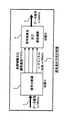
図2は、本発明の実施例を図式的に示すものである。図2では、信号が装置21から装置22へ、データを典型的に標準の2Mbit/s帯域幅を各々持つバーチャル・コンテナ(VC)23内に入れて伝送するように構成されたSDH通信システムを経て送られる。
【0016】
装置21は、三つのタイプの入力信号を有するように示されているが、実際には他のデータ速度および他の入力信号のタイプもまた入力される。LAN信号24は8Mbit/sの帯域幅を有しイーサネット・インターフエィス25により受信される。デジタル化ビデオ信号26は5Mbit/sの帯域幅を有しビデオCODECインターフエィス27により受信される。そしてATM信号28は20Mbit/sの帯域幅を有しATMアダプタ29により受信される。すなわち、データはバイト、セラーパケット形式で受信可能である。
【0017】
この三つのタイプの信号は、図3を参照してその機能が詳細に説明されるVC−IM(仮想コンテナ−逆多重化)ユニット30により、バイト形式でマッピングされる。
【0018】
要するに、ユニット30は広帯域入力信号を2Mbit/sのストリームに変換し、各ストリームをバーチャル・コンテナで通信システム23を経て装置22へ伝送し、装置22内のユニット31はバーチャル・コンテナを非マップ化しそしてそれぞれバーチャル・コンテナが経由した様様の通信パスにより生じた相対的な遅延を補償する。
【0019】
非マップ化されると、元の信号が再形成され、それぞれのインターフエィス・ユニット32、33、34を経由して場合に応じてLAN信号、デジタル化ビデオ信号、ATM信号として出力するために送られる。入力信号を逆多重化技術を用いてバイト形式にマッピングしてバーチャル・コンテナに入れることにより、利用できるSDHの帯域幅を効率的に使用できる結果となり、SDHネットワークの中間ノードを修正する必要がない。
【0020】
以下に説明するように、元の信号を逐次バイトに分断し、そしてその後に元のデータ・ストリームに再集合するに用いられる方法は、SDHシステム内でデータ信号を送信するために最大効率化されており、広帯域信号のタイミング特性を保存する共に各VC(バーチャル・コンテナ)により経験される差分的パス遅延の補償も含む。
【0021】
送信装置21により代表されるVC−IM送信機能が、特定の入力信号タイプ、この場合はパケットまたはセル形式と仮定する、に関して図3に示されている。データ・アダプタ機能40が広帯域信号41中のデータ・パケットまたはセルを受け取り、パケットまたはセルのアドレスに関連するいかなるルーテイング機能も実行する。不規則な時間間隔でデータ・アダプタ40に到着することができるパケットまたはセルは、データ線形化器42内で連続データ・ストリームに変換される。定常なストリームのデータを作成するに用いられる手法は、十分に標準化されており、定義されている。たとえば、ATM信号については、実際のデータを運ぶセルの間に空のセルを導入するという手法が存在する。
【0022】
データ線形化器からの定常なストリームのデータは、その後にデータ分断器43によりパケットまたはセル境界に関係無く、8ビット・バイトに分断される。データの引き続く各バイトは、順に、すなわち、ラウンド・ロビン方式で、m個のVC−nリンクの各々に挿入される。バイト順序の情報を見失はないようにするため、三レベル順序番号付け方法が使用される。この方法は、図5を参照してVC−IM−12マッピングの場合を考える時により詳細に検討される。
【0023】
データ分断器43は、V5、J2、N2およびK4バイトからなるVC−12パスオーバーヘッド(POH)を持つ標準のSDH VC−12コンテナの500マイクロセカンドのマルチフレーム・フォーマットを構築する。この構造は、既存のSDHネットワーク内で各VCM−IM−12リンクが運ばれる時、互換性を保証する。オーバーヘッド・バイト挿入機能45は、予備のSDHオーバーヘッド・スロットを利用して、VC−IMマッピングに特有の新バイトを挿入する。すなわち、以下に詳細に説明されるフレーム番号指示子(FNUM)、新しい通信メッセージが受け取られたことを示すメッセージ・チエック(MCHK)バイトおよびメッセージ番号(MSN)、図5において詳細に示される6マルチフレーム・オーバーヘッド・バイト(OHB0−OHB5)である。
【0024】
第一レベルの順序番号付けは、VC−12の標準的マッピング方法の一部をなすTU−12ポインタを利用する。TU−12ポインタは、マルチフレーム内の他の全てのバイトが一定の相対的位置を維持するVC−IM−12マルチフレーム62内のV5バイト61の位置を定義する。この結果、データがマッピングされる128ペイロード・バイトの順序が各VC−IM−12内で明確に定義される。
【0025】
第二レベルの順序番号付け構成は、オーバーヘッド・スーパーフレーム(図6)内のリンク順序識別子(LSI)の使用を含む。オーバーヘッド・スーパーフレームは、各8VC−IM−12マルチフレーム(図5)ごとに繰り返される構造を持ち、VC−IMグループのネットワーク接続を標識付けおよび追跡するために管理システムにより使用されるグループID(GID)およびリンクID(LID)値と、VC−IM−12接続の両端間に通信および制御メッセージを運ぶために使用される32メッセージ・バイト(MSGB0−MSGB31)と、一つのLSIバイトとを含む。送信側において、VC−IM−12グループを構成するm個のVC−12リンクの各々に独特のLSI番号が与えられ、バイトを連続したVC−12内に挿入するために用いられるラウンド・ロビン順序を識別する。
【0026】
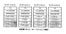
図7は、VC−IM−12送信機の出力において、第一および第二レベルのバイト順序番号付けの組合せ効果の例を示す。図7では、グループは4リンクからなり、データ・パケット・サイズは13バイトである。第一リンクの第一ペイロード・バイト71は、データストリームのバイト1を含む。第一リンクの第二ペイロード・バイト73にデータストリームのバイト5が挿入されるまで第二リンクの第一ペイロード・バイト72は、データストリームのバイト2を含む。これは、バイト13まで続けられ、その後に、次のデータパケットのバイト1(もし新パケットがなければ詰物バイト)が第二リンクの第4番目のペイロード・バイト74にマッピングされる。オーバーヘッド・スーパーフレーム内で運ばれるLSI値は、図7の各リンク対して表示される。
【0027】
VC−IM−4マッピングの場合、同様のオーバーヘッド構造(図8)が存在し、VC−4に関連したAU−4ポインタ内に第二レベルの順序番号付けが含まれると共に、LSIバイトを含んでいる。他のSDHコンテナ・レート(たとえばVC−2およびVC−3)に対応して、さらにVC−IM−nマッピング・フォーマットは、VC−IM−12またはVC−IM−4フォーマットのいずれかに類似している。
【0028】
第三レベルの順序番号付け構成は、図5、7および8に示されるFNUM値を使用する。オーバーヘッド・バイト挿入機能45は、FNUM位置に循環的番号付けバイトを、連続するマルチフレーム(VC−IM−12)またはフレーム(VC−IM−4)で十進数値で増加が0から255となるように、付け加える。FNUM値が255に到達すると、次のマルチフレーム/フレームは0のFNUM値を含み、そして以前と同様に増加する。
【0029】
同じグループに属する全てのリンク内において送信されるFNUM値は、図7中の各リンクにおける例示の値151のように、一致する。しかし、受信側に到達した時は、各VC−IM−12リンクのパス遅延の違いにより異なることがある。
【0030】
図4に示すVC−IM−n接続の受信側においては、元のデータ信号が入力するVC−nリンクから復元される。復元工程は、主として、三レベル順序番号付け構成を用いて符号化した際の元のデータ順序を識別すること、そして個別のリンク上に発生した相違する遅延を補償することである。
【0031】
通常のSDH VC−n信号の非多重化のためのメカニズムは、個別のVCの各々に対して、VC受信機能55内で実行される。たとえば、VC−12信号に対しては、TU−12ポインタを解釈してV5バイトの位置を決定し、オーバーヘッド・バイトV5、J2、N2およびK4を回復し、これらオーバーヘッド・バイトの値に基づいて管理機能を実行する。
【0032】
一旦、TUまたはAUポインタがVC−IM−nフレーム(たとえば図5及び図8)の開始を見つけると、第二レベルの順序復号化を実行することができる。これは、FNUM値とLSIバイト値を抽出するために、オーバーヘッド・バイト抽出ユニット50でVC−IM−nのオーバーヘッド・バイトにアクセスすることを含む。オーバーヘッド・バイト抽出ユニット50はまた、MSGBnバイトに含まれる32バイト・メッセージをリンク/グループ管理ユニット51へ送る。リンク/グループ管理機能は、グループの状態に関して送信側と通信の送受を行い、そして、VC−IMデータ伝送機構を制御する。
【0033】
抽出されたLSIおよびFNUMは、同時的に使用されて、遅延補償及びデータ再集合ユニット52に入るSDHフレーム同期バイトを再配列し、ユニット52から出て行くデータストリームを作成する。このデータストリームにおいては、より低いFNUM値を持つバイトが先に出て、同じFNUM値ではより低いLSI数のバイトが先に出る。ユニット52には、データ記憶装置が組み込まれていて、グループ内の最速リンクと最遅リンク間の最大遅延に関係するバイト数を記憶する。この単純な最配列機構は、遅延が+/−(FNUMMAX/2)VC−IM−nフレームより大きくない限り、バイトの順序の完全性を維持する。VC−12では、これは最小(128xFNUM/2xN)バイト、ここでNはグループ内のリンク数、を記憶できるデータ記憶に対応する。復元された広帯域信号は、そしてアダプタ53で、VC−IM接続上で伝送されている信号のタイプに応じて適当なインターフエィス・フオーマットに変換される。タイミング発生器54により提供される再タイミング機能はSDHシステム・クロックを使用して出力される広帯域信号の位相/周波数特性を生成する。
【0034】
VC−IM−nグループは、図1に示すように、ネットワークを横断する適当なVC−nチャネル3接続を必要とする。これは既存のSDHネットワーク管理機能を使用することで、VC−IM機能の管理とは独立して行うことができる。オーバーヘッド・スーパーフレーム(図6)は、追加的な2局間VC−IM−n構成情報を通信するため32バイト・メッセージ信号を含む。このメッセージ信号は、変化するトラフィツクに対応して臨時のリンクの追加または既存のリンクの取り外しのような、VC−IMグループのサイズの動的変化を再調整する際に、システムの端末間で通信するために用いられる。もし中間のSDH装置がVC−IM−nオーバーヘッドを認識できない場合は、SDHタイプのオーバーヘッドをこのようにVCM−IMグループを管理するために用いることにより、柔軟な管理システムを、現在のSDHネットワーク管理機能内に組み込むことかあるいはVC−IM−n経路の各端末の装置にアクセスする別個のコントローラにより管理することで、達成できる。
【図面の簡単な説明】
【図1】逆多重化を説明する概略図。
【図2】本発明の一実施例を説明するブロック図。
【図3】本発明の送信側の構成を詳細に説明するブロック図。
【図4】本発明の受信側の構成を詳細に説明するブロック図。
【図5】本発明のマルチフレーム構成を説明する図。
【図6】本発明のオーバーヘッド・スーパーフレーム構成を説明する図。
【図7】本発明の送信側のマッピング順序を示す図。
【図8】本発明のインターフエィス信号フォーマットを示す図。
【符号の説明】
21 送信装置
22 受信装置
40 データ・アダプタ
42 データ線形化器
43 データ分断器
44 リンク/グループ管理
45 オーバーヘッド・バイト挿入
50 VC−IM−nオーバーヘッド・バイト抽出
51 リンク/グループ管理
52 遅延補償及びデータ再集合[0001]
BACKGROUND OF THE INVENTION
The present invention relates to a communication system for transmitting broadband data signals through a synchronous digital hierarchy network (SDH).
[0002]
[Prior art]
With the emergence of new standards over the past decade, the choice of digital transmission bearers within communication networks has expanded. Pregeochronous Digital Hierarchy (PDH) provided standard interface speeds such as 1.544 Mbit / s, 2.048 Mbit / s, 34,368 Mbit / s and 139.468 Mbit / s, but synchronized Digital Hierarchy (SDH) has now been replaced. SDH “maps” signals to virtual containers and transmits them at PDH interface speeds. In fact, most of the current SDH equipment interface is the speed of PDH. This "mapping" is characterized by the ability to transmit future and old signal types in parallel over the SDH network. In SDH, measures have been taken to expand the signal bandwidth while remaining compatible with existing devices.
[0003]
Both PDH and SDH systems fall into a broad category called time division multiplexing (TDM) because they are maximized in efficiency by transmitting signals in a stream of constant and uninterrupted data bits.
[0004]
[Problems to be solved by the invention]
As a result of this maximum efficiency, traditional voice traffic can be transmitted with reasonable efficiency with various capacity levels. In contrast, data type signals, mostly in packet format, suffer transmission inefficiencies when transmitted over SDH and PDH systems. The main cause of this inefficiency occurs when there is no suitable container size for the chosen packet rate bandwidth.
[0005]
Demultiplexing is a method of transmitting non-standard or higher bit rate signals over existing lower bit rate communication channels or bearers. By carefully matching the number of slower channels used for demultiplexing with the required packet rate, an efficient data transmission system can be constructed using a TDM device.
[0006]
Demultiplexing is particularly suitable for handling asynchronous transmission mode (ATM) traffic. A method (referred to as IMA) has been developed for demultiplexing ATM cells into low-capacity PDH signals by splitting and reconstructing cell-to-cell based wideband ATM signals. These PDH signals can then be mapped onto the SDH transmission system, resulting in a two-stage process that processes unwanted signals whenever IMA is performed on SDH. Furthermore, applying the IMA method to other types of wideband data signals is difficult because the control and communication mechanisms used by IMA depend on the presence of ATM cells.
[0007]
The present invention aims to provide an improved communication using the demultiplexing method in a way that is more suitable and more efficient for SDH transmission systems and compatible with existing SDH equipment.
[0008]
[Means for Solving the Problems]
According to the present invention, in a communication system having an SDH path between two nodes and having a virtual container having a predetermined bandwidth in the path, a bandwidth larger than the predetermined bandwidth in one node. Means for receiving data in packet format, means for demultiplexing the data in byte format regardless of packet boundaries and transmitting it to other nodes in a plurality of virtual containers, and receiving this data in other nodes Means for re-aggregating and means for compensating for delays caused by different path lengths of the individual virtual containers.
[0009]
This communication system is suitable for a wide range of high bandwidth data types and can compensate for special timing defects introduced by SDH transmission systems.
[0010]
As is well known, a virtual container is a logical entity, exists only in the synchronous transmission module (STM), and includes both overhead information and payload data. Different types of virtual containers are defined by the International Standards Organization, and the size and structure of each container, how to encode the payload data format and data timing, and the use of overhead bytes for management and maintenance purposes. It is decided. Current virtual containers (VC-n) include VC-12, VC-2, VC-3 and VC-4.
[0011]
The present invention proposes a method of using an existing virtual container to transmit a new demultiplexing mapping denoted VC-IM-n.
[0012]
The use of byte mapping accurately preserves the digital content of the original signal and its phase / frequency characteristics without excessive use of the bandwidth that would be required by an ATM cellular system. Can do.
[0013]
DETAILED DESCRIPTION OF THE INVENTION
The principle of demultiplexing will be described with reference to FIG. In FIG. 1, relatively wideband data signals are each transmitted over a network having a narrower bearer channel. The number of channels of these bearers is allocated to accommodate broadband data together.
[0014]
That is, an
[0015]
FIG. 2 schematically shows an embodiment of the invention. In FIG. 2, an SDH communication system configured to transmit signals from device 21 to device 22 in a virtual container (VC) 23, each typically having a standard 2 Mbit / s bandwidth, is shown. Sent via.
[0016]
Device 21 is shown as having three types of input signals, but in practice other data rates and other types of input signals are also input. The
[0017]
These three types of signals are mapped in byte form by a VC-IM (virtual container-demultiplexing)
[0018]
In short, the
[0019]
When unmapped, the original signal is reshaped and sent for output as a LAN signal, digitized video signal, or ATM signal via the
[0020]
As described below, the method used to break up the original signal into sequential bytes and then re-assemble into the original data stream is maximized for transmitting the data signal within the SDH system. It also preserves the timing characteristics of the wideband signal and includes compensation for differential path delay experienced by each VC (virtual container).
[0021]
The VC-IM transmission function represented by the transmitter 21 is shown in FIG. 3 with regard to a specific input signal type, in this case packet or cell format.
[0022]
The steady stream of data from the data linearizer is then divided into 8-bit bytes by the
[0023]
[0024]
First level sequence numbering utilizes TU-12 pointers that are part of the standard mapping method of VC-12. The TU-12 pointer defines the location of the
[0025]
The second level sequence numbering configuration involves the use of a link sequence identifier (LSI) in the overhead superframe (FIG. 6). The overhead superframe has a structure that repeats every 8 VC-IM-12 multiframe (FIG. 5), and the group ID (used by the management system to mark and track the network connection of the VC-IM group). GID) and link ID (LID) values, 32 message bytes (MSGB0-MSGB31) used to carry communication and control messages between both ends of the VC-IM-12 connection, and one LSI byte . On the transmitting side, each of the m VC-12 links that make up the VC-IM-12 group is given a unique LSI number and is used to insert bytes into the consecutive VC-12 round robin order Identify
[0026]
FIG. 7 shows an example of the combined effect of first and second level byte order numbering at the output of a VC-IM-12 transmitter. In FIG. 7, the group consists of 4 links, and the data packet size is 13 bytes. The first payload byte 71 of the first link contains
[0027]
For VC-IM-4 mapping, there is a similar overhead structure (FIG. 8), including second level sequence numbering in the AU-4 pointer associated with VC-4 and including LSI bytes. Yes. Corresponding to other SDH container rates (eg VC-2 and VC-3), the VC-IM-n mapping format is similar to either the VC-IM-12 or VC-IM-4 format. ing.
[0028]
The third level sequence numbering configuration uses the FNUM values shown in FIGS. The overhead byte insertion function 45 increases the cyclic numbering byte at the FNUM position from 0 to 255 as a decimal value in consecutive multiframe (VC-IM-12) or frame (VC-IM-4). So add. When the FNUM value reaches 255, the next multiframe / frame contains an FNUM value of 0 and increases as before.
[0029]
The FNUM values transmitted in all the links belonging to the same group are coincident like the
[0030]
On the receiving side of the VC-IM-n connection shown in FIG. 4, the original data signal is restored from the VC-n link that is input. The restoration process is primarily to identify the original data order when encoded using a three-level sequence numbering scheme and to compensate for the different delays that have occurred on the individual links.
[0031]
The mechanism for demultiplexing of normal SDH VC-n signals is performed within the VC receive
[0032]
Once the TU or AU pointer finds the start of a VC-IM-n frame (eg, FIGS. 5 and 8), second level order decoding can be performed. This includes accessing the overhead bytes of the VC-IM-n with the overhead
[0033]
The extracted LSI and FNUM are used simultaneously to reorder the SDH frame sync bytes entering the delay compensation and
[0034]
The VC-IM-n group requires an appropriate VC-
[Brief description of the drawings]
FIG. 1 is a schematic diagram illustrating demultiplexing.
FIG. 2 is a block diagram illustrating an embodiment of the present invention.
FIG. 3 is a block diagram illustrating in detail the configuration of the transmission side of the present invention.
FIG. 4 is a block diagram illustrating in detail the configuration of the receiving side of the present invention.
FIG. 5 is a diagram illustrating a multiframe configuration according to the present invention.
FIG. 6 is a diagram illustrating an overhead superframe configuration according to the present invention.
FIG. 7 is a diagram showing a mapping order on the transmission side according to the present invention.
FIG. 8 is a diagram showing an interface signal format according to the present invention.
[Explanation of symbols]
21 Transmitter 22
Claims (3)
一方の前記ノードにおいて、前記所定の帯域幅より大きな帯域幅を持った、バイト形式データ、セル形式データ、パケット形式データのうちの少なくとも1つを含む入力データを受信する手段と、
前記入力データを他方の前記ノードへ伝送するためパケット又はセル境界にかかわらずバイト形式で複数のバーチャル・コンテナ上に逆多重化する手段とを有し、
前記他方のノードにおいて、前記データを受信し再集合する手段と、
個々のバーチャル・コンテナの異なるパス長に起因する遅延を補償する手段とを有し、
前記複数のバーチャル・コンテナがある位相関係を有しており、
さらに、前記一方のノードにおいて各バーチャル・コンテナ内に、前記位相関係を示すデータ、バーチャル・コンテナのグループのネットワーク接続の標識付け及び追跡に対する管理データ、及び前記一方のノードから前記他方のノードへの通信及び制御メッセージを搬送するためのデータを挿入する手段とを有する、
前記システム。A communication system comprising an SDH (synchronous digital hierarchy) path between two nodes, the path having a virtual container of a predetermined bandwidth,
Means for receiving input data including at least one of byte format data, cell format data, and packet format data having a bandwidth larger than the predetermined bandwidth at one of the nodes;
Means for demultiplexing onto a plurality of virtual containers in byte form regardless of packet or cell boundaries to transmit the input data to the other node;
Means for receiving and re-aggregating the data at the other node;
Means to compensate for delays due to different path lengths of individual virtual containers;
The plurality of virtual containers have a topological relationship;
Further, in each virtual container at the one node, data indicating the topological relationship, management data for labeling and tracking network connections of a group of virtual containers, and from one node to the other node Means for inserting data for carrying communication and control messages ;
Said system.
前記システムは前記ノードと更なるノードとの間にSDH(同期デジタルハイアラーキ)パスを備え、前記パスは所定の帯域幅のバーチャル・コンテナを搬送するように配置されており、前記更なるノードは、個々のバーチャル・コンテナの異なるパス長に起因する遅延を補償する手段を有し、The system comprises an SDH (synchronous digital hierarchy) path between the node and a further node, the path being arranged to carry a predetermined bandwidth virtual container, the further node comprising: Means to compensate for delays due to different path lengths of individual virtual containers;
前記ノードは、The node is
(i)前記所定の帯域幅より大きな帯域幅を持った、バイト形式データ、セル形式データ、パケット形式データのうちの少なくとも1つを含む入力データを受信する手段と、(I) means for receiving input data having at least one of byte format data, cell format data, and packet format data having a bandwidth greater than the predetermined bandwidth;
(ii)前記入力データを前記更なるノードへ伝送するためパケット又はセル境界にかかわらずバイト形式で、位相関係を有している複数のバーチャル・コンテナ上に逆多重化し、それによる前記データを受信及び再集合する手段と、(Ii) receive the data by demultiplexing onto a plurality of virtual containers having a phase relationship, in byte form, regardless of packet or cell boundaries, to transmit the input data to the further node And means for reassembling;
(iii)各バーチャル・コンテナ内に、前記位相関係を示すデータ、バーチャル・コンテナのグループのネットワーク接続の標識付け及び追跡に対する管理データ、及び前記一方のノードから前記他方のノードへの通信及び制御メッセージを搬送するためのデータを挿入する手段と(Iii) Within each virtual container, data indicating the topological relationship, management data for labeling and tracking network connections of groups of virtual containers, and communication and control messages from the one node to the other node Means for inserting data for conveying
を有することを特徴とするノード。A node characterized by comprising:
前記システムは前記第1のノードと更なるノードとの間にSDH(同期デジタルハイアラーキ)パスを備え、前記パスは所定の帯域幅のバーチャル・コンテナを搬送するように配置されており、前記更なるノードは、個々のバーチャル・コンテナの異なるパス長に起因する遅延を補償する手段を有し、The system comprises an SDH (synchronous digital hierarchy) path between the first node and a further node, the path being arranged to carry a virtual container of a predetermined bandwidth, The node has means to compensate for delays due to different path lengths of individual virtual containers,
前記方法は、The method
(i)前記所定の帯域幅より大きな帯域幅を持った、バイト形式データ、セル形式データ、パケット形式データのうちの少なくとも1つを含む入力データを受信し、(I) receiving input data including at least one of byte format data, cell format data, and packet format data having a bandwidth larger than the predetermined bandwidth;
(ii)前記入力データを前記更なるノードへ伝送するためパケット又はセル境界にかかわらずバイト形式で、位相関係を有している複数のバーチャル・コンテナ上に逆多重化し、それによる前記データを受信及び再集合し、(Ii) receive the data by demultiplexing onto a plurality of virtual containers having a phase relationship, in byte form, regardless of packet or cell boundaries, to transmit the input data to the further node And reassemble,
(iii)各バーチャル・コンテナ内に、前記位相関係を示すデータ、バーチャル・コンテナのグループのネットワーク接続の標識付け及び追跡に対する管理データ、及び前記一方のノードから前記他方のノードへの通信及び制御メッセージを搬送するためのデータを挿入する(Iii) Within each virtual container, data indicating the topological relationship, management data for labeling and tracking network connections of groups of virtual containers, and communication and control messages from the one node to the other node Insert data to transport
ことを含む方法。A method involving that.
Applications Claiming Priority (2)
| Application Number | Priority Date | Filing Date | Title |
|---|---|---|---|
| GB9822547A GB2342823B (en) | 1998-10-16 | 1998-10-16 | Communication system |
| GB9822547:7 | 1998-10-16 |
Publications (3)
| Publication Number | Publication Date |
|---|---|
| JP2000124868A JP2000124868A (en) | 2000-04-28 |
| JP2000124868A5 JP2000124868A5 (en) | 2007-08-23 |
| JP4215355B2 true JP4215355B2 (en) | 2009-01-28 |
Family
ID=10840657
Family Applications (1)
| Application Number | Title | Priority Date | Filing Date |
|---|---|---|---|
| JP29178699A Expired - Fee Related JP4215355B2 (en) | 1998-10-16 | 1999-10-14 | Communications system |
Country Status (11)
| Country | Link |
|---|---|
| US (1) | US6731656B1 (en) |
| EP (2) | EP2141838A2 (en) |
| JP (1) | JP4215355B2 (en) |
| CN (1) | CN1192540C (en) |
| AT (1) | ATE450092T1 (en) |
| AU (1) | AU5495399A (en) |
| DE (1) | DE69941661D1 (en) |
| ES (1) | ES2336730T3 (en) |
| GB (1) | GB2342823B (en) |
| NO (1) | NO995001L (en) |
| RU (1) | RU99121625A (en) |
Families Citing this family (22)
| Publication number | Priority date | Publication date | Assignee | Title |
|---|---|---|---|---|
| CA2273522C (en) * | 1999-06-01 | 2009-03-24 | Nortel Networks Corporation | High speed ethernet based on sonet technology |
| US6975649B1 (en) | 2000-05-25 | 2005-12-13 | Nortel Networks Limited | Hyper-concatenation across independent pointer processors |
| US6920149B2 (en) * | 2000-05-30 | 2005-07-19 | Lucent Technologies Inc. | Digital data transmission system |
| US20020089715A1 (en) * | 2001-01-03 | 2002-07-11 | Michael Mesh | Fiber optic communication method |
| US20020085591A1 (en) * | 2001-01-03 | 2002-07-04 | Michael Mesh | Fiber optic communication system |
| US6798783B1 (en) * | 2001-01-23 | 2004-09-28 | Cisco Technology, Inc. | Method and apparatus for handling out of inverse multiplexing for asynchronous transfer mode frame error conditions |
| US6999470B2 (en) * | 2001-06-28 | 2006-02-14 | Nortel Networks Limited | Methods and apparatus for transmitting synchronous data |
| US7415048B2 (en) * | 2001-08-30 | 2008-08-19 | Pmc-Sierra, Inc. | Differential delay compensation |
| US7724781B1 (en) | 2001-08-30 | 2010-05-25 | Pmc-Sierra, Inc. | Receive virtual concatenation processor |
| EP1303067B1 (en) * | 2001-10-11 | 2004-05-12 | Alcatel | Method and apparatus for transmitting a gigabit-ethernet signal by a high capacity point-to-point radio system |
| US7362777B2 (en) * | 2002-06-27 | 2008-04-22 | Nortel Networks Limited | Concatenated transmission of synchronous data |
| JP4062078B2 (en) * | 2002-12-10 | 2008-03-19 | 株式会社日立製作所 | Skew adjustment device |
| US8204085B1 (en) * | 2003-12-15 | 2012-06-19 | Ciena Corporation | Virtual concatenation for parallel data streams |
| KR100636147B1 (en) * | 2004-06-24 | 2006-10-18 | 삼성전자주식회사 | Method for controlling content over network and apparatus thereof, and method for providing content over network and apparatus thereof |
| US7454175B2 (en) * | 2004-12-07 | 2008-11-18 | Atc Technologies, Llc | Broadband wireless communications systems and methods using multiple non-contiguous frequency bands/segments |
| JP2006270888A (en) * | 2005-03-25 | 2006-10-05 | Fujitsu Ltd | Transmission apparatus |
| KR101137327B1 (en) | 2005-05-06 | 2012-04-19 | 엘지전자 주식회사 | Method of transmitting control information for uplink channel scheduling and method of scheduling uplink channel |
| DE102005037580B3 (en) * | 2005-08-09 | 2006-12-28 | Siemens Ag | Data transmitting method for data/communication network, involves transmitting data of two different types in two concatenated groups and characterizing groups through entry into field pertaining to link capacity adjustment scheme protocol |
| US20080019264A1 (en) * | 2006-07-20 | 2008-01-24 | Alcatel | System and method for maintaining state synchronization in redundant IMA group protection switching |
| JP5038207B2 (en) * | 2008-03-27 | 2012-10-03 | 日本オクラロ株式会社 | Transmission system and data transmission method |
| WO2014065879A1 (en) * | 2012-10-22 | 2014-05-01 | Venkatraman Iyer | High performance interconnect physical layer |
| US9280507B2 (en) | 2012-10-22 | 2016-03-08 | Intel Corporation | High performance interconnect physical layer |
Family Cites Families (7)
| Publication number | Priority date | Publication date | Assignee | Title |
|---|---|---|---|---|
| US5062105A (en) | 1990-01-02 | 1991-10-29 | At&T Bell Laboratories | Programmable multiplexing techniques for mapping a capacity domain into a time domain within a frame |
| US5065396A (en) * | 1990-01-02 | 1991-11-12 | At&T Bell Laboratories | Inverse multiplexer and demultiplexer techniques |
| FI90297C (en) * | 1992-04-02 | 1994-01-10 | Nokia Telecommunications Oy | Network interface procedure and network interface for a digital data network |
| DE4329041A1 (en) * | 1993-08-28 | 1995-03-02 | Philips Patentverwaltung | Measuring device for a synchronous transmission system |
| US5617417A (en) * | 1994-09-07 | 1997-04-01 | Stratacom, Inc. | Asynchronous transfer mode communication in inverse multiplexing over multiple communication links |
| GB9604619D0 (en) * | 1996-03-04 | 1996-05-01 | Plessey Telecomm | Combined multiplexer |
| US6160819A (en) * | 1998-02-19 | 2000-12-12 | Gte Internetworking Incorporated | Method and apparatus for multiplexing bytes over parallel communications links using data slices |
-
1998
- 1998-10-16 GB GB9822547A patent/GB2342823B/en not_active Expired - Fee Related
-
1999
- 1999-09-23 EP EP09172709A patent/EP2141838A2/en not_active Withdrawn
- 1999-09-23 AT AT99307526T patent/ATE450092T1/en not_active IP Right Cessation
- 1999-09-23 EP EP99307526A patent/EP0996246B1/en not_active Revoked
- 1999-09-23 ES ES99307526T patent/ES2336730T3/en not_active Expired - Lifetime
- 1999-09-23 DE DE69941661T patent/DE69941661D1/en not_active Expired - Lifetime
- 1999-10-14 JP JP29178699A patent/JP4215355B2/en not_active Expired - Fee Related
- 1999-10-14 NO NO995001A patent/NO995001L/en not_active Application Discontinuation
- 1999-10-15 US US09/419,414 patent/US6731656B1/en not_active Expired - Lifetime
- 1999-10-15 AU AU54953/99A patent/AU5495399A/en not_active Abandoned
- 1999-10-15 RU RU99121625/09A patent/RU99121625A/en not_active Application Discontinuation
- 1999-10-16 CN CNB991224728A patent/CN1192540C/en not_active Expired - Fee Related
Also Published As
| Publication number | Publication date |
|---|---|
| GB9822547D0 (en) | 1998-12-09 |
| EP0996246A3 (en) | 2003-12-03 |
| EP2141838A2 (en) | 2010-01-06 |
| NO995001D0 (en) | 1999-10-14 |
| GB2342823B (en) | 2000-11-29 |
| NO995001L (en) | 2000-04-17 |
| RU99121625A (en) | 2001-08-27 |
| JP2000124868A (en) | 2000-04-28 |
| CN1192540C (en) | 2005-03-09 |
| ES2336730T3 (en) | 2010-04-15 |
| AU5495399A (en) | 2000-04-20 |
| GB2342823A (en) | 2000-04-19 |
| DE69941661D1 (en) | 2010-01-07 |
| US6731656B1 (en) | 2004-05-04 |
| CN1255001A (en) | 2000-05-31 |
| ATE450092T1 (en) | 2009-12-15 |
| EP0996246A2 (en) | 2000-04-26 |
| EP0996246B1 (en) | 2009-11-25 |
Similar Documents
| Publication | Publication Date | Title |
|---|---|---|
| JP4215355B2 (en) | Communications system | |
| US6636529B1 (en) | Semi transparent tributary for synchronous transmission | |
| JP2010057202A (en) | High speed ethernet based on sonet technology | |
| AU668924B2 (en) | Network interfacing method and a network interface for a digital transmission network | |
| US20020176389A1 (en) | Method and apparatus for mapping Fast Ethernet data interfaces into a single VC-4 Virtual Container of a STM-1/OC-3 payload transmitted in a radio-link system | |
| EP1085686B1 (en) | Transport system and transport method | |
| US5490142A (en) | VT group optical extension interface and VT group optical extension format method | |
| EP1357688A2 (en) | Handling traffic in a synchronous communication network | |
| US7630397B2 (en) | Efficient scalable implementation of VCAT/LCAS for SDH and PDH signals | |
| US6987766B2 (en) | Transport of SONET signals over an optical communications network | |
| US20030043838A1 (en) | Transmission method allocating a time-division multiplex transmission band according to a channel band of a user packet frame | |
| EP1047214A2 (en) | Multiplex structures for communications system | |
| JP2001148672A (en) | Communication system | |
| JP2000036797A (en) | Device and method for multilink multiplex transmission | |
| Dutta et al. | Grooming mechanisms in SONET/SDH and next-generation SONET/SDH | |
| JPH06237265A (en) | 0/1 system switching method without short brake in atm communication system |
Legal Events
| Date | Code | Title | Description |
|---|---|---|---|
| A621 | Written request for application examination |
Free format text: JAPANESE INTERMEDIATE CODE: A621 Effective date: 20061016 |
|
| A711 | Notification of change in applicant |
Free format text: JAPANESE INTERMEDIATE CODE: A711 Effective date: 20070201 |
|
| A521 | Request for written amendment filed |
Free format text: JAPANESE INTERMEDIATE CODE: A523 Effective date: 20070604 |
|
| A871 | Explanation of circumstances concerning accelerated examination |
Free format text: JAPANESE INTERMEDIATE CODE: A871 Effective date: 20070604 |
|
| A975 | Report on accelerated examination |
Free format text: JAPANESE INTERMEDIATE CODE: A971005 Effective date: 20070611 |
|
| A131 | Notification of reasons for refusal |
Free format text: JAPANESE INTERMEDIATE CODE: A131 Effective date: 20070709 |
|
| A601 | Written request for extension of time |
Free format text: JAPANESE INTERMEDIATE CODE: A601 Effective date: 20071004 |
|
| A602 | Written permission of extension of time |
Free format text: JAPANESE INTERMEDIATE CODE: A602 Effective date: 20071010 |
|
| A131 | Notification of reasons for refusal |
Free format text: JAPANESE INTERMEDIATE CODE: A131 Effective date: 20080128 |
|
| A601 | Written request for extension of time |
Free format text: JAPANESE INTERMEDIATE CODE: A601 Effective date: 20080424 |
|
| A602 | Written permission of extension of time |
Free format text: JAPANESE INTERMEDIATE CODE: A602 Effective date: 20080430 |
|
| A521 | Request for written amendment filed |
Free format text: JAPANESE INTERMEDIATE CODE: A523 Effective date: 20080728 |
|
| TRDD | Decision of grant or rejection written | ||
| A01 | Written decision to grant a patent or to grant a registration (utility model) |
Free format text: JAPANESE INTERMEDIATE CODE: A01 Effective date: 20081027 |
|
| A01 | Written decision to grant a patent or to grant a registration (utility model) |
Free format text: JAPANESE INTERMEDIATE CODE: A01 |
|
| A61 | First payment of annual fees (during grant procedure) |
Free format text: JAPANESE INTERMEDIATE CODE: A61 Effective date: 20081104 |
|
| R150 | Certificate of patent or registration of utility model |
Free format text: JAPANESE INTERMEDIATE CODE: R150 |
|
| FPAY | Renewal fee payment (event date is renewal date of database) |
Free format text: PAYMENT UNTIL: 20111114 Year of fee payment: 3 |
|
| FPAY | Renewal fee payment (event date is renewal date of database) |
Free format text: PAYMENT UNTIL: 20121114 Year of fee payment: 4 |
|
| FPAY | Renewal fee payment (event date is renewal date of database) |
Free format text: PAYMENT UNTIL: 20121114 Year of fee payment: 4 |
|
| FPAY | Renewal fee payment (event date is renewal date of database) |
Free format text: PAYMENT UNTIL: 20131114 Year of fee payment: 5 |
|
| R250 | Receipt of annual fees |
Free format text: JAPANESE INTERMEDIATE CODE: R250 |
|
| R250 | Receipt of annual fees |
Free format text: JAPANESE INTERMEDIATE CODE: R250 |
|
| R250 | Receipt of annual fees |
Free format text: JAPANESE INTERMEDIATE CODE: R250 |
|
| LAPS | Cancellation because of no payment of annual fees |