JP4212668B2 - Apparatus and method for determining power supply voltage value - Google Patents
Apparatus and method for determining power supply voltage value Download PDFInfo
- Publication number
- JP4212668B2 JP4212668B2 JP22350497A JP22350497A JP4212668B2 JP 4212668 B2 JP4212668 B2 JP 4212668B2 JP 22350497 A JP22350497 A JP 22350497A JP 22350497 A JP22350497 A JP 22350497A JP 4212668 B2 JP4212668 B2 JP 4212668B2
- Authority
- JP
- Japan
- Prior art keywords
- power
- heating element
- temperature
- control means
- voltage
- Prior art date
- Legal status (The legal status is an assumption and is not a legal conclusion. Google has not performed a legal analysis and makes no representation as to the accuracy of the status listed.)
- Expired - Fee Related
Links
Images


Classifications
-
- H—ELECTRICITY
- H05—ELECTRIC TECHNIQUES NOT OTHERWISE PROVIDED FOR
- H05B—ELECTRIC HEATING; ELECTRIC LIGHT SOURCES NOT OTHERWISE PROVIDED FOR; CIRCUIT ARRANGEMENTS FOR ELECTRIC LIGHT SOURCES, IN GENERAL
- H05B1/00—Details of electric heating devices
- H05B1/02—Automatic switching arrangements specially adapted to apparatus ; Control of heating devices
- H05B1/0227—Applications
- H05B1/023—Industrial applications
- H05B1/0241—For photocopiers
-
- G—PHYSICS
- G01—MEASURING; TESTING
- G01K—MEASURING TEMPERATURE; MEASURING QUANTITY OF HEAT; THERMALLY-SENSITIVE ELEMENTS NOT OTHERWISE PROVIDED FOR
- G01K3/00—Thermometers giving results other than momentary value of temperature
- G01K3/08—Thermometers giving results other than momentary value of temperature giving differences of values; giving differentiated values
- G01K3/10—Thermometers giving results other than momentary value of temperature giving differences of values; giving differentiated values in respect of time, e.g. reacting only to a quick change of temperature
-
- G—PHYSICS
- G01—MEASURING; TESTING
- G01K—MEASURING TEMPERATURE; MEASURING QUANTITY OF HEAT; THERMALLY-SENSITIVE ELEMENTS NOT OTHERWISE PROVIDED FOR
- G01K3/00—Thermometers giving results other than momentary value of temperature
- G01K3/08—Thermometers giving results other than momentary value of temperature giving differences of values; giving differentiated values
- G01K3/14—Thermometers giving results other than momentary value of temperature giving differences of values; giving differentiated values in respect of space
-
- G—PHYSICS
- G01—MEASURING; TESTING
- G01R—MEASURING ELECTRIC VARIABLES; MEASURING MAGNETIC VARIABLES
- G01R19/00—Arrangements for measuring currents or voltages or for indicating presence or sign thereof
- G01R19/02—Measuring effective values, i.e. root-mean-square values
- G01R19/03—Measuring effective values, i.e. root-mean-square values using thermoconverters
Description
【0001】
【発明の属する技術分野】
本発明は一般に電力制御システムに関わり、更に詳細に述べれば、加熱抵抗素子に供給される電源電圧値を求める方法および装置に関する。
【0002】
【従来の技術】
1984年頃から、低価格のパーソナル・レーザ・プリンタが実現され、販売されるようになった。乾式電子写真式複写機およびプリンタはすべて乾燥トナーを利用して現像している。通常のトナーは、スチレンアクリル樹脂、顔料(通常はカーボンブラック)、およびトナーに静電潜像を現像するための所望の摩擦帯電性を付与する電荷制御染料、から構成されている。スチレンアクリル樹脂は融解して所望の媒体、通常は紙に定着させることができる熱可塑性樹脂である。
【0003】
電子写真式プリンタまたは複写機の通常の定着器システムは、現像画像を有する印刷媒体が間を通過するとき、トナーを融解し、媒体に融解した熱可塑性樹脂を圧力により物理的に定着させる二つの加熱プラテンローラを備えている。加熱は高電力タングステン・フィラメント・クォーツ・ランプを中空のプラテン・ローラの内側に設置することにより行われる。
【0004】
定着器システムの加熱素子は十分な熱を与えてトナーを媒体に正しく定着させる。定着器システムは、種々の媒体形式、周囲環境温度の変化の他に相対湿度の劇的変化についても補償しなければならない。相対湿度の変化は、印刷媒体およびトナー自身の双方が吸湿性であるため、定着器システムに大きく影響する。相対湿度が高いと媒体およびトナーは、定着プロセス中に蒸発する水分を含んでいる。したがって媒体に定着させるためのトナーを溶融するのに利用できるエネルギの量は、その蒸発作用に費やされた分だけ減少する。したがって、定着器システムは非常に多様な環境条件ばかりでなく様々の媒体要求にも適合しなければならない。
【0005】
現在、ほとんどのプリンタおよび複写機の定着器システムおよびそれらの温度制御システムは、様々な媒体形式または相対湿度の変化を補償するようには設計されていない。通常の定着器システムは、すべての予知できる媒体および相対湿度条件を処理するのに十分な熱を与えることができる加熱素子を用いて設計されており、得られる電力品質が粗末になることには殆どまたは全く関心がない。比較的新しい幾つかのプリンタは相対湿度センサを使用して印刷品質を調節し、紙とオーバヘッド投射用透明フィルムとを区別するのに光学センサを使用している。これら追加センサは、画像品位を向上させるために印刷機構に付加されているが、温度調整を改善する他に、印刷システム全体の電力品質を改善するのにも定着器制御システムに使用することができる。
【0006】
電子写真式プリンタまたは複写機の定着器システムをもっと積極的に理知的に制御する理由が数多く存在する。たとえば、理知的制御を行えば、電力システムに関係なく世界中のいかなる市場にも出荷することができる万能定着器を得ることができる。このような万能定着器は、製造および現地サービスでの取替えの双方について必要な部品が一つだけでよいという魅力的な利点をもっている。これにより製造業者は110VACおよび220VACのプリンタを製造するという重荷から解放される。2種類のサービス部品を在庫する必要性が省かれると、製品配送センタは、再構成する必要なしに世界中のいかなる国にも出荷できる一つの製品で事足りる。さらに、販売、配送、および製造の日程計画に関する業務の負担が軽減する。予想できるように、全世界の消費に対して単一機種の製品だけを生産すればいいということは、経済的に大きな利点である。
【0007】
【発明が解決しようとする課題】
全世界で動作するような乾式電子写真の定着器システムを考えると、そのシステムは50Hzから60Hzまでの周波数で90Vrmsから240Vrmsまでを供給するAC電力システムで満足に動作できなければならない。定着器システムは周囲の室温から動作温度まで可能なかぎり急速に加熱されねばならず、その一方では、その消費電力レベルが変化するにつれて示すフリッカは極めて小さくなければならない。定着器システムは、電子写真式プリンタの電源電子装置の残りの部分と組み合わされるとき、国際電気標準会議(IEC)の電流高調波およびフリッカに関する規格IEC555−2およびIEC555−3に合致しなければならない。プリンタまたは複写機は、米国連邦通信委員会(FCC)の、電力線伝導放出および放射放出に関するB級規格に合格しなければならない。加えて、プリンタは、電力線伝導放出および放射放出に関するCISPR Bの要求事項に合格しなければならない。最後に、プリンタは、オフィス環境に於いて人間の可聴範囲での過大なマルチトーンまたは単一トーン音響を発生するという欠点があってはならない。定着器システムは、EPA(米環境保護局)のエネルギ・スター・プログラム(Energy Star Program)により提示されているように、エネルギ節約のための電力低減モードまたは電力遮断モードに切り替えできなければならない。いかなる追加の電子装置の絶対的コストも、多数の110VACおよび220VACの機種を在庫しなくてもいい場合にかかるコストよりも大きくなってしまう。
【0008】
Barretに与えられた米国特許第5,483,149号(以下、Barretと称する)は、改良されたIHC(integral half cycle)電力制御器を使用することにより万能定着器が得られることを示しているが、これはフリッカの問題を解決していない。Barretにより教示された方法は、幾らかのフリッカの問題を受けることの他に、AC電力システムに電流分周波が乗ることを示している。現時点ではAC電流分周波の含有量に関する規定は存在しない。AC電流分周波は電力格子に関して不要であること、および4Hzから20Hzまでの範囲のAC電流分周波は電気装置により示されるフリッカ・レベルにかなり寄与しているということに注目すれば充分である。しかし、Barretは入力電圧を知る必要がある。
【0009】
トライアックのコンダクション・アングルが比較的ゆっくり増加する位相制御のような他の方法は、フリッカに関するIEC555−3仕様に合致するが、電流高調波に関するIEC555−2仕様には合格しない万能定着器システムが得られることを示している。トライアック開閉位相制御も余分な追加の電力フィルタを付加しないかぎり伝導電力線放出の仕様に合格しない。Kaieda等に与えられた米国特許第4,928,055号(以下、Kaiedaと称する)では、AC加熱システムの位相遅延開閉トライアック制御に基づく定着器電力制御システムが教示されている。Kaiedaは電力制御だけに関心を示しているが、特願平9-206510号「印刷装置におけるフリッカ低減方法」に教示されているように、正しい温度制御アルゴリズム設計により、その解決法は万能定着器を与えながらフリッカの問題を大幅に減らすことができた。しかし、この解決法では、電圧の大きさの詳細な情報および関連する費用の他に正しいトライアック開閉制御のためのゼロクロス情報も必要である。このシステムはまた過大な電流高調波を受ける他に、大量の伝導放出が電力格子に乗る。
【0010】
【課題を解決するための手段】
本発明は、電源からの入力電圧値を求める装置を提供する。該装置は加熱素子および加熱素子の温度を監視する温度センサを備えている。電源からの有効な所定の電力を加熱素子に加え、その時の加熱素子の温度の変化の速度を測定することにより入力電圧値を求めることができる。
【0011】
入力電圧値が求まると、温度制御プロセスが行われて加熱素子の温度を維持する。
【0012】
【実施例】
図面と関連して行う下記詳細説明を考察することにより、本発明を一層良く理解することができる。
【0013】
本発明はここに例示する特定の実施例に限定されない。図1、図2、および図3を参照して、全制御システムの好適実施例を説明する。安全確保および製品の確実性を得るため、制御システムが定着器システムの制御を始める前に、入力電圧を求めなければならない。これを行うには、電力制御装置のデューティ・サイクルをt1の期間にわたり0から0.25まで直線的に増加させる(1000)。増加させる時間は短くても長くてもよいが、好適実施例はt1=1sを使用している。また、この最終値0.25は、最高の特定入力電圧220Vrmsのデューティ・サイクルの最大値に関係している。他の定着器システムは、最大電圧に関連する別の値を有することがある。特に、好適実施例の電力制御装置は、
P=V2d/R
の電力使用を示している。ここでdはデューティ・サイクルを表している。したがって、デューティ・サイクル(d)を0.25に制限すると、220Vrmsの電源から引出される最大電力は、d=1のときの110Vrmsの電源から引出される電力の量よりも小さい。
【0014】
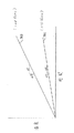
デューティ・サイクルはt2-t1の期間中、0.25に保持される(1001)。t2-t1の正確な量は、定着器システムの熱的質量および輸送遅れによって変わるので、各用途毎に決定しなければならない。なお、試験中のプリンタの定着器システムにおいては、20秒とした。温度勾配(ΔT/Δt)は、時間間隔Δtおよび定着器温度ΔTから決まる(1002)。この温度勾配から電源電圧を求めることができる(1003)。ちなみに、図2の線701は110Vrmsの入力電圧に対応し、線702は220Vrmsの入力電圧に対応する。
【0015】
定着器の安全且つ確実な動作を確保するには、その電源電圧に基づく最大デューティ・サイクル(DMAX)を割り当てる(1004)。好適実施例においては、電源電圧が110Vrmsであれば、DMAXを1.0に、電源電圧が127Vrmsであれば、DMAXを0.75に、電源電圧が220Vrmsであれば、DMAXを0.25に、経験的に決定した。デューティ・サイクルがまだDMAXになっていなければ(1005)、それを1秒の期間t3にわたりDMAXまで直線的に増大させる(1006)。図3を参照すると、220Vrmsの入力電圧を与えると、t2までにDMAXに到達している。それより低い電圧で動作するシステムでは、デューティ・サイクルは線802で示すように0.25からDMAXまで増大している。
【0016】
デューティ・サイクルがDMAXに到達すると、正しい温度を維持するための温度制御プロセスが呼び出される。当業者が本発明を理解するには、このプロセスを詳細に説明する必要はないであろう。
【0017】
再び図1を参照して、印刷が完了すると、定着器はDMAXを50%だけ減らしてアイドリング・モードに入る(1008)。プリンタはアイドリング・モードを出て(1010)、印刷モードまたは省電力モードに入る。プリンタが省電力モードに入ると (1011)、定着器への電力がデューティ・サイクルを0に設定することにより遮断される(1013)。省電力モードまたはアイドリング・モードを出るには、DMAXを、1004で決定したその元の値にリセットしなければならない(1012)。
【0018】
温度制御システムの構成およびパルス幅変調器401、電源、電源電子装置301、定着器システム302、および温度制御システム400を示す物理的構成要素の構成の図を図4に示す。図4の温度制御システムは、唯一のフィードバック量である定着器302の温度を使用している。これにより、制御システム400を実現するのに極めて低コストのマイクロプロセッサ(図5の4001)を使用できるので、最低コストの装置が得られる。定着器の温度はAD変換器4000によりサンプルされ、温度制御プログラム1007を実行するマイクロプロセッサ4001により使用される。温度制御プログラム1007の結果はDA変換器4002に供給される。DA変換器4002からのアナログ出力はPWM401を制御する。当業者はPWMをマイクロ制御器4001に設置し 、それによりDA変換器4002およびPWM401の必要性を省くことができることを理解するであろう。
【0019】
これまで、デューティ・サイクルを直接変えることにより加熱素子への入力電力を制御することに関して説明してきたが、当業者は同じ仕事を、たとえば、Kaiedaの位相制御またはBarretのIHCの数を変更することにより行うことができることを理解するであろう。
【0020】
本発明の好適実施例を例示し且つその形態を説明してきたが、当業者には、本発明の精神からまたは付記した「特許請求の範囲」の範囲から逸脱することなく前記実施例に種々の修正を加え得ることが容易に明らかである。
【0021】
〔実施態様〕
なお、本発明の実施態様の例を以下に示す。
【0022】
〔実施態様1〕 電源の電圧値を求める装置であって、
加熱素子(302)と、
前記加熱素子(302)の温度を検出する手段と、
前記電源から所定の電力を前記加熱素子(302)に与えるための制御器手段(400)であって、前記検出手段により前記加熱素子(302)の温度変化の速度を測定する制御器手段(400)と
を備え、前記電圧値が前記温度変化の速度に比例していることを利用して電圧値を求めることを特徴とする装置。
【0023】
〔実施態様2〕 前記制御器手段(400)は、電力を所定期間中に前記所定の電力まで滑らかに増大させることを特徴とする、実施態様1に記載の装置。
【0024】
〔実施態様3〕 前記制御器手段(400)は更に、前記加熱素子(302)の温度を動作温度に維持することを特徴とする、実施態様1または実施態様2に記載の装置。
【0025】
〔実施態様4〕 前記制御器手段(400)は、前記加熱素子(302)の温度を最大電圧に対する最大温度より低い温度に維持するように、前記所定の電力を選定することを特徴とする、実施態様1ないし実施態様3のいずれか一項に記載の装置。
【0026】
〔実施態様5〕 電源と、
加熱素子(302)と、
前記加熱素子(302)の温度を検出する手段と、
前記電源から前記加熱素子(302)に送られる電力の量を制御するための制御器手段(400)であって、前記電源からの有効な所定の電力まで電力を滑らかに増大させ、前記検出手段により前記加熱素子(302)の前記温度の変化の速度を測定する制御器手段(400)と
を備え、前記制御器手段(400)が前記変化の速度を利用して前記電源の電圧値を求める装置。
【0027】
〔実施態様6〕 前記制御器手段(400)は更に、前記加熱素子(302)の前記温度を動作温度に維持することを特徴とする、実施態様5に記載の装置。
【0028】
〔実施態様7〕 前記制御器手段(400)は、前記加熱素子(302)の前記温度を最大電圧に対する最大温度より低い温度に維持するように、前記所定の電力を選定することを特徴とする、実施態様5または実施態様6に記載の装置。
【0029】
〔実施態様8〕 画像生成装置用電源の電圧値を求める方法であって、
電源からの所定の電力を加熱素子(302)に伝えるステップ(1000、1001)と、
前記加熱素子(302)の温度変化の速度を測定するステップ(1002)と、
前記温度変化の速度を利用して前記電圧値を求めるステップと
を設けて成る方法。
【0030】
〔実施態様9〕 電力を所定期間中に前記所定の電力まで滑らかに増大させるステップをさらに設けたことを特徴とする、実施態様8記載の装置。
【0031】
〔実施態様10〕 前記所定期間は1秒以上であることを特徴とする、実施態様2ないし実施態様4のいずれか一項または実施態様9に記載の方法。
【0032】
【発明の効果】
以上詳細に説明したように、本発明によれば、熱出力を有する電子装置において、あらゆる電源電圧に対応できるようにする機能を提供できる。従って、各地域毎の電源事情に左右されることがないので、交換部品として各電源電圧に対応するように種々のものを用意しておく必要がなく、設計、生産、在庫コストを大幅に削減することができる。
【図面の簡単な説明】
【図1】本発明の制御プロセス全体を示す流れ図である。
【図2】入力電圧が異なるために温度勾配が異なることを示す図である。
【図3】本発明による装置における、入力電力のデューティ・サイクルの時間的変化を示す図である。
【図4】本発明に使用する定着温度制御システム全体のブロック図である。
【図5】図4の制御器のブロック図である。
【符号の説明】
301:電力電子装置
302:定着器
400:温度制御システム
401:パルス幅変調器[0001]
BACKGROUND OF THE INVENTION
The present invention generally relates to power control systems, and more particularly to a method and apparatus for determining a power supply voltage value supplied to a heating resistance element.
[0002]
[Prior art]
From around 1984, low-cost personal laser printers were realized and sold. All dry electrophotographic copiers and printers develop using dry toner. A normal toner is composed of a styrene acrylic resin, a pigment (usually carbon black), and a charge control dye that imparts a desired triboelectric chargeability for developing an electrostatic latent image on the toner. Styrene acrylic resins are thermoplastic resins that can be melted and fixed to a desired medium, usually paper.
[0003]
A typical fuser system of an electrophotographic printer or copier is a two-part system that melts toner and physically fuses the melted thermoplastic resin to the medium as the printed medium carrying the developed image passes between them. A heating platen roller is provided. Heating is accomplished by placing a high power tungsten filament quartz lamp inside the hollow platen roller.
[0004]
The heating element of the fuser system provides sufficient heat to properly fix the toner to the media. The fuser system must compensate for dramatic changes in relative humidity as well as changes in various media types and ambient temperature. The change in relative humidity greatly affects the fuser system because both the print medium and the toner itself are hygroscopic. When the relative humidity is high, the media and toner contain moisture that evaporates during the fixing process. Thus, the amount of energy available to melt the toner for fixing to the media is reduced by the amount spent on its evaporation action. Therefore, the fuser system must meet a variety of media requirements as well as very diverse environmental conditions.
[0005]
Currently, most printer and copier fuser systems and their temperature control systems are not designed to compensate for changes in various media types or relative humidity. Conventional fuser systems are designed with heating elements that can provide enough heat to handle all foreseeable media and relative humidity conditions, and the resulting power quality is poor. Little or no interest. Some relatively new printers use relative humidity sensors to adjust print quality and use optical sensors to distinguish between paper and overhead projection transparency. These additional sensors are added to the printing mechanism to improve image quality, but besides improving temperature regulation, they can also be used in fuser control systems to improve the overall power quality of the printing system. it can.
[0006]
There are many reasons for more aggressive and intelligent control of an electrophotographic printer or copier fuser system. For example, if intelligent control is performed, a universal fixing device that can be shipped to any market in the world regardless of the power system can be obtained. Such a universal fuser has the attractive advantage that only one part is required for both manufacturing and field service replacement. This frees manufacturers from the burden of manufacturing 110 VAC and 220 VAC printers. When the need to stock two types of service parts is eliminated, the product distribution center needs only one product that can be shipped to any country in the world without having to reconfigure. In addition, the burden of work on sales, delivery, and manufacturing scheduling is reduced. As can be expected, the production of a single product for global consumption is a significant economic advantage.
[0007]
[Problems to be solved by the invention]
Considering a dry electrophotographic fuser system that operates worldwide, the system must be able to operate satisfactorily with an AC power system that supplies from 90 Vrms to 240 Vrms at frequencies from 50 Hz to 60 Hz. The fuser system must be heated as quickly as possible from ambient room temperature to operating temperature, while the flicker shown as its power consumption level must be very small. The fuser system, when combined with the rest of the power electronics of the electrophotographic printer, must meet International Electrotechnical Commission (IEC) standards for current harmonics and flicker IEC 555-2 and IEC 555-3 . The printer or copier must pass the Federal Communications Commission (FCC) Class B standard for power line conducted emissions and radiated emissions. In addition, the printer must pass CISPR B requirements for power line conducted emissions and radiated emissions. Finally, the printer should not have the disadvantage of generating excessive multitone or single tone sound in the human audible range in the office environment. The fuser system must be able to be switched to a reduced power mode or a cut-off mode for energy saving as suggested by the Energy Star Program of the EPA (Environmental Protection Agency). The absolute cost of any additional electronic devices will be greater than the cost of not having to stock a large number of 110 VAC and 220 VAC models.
[0008]
US Pat. No. 5,483,149 to Barret (hereinafter referred to as Barret) shows that a universal fuser can be obtained by using an improved IHC (integral half cycle) power controller. Does not solve the flicker problem. The method taught by Barret shows that, besides suffering some flicker problems, the AC power system is subject to current splitting frequency. At present, there is no provision regarding the content of AC current frequency division. It is sufficient to note that AC current splitting is not necessary for the power grid, and that AC current splitting in the range of 4 Hz to 20 Hz contributes significantly to the flicker level exhibited by the electrical device. But Barret needs to know the input voltage.
[0009]
Other methods such as phase control where the triac's conduction angle increases relatively slowly meet the IEC 555-3 specification for flicker, but the universal fuser system does not pass the IEC 555-2 specification for current harmonics. It shows that it is obtained. Triac switching phase control also does not pass the specification of conducted power line emission unless an additional additional power filter is added. U.S. Pat. No. 4,928,055 issued to Kaieda et al. (Hereinafter referred to as Kaieda) teaches a fuser power control system based on phase delay switching triac control of an AC heating system. Kaieda is interested only in power control, but as taught in Japanese Patent Application No. 9-206510 “Flicker Reduction Method in Printing Equipment”, the correct temperature control algorithm design makes the solution a universal fuser. The flicker problem can be greatly reduced. However, this solution also requires zero-cross information for correct TRIAC switching control in addition to detailed voltage magnitude information and associated costs. In addition to receiving excessive current harmonics, this system also carries a large amount of conducted emissions on the power grid.
[0010]
[Means for Solving the Problems]
The present invention provides an apparatus for determining an input voltage value from a power source. The apparatus includes a heating element and a temperature sensor that monitors the temperature of the heating element. The input voltage value can be obtained by applying effective predetermined power from the power source to the heating element and measuring the rate of change in temperature of the heating element at that time.
[0011]
Once the input voltage value is determined, a temperature control process is performed to maintain the temperature of the heating element.
[0012]
【Example】
The present invention can be better understood by considering the following detailed description in conjunction with the drawings.
[0013]
The invention is not limited to the specific embodiments illustrated herein. A preferred embodiment of the overall control system will be described with reference to FIGS. To obtain safety and product reliability, the input voltage must be determined before the control system begins to control the fuser system. To do this, the duty cycle of the power controller is increased linearly from 0 to 0.25 over the period of t 1 (1000). The time to increase can be short or long, but the preferred embodiment uses t 1 = 1s. This final value of 0.25 is related to the maximum duty cycle at the highest specific input voltage of 220 Vrms. Other fuser systems may have other values related to the maximum voltage. In particular, the power control device of the preferred embodiment is
P = V 2 d / R
Shows the power usage. Where d represents the duty cycle. Thus, limiting the duty cycle (d) to 0.25, the maximum power drawn from the 220 Vrms power supply is less than the amount of power drawn from the 110 Vrms power supply when d = 1.
[0014]
The duty cycle is held at 0.25 during the period t 2 -t 1 (1001). The exact amount of t 2 -t 1 depends on the thermal mass of the fuser system and the transport delay and must be determined for each application. In the fixing system of the printer under test, 20 seconds was used. The temperature gradient (ΔT / Δt) is determined from the time interval Δt and the fuser temperature ΔT (1002). The power supply voltage can be obtained from this temperature gradient (1003). Incidentally, the
[0015]
To ensure safe and reliable operation of the fuser, a maximum duty cycle (D MAX ) based on its power supply voltage is assigned (1004). In the preferred embodiment, if the power supply voltage 110Vrms, the 1.0 D MAX, if the power supply voltage 127Vrms, the D MAX 0.75, if the
[0016]
When the duty cycle reaches D MAX , a temperature control process is invoked to maintain the correct temperature. It will not be necessary to describe this process in detail for those skilled in the art to understand the present invention.
[0017]
Referring again to FIG. 1, when printing is complete, the fuser reduces DMAX by 50% and enters idle mode (1008). The printer exits idle mode (1010) and enters print mode or power saving mode. When the printer enters power saving mode (1011), the power to the fuser is cut off by setting the duty cycle to 0 (1013). To exit the power saving or idling mode, D MAX must be reset to its original value determined at 1004 (1012).
[0018]
FIG. 4 shows a diagram of the configuration of the temperature control system and the physical components showing the
[0019]
So far, we have described with respect to controlling the input power to the heating element by directly changing the duty cycle, but those skilled in the art do the same job, for example, changing the number of Kaieda phase controls or Barret IHCs. Will understand that can be done.
[0020]
While the preferred embodiment of the invention has been illustrated and described in terms of its form, those skilled in the art will appreciate that various embodiments of the invention can be made without departing from the spirit of the invention or from the scope of the appended claims. It is readily apparent that modifications can be made.
[0021]
Embodiment
Examples of embodiments of the present invention are shown below.
[0022]
[Embodiment 1] An apparatus for determining a voltage value of a power source,
A heating element (302);
Means for detecting the temperature of the heating element (302);
Controller means (400) for applying predetermined power from the power source to the heating element (302), wherein the detecting means measures the temperature change rate of the heating element (302) by the detecting means (400). And the voltage value is obtained by utilizing the fact that the voltage value is proportional to the speed of the temperature change.
[0023]
Embodiment 2 The apparatus according to embodiment 1, characterized in that the controller means (400) smoothly increases power to the predetermined power during a predetermined period.
[0024]
Embodiment 3 The apparatus according to embodiment 1 or embodiment 2, wherein the controller means (400) further maintains the temperature of the heating element (302) at an operating temperature.
[0025]
[Embodiment 4] The controller means (400) is characterized in that the predetermined power is selected so that the temperature of the heating element (302) is maintained at a temperature lower than a maximum temperature with respect to a maximum voltage. Embodiment 4. The apparatus according to any one of embodiments 1 to 3.
[0026]
[Embodiment 5] a power source;
A heating element (302);
Means for detecting the temperature of the heating element (302);
Controller means (400) for controlling the amount of power sent from the power source to the heating element (302), smoothly increasing the power to an effective predetermined power from the power source, and the detecting means Controller means (400) for measuring the rate of change of the temperature of the heating element (302) by means of the controller means (400) using the rate of change to determine the voltage value of the power supply. apparatus.
[0027]
Embodiment 6 The apparatus of embodiment 5, wherein the controller means (400) further maintains the temperature of the heating element (302) at an operating temperature.
[0028]
[Embodiment 7] The controller means (400) selects the predetermined power so as to maintain the temperature of the heating element (302) at a temperature lower than a maximum temperature with respect to a maximum voltage. Embodiment 7. A device according to embodiment 5 or embodiment 6.
[0029]
[Embodiment 8] A method for obtaining a voltage value of a power supply for an image generating apparatus, comprising:
Transmitting predetermined power from the power source to the heating element (302) (1000, 1001);
Measuring the rate of temperature change of the heating element (302) (1002);
And a step of obtaining the voltage value using the speed of the temperature change.
[0030]
[Embodiment 9] The apparatus according to Embodiment 8, further comprising the step of smoothly increasing power to the predetermined power during a predetermined period.
[0031]
[Embodiment 10] The method according to any one of Embodiments 2 to 4, or Embodiment 9, wherein the predetermined period is 1 second or longer.
[0032]
【The invention's effect】
As described above in detail, according to the present invention, it is possible to provide a function that allows an electronic device having a thermal output to cope with any power supply voltage. Therefore, since it is not affected by the power supply situation in each region, it is not necessary to prepare various parts to correspond to each power supply voltage as a replacement part, greatly reducing design, production, and inventory costs. can do.
[Brief description of the drawings]
FIG. 1 is a flowchart showing the entire control process of the present invention.
FIG. 2 is a diagram showing a difference in temperature gradient due to a difference in input voltage.
FIG. 3 is a diagram showing the time variation of the duty cycle of the input power in the device according to the invention.
FIG. 4 is a block diagram of the entire fixing temperature control system used in the present invention.
FIG. 5 is a block diagram of the controller of FIG. 4;
[Explanation of symbols]
301: Power electronics
302: Fixing device
400: Temperature control system
401: Pulse width modulator
Claims (10)
加熱素子(302)と、
前記加熱素子(302)の温度を検出する検出手段と、
前記電源からの電力の一部を前記加熱素子(302)に供給し、前記検出手段を用いて前記加熱素子(302)の温度の変化速度を測定し、該変化速度に比例した前記電圧を判定する制御手段(400)と
からなる装置。A device for determining the voltage of a power supply,
A heating element (302);
Detection means for detecting the temperature of the heating element (302);
A part of the electric power from the power source is supplied to the heating element (302), the change rate of the temperature of the heating element (302) is measured using the detection means, and the voltage proportional to the change rate is determined. And a control means (400).
加熱素子(302)と、
前記加熱素子(302)の温度を検出する検出手段と、
前記電源から前記加熱素子(302)に送られる電力の大きさを制御する制御手段(400)であって、前記電力を電源から得られる電力の一部まで滑らかに増加させ、前記検出手段を用いて前記加熱素子(302)の温度の変化速度を検出測定し、該変化速度を用いて前記電源の電圧を判定する制御手段(400)と
からなる装置。Power supply,
A heating element (302);
Detection means for detecting the temperature of the heating element (302);
Control means (400) for controlling the amount of power sent from the power source to the heating element (302), wherein the power is smoothly increased to a part of the power obtained from the power source, and the detection means is used. And a control means (400) for detecting and measuring the temperature change rate of the heating element (302) and determining the voltage of the power source using the change rate.
前記電源からの電力の一部を加熱素子(302)に送るステップ(1000、1001)と、
前記加熱素子(302)の温度の変化速度を測定するステップ(1002)と、
前記変化速度を用いて前記電圧を判定するステップと
からなる方法。A method of determining a voltage of a power supply for an image generating device,
Sending (1000, 1001) a portion of the power from the power source to the heating element (302);
Measuring a temperature change rate of the heating element (302) (1002);
Determining the voltage using the rate of change.
Applications Claiming Priority (2)
| Application Number | Priority Date | Filing Date | Title |
|---|---|---|---|
| US704,217 | 1991-05-22 | ||
| US08/704,217 US6710309B1 (en) | 1996-08-23 | 1996-08-23 | Use of the temperature gradient to determine the source voltage |
Publications (2)
| Publication Number | Publication Date |
|---|---|
| JPH1090310A JPH1090310A (en) | 1998-04-10 |
| JP4212668B2 true JP4212668B2 (en) | 2009-01-21 |
Family
ID=24828577
Family Applications (1)
| Application Number | Title | Priority Date | Filing Date |
|---|---|---|---|
| JP22350497A Expired - Fee Related JP4212668B2 (en) | 1996-08-23 | 1997-08-20 | Apparatus and method for determining power supply voltage value |
Country Status (2)
| Country | Link |
|---|---|
| US (1) | US6710309B1 (en) |
| JP (1) | JP4212668B2 (en) |
Families Citing this family (6)
| Publication number | Priority date | Publication date | Assignee | Title |
|---|---|---|---|---|
| KR100608020B1 (en) | 2004-12-23 | 2006-08-02 | 삼성전자주식회사 | Fixing apparatus included in electrophotographic image forming apparatus and temperature controlling method of fusing apparatus and recording medium storing computer program implementing the temperature controlling method |
| US8577233B2 (en) * | 2008-04-10 | 2013-11-05 | Hewlett-Packard Development Company, L.P. | System and method for selecting color tables for a color printer |
| EP3574375A4 (en) * | 2017-01-25 | 2020-09-02 | Hewlett-Packard Development Company, L.P. | Determining media weight based on input voltage estimate |
| WO2018182735A1 (en) * | 2017-03-31 | 2018-10-04 | Hewlett-Packard Development Company, L.P. | Simultaneous use of phase control and integral half cycle (ihc) control |
| US20220050413A1 (en) * | 2019-04-30 | 2022-02-17 | Hewlett-Packard Development Company, L.P. | Control of printer heating elements based on input voltages |
| EP4195873A1 (en) * | 2021-12-07 | 2023-06-14 | Shanghai Kohler Electronics, Ltd. | Heating seat ring voltage self-adaption method, electronic device, and storage medium |
Family Cites Families (8)
| Publication number | Priority date | Publication date | Assignee | Title |
|---|---|---|---|---|
| US3863049A (en) * | 1972-05-31 | 1975-01-28 | Union Carbide Corp | Temperature control apparatus for a centrifugal-type chemistry analyzer |
| US4432211A (en) * | 1980-11-17 | 1984-02-21 | Hitachi, Ltd. | Defrosting apparatus |
| AU7972982A (en) * | 1981-01-29 | 1982-08-05 | Varian Techtron Pty. Ltd. | Voltage feedback temperature control |
| US4549073A (en) * | 1981-11-06 | 1985-10-22 | Oximetrix, Inc. | Current controller for resistive heating element |
| US4929930A (en) * | 1988-10-24 | 1990-05-29 | Process Technology Inc. | Liquid level controller utilizing the rate of change of a thermocouple |
| JPH02166490A (en) | 1988-11-25 | 1990-06-27 | Nippon Kentek Kaisha Ltd | Control circuit for heat fixing apparatus |
| JP2650998B2 (en) * | 1989-01-07 | 1997-09-10 | 古河電気工業株式会社 | Optical fiber for detecting liquid, gas, etc. |
| US5483149A (en) | 1993-10-28 | 1996-01-09 | Hewlett-Packard Company | Resistive heating control system and method that is functional over a wide supply voltage range |
-
1996
- 1996-08-23 US US08/704,217 patent/US6710309B1/en not_active Expired - Fee Related
-
1997
- 1997-08-20 JP JP22350497A patent/JP4212668B2/en not_active Expired - Fee Related
Also Published As
| Publication number | Publication date |
|---|---|
| JPH1090310A (en) | 1998-04-10 |
| US6710309B1 (en) | 2004-03-23 |
Similar Documents
| Publication | Publication Date | Title |
|---|---|---|
| US6018140A (en) | Image forming apparatus, control method for controlling the same and temperature control apparatus | |
| CA1159877A (en) | Charge density control | |
| US7212760B2 (en) | Image forming apparatus performing improved fixing temperature control | |
| JP4212668B2 (en) | Apparatus and method for determining power supply voltage value | |
| JP3181043B2 (en) | Method of controlling power application to multiple heating elements and electrophotographic printing system | |
| US6018151A (en) | Predictive fusing system for use in electrophotographic printers and copiers | |
| US6901226B2 (en) | Power control for a xerographic fusing apparatus | |
| JPH1091043A (en) | Method for reducing flicker in printer | |
| JPH0267579A (en) | Image forming device | |
| US6097006A (en) | Fixing unit for use in image forming device | |
| JP2002051467A (en) | Printer-fixing device heater controller | |
| JP4539453B2 (en) | HEATER CONTROL DEVICE, IMAGE FORMING DEVICE, HEATER CONTROL METHOD, AND PROGRAM | |
| JP2004233745A (en) | Fixing heater controller and image forming apparatus | |
| US20080193155A1 (en) | Image forming apparatus and method of controlling a temperature of a fixing unit thereof | |
| JP2006164615A (en) | Heater power control method, and image forming apparatus | |
| JPH10149054A (en) | Controlling method for operation of heated fixing material | |
| JP4386481B2 (en) | Power supply control device for the load of the playback device, especially the fixed unit | |
| US20070097577A1 (en) | Electric power supplying apparatus and image forming apparatus | |
| JPH1173057A (en) | Image forming device, image forming method and storage medium storing image forming procedure | |
| JP3395812B2 (en) | Temperature control method in fixing device | |
| JP3315495B2 (en) | Image forming device | |
| JP2002278350A (en) | Heating device and image forming device | |
| JPH09127825A (en) | Controller for fixing unit | |
| JP3423555B2 (en) | Fixing device | |
| JP2001237048A (en) | Heating device and image forming device |
Legal Events
| Date | Code | Title | Description |
|---|---|---|---|
| A521 | Written amendment |
Free format text: JAPANESE INTERMEDIATE CODE: A523 Effective date: 20040820 |
|
| A621 | Written request for application examination |
Free format text: JAPANESE INTERMEDIATE CODE: A621 Effective date: 20040820 |
|
| A131 | Notification of reasons for refusal |
Free format text: JAPANESE INTERMEDIATE CODE: A131 Effective date: 20070918 |
|
| A601 | Written request for extension of time |
Free format text: JAPANESE INTERMEDIATE CODE: A601 Effective date: 20071218 |
|
| A602 | Written permission of extension of time |
Free format text: JAPANESE INTERMEDIATE CODE: A602 Effective date: 20071221 |
|
| TRDD | Decision of grant or rejection written | ||
| A01 | Written decision to grant a patent or to grant a registration (utility model) |
Free format text: JAPANESE INTERMEDIATE CODE: A01 Effective date: 20081007 |
|
| A01 | Written decision to grant a patent or to grant a registration (utility model) |
Free format text: JAPANESE INTERMEDIATE CODE: A01 |
|
| A61 | First payment of annual fees (during grant procedure) |
Free format text: JAPANESE INTERMEDIATE CODE: A61 Effective date: 20081029 |
|
| FPAY | Renewal fee payment (event date is renewal date of database) |
Free format text: PAYMENT UNTIL: 20111107 Year of fee payment: 3 |
|
| R150 | Certificate of patent or registration of utility model |
Free format text: JAPANESE INTERMEDIATE CODE: R150 |
|
| FPAY | Renewal fee payment (event date is renewal date of database) |
Free format text: PAYMENT UNTIL: 20121107 Year of fee payment: 4 |
|
| FPAY | Renewal fee payment (event date is renewal date of database) |
Free format text: PAYMENT UNTIL: 20121107 Year of fee payment: 4 |
|
| S111 | Request for change of ownership or part of ownership |
Free format text: JAPANESE INTERMEDIATE CODE: R313113 |
|
| FPAY | Renewal fee payment (event date is renewal date of database) |
Free format text: PAYMENT UNTIL: 20121107 Year of fee payment: 4 |
|
| R350 | Written notification of registration of transfer |
Free format text: JAPANESE INTERMEDIATE CODE: R350 |
|
| FPAY | Renewal fee payment (event date is renewal date of database) |
Free format text: PAYMENT UNTIL: 20121107 Year of fee payment: 4 |
|
| FPAY | Renewal fee payment (event date is renewal date of database) |
Free format text: PAYMENT UNTIL: 20131107 Year of fee payment: 5 |
|
| LAPS | Cancellation because of no payment of annual fees |