JP4211212B2 - Shutter mechanism and portable device - Google Patents
Shutter mechanism and portable device Download PDFInfo
- Publication number
- JP4211212B2 JP4211212B2 JP2000300333A JP2000300333A JP4211212B2 JP 4211212 B2 JP4211212 B2 JP 4211212B2 JP 2000300333 A JP2000300333 A JP 2000300333A JP 2000300333 A JP2000300333 A JP 2000300333A JP 4211212 B2 JP4211212 B2 JP 4211212B2
- Authority
- JP
- Japan
- Prior art keywords
- shutter
- shutter member
- guide groove
- operation unit
- state
- Prior art date
- Legal status (The legal status is an assumption and is not a legal conclusion. Google has not performed a legal analysis and makes no representation as to the accuracy of the status listed.)
- Expired - Fee Related
Links
Images


Description
【0001】
【発明の属する技術分野】
本発明は、機器の操作部を開閉するシャッター機構及びそのシャッター機構を備えた携帯用機器に関する。
【0002】
【従来の技術】
例えば携帯型の音響機器においては、操作部のスイッチの誤操作を防止するために、操作部を開閉するシャッターを設け、このシャッターによって操作部を閉じることで機械的に外力を遮断するようにしたいわゆるメカニカルホールドシャッター機構を採用したものがある。
【0003】
従来のこの種のシャッター機構の一例を図9に示す。図において41は例えば携帯型のカセットプレーヤーを示し、このカセットプレーヤー41の筺体42の一面に設けられた操作部43を開閉するためにシャッター機構44が設けられている。
【0004】
操作部43には、再生スイッチ43a、停止スイッチ43b、巻戻しスイッチ43c、早送りスイッチ43dが配置されており、この操作部43をシャッター45の移動操作によって開閉するようにしている。
【0005】
即ち図9Aはシャッター45によって操作部が閉じられた状態を示し、この状態では操作部43に対する外力がシャッター45によって機械的に遮断されることにより、操作部43の各スイッチの誤操作つまりこれらのスイッチが不用意に押されることが防止される。
【0006】
そしてこの状態からシャッター45を移動させて図9Bに示す如く操作部43を開くことにより、操作部43の各スイッチを自由に操作できる状態となる。
【0007】
このシャッター機構44の動作機構部の構造を図10に示す。尚、この図10のA,Bは夫々図9のA,Bと対応しており、即ち図10Aはシャッターによって操作部が閉じられた状態、Bは開かれた状態である。
【0008】
この図10はシャッター機構44を筺体の裏側から見たもので、46は筺体に固定される固定板、47はこの固定板46に対し直線移動可能に取り付けられたスライド板である。このスライド板47は連結部48を介してシャッター45と連結されており、即ちこのスライド板47はシャッター45と一体に直線移動されるようになっている。
【0009】
固定板46の端部とスライド板47の端部との間には、ねじりコイルばねによりなるトグルばね49が取り付けれており、このトグルばね49のばね力によってスライド板47即ちシャッター45はその移動操作時にトグル動作が行なわれ、操作部43を閉じた位置と開いた位置とで固定状態に保持される構造となっている。
【0010】
【発明が解決しようとする課題】
このような従来のシャッター機構には、次のような課題がある。
即ち従来のシャッター機構は、シャッターを平面的に直線移動させるだけで操作部を開閉する構造であるため、シャッターの移動操作時にはその移動距離(ストローク)が長く感じられ、操作性が良いものとは言えない。
【0011】
本発明はこのような課題を解決するためになされたもので、良好な操作感の得られるシャッター機構を提供することを目的としている。
【0012】
【課題を解決するための手段】
上記の目的を達成するものとして本発明は、
機器の操作部を開閉するシャッターを有するシャッター機構において、
シャッターは、
略L字型に形成され、且つ、機器側に設けられたガイド溝に沿って回転しながら移動するように操作される回動シャッター部材と、
この回動シャッター部材に連結され、この回動シャッター部材と連動してガイド溝に沿って平面的に直線移動されると共に平板形状を有する直動シャッター部材と、
により構成され、
直動シャッター部材には、シャッターが操作部を閉じた位置と開いた位置の二位置ある状態において機器側の係合部と係合しシャッターをその位置で固定状態に保持する板ばね部材が取り付けられてなる構造としたものである。
【0013】
このように構成される本発明のシャッター機構では、シャッターは回転移動と平面的な直線移動とが複合化した動きで移動操作されるので、見かけ上の移動距離が短く感じられ、その結果シャッターの良好な操作感が得られる。
【0014】
【発明の実施の形態】
以下、図面を参照しながら本発明の実施の形態例について詳細に説明する。
図1及び図2は本発明のシャッター機構が適用される音響機器の一例として携帯型のカセットプレーヤーを示しており、図1はその斜視図、図2は裏返して見た斜視図である。
【0015】
このカセットプレーヤー1はコンパクトテープカセットを記録媒体として使用し、充電池または乾電池で駆動するテープカセットのA/B両面を再生可能なオートリバース機能付きの携帯用機器である。
2はカセットプレーヤーの機器本体、3はその筺体、4は蓋体を示している。蓋体4は機器本体2に対し開閉可能となされており、通常の状態ではこの蓋体4は閉じ状態でロックされ、操作つまみ5を移動操作することによって蓋体4のロックを解除して蓋体4を開いた状態でテープカセットを挿入して装着する。
6はヘッドホン接続端子であり、この接続端子6にリモートコントローラー付きヘッドホン装置を接続して使用するものである。
【0016】
このカセットプレーヤー1においては、機器本体2の側面に操作部7が設けられており、この操作部7は図1及び図2に示す状態では本発明によるシャッター機構10によって閉じられている。
【0017】
図3はこの操作部付近の拡大図である。
機器本体2の側面に設けられる操作部7は、いわゆるジョグスイッチ8を有してなり、即ちこのジョグスイッチ8はこれを押す操作と回転させる操作によって各種動作が行なわれるものである。例えば、図4に示す如くジョグスイッチ8を中立位置で矢印a方向に押すと再生/停止動作が交互に行なわれ、またジョグスイッチ8を矢印b方向に回転させると巻き戻し、これと反対の矢印c方向に回転させると早送り動作が行なわれる。
【0018】
そしてこの操作部7において、ジョグスイッチ8の誤操作を防止するために本発明によるシャッター機構10が設けられている。
【0019】
このシャッター機構10においては、機器本体の筺体3の稜線部を跨ぐ平板面3aと側板面3bにわたってL字形の体裁部品である飾り枠11が取り付けられ、この飾り枠11の枠内を移動するようにシャッター12が設けられている。
【0020】
このシャッター12は二部品即ち回動シャッター部材13と直動シャッター部材14とにより構成されている。
回動シャッター部材13は操作部7のジョグスイッチ8を覆うリッド形状を有し、筺体3の側板面3bから平板面3aにかけて回転しながら移動するように操作されるものである。
一方、直動シャッター部材14は平板形状を有し、回動シャッター部材13と連結されてこの回動シャッター部材13と連動して筺体3の平板面3aに沿って移動されるものである。
【0021】
図3Aはシャッター12によって操作部7が閉じられた状態を示し、この状態では操作部7に対する外力がシャッター12によって機械的に遮断されることにより、操作部7のジョグスイッチ8の誤操作つまりこのジョグスイッチ8が不用意に操作されることが防止される。
【0022】
そしてこの状態から回動シャッター部材13に指を掛けてシャッター12を移動させ、図3Bに示す如く操作部7を開くことにより、ジョグスイッチ8を自由に操作できる状態となる。
尚、このシャッターの移動操作において回動シャッター部材13に指を掛け易いように、回動シャッター部材13の角部にはギザ13bが形成されている。
【0023】
このシャッター機構10のさらに詳細な構造を図5以下で説明する。
【0024】
図5は体裁部品である飾り枠11の取り付け構造を裏側から見た状態で示している。
ここで飾り枠11は樹脂成形品であり、これをアルミニウム等の軽金属製の筺体3に取り付けるものである。
【0025】
飾り枠11は筺体3の平板面3aに対応する水平枠部11aと、側板面3bに対応する垂直枠部11bとによりなるL字形に屈曲した枠部材であり、さらに垂直枠部11bの裏側には後述するガイド溝22を形成するブロック部11cが一体に形成されている。
【0026】
この飾り枠11の水平枠部11aの裏面側には複数の溶着突起15が突設され、また垂直枠部11bの先端には周縁に溝16が形成されている。
一方、筺体3はその平板面3aにおいて、飾り枠11の枠内に対応する部分即ちシャッター12の配置部分が表面から一段引込んだ段面部17となされ、この段面部17の周囲には飾り枠11の溶着突起15と対応する通し穴18が形成されており、さらに段面部17の前方から側板面3bにかけての部分にはこの部分を大きく切り欠いた開放穴19が形成されている。
【0027】
そして飾り枠11の水平枠部11aの溶着突起15を筺体3の通し穴18に通すと同時に垂直枠部11bの溝16を筺体3の開放穴19の縁部に係合させ、その状態で溶着突起15の先端部に超音波等で熱を加えてその部分を溶融させてかしめる熱溶着の手法により、飾り枠11を筺体3に固定する。
【0028】
図6は飾り枠11に設けられるガイド溝22の構造を示している。
このガイド溝(カム溝)22は飾り枠11の左右両側に対称的に形成されるもので、これに沿ってシャッター12が移動されるようになっている。
このガイド溝22は前方の円弧状の曲線部(回転動作範囲)22aと、これに連続する後方の直線部(直線動作範囲)22bとにより形成されている。
【0029】
ここで曲線部22aは、飾り枠11の水平枠部11aから垂直枠部11bにかけての部分とブロック部11cとの間に形成されており、また直線部22bは、曲線部22aに続く前方の一部分が水平枠部11aとブロック部11cとの間に形成され、これより後方の大部分が水平枠部11aと筺体3の段面部17との間で形成されている。
【0030】
図7はシャッター12の構造を裏返し状態で示している。
このシャッター12は前述した如く回動シャッター部材13と直動シャッター部材14の二部品によりなり、これらは何れも樹脂成形品である。
回動シャッター部材13は、その前部側面から外側に突出するスライドピン24と、後方に延出される脚部13aの先端から外側に突出するスライドピン25とを夫々左右両側に対称的に有し、図8に示すようにこの前後のスライドピン24,25が飾り枠11のガイド溝22の曲線部22aから直線部22bに沿って移動可能に係合されて組み込まれる。
一方、直動シャッター部材14は、その側面から外側に突出するスライド片26を左右両側に有し、このスライド片26がガイド溝22の直線部22bに沿って移動可能に係合されて組み込まれる。
【0031】
また直動シャッター部材14の前部両側には連結凹部27が形成されており、この連結凹部27に回動シャッター部材14の後方のスライドピン25が係合し、これによって回動シャッター部材13と直動シャッター部材14とが連結される。
尚、この回動シャッター部材13と直動シャッター部材14は、飾り枠11を筺体3に取り付ける際にガイド溝22に組み込まれるものである。
【0032】
さらにこのシャッター12においては、直動シャッター部材14の裏面側に板金製の板ばね部材28が取り付けられる。
この板ばね部材28は図7で明らかなように直動シャッター部材14の裏面側に突設される溶着突起29と対応する穴28bを有し、この穴28bを溶着突起29に通した状態で溶着突起29の先端部を超音波等の加熱により溶融させてかしめる熱溶着によって固定される。
【0033】
この板ばね部材28は、その中央部にV字形の屈曲形状を有するばね片部28aが突出されており、このばね片部28aに対応して筺体3側には、図8に示す如く前後2箇所に係合部30,31が設けられている。
ここで本例では、筺体3の段面部17の前端縁が前方の係合部30となされ、また後方の係合部31は筺体3の段面部17に設けられた穴によりなり、シャッター12が操作部7を閉じた位置にあるときには板ばね部材28のばね片部28aが前方の係合部30に係合し、シャッター12が操作部7を開いた位置にあるときには板ばね部材28のばね片部28aが後方の係合部31に係合する構造となっている。
【0034】
尚、図8において32は筺体3の内部に固定される回路基板であり、この回路基板32にジョグスイッチユニット8Aが固定され、その操作部材であるジョグスイッチ8が飾り枠11のブロック部11cに形成された穴33から操作部7に表出されている。
また34はテープ駆動機構が構成されるメカデッキシャーシの一部であり、飾り枠11はブロック部11cがこのメカデッキシャーシ34に当接して支持されることにより外圧からの強度を確保している。
【0035】
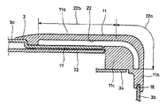
続いて、以上の如く構成されるシャッター機構10の詳細な動作について図8を参照して説明する。
図8Aはシャッター12によって操作部7が閉じられた状態であり、この状態から回動シャッター部材13に指を掛けてシャッター12を後方へ移動操作することにより、シャッター12はガイド溝22に沿って移動して図8Bに示すように操作部7を開いた状態となる。
またこの状態から回動シャッター部材13に指を掛けてシャッター12を前方へ移動操作することにより、シャッター12はガイド溝22に沿って移動して図8Aに示すように操作部7を閉じた状態となる。
【0036】
このシャッター12の移動操作において回動シャッター部材13は、後方のスライドピン25がガイド溝22の直線部22bに沿って移動すると共に、前方のスライドピン24がガイド溝22の曲線部22aに沿って移動し、このため回動シャッター部材13は後方のスライドピン25を支点として回転しながら移動するように動作される。
一方、直動シャッター部材14は回動シャッター部材13と連動して、スライド片26がガイド溝22の直線部22bに沿って移動することにより平面的に直線移動される。
【0037】
そして図8Aのようにシャッター12によって操作部7が閉じられた状態では、板ばね部材28のばね片部28aが前方の係合部30に係合し、この状態ではV字形のばね片部28aが係合部30を押圧して直動シャッター部材14を前方へ移動させようとしており、その力によって回動シャッター部材13が飾り枠11のストッパー面部35に押し付けられ、これによってシャッター12はその位置で固定状態に保持される。
【0038】
またこの板ばね部材28の作用により、操作部7を閉じる方向即ち前方へシャッター12を移動操作するときには、その動作の終端でシャッター12が引き込まれるように移動して回動シャッター部材13が飾り枠11のストッパー面部35に当たるように動作し、これによってシャッター12の移動操作において好適な引き込み感(トグル感)を得ることができる。
【0039】
一方、図8Bのようにシャッター12を後方に移動操作して操作部7を開いた状態では、板ばね部材28のばね片部28aが後方の係合部31に係合し、その状態でV字形のばね片部28aは係合部31の穴の前後端縁に当接して安定した状態で係合され、これによってシャッター12の後方への移動操作の終端においてクリックストップの使用感が得られてシャッター12はその位置で固定状態に保持される。
【0040】
以下の如く構成され動作される本例のシャッター機構10は次のような特徴を有している。
即ちこのシャッター機構10においてシャッター12の移動軌跡は、回転移動動作と平面的な直線移動動作を複合化(回転しながら平面移動も行なう)した動きであるため、シャッター12の実際の直線移動距離L1 に対し操作部材である回動シャッター部材13の回転移動動作での直線移動距離L2 は短く、このためシャッター12の見かけ上の移動距離が短く感じられる。
従ってシャッター12の移動操作においては、板ばね部材28によるクリックストップや引き込み感が感じられない距離が短く、回転移動動作における引き込み感が主体となるため、良好な操作感覚を得ることができるものである。
【0041】
またこのシャッター機構10は、その構成部品が筺体を含めて5点(筺体3、飾り枠11、回動シャッター部材13、直動シャッター部材14、板ばね部材28)と少なく、構成が簡単であり、組み立ても簡単であるため、低コストでの実施が可能である。
【0042】
さらにこのシャッター機構10では、飾り枠11に設けられるガイド溝22において直線部22bの一部を筺体3で形成した構造により、飾り枠11の厚みを薄く形成できて機構全体としての薄型化を可能としている。
【0043】
またこの構成により、外力に対するシャッター機構10の強度が充分に確保されるようになっている。
即ち、シャッター12が操作部7を開いた位置に移動された状態では、図8Bに示すように回動シャッター部材13が機器の表面から凸出する形となるため、この状態で機器を落下させたときにはこの回動シャッター部材13に衝撃が集中し易いが、この衝撃は飾り枠11と筺体3とで分散して受けられる状態となり、特に金属製の筺体3で衝撃が受けられることにより充分な強度を確保できるものである。
【0044】
またこのシャッター機構10は、機構全体が筺体3上の独立した空間内に収められたユニット構成となっており、動作部品であるシャッター12は機器の内部に対し筺体3で遮断されているため回路基板32やその他の内部部品と接触するおそれがなく、また組み立て時の逃がし距離を確保する必要もないので、機構の薄型化に有効である。
【0045】
またこのシャッター機構10では、シャッター12にクリックストップ及び引き込み感を与える部品として板ばね部材28を用い、これを直動シャッター部材14の裏面側に筺体3との間で取り付けた構造としたため、シャッター12の移動動作においてこの板ばね部材28が外れる等の不安定要素がなく、また板ばね部材28を直動シャッター部材14と筺体3との間の小空間に配した構造により、機構の薄型化に一段と有利となるものである。
【0046】
さらにこのシャッター機構10においてシャッター12の操作部材である回動シャッター部材13は、前後にスライドピン24,25を有し、これが左右両側に対称的に設けられてガイド溝22に係合されており、即ち回動シャッター部材13は4点でガイド溝22に支持された構造であるため、安定した移動動作が行なわれると共に、外力が加わったときの耐久性が充分に確保され、高強度のシャッター機構を実現している。
【0047】
以上、本発明の実施の形態例について説明したが、本発明はこの構成に限定されるものではない。
また本発明は例示したようなカセットプレーヤーに限ることなく、各種機器の操作部を開閉するメカニカルホールドシャッター機構に幅広く適用が可能なものである。
【0048】
【発明の効果】
以上の説明で明らかな如く本発明のシャッター機構は、回転移動動作と平面的な直線移動動作とが複合化した動きでシャッターが移動操作されることにより、見かけ上のシャッターの移動距離が短く感じられ、その結果良好なシャッターの操作感が得られて使い勝手が向上する。
【図面の簡単な説明】
【図1】本発明によるシャッター機構が適用された携帯型カセットプレーヤーの斜視図である。
【図2】同、裏返して見た斜視図である。
【図3】同、シャッター機構の部分を拡大した斜視図であり、Aはシャッターによって操作部が閉じられた状態、Bは開かれた状態である。
【図4】操作部におけるジョグスイッチの操作の説明図である。
【図5】筺体に対する飾り枠の取り付け構造を示す裏側から見た分解斜視図である。
【図6】ガイド溝の構造を示す縦断側面図である。
【図7】シャッターの構造を示す裏側から見た分解斜視図である。
【図8】本発明によるシャッター機構の縦断側面図で、Aはシャッターによって操作部が閉じられた状態、Bは開かれた状態である。
【図9】従来例のシャッター機構を示す平面図で、Aはシャッターによって操作部が閉じられた状態、Bは開かれた状態である。
【図10】同、シャッター機構を裏側から見た図で、Aはシャッターによって操作部が閉じられた状態、Bは開かれた状態である。
【符号の説明】
1‥‥カセットプレーヤー、2‥‥機器本体、3‥‥筺体、7‥‥操作部、8‥‥ジョグスイッチ、10‥‥シャッター機構、11‥‥飾り枠(体裁部品)、12‥‥シャッター、13‥‥回動シャッター部材、14‥‥直動シャッター部材、22‥‥ガイド溝、28‥‥板ばね部材、30,31‥‥係合部[0001]
BACKGROUND OF THE INVENTION
The present invention relates to a shutter mechanism that opens and closes an operation unit of a device, and a portable device including the shutter mechanism .
[0002]
[Prior art]
For example, in a portable audio device, in order to prevent an erroneous operation of the switch of the operation unit, a shutter that opens and closes the operation unit is provided, and the external unit is mechanically shut off by closing the operation unit with this shutter. Some use a mechanical hold shutter mechanism.
[0003]
An example of this type of conventional shutter mechanism shown in FIG. In the figure,
[0004]
The
[0005]
That Figure 9 A shows a state where the operation unit is closed by the
[0006]
Then by opening the
[0007]
Showing the structure of the operation mechanism of the
[0008]
FIG. 10 shows the
[0009]
A
[0010]
[Problems to be solved by the invention]
Such a conventional shutter mechanism has the following problems.
In other words, the conventional shutter mechanism has a structure in which the operation unit is opened and closed by simply moving the shutter linearly in a plane. Therefore, when the shutter is moved, the moving distance (stroke) is felt long and the operability is good. I can not say.
[0011]
The present invention has been made to solve such a problem, and an object of the present invention is to provide a shutter mechanism that can provide a good operational feeling.
[0012]
[Means for Solving the Problems]
In order to achieve the above object, the present invention provides:
In the shutter mechanism having a shutter that opens and closes the operation unit of the device,
The shutter is
A rotating shutter member formed in a substantially L-shape and operated to move while rotating along a guide groove provided on the device side;
A linear motion shutter member connected to the rotation shutter member, linearly moved in a plane along the guide groove in conjunction with the rotation shutter member, and having a flat plate shape ,
Composed of
A leaf spring member is attached to the direct-acting shutter member to engage with the engaging portion on the device side and hold the shutter in a fixed state at the position where the shutter is in the two positions of the closed position and the open position. The structure is obtained.
[0013]
In the shutter mechanism of the present invention configured as described above, the shutter is moved by a combined movement of rotational movement and planar linear movement, so that the apparent moving distance is felt short, and as a result, the shutter is moved. Good operation feeling can be obtained.
[0014]
DETAILED DESCRIPTION OF THE INVENTION
Hereinafter, embodiments of the present invention will be described in detail with reference to the drawings.
1 and 2 show a portable cassette player as an example of an audio device to which the shutter mechanism of the present invention is applied. FIG. 1 is a perspective view of the portable cassette player, and FIG.
[0015]
The cassette player 1 is a portable device with an auto reverse function that uses a compact tape cassette as a recording medium and can reproduce both A / B sides of a tape cassette driven by a rechargeable battery or a dry battery.
Reference numeral 6 denotes a headphone connection terminal, which is used by connecting a headphone device with a remote controller to the connection terminal 6.
[0016]
In the cassette player 1, an
[0017]
FIG. 3 is an enlarged view of the vicinity of the operation unit.
The
[0018]
In the
[0019]
In this
[0020]
The
The
On the other hand, the
[0021]
FIG. 3A shows a state in which the
[0022]
From this state, the
In order to make it easier to place a finger on the
[0023]
A more detailed structure of the
[0024]
FIG. 5 shows the attachment structure of the
Here, the
[0025]
The
[0026]
A plurality of
On the other hand, the
[0027]
Then, the
[0028]
FIG. 6 shows the structure of the
The guide grooves (cam grooves) 22 are formed symmetrically on both the left and right sides of the
The
[0029]
Here, the
[0030]
FIG. 7 shows the structure of the
As described above, the
The
On the other hand, the direct-acting
[0031]
Further, a connecting
The
[0032]
Further, in the
As is apparent from FIG. 7, the
[0033]
As shown in FIG. 8, the
Here, in this example, the front end edge of the stepped
[0034]
In FIG. 8,
[0035]
Next, the detailed operation of the
FIG. 8A shows a state in which the
Further, from this state, by placing a finger on the
[0036]
In the moving operation of the
On the other hand, the linearly moving
[0037]
8A, when the operating
[0038]
Further, when the
[0039]
On the other hand, in the state where the
[0040]
The
That is, in the
Accordingly, in the movement operation of the
[0041]
Further, the
[0042]
Furthermore, in this
[0043]
In addition, this configuration ensures sufficient strength of the
That is, when the
[0044]
The
[0045]
Further, in this
[0046]
Further, in this
[0047]
The embodiment of the present invention has been described above, but the present invention is not limited to this configuration.
Further, the present invention is not limited to the cassette player as illustrated, but can be widely applied to a mechanical hold shutter mechanism that opens and closes operation units of various devices.
[0048]
【The invention's effect】
As apparent from the above description, the shutter mechanism of the present invention feels that the apparent moving distance of the shutter is short because the shutter is moved by a combined movement of the rotational movement operation and the planar linear movement operation. As a result, a good shutter operation feeling can be obtained and the usability is improved.
[Brief description of the drawings]
FIG. 1 is a perspective view of a portable cassette player to which a shutter mechanism according to the present invention is applied.
FIG. 2 is a perspective view seen from the inside out.
FIG. 3 is an enlarged perspective view of the shutter mechanism, where A is a state where an operation unit is closed by a shutter and B is an open state.
FIG. 4 is an explanatory diagram of operation of a jog switch in an operation unit.
FIG. 5 is an exploded perspective view seen from the back side showing a structure for attaching a decorative frame to the housing.
FIG. 6 is a longitudinal side view showing a structure of a guide groove.
FIG. 7 is an exploded perspective view showing the structure of the shutter as seen from the back side.
8A and 8B are vertical side views of the shutter mechanism according to the present invention, in which A is a state in which an operation unit is closed by the shutter, and B is an open state.
FIGS. 9A and 9B are plan views showing a conventional shutter mechanism, in which A is a state where an operation unit is closed by a shutter, and B is an open state. FIGS.
FIG. 10 is a view of the shutter mechanism as seen from the back side, in which A is a state in which the operation unit is closed by the shutter, and B is an open state.
[Explanation of symbols]
DESCRIPTION OF SYMBOLS 1 ... cassette player, 2 ... device main body, 3 ... housing, 7 ... operation part, 8 ... jog switch, 10 ... shutter mechanism, 11 ... decoration frame (appearance parts), 12 ... shutter, DESCRIPTION OF
Claims (3)
上記シャッターは、
略L字型に形成され、且つ、機器側に設けられたガイド溝に沿って回転しながら移動するように操作される回動シャッター部材と、
この回動シャッター部材に連結され、この回動シャッター部材と連動して上記ガイド溝に沿って平面的に直線移動されると共に平板形状を有する直動シャッター部材と、により構成され、
上記直動シャッター部材には、上記シャッターが上記操作部を閉じた位置と開いた位置の二位置にある状態において機器側の係合部と係合し上記シャッターをその位置で固定状態に保持する板ばね部材が取り付けられてなるシャッター機構。A shutter mechanism having a shutter that opens and closes an operation unit of the device,
The shutter
A rotating shutter member formed in a substantially L-shape and operated to move while rotating along a guide groove provided on the device side;
A linear motion shutter member that is coupled to the rotation shutter member, is linearly moved in a plane along the guide groove in conjunction with the rotation shutter member, and has a flat plate shape , and
The linear shutter member engages with an engagement portion on the device side in a state where the shutter is in a position where the operation portion is closed and an open position, and the shutter is held in a fixed state at that position. A shutter mechanism to which a leaf spring member is attached.
上記操作部を開閉するシャッターとして、
略L字型に形成され、且つ、機器側に設けられたガイド溝に沿って回転しながら移動するように操作される回動シャッター部材と、
この回動シャッター部材に連結され、この回動シャッター部材と連動して上記ガイド溝に沿って平面的に直線移動されると共に平板形状を有する直動シャッター部材と、により構成され、
上記直動シャッター部材には、上記シャッターが上記操作部を閉じた位置と開いた位置の二位置にある状態において機器側の係合部と係合し上記シャッターをその位置で固定状態に保持する板ばね部材が取り付けられてなる携帯用機器。In a portable device provided with an operation unit,
As a shutter to open and close the operation unit,
A rotating shutter member formed in a substantially L-shape and operated to move while rotating along a guide groove provided on the device side;
A linear motion shutter member that is coupled to the rotation shutter member, is linearly moved in a plane along the guide groove in conjunction with the rotation shutter member, and has a flat plate shape , and
The linear shutter member engages with an engagement portion on the device side in a state where the shutter is in a position where the operation portion is closed and an open position, and the shutter is held in a fixed state at that position. A portable device to which a leaf spring member is attached.
Priority Applications (1)
| Application Number | Priority Date | Filing Date | Title |
|---|---|---|---|
| JP2000300333A JP4211212B2 (en) | 2000-09-29 | 2000-09-29 | Shutter mechanism and portable device |
Applications Claiming Priority (1)
| Application Number | Priority Date | Filing Date | Title |
|---|---|---|---|
| JP2000300333A JP4211212B2 (en) | 2000-09-29 | 2000-09-29 | Shutter mechanism and portable device |
Publications (3)
| Publication Number | Publication Date |
|---|---|
| JP2002109865A JP2002109865A (en) | 2002-04-12 |
| JP2002109865A5 JP2002109865A5 (en) | 2007-04-05 |
| JP4211212B2 true JP4211212B2 (en) | 2009-01-21 |
Family
ID=18782030
Family Applications (1)
| Application Number | Title | Priority Date | Filing Date |
|---|---|---|---|
| JP2000300333A Expired - Fee Related JP4211212B2 (en) | 2000-09-29 | 2000-09-29 | Shutter mechanism and portable device |
Country Status (1)
| Country | Link |
|---|---|
| JP (1) | JP4211212B2 (en) |
-
2000
- 2000-09-29 JP JP2000300333A patent/JP4211212B2/en not_active Expired - Fee Related
Also Published As
| Publication number | Publication date |
|---|---|
| JP2002109865A (en) | 2002-04-12 |
Similar Documents
| Publication | Publication Date | Title |
|---|---|---|
| JP2005210649A (en) | Sliding mechanism of mobile terminal | |
| JP3793290B2 (en) | Composite operation type electric parts | |
| JP2001023472A (en) | Switch and electronic apparatus using it | |
| JP4211212B2 (en) | Shutter mechanism and portable device | |
| JP2007157644A (en) | Switching device | |
| JP3744643B2 (en) | Multi-directional input device | |
| JP3613860B2 (en) | Radio control transmitter switch mechanism | |
| JPS5939823B2 (en) | Tape recorder mode switching device | |
| JP2002134960A (en) | Mounting structure of cosmetic component | |
| JP2000311551A (en) | Slide operation type switch | |
| JP2581481Y2 (en) | Push latch device | |
| JPH0731432Y2 (en) | Push-button structure with sliding open / close panel | |
| JPH10266663A (en) | Ignition switch | |
| JP4325285B2 (en) | Electronics | |
| JP3353343B2 (en) | Camera switch mechanism | |
| JP3702740B2 (en) | Lid device | |
| JPH1075070A (en) | Earphone housing device | |
| JP2836504B2 (en) | Magnet catcher for door | |
| JP3642074B2 (en) | Enclosure for electronic equipment | |
| JP2004319242A (en) | Switching arrangement | |
| JP3528276B2 (en) | Outer housing reinforcement | |
| KR940000478Y1 (en) | Portable cassette tape recorder | |
| JP3098853B2 (en) | Piano switch with contact switching display function | |
| JP2002050257A (en) | Sliding mechanism | |
| JPS5843070Y2 (en) | tape recorder tape recorder |
Legal Events
| Date | Code | Title | Description |
|---|---|---|---|
| A521 | Written amendment |
Free format text: JAPANESE INTERMEDIATE CODE: A523 Effective date: 20070215 |
|
| A621 | Written request for application examination |
Free format text: JAPANESE INTERMEDIATE CODE: A621 Effective date: 20070215 |
|
| A977 | Report on retrieval |
Free format text: JAPANESE INTERMEDIATE CODE: A971007 Effective date: 20080508 |
|
| A131 | Notification of reasons for refusal |
Free format text: JAPANESE INTERMEDIATE CODE: A131 Effective date: 20080715 |
|
| A521 | Written amendment |
Free format text: JAPANESE INTERMEDIATE CODE: A523 Effective date: 20080908 |
|
| TRDD | Decision of grant or rejection written | ||
| A01 | Written decision to grant a patent or to grant a registration (utility model) |
Free format text: JAPANESE INTERMEDIATE CODE: A01 Effective date: 20081007 |
|
| A01 | Written decision to grant a patent or to grant a registration (utility model) |
Free format text: JAPANESE INTERMEDIATE CODE: A01 |
|
| A61 | First payment of annual fees (during grant procedure) |
Free format text: JAPANESE INTERMEDIATE CODE: A61 Effective date: 20081020 |
|
| FPAY | Renewal fee payment (event date is renewal date of database) |
Free format text: PAYMENT UNTIL: 20111107 Year of fee payment: 3 |
|
| FPAY | Renewal fee payment (event date is renewal date of database) |
Free format text: PAYMENT UNTIL: 20111107 Year of fee payment: 3 |
|
| FPAY | Renewal fee payment (event date is renewal date of database) |
Free format text: PAYMENT UNTIL: 20111107 Year of fee payment: 3 |
|
| FPAY | Renewal fee payment (event date is renewal date of database) |
Free format text: PAYMENT UNTIL: 20121107 Year of fee payment: 4 |
|
| LAPS | Cancellation because of no payment of annual fees |