JP4210651B2 - Intervertebral implant having joint parts mounted on rolling elements - Google Patents
Intervertebral implant having joint parts mounted on rolling elements Download PDFInfo
- Publication number
- JP4210651B2 JP4210651B2 JP2004559543A JP2004559543A JP4210651B2 JP 4210651 B2 JP4210651 B2 JP 4210651B2 JP 2004559543 A JP2004559543 A JP 2004559543A JP 2004559543 A JP2004559543 A JP 2004559543A JP 4210651 B2 JP4210651 B2 JP 4210651B2
- Authority
- JP
- Japan
- Prior art keywords
- intervertebral implant
- joint
- axis
- intervertebral
- parts
- Prior art date
- Legal status (The legal status is an assumption and is not a legal conclusion. Google has not performed a legal analysis and makes no representation as to the accuracy of the status listed.)
- Expired - Fee Related
Links
Images


Classifications
-
- A—HUMAN NECESSITIES
- A61—MEDICAL OR VETERINARY SCIENCE; HYGIENE
- A61F—FILTERS IMPLANTABLE INTO BLOOD VESSELS; PROSTHESES; DEVICES PROVIDING PATENCY TO, OR PREVENTING COLLAPSING OF, TUBULAR STRUCTURES OF THE BODY, e.g. STENTS; ORTHOPAEDIC, NURSING OR CONTRACEPTIVE DEVICES; FOMENTATION; TREATMENT OR PROTECTION OF EYES OR EARS; BANDAGES, DRESSINGS OR ABSORBENT PADS; FIRST-AID KITS
- A61F2/00—Filters implantable into blood vessels; Prostheses, i.e. artificial substitutes or replacements for parts of the body; Appliances for connecting them with the body; Devices providing patency to, or preventing collapsing of, tubular structures of the body, e.g. stents
- A61F2/02—Prostheses implantable into the body
- A61F2/30—Joints
- A61F2/44—Joints for the spine, e.g. vertebrae, spinal discs
- A61F2/442—Intervertebral or spinal discs, e.g. resilient
- A61F2/4425—Intervertebral or spinal discs, e.g. resilient made of articulated components
-
- A—HUMAN NECESSITIES
- A61—MEDICAL OR VETERINARY SCIENCE; HYGIENE
- A61B—DIAGNOSIS; SURGERY; IDENTIFICATION
- A61B17/00—Surgical instruments, devices or methods, e.g. tourniquets
- A61B17/56—Surgical instruments or methods for treatment of bones or joints; Devices specially adapted therefor
- A61B17/58—Surgical instruments or methods for treatment of bones or joints; Devices specially adapted therefor for osteosynthesis, e.g. bone plates, screws, setting implements or the like
- A61B17/68—Internal fixation devices, including fasteners and spinal fixators, even if a part thereof projects from the skin
- A61B17/84—Fasteners therefor or fasteners being internal fixation devices
- A61B17/86—Pins or screws or threaded wires; nuts therefor
- A61B17/8625—Shanks, i.e. parts contacting bone tissue
- A61B17/863—Shanks, i.e. parts contacting bone tissue with thread interrupted or changing its form along shank, other than constant taper
-
- A—HUMAN NECESSITIES
- A61—MEDICAL OR VETERINARY SCIENCE; HYGIENE
- A61F—FILTERS IMPLANTABLE INTO BLOOD VESSELS; PROSTHESES; DEVICES PROVIDING PATENCY TO, OR PREVENTING COLLAPSING OF, TUBULAR STRUCTURES OF THE BODY, e.g. STENTS; ORTHOPAEDIC, NURSING OR CONTRACEPTIVE DEVICES; FOMENTATION; TREATMENT OR PROTECTION OF EYES OR EARS; BANDAGES, DRESSINGS OR ABSORBENT PADS; FIRST-AID KITS
- A61F2/00—Filters implantable into blood vessels; Prostheses, i.e. artificial substitutes or replacements for parts of the body; Appliances for connecting them with the body; Devices providing patency to, or preventing collapsing of, tubular structures of the body, e.g. stents
- A61F2/02—Prostheses implantable into the body
- A61F2/30—Joints
- A61F2/44—Joints for the spine, e.g. vertebrae, spinal discs
- A61F2/4455—Joints for the spine, e.g. vertebrae, spinal discs for the fusion of spinal bodies, e.g. intervertebral fusion of adjacent spinal bodies, e.g. fusion cages
-
- A—HUMAN NECESSITIES
- A61—MEDICAL OR VETERINARY SCIENCE; HYGIENE
- A61F—FILTERS IMPLANTABLE INTO BLOOD VESSELS; PROSTHESES; DEVICES PROVIDING PATENCY TO, OR PREVENTING COLLAPSING OF, TUBULAR STRUCTURES OF THE BODY, e.g. STENTS; ORTHOPAEDIC, NURSING OR CONTRACEPTIVE DEVICES; FOMENTATION; TREATMENT OR PROTECTION OF EYES OR EARS; BANDAGES, DRESSINGS OR ABSORBENT PADS; FIRST-AID KITS
- A61F2/00—Filters implantable into blood vessels; Prostheses, i.e. artificial substitutes or replacements for parts of the body; Appliances for connecting them with the body; Devices providing patency to, or preventing collapsing of, tubular structures of the body, e.g. stents
- A61F2/02—Prostheses implantable into the body
- A61F2/30—Joints
- A61F2002/30001—Additional features of subject-matter classified in A61F2/28, A61F2/30 and subgroups thereof
- A61F2002/30316—The prosthesis having different structural features at different locations within the same prosthesis; Connections between prosthetic parts; Special structural features of bone or joint prostheses not otherwise provided for
- A61F2002/30329—Connections or couplings between prosthetic parts, e.g. between modular parts; Connecting elements
- A61F2002/30331—Connections or couplings between prosthetic parts, e.g. between modular parts; Connecting elements made by longitudinally pushing a protrusion into a complementarily-shaped recess, e.g. held by friction fit
- A61F2002/30362—Connections or couplings between prosthetic parts, e.g. between modular parts; Connecting elements made by longitudinally pushing a protrusion into a complementarily-shaped recess, e.g. held by friction fit with possibility of relative movement between the protrusion and the recess
- A61F2002/30364—Rotation about the common longitudinal axis
- A61F2002/30365—Rotation about the common longitudinal axis with additional means for limiting said rotation
-
- A—HUMAN NECESSITIES
- A61—MEDICAL OR VETERINARY SCIENCE; HYGIENE
- A61F—FILTERS IMPLANTABLE INTO BLOOD VESSELS; PROSTHESES; DEVICES PROVIDING PATENCY TO, OR PREVENTING COLLAPSING OF, TUBULAR STRUCTURES OF THE BODY, e.g. STENTS; ORTHOPAEDIC, NURSING OR CONTRACEPTIVE DEVICES; FOMENTATION; TREATMENT OR PROTECTION OF EYES OR EARS; BANDAGES, DRESSINGS OR ABSORBENT PADS; FIRST-AID KITS
- A61F2/00—Filters implantable into blood vessels; Prostheses, i.e. artificial substitutes or replacements for parts of the body; Appliances for connecting them with the body; Devices providing patency to, or preventing collapsing of, tubular structures of the body, e.g. stents
- A61F2/02—Prostheses implantable into the body
- A61F2/30—Joints
- A61F2002/30001—Additional features of subject-matter classified in A61F2/28, A61F2/30 and subgroups thereof
- A61F2002/30316—The prosthesis having different structural features at different locations within the same prosthesis; Connections between prosthetic parts; Special structural features of bone or joint prostheses not otherwise provided for
- A61F2002/30329—Connections or couplings between prosthetic parts, e.g. between modular parts; Connecting elements
- A61F2002/30383—Connections or couplings between prosthetic parts, e.g. between modular parts; Connecting elements made by laterally inserting a protrusion, e.g. a rib into a complementarily-shaped groove
- A61F2002/30387—Dovetail connection
-
- A—HUMAN NECESSITIES
- A61—MEDICAL OR VETERINARY SCIENCE; HYGIENE
- A61F—FILTERS IMPLANTABLE INTO BLOOD VESSELS; PROSTHESES; DEVICES PROVIDING PATENCY TO, OR PREVENTING COLLAPSING OF, TUBULAR STRUCTURES OF THE BODY, e.g. STENTS; ORTHOPAEDIC, NURSING OR CONTRACEPTIVE DEVICES; FOMENTATION; TREATMENT OR PROTECTION OF EYES OR EARS; BANDAGES, DRESSINGS OR ABSORBENT PADS; FIRST-AID KITS
- A61F2/00—Filters implantable into blood vessels; Prostheses, i.e. artificial substitutes or replacements for parts of the body; Appliances for connecting them with the body; Devices providing patency to, or preventing collapsing of, tubular structures of the body, e.g. stents
- A61F2/02—Prostheses implantable into the body
- A61F2/30—Joints
- A61F2002/30001—Additional features of subject-matter classified in A61F2/28, A61F2/30 and subgroups thereof
- A61F2002/30316—The prosthesis having different structural features at different locations within the same prosthesis; Connections between prosthetic parts; Special structural features of bone or joint prostheses not otherwise provided for
- A61F2002/30329—Connections or couplings between prosthetic parts, e.g. between modular parts; Connecting elements
- A61F2002/30383—Connections or couplings between prosthetic parts, e.g. between modular parts; Connecting elements made by laterally inserting a protrusion, e.g. a rib into a complementarily-shaped groove
- A61F2002/3039—Connections or couplings between prosthetic parts, e.g. between modular parts; Connecting elements made by laterally inserting a protrusion, e.g. a rib into a complementarily-shaped groove with possibility of relative movement of the rib within the groove
- A61F2002/30392—Rotation
- A61F2002/30393—Rotation with additional means for limiting said rotation
-
- A—HUMAN NECESSITIES
- A61—MEDICAL OR VETERINARY SCIENCE; HYGIENE
- A61F—FILTERS IMPLANTABLE INTO BLOOD VESSELS; PROSTHESES; DEVICES PROVIDING PATENCY TO, OR PREVENTING COLLAPSING OF, TUBULAR STRUCTURES OF THE BODY, e.g. STENTS; ORTHOPAEDIC, NURSING OR CONTRACEPTIVE DEVICES; FOMENTATION; TREATMENT OR PROTECTION OF EYES OR EARS; BANDAGES, DRESSINGS OR ABSORBENT PADS; FIRST-AID KITS
- A61F2/00—Filters implantable into blood vessels; Prostheses, i.e. artificial substitutes or replacements for parts of the body; Appliances for connecting them with the body; Devices providing patency to, or preventing collapsing of, tubular structures of the body, e.g. stents
- A61F2/02—Prostheses implantable into the body
- A61F2/30—Joints
- A61F2002/30001—Additional features of subject-matter classified in A61F2/28, A61F2/30 and subgroups thereof
- A61F2002/30316—The prosthesis having different structural features at different locations within the same prosthesis; Connections between prosthetic parts; Special structural features of bone or joint prostheses not otherwise provided for
- A61F2002/30329—Connections or couplings between prosthetic parts, e.g. between modular parts; Connecting elements
- A61F2002/30476—Connections or couplings between prosthetic parts, e.g. between modular parts; Connecting elements locked by an additional locking mechanism
- A61F2002/30492—Connections or couplings between prosthetic parts, e.g. between modular parts; Connecting elements locked by an additional locking mechanism using a locking pin
-
- A—HUMAN NECESSITIES
- A61—MEDICAL OR VETERINARY SCIENCE; HYGIENE
- A61F—FILTERS IMPLANTABLE INTO BLOOD VESSELS; PROSTHESES; DEVICES PROVIDING PATENCY TO, OR PREVENTING COLLAPSING OF, TUBULAR STRUCTURES OF THE BODY, e.g. STENTS; ORTHOPAEDIC, NURSING OR CONTRACEPTIVE DEVICES; FOMENTATION; TREATMENT OR PROTECTION OF EYES OR EARS; BANDAGES, DRESSINGS OR ABSORBENT PADS; FIRST-AID KITS
- A61F2/00—Filters implantable into blood vessels; Prostheses, i.e. artificial substitutes or replacements for parts of the body; Appliances for connecting them with the body; Devices providing patency to, or preventing collapsing of, tubular structures of the body, e.g. stents
- A61F2/02—Prostheses implantable into the body
- A61F2/30—Joints
- A61F2002/30001—Additional features of subject-matter classified in A61F2/28, A61F2/30 and subgroups thereof
- A61F2002/30316—The prosthesis having different structural features at different locations within the same prosthesis; Connections between prosthetic parts; Special structural features of bone or joint prostheses not otherwise provided for
- A61F2002/30329—Connections or couplings between prosthetic parts, e.g. between modular parts; Connecting elements
- A61F2002/30476—Connections or couplings between prosthetic parts, e.g. between modular parts; Connecting elements locked by an additional locking mechanism
- A61F2002/30507—Connections or couplings between prosthetic parts, e.g. between modular parts; Connecting elements locked by an additional locking mechanism using a threaded locking member, e.g. a locking screw or a set screw
-
- A—HUMAN NECESSITIES
- A61—MEDICAL OR VETERINARY SCIENCE; HYGIENE
- A61F—FILTERS IMPLANTABLE INTO BLOOD VESSELS; PROSTHESES; DEVICES PROVIDING PATENCY TO, OR PREVENTING COLLAPSING OF, TUBULAR STRUCTURES OF THE BODY, e.g. STENTS; ORTHOPAEDIC, NURSING OR CONTRACEPTIVE DEVICES; FOMENTATION; TREATMENT OR PROTECTION OF EYES OR EARS; BANDAGES, DRESSINGS OR ABSORBENT PADS; FIRST-AID KITS
- A61F2/00—Filters implantable into blood vessels; Prostheses, i.e. artificial substitutes or replacements for parts of the body; Appliances for connecting them with the body; Devices providing patency to, or preventing collapsing of, tubular structures of the body, e.g. stents
- A61F2/02—Prostheses implantable into the body
- A61F2/30—Joints
- A61F2002/30001—Additional features of subject-matter classified in A61F2/28, A61F2/30 and subgroups thereof
- A61F2002/30316—The prosthesis having different structural features at different locations within the same prosthesis; Connections between prosthetic parts; Special structural features of bone or joint prostheses not otherwise provided for
- A61F2002/30329—Connections or couplings between prosthetic parts, e.g. between modular parts; Connecting elements
- A61F2002/30476—Connections or couplings between prosthetic parts, e.g. between modular parts; Connecting elements locked by an additional locking mechanism
- A61F2002/30515—Connections or couplings between prosthetic parts, e.g. between modular parts; Connecting elements locked by an additional locking mechanism using a locking wedge or block
-
- A—HUMAN NECESSITIES
- A61—MEDICAL OR VETERINARY SCIENCE; HYGIENE
- A61F—FILTERS IMPLANTABLE INTO BLOOD VESSELS; PROSTHESES; DEVICES PROVIDING PATENCY TO, OR PREVENTING COLLAPSING OF, TUBULAR STRUCTURES OF THE BODY, e.g. STENTS; ORTHOPAEDIC, NURSING OR CONTRACEPTIVE DEVICES; FOMENTATION; TREATMENT OR PROTECTION OF EYES OR EARS; BANDAGES, DRESSINGS OR ABSORBENT PADS; FIRST-AID KITS
- A61F2/00—Filters implantable into blood vessels; Prostheses, i.e. artificial substitutes or replacements for parts of the body; Appliances for connecting them with the body; Devices providing patency to, or preventing collapsing of, tubular structures of the body, e.g. stents
- A61F2/02—Prostheses implantable into the body
- A61F2/30—Joints
- A61F2002/30001—Additional features of subject-matter classified in A61F2/28, A61F2/30 and subgroups thereof
- A61F2002/30316—The prosthesis having different structural features at different locations within the same prosthesis; Connections between prosthetic parts; Special structural features of bone or joint prostheses not otherwise provided for
- A61F2002/30329—Connections or couplings between prosthetic parts, e.g. between modular parts; Connecting elements
- A61F2002/30476—Connections or couplings between prosthetic parts, e.g. between modular parts; Connecting elements locked by an additional locking mechanism
- A61F2002/30517—Connections or couplings between prosthetic parts, e.g. between modular parts; Connecting elements locked by an additional locking mechanism using a locking plate
-
- A—HUMAN NECESSITIES
- A61—MEDICAL OR VETERINARY SCIENCE; HYGIENE
- A61F—FILTERS IMPLANTABLE INTO BLOOD VESSELS; PROSTHESES; DEVICES PROVIDING PATENCY TO, OR PREVENTING COLLAPSING OF, TUBULAR STRUCTURES OF THE BODY, e.g. STENTS; ORTHOPAEDIC, NURSING OR CONTRACEPTIVE DEVICES; FOMENTATION; TREATMENT OR PROTECTION OF EYES OR EARS; BANDAGES, DRESSINGS OR ABSORBENT PADS; FIRST-AID KITS
- A61F2/00—Filters implantable into blood vessels; Prostheses, i.e. artificial substitutes or replacements for parts of the body; Appliances for connecting them with the body; Devices providing patency to, or preventing collapsing of, tubular structures of the body, e.g. stents
- A61F2/02—Prostheses implantable into the body
- A61F2/30—Joints
- A61F2002/30001—Additional features of subject-matter classified in A61F2/28, A61F2/30 and subgroups thereof
- A61F2002/30316—The prosthesis having different structural features at different locations within the same prosthesis; Connections between prosthetic parts; Special structural features of bone or joint prostheses not otherwise provided for
- A61F2002/30329—Connections or couplings between prosthetic parts, e.g. between modular parts; Connecting elements
- A61F2002/30518—Connections or couplings between prosthetic parts, e.g. between modular parts; Connecting elements with possibility of relative movement between the prosthetic parts
- A61F2002/30528—Means for limiting said movement
-
- A—HUMAN NECESSITIES
- A61—MEDICAL OR VETERINARY SCIENCE; HYGIENE
- A61F—FILTERS IMPLANTABLE INTO BLOOD VESSELS; PROSTHESES; DEVICES PROVIDING PATENCY TO, OR PREVENTING COLLAPSING OF, TUBULAR STRUCTURES OF THE BODY, e.g. STENTS; ORTHOPAEDIC, NURSING OR CONTRACEPTIVE DEVICES; FOMENTATION; TREATMENT OR PROTECTION OF EYES OR EARS; BANDAGES, DRESSINGS OR ABSORBENT PADS; FIRST-AID KITS
- A61F2/00—Filters implantable into blood vessels; Prostheses, i.e. artificial substitutes or replacements for parts of the body; Appliances for connecting them with the body; Devices providing patency to, or preventing collapsing of, tubular structures of the body, e.g. stents
- A61F2/02—Prostheses implantable into the body
- A61F2/30—Joints
- A61F2002/30001—Additional features of subject-matter classified in A61F2/28, A61F2/30 and subgroups thereof
- A61F2002/30316—The prosthesis having different structural features at different locations within the same prosthesis; Connections between prosthetic parts; Special structural features of bone or joint prostheses not otherwise provided for
- A61F2002/30535—Special structural features of bone or joint prostheses not otherwise provided for
- A61F2002/30604—Special structural features of bone or joint prostheses not otherwise provided for modular
-
- A—HUMAN NECESSITIES
- A61—MEDICAL OR VETERINARY SCIENCE; HYGIENE
- A61F—FILTERS IMPLANTABLE INTO BLOOD VESSELS; PROSTHESES; DEVICES PROVIDING PATENCY TO, OR PREVENTING COLLAPSING OF, TUBULAR STRUCTURES OF THE BODY, e.g. STENTS; ORTHOPAEDIC, NURSING OR CONTRACEPTIVE DEVICES; FOMENTATION; TREATMENT OR PROTECTION OF EYES OR EARS; BANDAGES, DRESSINGS OR ABSORBENT PADS; FIRST-AID KITS
- A61F2/00—Filters implantable into blood vessels; Prostheses, i.e. artificial substitutes or replacements for parts of the body; Appliances for connecting them with the body; Devices providing patency to, or preventing collapsing of, tubular structures of the body, e.g. stents
- A61F2/02—Prostheses implantable into the body
- A61F2/30—Joints
- A61F2002/30001—Additional features of subject-matter classified in A61F2/28, A61F2/30 and subgroups thereof
- A61F2002/30621—Features concerning the anatomical functioning or articulation of the prosthetic joint
- A61F2002/30624—Hinged joint, e.g. with transverse axle restricting the movement
- A61F2002/30632—Hinged joint, e.g. with transverse axle restricting the movement with rotation-limiting stops, e.g. projections or recesses
-
- A—HUMAN NECESSITIES
- A61—MEDICAL OR VETERINARY SCIENCE; HYGIENE
- A61F—FILTERS IMPLANTABLE INTO BLOOD VESSELS; PROSTHESES; DEVICES PROVIDING PATENCY TO, OR PREVENTING COLLAPSING OF, TUBULAR STRUCTURES OF THE BODY, e.g. STENTS; ORTHOPAEDIC, NURSING OR CONTRACEPTIVE DEVICES; FOMENTATION; TREATMENT OR PROTECTION OF EYES OR EARS; BANDAGES, DRESSINGS OR ABSORBENT PADS; FIRST-AID KITS
- A61F2/00—Filters implantable into blood vessels; Prostheses, i.e. artificial substitutes or replacements for parts of the body; Appliances for connecting them with the body; Devices providing patency to, or preventing collapsing of, tubular structures of the body, e.g. stents
- A61F2/02—Prostheses implantable into the body
- A61F2/30—Joints
- A61F2002/30001—Additional features of subject-matter classified in A61F2/28, A61F2/30 and subgroups thereof
- A61F2002/30621—Features concerning the anatomical functioning or articulation of the prosthetic joint
- A61F2002/30624—Hinged joint, e.g. with transverse axle restricting the movement
- A61F2002/30634—Hinged joint, e.g. with transverse axle restricting the movement biaxial
-
- A—HUMAN NECESSITIES
- A61—MEDICAL OR VETERINARY SCIENCE; HYGIENE
- A61F—FILTERS IMPLANTABLE INTO BLOOD VESSELS; PROSTHESES; DEVICES PROVIDING PATENCY TO, OR PREVENTING COLLAPSING OF, TUBULAR STRUCTURES OF THE BODY, e.g. STENTS; ORTHOPAEDIC, NURSING OR CONTRACEPTIVE DEVICES; FOMENTATION; TREATMENT OR PROTECTION OF EYES OR EARS; BANDAGES, DRESSINGS OR ABSORBENT PADS; FIRST-AID KITS
- A61F2/00—Filters implantable into blood vessels; Prostheses, i.e. artificial substitutes or replacements for parts of the body; Appliances for connecting them with the body; Devices providing patency to, or preventing collapsing of, tubular structures of the body, e.g. stents
- A61F2/02—Prostheses implantable into the body
- A61F2/30—Joints
- A61F2002/30001—Additional features of subject-matter classified in A61F2/28, A61F2/30 and subgroups thereof
- A61F2002/30621—Features concerning the anatomical functioning or articulation of the prosthetic joint
- A61F2002/30639—Features concerning the anatomical functioning or articulation of the prosthetic joint having rolling elements between both articulating surfaces
-
- A—HUMAN NECESSITIES
- A61—MEDICAL OR VETERINARY SCIENCE; HYGIENE
- A61F—FILTERS IMPLANTABLE INTO BLOOD VESSELS; PROSTHESES; DEVICES PROVIDING PATENCY TO, OR PREVENTING COLLAPSING OF, TUBULAR STRUCTURES OF THE BODY, e.g. STENTS; ORTHOPAEDIC, NURSING OR CONTRACEPTIVE DEVICES; FOMENTATION; TREATMENT OR PROTECTION OF EYES OR EARS; BANDAGES, DRESSINGS OR ABSORBENT PADS; FIRST-AID KITS
- A61F2/00—Filters implantable into blood vessels; Prostheses, i.e. artificial substitutes or replacements for parts of the body; Appliances for connecting them with the body; Devices providing patency to, or preventing collapsing of, tubular structures of the body, e.g. stents
- A61F2/02—Prostheses implantable into the body
- A61F2/30—Joints
- A61F2/30767—Special external or bone-contacting surface, e.g. coating for improving bone ingrowth
- A61F2/30771—Special external or bone-contacting surface, e.g. coating for improving bone ingrowth applied in original prostheses, e.g. holes or grooves
- A61F2002/30772—Apertures or holes, e.g. of circular cross section
- A61F2002/30774—Apertures or holes, e.g. of circular cross section internally-threaded
-
- A—HUMAN NECESSITIES
- A61—MEDICAL OR VETERINARY SCIENCE; HYGIENE
- A61F—FILTERS IMPLANTABLE INTO BLOOD VESSELS; PROSTHESES; DEVICES PROVIDING PATENCY TO, OR PREVENTING COLLAPSING OF, TUBULAR STRUCTURES OF THE BODY, e.g. STENTS; ORTHOPAEDIC, NURSING OR CONTRACEPTIVE DEVICES; FOMENTATION; TREATMENT OR PROTECTION OF EYES OR EARS; BANDAGES, DRESSINGS OR ABSORBENT PADS; FIRST-AID KITS
- A61F2/00—Filters implantable into blood vessels; Prostheses, i.e. artificial substitutes or replacements for parts of the body; Appliances for connecting them with the body; Devices providing patency to, or preventing collapsing of, tubular structures of the body, e.g. stents
- A61F2/02—Prostheses implantable into the body
- A61F2/30—Joints
- A61F2/30767—Special external or bone-contacting surface, e.g. coating for improving bone ingrowth
- A61F2/30771—Special external or bone-contacting surface, e.g. coating for improving bone ingrowth applied in original prostheses, e.g. holes or grooves
- A61F2002/30772—Apertures or holes, e.g. of circular cross section
- A61F2002/30784—Plurality of holes
- A61F2002/30785—Plurality of holes parallel
-
- A—HUMAN NECESSITIES
- A61—MEDICAL OR VETERINARY SCIENCE; HYGIENE
- A61F—FILTERS IMPLANTABLE INTO BLOOD VESSELS; PROSTHESES; DEVICES PROVIDING PATENCY TO, OR PREVENTING COLLAPSING OF, TUBULAR STRUCTURES OF THE BODY, e.g. STENTS; ORTHOPAEDIC, NURSING OR CONTRACEPTIVE DEVICES; FOMENTATION; TREATMENT OR PROTECTION OF EYES OR EARS; BANDAGES, DRESSINGS OR ABSORBENT PADS; FIRST-AID KITS
- A61F2/00—Filters implantable into blood vessels; Prostheses, i.e. artificial substitutes or replacements for parts of the body; Appliances for connecting them with the body; Devices providing patency to, or preventing collapsing of, tubular structures of the body, e.g. stents
- A61F2/02—Prostheses implantable into the body
- A61F2/30—Joints
- A61F2/30767—Special external or bone-contacting surface, e.g. coating for improving bone ingrowth
- A61F2/30771—Special external or bone-contacting surface, e.g. coating for improving bone ingrowth applied in original prostheses, e.g. holes or grooves
- A61F2002/30772—Apertures or holes, e.g. of circular cross section
- A61F2002/30784—Plurality of holes
- A61F2002/30787—Plurality of holes inclined obliquely with respect to each other
-
- A—HUMAN NECESSITIES
- A61—MEDICAL OR VETERINARY SCIENCE; HYGIENE
- A61F—FILTERS IMPLANTABLE INTO BLOOD VESSELS; PROSTHESES; DEVICES PROVIDING PATENCY TO, OR PREVENTING COLLAPSING OF, TUBULAR STRUCTURES OF THE BODY, e.g. STENTS; ORTHOPAEDIC, NURSING OR CONTRACEPTIVE DEVICES; FOMENTATION; TREATMENT OR PROTECTION OF EYES OR EARS; BANDAGES, DRESSINGS OR ABSORBENT PADS; FIRST-AID KITS
- A61F2/00—Filters implantable into blood vessels; Prostheses, i.e. artificial substitutes or replacements for parts of the body; Appliances for connecting them with the body; Devices providing patency to, or preventing collapsing of, tubular structures of the body, e.g. stents
- A61F2/02—Prostheses implantable into the body
- A61F2/30—Joints
- A61F2/30767—Special external or bone-contacting surface, e.g. coating for improving bone ingrowth
- A61F2/30771—Special external or bone-contacting surface, e.g. coating for improving bone ingrowth applied in original prostheses, e.g. holes or grooves
- A61F2002/30772—Apertures or holes, e.g. of circular cross section
- A61F2002/3079—Stepped or enlarged apertures, e.g. having discrete diameter changes
-
- A—HUMAN NECESSITIES
- A61—MEDICAL OR VETERINARY SCIENCE; HYGIENE
- A61F—FILTERS IMPLANTABLE INTO BLOOD VESSELS; PROSTHESES; DEVICES PROVIDING PATENCY TO, OR PREVENTING COLLAPSING OF, TUBULAR STRUCTURES OF THE BODY, e.g. STENTS; ORTHOPAEDIC, NURSING OR CONTRACEPTIVE DEVICES; FOMENTATION; TREATMENT OR PROTECTION OF EYES OR EARS; BANDAGES, DRESSINGS OR ABSORBENT PADS; FIRST-AID KITS
- A61F2/00—Filters implantable into blood vessels; Prostheses, i.e. artificial substitutes or replacements for parts of the body; Appliances for connecting them with the body; Devices providing patency to, or preventing collapsing of, tubular structures of the body, e.g. stents
- A61F2/02—Prostheses implantable into the body
- A61F2/30—Joints
- A61F2/30767—Special external or bone-contacting surface, e.g. coating for improving bone ingrowth
- A61F2/30771—Special external or bone-contacting surface, e.g. coating for improving bone ingrowth applied in original prostheses, e.g. holes or grooves
- A61F2002/30841—Sharp anchoring protrusions for impaction into the bone, e.g. sharp pins, spikes
- A61F2002/30843—Pyramidally-shaped
-
- A—HUMAN NECESSITIES
- A61—MEDICAL OR VETERINARY SCIENCE; HYGIENE
- A61F—FILTERS IMPLANTABLE INTO BLOOD VESSELS; PROSTHESES; DEVICES PROVIDING PATENCY TO, OR PREVENTING COLLAPSING OF, TUBULAR STRUCTURES OF THE BODY, e.g. STENTS; ORTHOPAEDIC, NURSING OR CONTRACEPTIVE DEVICES; FOMENTATION; TREATMENT OR PROTECTION OF EYES OR EARS; BANDAGES, DRESSINGS OR ABSORBENT PADS; FIRST-AID KITS
- A61F2/00—Filters implantable into blood vessels; Prostheses, i.e. artificial substitutes or replacements for parts of the body; Appliances for connecting them with the body; Devices providing patency to, or preventing collapsing of, tubular structures of the body, e.g. stents
- A61F2/02—Prostheses implantable into the body
- A61F2/30—Joints
- A61F2/44—Joints for the spine, e.g. vertebrae, spinal discs
- A61F2/442—Intervertebral or spinal discs, e.g. resilient
- A61F2/4425—Intervertebral or spinal discs, e.g. resilient made of articulated components
- A61F2002/443—Intervertebral or spinal discs, e.g. resilient made of articulated components having two transversal endplates and at least one intermediate component
-
- A—HUMAN NECESSITIES
- A61—MEDICAL OR VETERINARY SCIENCE; HYGIENE
- A61F—FILTERS IMPLANTABLE INTO BLOOD VESSELS; PROSTHESES; DEVICES PROVIDING PATENCY TO, OR PREVENTING COLLAPSING OF, TUBULAR STRUCTURES OF THE BODY, e.g. STENTS; ORTHOPAEDIC, NURSING OR CONTRACEPTIVE DEVICES; FOMENTATION; TREATMENT OR PROTECTION OF EYES OR EARS; BANDAGES, DRESSINGS OR ABSORBENT PADS; FIRST-AID KITS
- A61F2/00—Filters implantable into blood vessels; Prostheses, i.e. artificial substitutes or replacements for parts of the body; Appliances for connecting them with the body; Devices providing patency to, or preventing collapsing of, tubular structures of the body, e.g. stents
- A61F2/02—Prostheses implantable into the body
- A61F2/30—Joints
- A61F2/46—Special tools or methods for implanting or extracting artificial joints, accessories, bone grafts or substitutes, or particular adaptations therefor
- A61F2002/4635—Special tools or methods for implanting or extracting artificial joints, accessories, bone grafts or substitutes, or particular adaptations therefor using minimally invasive surgery
-
- A—HUMAN NECESSITIES
- A61—MEDICAL OR VETERINARY SCIENCE; HYGIENE
- A61F—FILTERS IMPLANTABLE INTO BLOOD VESSELS; PROSTHESES; DEVICES PROVIDING PATENCY TO, OR PREVENTING COLLAPSING OF, TUBULAR STRUCTURES OF THE BODY, e.g. STENTS; ORTHOPAEDIC, NURSING OR CONTRACEPTIVE DEVICES; FOMENTATION; TREATMENT OR PROTECTION OF EYES OR EARS; BANDAGES, DRESSINGS OR ABSORBENT PADS; FIRST-AID KITS
- A61F2220/00—Fixations or connections for prostheses classified in groups A61F2/00 - A61F2/26 or A61F2/82 or A61F9/00 or A61F11/00 or subgroups thereof
- A61F2220/0025—Connections or couplings between prosthetic parts, e.g. between modular parts; Connecting elements
- A61F2220/0033—Connections or couplings between prosthetic parts, e.g. between modular parts; Connecting elements made by longitudinally pushing a protrusion into a complementary-shaped recess, e.g. held by friction fit
Landscapes
- Health & Medical Sciences (AREA)
- Engineering & Computer Science (AREA)
- Biomedical Technology (AREA)
- Orthopedic Medicine & Surgery (AREA)
- Neurology (AREA)
- Life Sciences & Earth Sciences (AREA)
- Animal Behavior & Ethology (AREA)
- Veterinary Medicine (AREA)
- Public Health (AREA)
- Heart & Thoracic Surgery (AREA)
- General Health & Medical Sciences (AREA)
- Cardiology (AREA)
- Vascular Medicine (AREA)
- Transplantation (AREA)
- Oral & Maxillofacial Surgery (AREA)
- Surgery (AREA)
- Nuclear Medicine, Radiotherapy & Molecular Imaging (AREA)
- Medical Informatics (AREA)
- Molecular Biology (AREA)
- Prostheses (AREA)
Description
本発明は、特許請求の範囲第1項の前文による椎間インプラント、および障害のある自然の椎間板を特許請求の範囲第20項による椎間インプラントによって置換するための方法に関する。
The invention relates to an intervertebral implant according to the preamble of
障害のある自然の椎間板、または障害のある椎間板髄核の除去後、インプラントまたはプロテーゼが2つの隣接した椎体の椎間腔へ導入される。この場合、再びできるだけ自然の状態をもたらすこと、すなわち、特に本来の椎間板高さとともに隣接した椎体間の本来の距離を再現する目標が生じる。さらに、隣接した椎体の動きは互いに対してできるだけ障害なしにその自然な方式で達成されなければならない。このために、前方/後方傾斜、すなわち椎体の屈曲および伸展のほか、自然の限界内での椎体の外側の曲げに際しての可動性の保持が重要である。脊柱に沿った自然の靱帯および筋は実質的に無傷にされるため、これらが機械的椎間板代用物の動きを安定化する。 After removal of the damaged natural disc or the nucleus pulposus of the damaged disc, an implant or prosthesis is introduced into the intervertebral space of two adjacent vertebral bodies. In this case, the goal is to bring the natural state again as much as possible, ie to reproduce the original distance between adjacent vertebral bodies as well as the original intervertebral disc height. Furthermore, movements of adjacent vertebral bodies must be achieved in their natural manner with as little disturbance as possible relative to each other. For this reason, it is important to maintain mobility during anterior / posterior tilt, ie bending and extension of the vertebral body, as well as bending outside the vertebral body within natural limits. Since the natural ligaments and muscles along the spinal column are substantially rendered intact, they stabilize the movement of the mechanical disc substitute.
この種の椎間板エンドプロテーゼが、ビュトナーによるドイツ特許(DE−A)第3529761号により周知である。この周知の椎間板エンドプロテーゼは、互いに対してくぼんだ滑面およびそれぞれ底板、隣接した椎体のそれぞれ蓋板へ取付けるための外側表面を有する実質的に2つの対称の閉鎖プレートと、閉鎖プレーとにおけるくぼんだ滑面に対して補完的に構成されたくぼんだ滑面を有する閉鎖プレート間に位置したスペーサーとから成る。これらの滑面は、ある実施例においては、シリンダジャケット面に部分面として構成されており、ここで両方の閉鎖プレートに配置された滑面がスペーサーにおいて隣接した滑面のそれぞれ1つに対して補完的に構成されており、それぞれ2つの補完的な滑面が回転軸の周りを回転可能な関節部品の互いに移動可能な関節面を形成する。関節部品はそれぞれ回転軸を有する上下の関節部品を含んで成る。両方の回転軸は、互いに90°で配置されている。この周知の椎間板エンドプロテーゼの不利点は、
a)自然な椎間板においては互いに独立している特に前後および外側屈曲に際して自然の椎間板によって伝達可能な層をなして重なった旋回移動が、ターニングセンタのみでの椎間板エンドプロテーゼの構成によって考慮されないこと、
b)特に前後方向の並進運動に際して、剪断運動によって、脊椎関節(ファセット関節)が負荷を受け、それによって患者の疼痛の原因となりうること、
c)2つの互いに摺動可能な関節面における不利な摩擦力が生じること。さらに、それぞれの面に消耗、すなわち、とりわけ関節部品の運動のため摩滅および抵抗が生じる。さらに、「スティックスリップ」作用が生じること、
d)機械的な椎間板代用物が関係した運動部分のさらなる変性をほとんど止めることがないこと。本来の運動関係の再現は疼痛を実質的に削減し、患者は生活の質が改善する。しかし、疼痛の新しい出現に際しては、管理の修正に取り組む必要がある。この場合、通常は、従来の構造による椎間板プロテーゼが完全に除去され、運動部分は強化される。この操作は患者にとって非常に負担となること、および
e)隣接した椎体に対する接触面の形態が通常、考慮されないこと。従来の構造の椎間板代用インプラントは平らな(フラットな)接触面を有し、これはしばしば竜骨状の隆起で補充されていることである。
a) the pivoting movements that overlap in layers that can be transmitted by the natural intervertebral discs that are independent of each other in the natural intervertebral disc, especially during anteroposterior and lateral flexion, are not taken into account by the configuration of the intervertebral disc endoprosthesis at the turning center alone;
b) The spinal joint (facet joint) is loaded by shearing movements, especially during longitudinal translation, which can cause pain in the patient;
c) An unfavorable frictional force is generated at the two mutually slidable joint surfaces. In addition, wear and resistance occurs on each surface due to wear, i.e., inter alia, movement of joint parts. In addition, a “stick-slip” effect occurs,
d) Almost no further degeneration of the moving part associated with the mechanical disc substitute. Reproduction of the original motor relationship substantially reduces pain and improves the quality of life for patients. However, with the new emergence of pain, management corrections need to be addressed. In this case, usually the intervertebral disc prosthesis according to the conventional structure is completely removed and the movement part is strengthened. This operation is very burdensome for the patient and e) the form of the contact surface to the adjacent vertebral body is usually not considered. Conventionally structured disc replacement implants have a flat (flat) contact surface, which is often filled with keel-like ridges.
この点で本発明は改善を提供することになる。本発明の課題は、関節を含んで成り、その関節軸が最小限の摩擦の軸受を有する椎間インプラントを提供することである。
本発明は、請求項1の特徴を有する椎間インプラントにより、かつ請求項2のステップを含んで成る椎間板インプラントによって障害のある自然の椎間板を置換する方法により上記の課題を解決する。
In this respect, the present invention provides an improvement. The object of the present invention is to provide an intervertebral implant comprising a joint, the joint axis of which has a bearing with minimal friction.
The present invention solves the above problem by a method of replacing a damaged natural disc by an intervertebral implant having the features of
本発明によって達成される利点は、実質的に、本発明による椎間インプラントにより、
−前後方向および外側の旋回運動が独立していること、
−インプラントに隣接した椎体の並進運動が許されず、それによってファセット関節が保護されること、
−摩擦面が面上の転動体の移動によって最小限に削減されること、および
−関節面の摺動の代わりに転動体の回転により関節に生じる摩擦力は小さくなり、したがって、椎体の相対運動、特に脊柱の外側の曲げ、および屈曲/伸展運動が妨害されないことにおいて確認される。
The advantages achieved by the present invention are substantially due to the intervertebral implant according to the present invention,
-Independent longitudinal and lateral turning movements,
-Translational movement of the vertebral body adjacent to the implant is not permitted, thereby protecting the facet joint;
-The friction surface is reduced to a minimum by the movement of the rolling elements on the surface; and-the frictional forces produced on the joints by rotation of the rolling elements instead of sliding on the articulating surfaces are reduced, thus It is confirmed that movements, in particular bending outside the spinal column, and flexion / extension movements are not disturbed.
本発明による椎間インプラントの好ましい実施形態においては、転動体は球である。球の代わりに、別の回転体、特に市販のころ軸受において使用可能な転動体、例えば、ローラー、錐体、または半円の物も挿入可能である。
転動体の数は、関節当り3〜12個、好ましくは4個でありうる。椎間インプラントの寸法によって、転動体の直径、特に球の直径は0.3mm〜6mmである。
脊柱に沿って移動する椎間板腔における自然の回転軸の異なる位置により、回転軸の配置は、斜めに、または分かれている。
In a preferred embodiment of the intervertebral implant according to the invention, the rolling elements are spheres. Instead of a sphere, it is also possible to insert another rotating body, in particular a rolling element which can be used in a commercially available roller bearing, for example a roller, a cone or a semicircular object.
The number of rolling elements can be 3-12, preferably 4, per joint. Depending on the dimensions of the intervertebral implant, the diameter of the rolling element, in particular the diameter of the sphere, is between 0.3 mm and 6 mm.
Due to the different positions of the natural axis of rotation in the disc space moving along the spinal column, the arrangement of the axis of rotation is diagonal or separated.
別の実施形態においては、関節部品は、中央関節部品が回転軸に対して同軸に少なくとも1つの下関節に数えられる軸、および下関節部品が少なくとも1つの軸を受入れるベアリングシェルを含んで成り、かつ上関節部品が回転軸に対して同軸に少なくとも1つの上関節に数えられる軸、および中央関節部品が少なくとも1つの軸を受入れるベアリングシェルを含んで成るように構成されている。その表面上の少なくとも1つの軸と別の表面上の少なくとも1つのベアリングシェルを有する中央関節部品の構造は、椎間インプラントの可能な限り小さい全体的な高さを可能にする。
さらに本発明による椎間インプラントの別の実施形態においては、腹側面から、それによって両方の部分が腹側で互いに対して一定の距離で保持される手段が両方の部分に配置されている。それによって、両方の部分が椎間腔への導入のためにしっかり保持された高さの位置へ配置可能であり、椎間腔への導入後に関節の周りで可動であり、隣接した椎体の底のそれぞれの蓋板に配置される。
In another embodiment, the joint component comprises an axis in which the central joint component is counted in at least one lower joint coaxially with the rotational axis, and a bearing shell in which the lower joint component receives at least one axis; The upper joint component is configured to include at least one upper joint axis coaxially with the rotation axis, and the central joint component includes a bearing shell that receives the at least one shaft. The structure of the central joint part with at least one axis on its surface and at least one bearing shell on another surface allows the smallest possible overall height of the intervertebral implant.
Furthermore, in another embodiment of the intervertebral implant according to the invention, means are arranged on both parts from the ventral side, whereby both parts are held at a certain distance relative to each other on the ventral side. Thereby, both parts can be placed in a securely held height for introduction into the intervertebral space and are movable around the joint after introduction into the intervertebral space, It is arranged on each cover plate at the bottom.
本発明による椎間インプラントの別の実施形態においては、手段により関節の周りの両方の部分の可動性の一時的な遮断が可能となる。それによって、最小侵襲介入の手段により椎間腔に融合される関節が遮断可能である利点が達成される。これは、術後疼痛が生じる場合、すなわち、罹患した脊柱部分の変性が進行し、外科医が罹患した脊椎の融合を考慮する場合に特に有利である。好ましくは、手段は両方の部分の両方の腹側面に配置可能である。関節の周りの両方の部分の可動性のこの遅延の二次的遮断によって、椎間インプラントは強化され、関節固定インプラント(融合ケージ)に変形される。 In another embodiment of the intervertebral implant according to the present invention, the means allows a temporary block of the mobility of both parts around the joint. Thereby, the advantage is achieved that the joint fused to the intervertebral space can be blocked by means of minimally invasive intervention. This is particularly advantageous when post-surgical pain occurs, i.e. when the affected spinal column degeneration progresses and the surgeon considers the fusion of the affected spine. Preferably, the means can be arranged on both ventral sides of both parts. By this secondary blockage of the mobility of both parts around the joint, the intervertebral implant is strengthened and transformed into an arthrodesis implant (fusion cage).
本発明による椎間インプラントのさらに別の実施形態においては、手段は、上部および下部の互いに対抗する表面におけるそれぞれ1つの凹みへ挿入可能である挿入部を含んで成る。好ましくは、凹みは、腹側面で開いている蟻形ガイドとして構成されており、蟻形ガイドに補完的に形成された挿入部の端が腹側から蟻形ガイドへ挿入されうる。それによって、挿入部の導入により関節の周りの両方の部分の可動性が遮断可能であるという利点が達成可能である。遮断の完全性は、蟻形ガイドが、椎間インプラントの中心軸に向かって先細になり、挿入部がさらに蟻形ガイドへ楔状に固定可能であるように構成されている場合に上昇される。
本発明による椎間インプラントのさらに別の実施形態においては、両方の部分は、骨固定手段、特に骨ネジを受入れる穴を備えており、穴は中心軸に対して斜めに立っている長手方向軸を有する。好ましくは、両方の部分のそれぞれ2つの穴が腹側面から添加面に貫通する。この場合、長手方向軸は、椎間インプラントの軸固定のみがあらかじめ備えられている場合に、外側からみると中心軸に対して斜めに立ち、または椎間インプラントの角度安定固定があらかじめ備えられている場合に、やはり腹側から見ると両方の部分の内面から添加面に向かって分岐しうる。
本発明による椎間インプラントの別の実施形態においては、骨固定手段を受入れる穴は雌ネジを備えており、それによって骨固定手段の追加の堅い固定が両方の部分において達成される。好ましくは、穴は円錐状に形成されており、骨固定手段のヘッド部への雌ネジと雄ネジとの円錐状のネジ結合によって、両方の部分のそれぞれにおける骨固定手段の固定の強化が達成可能である。
添加面には、好ましくは、凸状に形成され、かつ三次元構造を、好ましくはピラミッド状の隆起の形で備えられている。添加面のこの構造によって、椎端板の構造が考慮される。
In yet another embodiment of the intervertebral implant according to the present invention, the means comprises an insert that is insertable into a respective recess in the upper and lower opposing surfaces. Preferably, the dent is configured as an ant-shaped guide that is open on the ventral side, and an end of an insertion portion that is formed complementarily to the ant-shaped guide can be inserted into the ant-shaped guide from the abdominal side. Thereby, the advantage that the mobility of both parts around the joint can be blocked by the introduction of the insertion part can be achieved. The integrity of the blockage is increased when the ant guide is tapered toward the central axis of the intervertebral implant and the insert is further configured to be wedged to the ant guide.
In yet another embodiment of the intervertebral implant according to the invention, both parts are provided with a bone fixing means, in particular a hole for receiving a bone screw, the longitudinal axis standing obliquely with respect to the central axis Have Preferably, each two holes in both parts penetrate from the ventral side to the addition side. In this case, if the longitudinal axis is provided only with axial fixation of the intervertebral implant in advance, the longitudinal axis stands obliquely with respect to the central axis when viewed from the outside, or the angle stable fixation of the intervertebral implant is provided in advance. In this case, when viewed from the ventral side, it can branch from the inner surface of both portions toward the addition surface.
In another embodiment of the intervertebral implant according to the invention, the hole for receiving the bone anchoring means is provided with an internal thread, whereby an additional rigid fixation of the bone anchoring means is achieved in both parts. Preferably, the hole is formed in a conical shape, and a conical screw connection of the female screw and the male screw to the head part of the bone fixing means achieves enhanced fixation of the bone fixing means in each of both parts. Is possible.
The additive surface is preferably convex and has a three-dimensional structure, preferably in the form of a pyramidal ridge. With this structure of the loading surface, the structure of the vertebral plate is taken into account.
本発明による方法は、障害のある自然の椎間板の椎間インプラントによる実質的な置換に役立ち、以下のステップ、すなわち
A)椎間インプラントの関節の1つまたは各関節を関節の1つまたは各関節の特定の位置でそのために備えられた手段によって遮断するステップと、
B)椎間インプラントを治療される椎間腔へ導入するステップと、
C)関節の1つまたは各関節を遮断するために椎間インプラントへ挿入される手段を緩めて除去するステップとを含んで成る。関節の遮断によって、外側の添加面は簡単に治療される椎間腔へ導入可能である。
本発明による方法の別の使用においては、この方法は、関節の1つまたは各関節を遮断するために備えられた手段によって移植された椎間インプラントにおける関節の1つまたは各関節の追加遮断を含んで成る。それによって、患者に術後疼痛が生じた場合、または罹患運動部分がさらに変性した場合、椎間インプラントにおける関節の1つまたは各関節が術後にそのために備えられた手段の挿入によって遮断可能である利点が達成可能である。この追加遮断は、最小侵襲的、好ましくは、腹腔鏡手術で可能である。次いで、椎間インプラントがケージの機能を担うため、脊柱の罹患運動部分は堅くなりうる。
本発明および本発明の展開を以下、多くの実施例の部分的概略図によってさらに詳しく説明する。
The method according to the invention serves for the substantial replacement of the impaired natural disc by an intervertebral implant, and comprises the following steps: A) one or each joint of the intervertebral implant is replaced by one or each joint of the joint Blocking by means provided for it at a specific position of
B) introducing an intervertebral implant into the intervertebral space to be treated;
C) loosening and removing means inserted into the intervertebral implant to block one or each of the joints. By blocking the joint, the outer additive surface can be easily introduced into the intervertebral space to be treated.
In another use of the method according to the invention, the method comprises an additional blockage of one or each joint of a joint in an intervertebral implant implanted by means provided for blocking one or each of the joints. Comprising. Thereby, if post-operative pain occurs in the patient, or if the affected motion part is further degenerated, one or each of the joints in the intervertebral implant can be blocked after insertion by means provided for it. Certain advantages can be achieved. This additional block is possible with minimally invasive, preferably laparoscopic surgery. The affected part of the spine can then be stiff because the intervertebral implant is responsible for the cage function.
The invention and the development of the invention are explained in more detail below by means of partial schematic diagrams of a number of embodiments.
(図面の簡単な説明)
図1は、本発明による椎間インプラントの実施形態を示す分解図である。
図2は、図1に示された本発明による椎間インプラントの実施形態を組立てた状態で示す斜視図である。
図3は、本発明による椎間インプラントの別の実施形態を側面から見た図である。
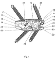
図4は、図3による実施形態を示す斜視図である。
(Brief description of the drawings)
FIG. 1 is an exploded view showing an embodiment of an intervertebral implant according to the present invention.
FIG. 2 is a perspective view showing the assembled embodiment of the intervertebral implant according to the present invention shown in FIG.
FIG. 3 is a side view of another embodiment of an intervertebral implant according to the present invention.
FIG. 4 is a perspective view showing the embodiment according to FIG.
図1および図2では、本発明による椎間インプラント1の実施形態が示されているが、これは隣接した椎体の底板への配置のために中心軸2に対して斜めに配置された上方の添加面15と、隣接した椎体の蓋板への配置のために中心軸2に対して斜めに配置された添加面25と、2つの関節38、39とを含んで成る。上部10および下部20は、関節38、39を通じて互いに対して可動接続されており、ここで下部20に対する上部10の可動性は、中心軸2に対して斜めに配置された第1の回転軸3の周りで+10°ないし−6°の角度範囲に制限され、かつ中心軸2に対して斜めに、第1の回転軸に対して垂直に配置された回転軸4の周りで±7°の角度範囲で制限されている。
両方の関節38、39は3つの関節31、32、33によって実現され、それによって下関節部品33および上関節部品31がそれぞれ中央関節部品32とともに作用する関節38、39を形成する。関節38、39はそれぞれ回転軸3、4を有し、ここで回転軸は互いに垂直に、かつ中心軸2に対して垂直に立っている。下関節39は、中央関節部品32に配置され、第1の回転軸3に対して同軸の、2分軸36と、下関節部品33に配置された、軸36を受入れる2つのベアリングシェルを含んで成る。上関節38は、上関節部品31に配置された、第2の回転軸4に対して同軸34と、中央関節部品32に配置された、軸34を受入れるベアリングシェル35とから成る。ベアリングシェル35、37、および軸34、36は溝71を有し、これはそれぞれの回転軸3、4に対して直交に見た断面で回転軸3,4に対して円弧状に配置されており、転動体70として球を受入れるために役立つ。
1 and 2, an embodiment of an
Both joints 38, 39 are realized by three
さらに、軸34、36には末端で回転軸3、4に対して同軸のカムが備えられており、これは下関節部品および中央関節部品32の縦長穴ガイド91へ摺動式に受入れられる。縦長穴ガイド91へ誘導されたカム90によって、関節部品31、32、33の回転軸は回転軸3、4の周りで制限される。また、椎間インプラント1は、縦長穴ガイド91へ受入れられるカム90によって結合される。
両方の部分10、20の互いに対する可動性は、手段40によって着脱自在に遮断可能である。手段40は、ここに示されている実施形態では、両方の部分10、20の腹側面11、21から中心軸に対して斜めに、かつ両方の部分10、20の外側面13、14、23、24に対して平行に挿入可能な挿入部41を含んで成る。挿入部41の挿入は、蟻形ガイドとして形成されている2つの凹み42、43において行われる。挿入部41は、両方の部分10、20の腹側面11、21から蟻形ガイドとして構成された凹み42、43へ導入され、下部20にネジ44によって固定される。また、挿入部41は末端で凹み42、43に補助的に構成されており、両方の部分10、20は挿入部41が挿入された場合に中心軸2に対して平行に互いに対して固定される。
Furthermore, the
The mobility of both
図3には本発明による椎間インプラント1の実施形態が示されているが、これは図1および図2に示されている実施形態とは、両方の部分10、20が骨固定手段81を受入れるための穴80を含んで成り、ここで骨固定手段80が骨ネジとして構成されているという点でのみ区別される。穴80は、中心軸とともに角度γを含む長手方向軸83を有する。さらに、両方の部分10、20の1つのそれぞれ2つの穴80(図4)が、腹側面11:21から添加面15、25まで貫通している。穴80の長手方向軸83は、外側から見ると中心軸2に対して斜めに立っているにすぎない。さらに、穴80は円錐状であり、添加面15、25に向かって先細に構成され、雌ネジ82を備えており、これらは骨ネジとして形成されている骨固定手段81の補助的な雄ネジが備えられたネジ頭84をネジ込み可能に受入れるために役立つ。
図4に示されている本発明による椎間インプラント1の実施形態は、穴80の長手方向軸83がさらに腹側から見ると両方の部分10、20の内面15、26から添加面15、25に向かって分岐する点でのみ図3に示されている実施形態と区別される。
FIG. 3 shows an embodiment of an
The embodiment of the
1 椎間インプラント 2 中心軸 3、4 回転軸
10 上部 11 腹側面 12 背側面
13、14 外側面 15 上添加面 16 下面
20 下部 21 腹側面 22 背側面
23、24 外側面 25 下添加面 26 上面
31 上関節部品 32 中央関節部品 33 下関節部品
34、36 軸 35、37 ベアリングシェル
38、39 関節 70 転動体
DESCRIPTION OF
Claims (20)
A)前記上部(10)が、腹側面(11)と、背側面(12)と、2つの外側面(13、14)と、上添加面(15)と、下表面(16)とを有し、
B)前記下部(20)が、腹側面(21)と、背側面(22)と、2つの外側面(23、24)と、下添加面(25)と、上表面(26)とを有し、
C)前記両方の部分(10、20)が前記両方の部分(10、20)間に配置された2つの関節(38、39)によって互いに対して可動であり、
D)前記関節(38、39)のそれぞれが回転軸(3、4)を有し、かつ両方の回転軸(3、4)が互いに横切って配置されており、
E)前記両方の関節(38、39)が、上部(10)と結合した上関節部品(31)と、中央関節部品(32)と、下部(20)と結合した下関節部品(33)とによって実現されており、
F)各関節(38、39)が、前記回転軸(3、4)に対して同軸の軸(34、36)の少なくとも1つを有する第1の関節部品(31、32、33)と、前記軸(34、36)を受入れるベアリングシェル(35、37)の少なくとも1つを有する第2の関節部品(31、32、33)とを含んで成る椎間インプラント(1)において、
G)前記軸(34、36)と前記ベアリングシェル(35、37)との間に転動体(70)が挿入されていることを特徴とする椎間インプラント(1)。The intervertebral implant (1) is suitable for placement on the central axis (2), the upper part (10) suitable for placement on the bottom plate of the vertebral body located above it and the lid plate for the vertebral body located below it An artificial intervertebral disc having a lower part (20),
A) The upper part (10) has a ventral side surface (11), a back side surface (12), two outer side surfaces (13, 14), an upper addition surface (15), and a lower surface (16). And
B) The lower part (20) has a ventral side surface (21), a back side surface (22), two outer side surfaces (23, 24), a lower addition surface (25), and an upper surface (26). And
C) the two parts (10, 20) are movable relative to each other by means of two joints (38, 39) arranged between the two parts (10, 20);
D) each of the joints (38, 39) has a rotation axis (3, 4) and both rotation axes (3, 4) are arranged across each other;
E) Both joints (38, 39) have an upper joint part (31) coupled to the upper part (10), a central joint part (32) and a lower joint part (33) joined to the lower part (20). Is realized by
F) a first joint component (31, 32, 33) in which each joint (38, 39) has at least one of the axes (34, 36) coaxial with said rotational axis (3, 4); An intervertebral implant (1) comprising a second articulating component (31, 32, 33) having at least one bearing shell (35, 37) for receiving said shaft (34, 36);
G) Intervertebral implant (1), wherein rolling elements (70) are inserted between the shafts (34, 36) and the bearing shells (35, 37).
Applications Claiming Priority (1)
| Application Number | Priority Date | Filing Date | Title |
|---|---|---|---|
| PCT/CH2002/000704 WO2004054475A1 (en) | 2002-12-17 | 2002-12-17 | Intervertebral implant with joint parts mounted on roller bodies |
Publications (3)
| Publication Number | Publication Date |
|---|---|
| JP2006509560A JP2006509560A (en) | 2006-03-23 |
| JP2006509560A5 JP2006509560A5 (en) | 2006-05-11 |
| JP4210651B2 true JP4210651B2 (en) | 2009-01-21 |
Family
ID=32514197
Family Applications (1)
| Application Number | Title | Priority Date | Filing Date |
|---|---|---|---|
| JP2004559543A Expired - Fee Related JP4210651B2 (en) | 2002-12-17 | 2002-12-17 | Intervertebral implant having joint parts mounted on rolling elements |
Country Status (16)
| Country | Link |
|---|---|
| US (1) | US7473276B2 (en) |
| EP (1) | EP1572036B1 (en) |
| JP (1) | JP4210651B2 (en) |
| KR (1) | KR101026936B1 (en) |
| CN (1) | CN100400016C (en) |
| AR (1) | AR042503A1 (en) |
| AT (1) | ATE394084T1 (en) |
| AU (1) | AU2002347116B2 (en) |
| BR (1) | BR0215965B1 (en) |
| CA (1) | CA2510242A1 (en) |
| DE (1) | DE50212247D1 (en) |
| ES (1) | ES2306797T3 (en) |
| HU (1) | HUP0500850A2 (en) |
| NZ (1) | NZ540265A (en) |
| TW (1) | TW200501925A (en) |
| WO (1) | WO2004054475A1 (en) |
Families Citing this family (156)
| Publication number | Priority date | Publication date | Assignee | Title |
|---|---|---|---|---|
| FR2897259B1 (en) | 2006-02-15 | 2008-05-09 | Ldr Medical Soc Par Actions Si | INTERSOMATIC TRANSFORAMINAL CAGE WITH INTERBREBAL FUSION GRAFT AND CAGE IMPLANTATION INSTRUMENT |
| CN100566678C (en) * | 2003-07-22 | 2009-12-09 | 斯恩蒂斯有限公司 | The intervertebral implant that has interim locking device |
| US7909869B2 (en) | 2003-08-05 | 2011-03-22 | Flexuspine, Inc. | Artificial spinal unit assemblies |
| US7753958B2 (en) | 2003-08-05 | 2010-07-13 | Gordon Charles R | Expandable intervertebral implant |
| US7799082B2 (en) | 2003-08-05 | 2010-09-21 | Flexuspine, Inc. | Artificial functional spinal unit system and method for use |
| ATE508713T1 (en) | 2003-11-18 | 2011-05-15 | Zimmer Gmbh | DISC IMPLANT |
| US7217291B2 (en) * | 2003-12-08 | 2007-05-15 | St. Francis Medical Technologies, Inc. | System and method for replacing degenerated spinal disks |
| US20050187631A1 (en) * | 2004-01-27 | 2005-08-25 | Sdgi Holdings, Inc. | Prosthetic device |
| RU2354334C2 (en) | 2004-02-04 | 2009-05-10 | Лдр Медикаль | Intervertebral disc prosthesis |
| CA2556486C (en) * | 2004-02-20 | 2010-03-23 | Spinecore, Inc. | Artificial intervertebral disc having a universal joint |
| WO2006058221A2 (en) | 2004-11-24 | 2006-06-01 | Abdou Samy M | Devices and methods for inter-vertebral orthopedic device placement |
| US8696707B2 (en) | 2005-03-08 | 2014-04-15 | Zyga Technology, Inc. | Facet joint stabilization |
| US8147547B2 (en) * | 2005-04-29 | 2012-04-03 | Warsaw Orthopedic, Inc. | Spinal implant |
| FR2891135B1 (en) * | 2005-09-23 | 2008-09-12 | Ldr Medical Sarl | INTERVERTEBRAL DISC PROSTHESIS |
| US8118869B2 (en) * | 2006-03-08 | 2012-02-21 | Flexuspine, Inc. | Dynamic interbody device |
| GB0623801D0 (en) * | 2006-11-29 | 2007-01-10 | Surgicraft Ltd | Orthopaedic implants and prosthesis |
| US8715352B2 (en) | 2006-12-14 | 2014-05-06 | Depuy Spine, Inc. | Buckling disc replacement |
| US9066811B2 (en) | 2007-01-19 | 2015-06-30 | Flexuspine, Inc. | Artificial functional spinal unit system and method for use |
| FR2916956B1 (en) | 2007-06-08 | 2012-12-14 | Ldr Medical | INTERSOMATIC CAGE, INTERVERTEBRAL PROSTHESIS, ANCHORING DEVICE AND IMPLANTATION INSTRUMENTATION |
| US20080312742A1 (en) * | 2007-06-12 | 2008-12-18 | Dennis Lee Abernathie | Anterior Spinal Fusion and Fixation Cage with Integrated Plate and Method of Use |
| WO2009039171A2 (en) * | 2007-09-17 | 2009-03-26 | Linares Medical Devices, Llc | Artificial joint support between first and second bones |
| US8343189B2 (en) * | 2007-09-25 | 2013-01-01 | Zyga Technology, Inc. | Method and apparatus for facet joint stabilization |
| US8182514B2 (en) | 2007-10-22 | 2012-05-22 | Flexuspine, Inc. | Dampener system for a posterior stabilization system with a fixed length elongated member |
| US8187330B2 (en) | 2007-10-22 | 2012-05-29 | Flexuspine, Inc. | Dampener system for a posterior stabilization system with a variable length elongated member |
| US8267965B2 (en) | 2007-10-22 | 2012-09-18 | Flexuspine, Inc. | Spinal stabilization systems with dynamic interbody devices |
| US8162994B2 (en) | 2007-10-22 | 2012-04-24 | Flexuspine, Inc. | Posterior stabilization system with isolated, dual dampener systems |
| US8523912B2 (en) | 2007-10-22 | 2013-09-03 | Flexuspine, Inc. | Posterior stabilization systems with shared, dual dampener systems |
| WO2009055478A1 (en) * | 2007-10-22 | 2009-04-30 | Spinalmotion, Inc. | Vertebral body replacement and method for spanning a space formed upon removal of a vertebral body |
| US8157844B2 (en) | 2007-10-22 | 2012-04-17 | Flexuspine, Inc. | Dampener system for a posterior stabilization system with a variable length elongated member |
| EP2057971B1 (en) * | 2007-11-07 | 2010-06-09 | Gs Development Ab | Artificial joint |
| US8377132B2 (en) * | 2008-01-16 | 2013-02-19 | Aesculap Implant Systems, Llc | Standalone dynamic interbody |
| DE102009011648A1 (en) * | 2009-03-04 | 2010-09-09 | Advanced Medical Technologies Ag | Implant system with support elements |
| US9408715B2 (en) | 2009-04-15 | 2016-08-09 | DePuy Synthes Products, Inc. | Arcuate fixation member |
| US8641766B2 (en) | 2009-04-15 | 2014-02-04 | DePuy Synthes Products, LLC | Arcuate fixation member |
| CN101559003B (en) * | 2009-06-02 | 2011-07-20 | 北京纳通投资有限公司 | Artificial intervertebral disc |
| US8394125B2 (en) * | 2009-07-24 | 2013-03-12 | Zyga Technology, Inc. | Systems and methods for facet joint treatment |
| KR101805935B1 (en) | 2009-09-17 | 2017-12-06 | 엘디알 홀딩 코포레이션 | Intervertebral implant having extendable bone fixation members |
| US10098758B2 (en) | 2009-10-15 | 2018-10-16 | Globus Medical, Inc. | Expandable fusion device and method of installation thereof |
| US11344430B2 (en) | 2009-10-15 | 2022-05-31 | Globus Medical, Inc. | Expandable fusion device and method of installation thereof |
| US9155628B2 (en) | 2009-10-15 | 2015-10-13 | Globus Medical, Inc. | Expandable fusion device and method of installation thereof |
| US8685098B2 (en) | 2010-06-25 | 2014-04-01 | Globus Medical, Inc. | Expandable fusion device and method of installation thereof |
| US11564807B2 (en) | 2009-10-15 | 2023-01-31 | Globus Medical, Inc. | Expandable fusion device and method of installation thereof |
| US8062375B2 (en) | 2009-10-15 | 2011-11-22 | Globus Medical, Inc. | Expandable fusion device and method of installation thereof |
| US11103366B2 (en) | 2009-10-15 | 2021-08-31 | Globus Medical, Inc. | Expandable fusion device and method of installation thereof |
| US10806596B2 (en) | 2009-10-15 | 2020-10-20 | Globus Medical, Inc. | Expandable fusion device and method installation thereof |
| US8709086B2 (en) | 2009-10-15 | 2014-04-29 | Globus Medical, Inc. | Expandable fusion device and method of installation thereof |
| US10327917B2 (en) | 2009-10-15 | 2019-06-25 | Globus Medical, Inc. | Expandable fusion device and method of installation thereof |
| US8679183B2 (en) | 2010-06-25 | 2014-03-25 | Globus Medical | Expandable fusion device and method of installation thereof |
| US9216095B2 (en) | 2009-10-15 | 2015-12-22 | Globus Medical, Inc. | Expandable fusion device and method of installation thereof |
| US8556979B2 (en) | 2009-10-15 | 2013-10-15 | Globus Medical, Inc. | Expandable fusion device and method of installation thereof |
| US8764806B2 (en) | 2009-12-07 | 2014-07-01 | Samy Abdou | Devices and methods for minimally invasive spinal stabilization and instrumentation |
| JP5647264B2 (en) | 2009-12-31 | 2014-12-24 | エル・デ・エール・メデイカル | Fixation devices, intervertebral implants, and implantable devices |
| US8353963B2 (en) | 2010-01-12 | 2013-01-15 | Globus Medical | Expandable spacer and method for use thereof |
| US9913726B2 (en) | 2010-02-24 | 2018-03-13 | Globus Medical, Inc. | Expandable intervertebral spacer and method of posterior insertion thereof |
| CA2793185C (en) | 2010-03-16 | 2019-02-12 | Pinnacle Spine Group, Llc | Intervertebral implants and graft delivery systems and methods |
| US8870880B2 (en) | 2010-04-12 | 2014-10-28 | Globus Medical, Inc. | Angling inserter tool for expandable vertebral implant |
| US9301850B2 (en) | 2010-04-12 | 2016-04-05 | Globus Medical, Inc. | Expandable vertebral implant |
| US8663293B2 (en) | 2010-06-15 | 2014-03-04 | Zyga Technology, Inc. | Systems and methods for facet joint treatment |
| US9233006B2 (en) | 2010-06-15 | 2016-01-12 | Zyga Technology, Inc. | Systems and methods for facet joint treatment |
| US9597200B2 (en) | 2010-06-25 | 2017-03-21 | Globus Medical, Inc | Expandable fusion device and method of installation thereof |
| US10085849B2 (en) | 2010-09-03 | 2018-10-02 | Globus Medical, Inc. | Expandable fusion device and method of installation thereof |
| US10512550B2 (en) | 2010-09-03 | 2019-12-24 | Globus Medical, Inc. | Expandable interspinous process fixation device |
| US10945858B2 (en) | 2010-09-03 | 2021-03-16 | Globus Medical, Inc. | Expandable interspinous process fixation device |
| US8845734B2 (en) | 2010-09-03 | 2014-09-30 | Globus Medical, Inc. | Expandable fusion device and method of installation thereof |
| US10709573B2 (en) | 2010-09-03 | 2020-07-14 | Globus Medical Inc. | Expandable fusion device and method of installation thereof |
| US9351848B2 (en) | 2010-09-03 | 2016-05-31 | Globus Medical, Inc. | Expandable fusion device and method of installation thereof |
| US9474625B2 (en) | 2010-09-03 | 2016-10-25 | Globus Medical, Inc | Expandable fusion device and method of installation thereof |
| US11793654B2 (en) | 2010-09-03 | 2023-10-24 | Globus Medical, Inc. | Expandable fusion device and method of installation thereof |
| US9566168B2 (en) | 2010-09-03 | 2017-02-14 | Globus Medical, Inc. | Expandable fusion device and method of installation thereof |
| US8435298B2 (en) | 2010-09-03 | 2013-05-07 | Globus Medical, Inc. | Expandable fusion device and method of installation thereof |
| US8845732B2 (en) | 2010-09-03 | 2014-09-30 | Globus Medical, Inc. | Expandable fusion device and method of installation thereof |
| US10758367B2 (en) | 2010-09-03 | 2020-09-01 | Globus Medical Inc. | Expandable fusion device and method of installation thereof |
| US10869768B2 (en) | 2010-09-03 | 2020-12-22 | Globus Medical Inc. | Expandable fusion device and method of installation thereof |
| US10842644B2 (en) | 2010-09-03 | 2020-11-24 | Globus Medical, Inc. | Expandable fusion device and method of installation thereof |
| US8845731B2 (en) | 2010-09-03 | 2014-09-30 | Globus Medical, Inc. | Expandable fusion device and method of installation thereof |
| US9855151B2 (en) | 2010-09-03 | 2018-01-02 | Globus Medical, Inc | Expandable fusion device and method of installation thereof |
| US10835387B2 (en) | 2010-09-03 | 2020-11-17 | Globus Medical Inc. | Expandable fusion device and method of installation thereof |
| US9907673B2 (en) | 2010-09-03 | 2018-03-06 | Globus Medical, Inc. | Expandable fusion device and method of installation thereof |
| US8491659B2 (en) | 2010-09-03 | 2013-07-23 | Globus Medical, Inc. | Expandable fusion device and method of installation thereof |
| US10779957B2 (en) | 2010-09-03 | 2020-09-22 | Globus Medical, Inc. | Expandable fusion device and method of installation thereof |
| US8852279B2 (en) | 2010-09-03 | 2014-10-07 | Globus Medical, Inc. | Expandable fusion device and method of installation thereof |
| US8632595B2 (en) | 2010-09-03 | 2014-01-21 | Globus Medical, Inc. | Expandable fusion device and method of installation thereof |
| US11446162B2 (en) | 2010-09-03 | 2022-09-20 | Globus Medical, Inc. | Expandable fusion device and method of installation thereof |
| US8491641B2 (en) | 2010-09-28 | 2013-07-23 | Spinofix, Inc. | Pedicle screws and dynamic adaptors |
| US20120150300A1 (en) * | 2010-12-08 | 2012-06-14 | Raj Nihalani | Inter-vertebral-body spacer |
| US9358122B2 (en) | 2011-01-07 | 2016-06-07 | K2M, Inc. | Interbody spacer |
| US8545563B2 (en) | 2011-02-02 | 2013-10-01 | DePuy Synthes Product, LLC | Intervertebral implant having extendable bone fixation members |
| US8388687B2 (en) | 2011-03-25 | 2013-03-05 | Flexuspine, Inc. | Interbody device insertion systems and methods |
| US8845728B1 (en) | 2011-09-23 | 2014-09-30 | Samy Abdou | Spinal fixation devices and methods of use |
| US8864833B2 (en) | 2011-09-30 | 2014-10-21 | Globus Medical, Inc. | Expandable fusion device and method of installation thereof |
| US9380932B1 (en) | 2011-11-02 | 2016-07-05 | Pinnacle Spine Group, Llc | Retractor devices for minimally invasive access to the spine |
| US9526627B2 (en) | 2011-11-17 | 2016-12-27 | Exactech, Inc. | Expandable interbody device system and method |
| US20130226240A1 (en) | 2012-02-22 | 2013-08-29 | Samy Abdou | Spinous process fixation devices and methods of use |
| US9198767B2 (en) | 2012-08-28 | 2015-12-01 | Samy Abdou | Devices and methods for spinal stabilization and instrumentation |
| US9962261B1 (en) * | 2012-10-19 | 2018-05-08 | Aptis Medical, Llc | Prosthesis including ball and socket arrangement |
| US9320617B2 (en) | 2012-10-22 | 2016-04-26 | Cogent Spine, LLC | Devices and methods for spinal stabilization and instrumentation |
| EP2919717A1 (en) | 2012-11-15 | 2015-09-23 | Zyga Technology, Inc. | Systems and methods for facet joint treatment |
| US10299934B2 (en) | 2012-12-11 | 2019-05-28 | Globus Medical, Inc | Expandable vertebral implant |
| US10350081B2 (en) | 2012-12-11 | 2019-07-16 | Globus Medical, Inc. | Expandable vertebral implant |
| US9011493B2 (en) | 2012-12-31 | 2015-04-21 | Globus Medical, Inc. | Spinous process fixation system and methods thereof |
| US9402738B2 (en) | 2013-02-14 | 2016-08-02 | Globus Medical, Inc. | Devices and methods for correcting vertebral misalignment |
| US9782265B2 (en) | 2013-02-15 | 2017-10-10 | Globus Medical, Inc | Articulating and expandable vertebral implant |
| US9492288B2 (en) | 2013-02-20 | 2016-11-15 | Flexuspine, Inc. | Expandable fusion device for positioning between adjacent vertebral bodies |
| US10117754B2 (en) | 2013-02-25 | 2018-11-06 | Globus Medical, Inc. | Expandable intervertebral implant |
| US9554918B2 (en) | 2013-03-01 | 2017-01-31 | Globus Medical, Inc. | Articulating expandable intervertebral implant |
| US9770343B2 (en) | 2013-03-01 | 2017-09-26 | Globus Medical Inc. | Articulating expandable intervertebral implant |
| US9198772B2 (en) | 2013-03-01 | 2015-12-01 | Globus Medical, Inc. | Articulating expandable intervertebral implant |
| US10004607B2 (en) | 2013-03-01 | 2018-06-26 | Globus Medical, Inc. | Articulating expandable intervertebral implant |
| US9204972B2 (en) | 2013-03-01 | 2015-12-08 | Globus Medical, Inc. | Articulating expandable intervertebral implant |
| WO2014159739A1 (en) | 2013-03-14 | 2014-10-02 | Pinnacle Spine Group, Llc | Interbody implants and graft delivery systems |
| US9233009B2 (en) | 2013-03-15 | 2016-01-12 | Globus Medical, Inc. | Expandable intervertebral implant |
| US9456906B2 (en) | 2013-03-15 | 2016-10-04 | Globus Medical, Inc. | Expandable intervertebral implant |
| US9149367B2 (en) | 2013-03-15 | 2015-10-06 | Globus Medical Inc | Expandable intervertebral implant |
| US9186258B2 (en) | 2013-03-15 | 2015-11-17 | Globus Medical, Inc. | Expandable intervertebral implant |
| US9539103B2 (en) | 2013-03-15 | 2017-01-10 | Globus Medical, Inc. | Expandable intervertebral implant |
| US9572677B2 (en) * | 2013-03-15 | 2017-02-21 | Globus Medical, Inc. | Expandable intervertebral implant |
| US9034045B2 (en) * | 2013-03-15 | 2015-05-19 | Globus Medical, Inc | Expandable intervertebral implant |
| EP2967908B1 (en) * | 2013-03-15 | 2021-03-10 | Globus Medical, Inc. | Expandable intervertebral implant |
| FR3005569B1 (en) | 2013-05-16 | 2021-09-03 | Ldr Medical | VERTEBRAL IMPLANT, VERTEBRAL IMPLANT FIXATION DEVICE AND IMPLANTATION INSTRUMENTATION |
| US9662224B2 (en) | 2014-02-07 | 2017-05-30 | Globus Medical, Inc. | Variable lordosis spacer and related methods of use |
| US9839528B2 (en) | 2014-02-07 | 2017-12-12 | Globus Medical, Inc. | Variable lordosis spacer and related methods of use |
| US9402739B2 (en) | 2014-02-07 | 2016-08-02 | Globus Medical, Inc. | Variable lordosis spacer and related methods of use |
| US9517144B2 (en) | 2014-04-24 | 2016-12-13 | Exactech, Inc. | Limited profile intervertebral implant with incorporated fastening mechanism |
| US10398565B2 (en) | 2014-04-24 | 2019-09-03 | Choice Spine, Llc | Limited profile intervertebral implant with incorporated fastening and locking mechanism |
| FR3020756B1 (en) | 2014-05-06 | 2022-03-11 | Ldr Medical | VERTEBRAL IMPLANT, VERTEBRAL IMPLANT FIXATION DEVICE AND IMPLANT INSTRUMENTATION |
| US9901459B2 (en) | 2014-12-16 | 2018-02-27 | Globus Medical, Inc. | Expandable fusion devices and methods of installation thereof |
| US10433975B2 (en) | 2015-05-21 | 2019-10-08 | Globus Medical, Inc. | Device and method for deployment of an anchoring device for intervertebral spinal fusion |
| US10765532B2 (en) | 2015-05-21 | 2020-09-08 | Globus Medical, Inc. | Device and method for deployment of an anchoring device for intervertebral spinal fusion |
| US10376378B2 (en) | 2015-05-21 | 2019-08-13 | Globus Medical, Inc. | Device and method for deployment of an anchoring device for intervertebral spinal fusion |
| US9848996B2 (en) | 2015-06-17 | 2017-12-26 | Globus Medical, Inc. | Variable lordotic interbody spacer |
| US10016282B2 (en) | 2015-07-17 | 2018-07-10 | Globus Medical, Inc. | Intervertebral spacer and plate |
| US10034768B2 (en) | 2015-09-02 | 2018-07-31 | Globus Medical, Inc. | Implantable systems, devices and related methods |
| US10857003B1 (en) | 2015-10-14 | 2020-12-08 | Samy Abdou | Devices and methods for vertebral stabilization |
| US10219914B2 (en) | 2015-11-10 | 2019-03-05 | Globus Medical, Inc. | Stabilized expandable intervertebral spacer |
| US20170156884A1 (en) * | 2015-12-07 | 2017-06-08 | Ctl Medical Corporation | Plate cage system with standalone effects and related methods |
| US10369004B2 (en) * | 2015-12-16 | 2019-08-06 | Globus Medical, Inc. | Expandable intervertebralspacer |
| US10052215B2 (en) | 2016-06-29 | 2018-08-21 | Globus Medical, Inc. | Expandable fusion device and method of installation thereof |
| US9974662B2 (en) | 2016-06-29 | 2018-05-22 | Globus Medical, Inc. | Expandable fusion device and method of installation thereof |
| US9883953B1 (en) * | 2016-09-21 | 2018-02-06 | Integrity Implants Inc. | Stabilized laterovertically-expanding fusion cage systems with tensioner |
| US10744000B1 (en) | 2016-10-25 | 2020-08-18 | Samy Abdou | Devices and methods for vertebral bone realignment |
| US10973648B1 (en) | 2016-10-25 | 2021-04-13 | Samy Abdou | Devices and methods for vertebral bone realignment |
| US11896494B2 (en) | 2017-07-10 | 2024-02-13 | Life Spine, Inc. | Expandable implant assembly |
| US11179248B2 (en) | 2018-10-02 | 2021-11-23 | Samy Abdou | Devices and methods for spinal implantation |
| US11382764B2 (en) | 2019-06-10 | 2022-07-12 | Life Spine, Inc. | Expandable implant assembly with compression features |
| US11259933B2 (en) | 2019-09-06 | 2022-03-01 | Globus Medical Inc. | Expandable motion preservation spacer |
| US11191650B2 (en) | 2020-02-03 | 2021-12-07 | Globus Medical Inc. | Expandable fusions devices, instruments, and methods thereof |
| US11291553B2 (en) * | 2020-03-05 | 2022-04-05 | Phoenyx Spinal Technologies, Inc. | Interlocking spinal disc prosthetic |
| US11857432B2 (en) | 2020-04-13 | 2024-01-02 | Life Spine, Inc. | Expandable implant assembly |
| US11602439B2 (en) | 2020-04-16 | 2023-03-14 | Life Spine, Inc. | Expandable implant assembly |
| US11298240B2 (en) | 2020-06-16 | 2022-04-12 | Globus Medical, Inc. | Expanding intervertebral implants |
| US11602440B2 (en) * | 2020-06-25 | 2023-03-14 | Life Spine, Inc. | Expandable implant assembly |
| US11357640B2 (en) | 2020-07-08 | 2022-06-14 | Globus Medical Inc. | Expandable interbody fusions devices |
| US11491020B2 (en) | 2020-07-09 | 2022-11-08 | Globus Medical, Inc. | Articulating and expandable interbody fusions devices |
| US11554020B2 (en) | 2020-09-08 | 2023-01-17 | Life Spine, Inc. | Expandable implant with pivoting control assembly |
| US11896499B2 (en) | 2021-12-02 | 2024-02-13 | Globus Medical, Inc | Expandable fusion device with integrated deployable retention spikes |
| US11883080B1 (en) | 2022-07-13 | 2024-01-30 | Globus Medical, Inc | Reverse dynamization implants |
Family Cites Families (14)
| Publication number | Priority date | Publication date | Assignee | Title |
|---|---|---|---|---|
| ATE44871T1 (en) | 1984-09-04 | 1989-08-15 | Univ Berlin Humboldt | DISC PROSTHESIS. |
| DE9304368U1 (en) * | 1993-03-18 | 1993-05-13 | Aap Gmbh & Co. Betriebs Kg, 1000 Berlin, De | |
| US5893889A (en) * | 1997-06-20 | 1999-04-13 | Harrington; Michael | Artificial disc |
| DE19750382A1 (en) * | 1997-11-13 | 1999-05-20 | Augustin Prof Dr Med Betz | Operative correction equipment for displaced vertebrae used in minimally invasive surgery |
| DE19807236C2 (en) * | 1998-02-20 | 2000-06-21 | Biedermann Motech Gmbh | Intervertebral implant |
| ES2213275T3 (en) * | 1998-05-19 | 2004-08-16 | Synthes Ag Chur | OSTEOSYNTHETIC IMPLANT EQUIPPED WITH AN ENCASTERED COUPLING. |
| CN2332369Y (en) * | 1998-06-19 | 1999-08-11 | 顾家富 | Womb expending device |
| US5989294A (en) * | 1998-07-29 | 1999-11-23 | Marlow; Aaron L. | Ball-and-socket joint, particularly a prosthetic hip joint |
| FR2794640B1 (en) * | 1999-06-11 | 2001-09-07 | Hubert Hellak | KNEE JOINT PROSTHESIS |
| FR2797179B1 (en) | 1999-08-03 | 2002-03-08 | Michel Gau | INTERVERTEBRAL NUCLEAR PROSTHESIS AND SURGICAL IMPLANTATION METHOD |
| EP1645248B8 (en) * | 2000-02-04 | 2010-06-16 | Warsaw Orthopedic, Inc. | Expandable interbody spinal fusion implant having pivotally attached blocker |
| US6610093B1 (en) * | 2000-07-28 | 2003-08-26 | Perumala Corporation | Method and apparatus for stabilizing adjacent vertebrae |
| US7273496B2 (en) * | 2002-10-29 | 2007-09-25 | St. Francis Medical Technologies, Inc. | Artificial vertebral disk replacement implant with crossbar spacer and method |
| WO2004041131A2 (en) * | 2002-10-31 | 2004-05-21 | Spinal Concepts, Inc. | Movable disc implant |
-
2002
- 2002-12-17 WO PCT/CH2002/000704 patent/WO2004054475A1/en active IP Right Grant
- 2002-12-17 AU AU2002347116A patent/AU2002347116B2/en not_active Ceased
- 2002-12-17 CN CNB028300718A patent/CN100400016C/en not_active Expired - Fee Related
- 2002-12-17 JP JP2004559543A patent/JP4210651B2/en not_active Expired - Fee Related
- 2002-12-17 DE DE50212247T patent/DE50212247D1/en not_active Expired - Lifetime
- 2002-12-17 US US10/539,659 patent/US7473276B2/en not_active Expired - Lifetime
- 2002-12-17 CA CA002510242A patent/CA2510242A1/en not_active Abandoned
- 2002-12-17 EP EP02782615A patent/EP1572036B1/en not_active Expired - Lifetime
- 2002-12-17 NZ NZ540265A patent/NZ540265A/en not_active IP Right Cessation
- 2002-12-17 AT AT02782615T patent/ATE394084T1/en not_active IP Right Cessation
- 2002-12-17 HU HU0500850A patent/HUP0500850A2/en unknown
- 2002-12-17 BR BRPI0215965-1A patent/BR0215965B1/en not_active IP Right Cessation
- 2002-12-17 ES ES02782615T patent/ES2306797T3/en not_active Expired - Lifetime
- 2002-12-17 KR KR1020057011460A patent/KR101026936B1/en not_active IP Right Cessation
-
2003
- 2003-11-28 TW TW092133513A patent/TW200501925A/en not_active IP Right Cessation
- 2003-12-17 AR ARP030104675A patent/AR042503A1/en unknown
Also Published As
| Publication number | Publication date |
|---|---|
| NZ540265A (en) | 2006-04-28 |
| BR0215965A (en) | 2005-09-27 |
| AR042503A1 (en) | 2005-06-22 |
| KR20050092719A (en) | 2005-09-22 |
| TW200501925A (en) | 2005-01-16 |
| US7473276B2 (en) | 2009-01-06 |
| CA2510242A1 (en) | 2004-07-01 |
| EP1572036B1 (en) | 2008-05-07 |
| ATE394084T1 (en) | 2008-05-15 |
| ES2306797T3 (en) | 2008-11-16 |
| AU2002347116A1 (en) | 2004-07-09 |
| EP1572036A1 (en) | 2005-09-14 |
| US20070135919A1 (en) | 2007-06-14 |
| KR101026936B1 (en) | 2011-04-04 |
| TWI321049B (en) | 2010-03-01 |
| DE50212247D1 (en) | 2008-06-19 |
| JP2006509560A (en) | 2006-03-23 |
| HUP0500850A2 (en) | 2006-04-28 |
| WO2004054475A1 (en) | 2004-07-01 |
| AU2002347116B2 (en) | 2006-10-26 |
| BR0215965B1 (en) | 2012-08-21 |
| CN1713868A (en) | 2005-12-28 |
| CN100400016C (en) | 2008-07-09 |
Similar Documents
| Publication | Publication Date | Title |
|---|---|---|
| JP4210651B2 (en) | Intervertebral implant having joint parts mounted on rolling elements | |
| JP4276625B2 (en) | Intervertebral implants with joints arranged in a cardan fashion | |
| JP4210652B2 (en) | Intervertebral implant with tiltable joint parts | |
| JP2006509563A (en) | Intervertebral implant | |
| JP4210653B2 (en) | Intervertebral implant | |
| US7025787B2 (en) | Implantable joint prosthesis and associated instrumentation | |
| US8070816B2 (en) | Arthroplasty spinal prosthesis and insertion device | |
| JP4210648B2 (en) | Implant with a two-part joint | |
| JP2008509792A (en) | Intervertebral disc system | |
| US8182536B2 (en) | Total disc replacement device | |
| JP2006509560A5 (en) | ||
| AU2002346524A1 (en) | Implantable joint prosthesis and associated instrumentation | |
| CA2726642A1 (en) | Articulating disc implant | |
| NZ540229A (en) | Intervertebral implant with tiltable joint parts | |
| ZA200504799B (en) | Intervertebral implant with tiltable joint parts. | |
| ZA200504802B (en) | Intervertebral implant. | |
| ZA200504800B (en) | Intervertebral implant comprising joint parts that are mounted to form a universal joint |
Legal Events
| Date | Code | Title | Description |
|---|---|---|---|
| A521 | Request for written amendment filed |
Free format text: JAPANESE INTERMEDIATE CODE: A523 Effective date: 20051209 |
|
| A621 | Written request for application examination |
Free format text: JAPANESE INTERMEDIATE CODE: A621 Effective date: 20051209 |
|
| A521 | Request for written amendment filed |
Free format text: JAPANESE INTERMEDIATE CODE: A523 Effective date: 20060203 |
|
| A711 | Notification of change in applicant |
Free format text: JAPANESE INTERMEDIATE CODE: A711 Effective date: 20060614 |
|
| RD02 | Notification of acceptance of power of attorney |
Free format text: JAPANESE INTERMEDIATE CODE: A7422 Effective date: 20080117 |
|
| A131 | Notification of reasons for refusal |
Free format text: JAPANESE INTERMEDIATE CODE: A131 Effective date: 20080606 |
|
| A521 | Request for written amendment filed |
Free format text: JAPANESE INTERMEDIATE CODE: A523 Effective date: 20080905 |
|
| TRDD | Decision of grant or rejection written | ||
| A01 | Written decision to grant a patent or to grant a registration (utility model) |
Free format text: JAPANESE INTERMEDIATE CODE: A01 Effective date: 20081001 |
|
| A01 | Written decision to grant a patent or to grant a registration (utility model) |
Free format text: JAPANESE INTERMEDIATE CODE: A01 |
|
| A61 | First payment of annual fees (during grant procedure) |
Free format text: JAPANESE INTERMEDIATE CODE: A61 Effective date: 20081027 |
|
| R150 | Certificate of patent or registration of utility model |
Free format text: JAPANESE INTERMEDIATE CODE: R150 |
|
| FPAY | Renewal fee payment (event date is renewal date of database) |
Free format text: PAYMENT UNTIL: 20111031 Year of fee payment: 3 |
|
| FPAY | Renewal fee payment (event date is renewal date of database) |
Free format text: PAYMENT UNTIL: 20121031 Year of fee payment: 4 |
|
| FPAY | Renewal fee payment (event date is renewal date of database) |
Free format text: PAYMENT UNTIL: 20131031 Year of fee payment: 5 |
|
| R250 | Receipt of annual fees |
Free format text: JAPANESE INTERMEDIATE CODE: R250 |
|
| R250 | Receipt of annual fees |
Free format text: JAPANESE INTERMEDIATE CODE: R250 |
|
| LAPS | Cancellation because of no payment of annual fees |