JP4209158B2 - Switching device for a device for transmitting and receiving electromagnetic waves - Google Patents
Switching device for a device for transmitting and receiving electromagnetic waves Download PDFInfo
- Publication number
- JP4209158B2 JP4209158B2 JP2002256730A JP2002256730A JP4209158B2 JP 4209158 B2 JP4209158 B2 JP 4209158B2 JP 2002256730 A JP2002256730 A JP 2002256730A JP 2002256730 A JP2002256730 A JP 2002256730A JP 4209158 B2 JP4209158 B2 JP 4209158B2
- Authority
- JP
- Japan
- Prior art keywords
- slot
- antenna
- diode
- printed
- switching device
- Prior art date
- Legal status (The legal status is an assumption and is not a legal conclusion. Google has not performed a legal analysis and makes no representation as to the accuracy of the status listed.)
- Expired - Fee Related
Links
Images


Classifications
-
- H—ELECTRICITY
- H01—ELECTRIC ELEMENTS
- H01Q—ANTENNAS, i.e. RADIO AERIALS
- H01Q21/00—Antenna arrays or systems
- H01Q21/06—Arrays of individually energised antenna units similarly polarised and spaced apart
- H01Q21/20—Arrays of individually energised antenna units similarly polarised and spaced apart the units being spaced along or adjacent to a curvilinear path
- H01Q21/205—Arrays of individually energised antenna units similarly polarised and spaced apart the units being spaced along or adjacent to a curvilinear path providing an omnidirectional coverage
-
- H—ELECTRICITY
- H01—ELECTRIC ELEMENTS
- H01Q—ANTENNAS, i.e. RADIO AERIALS
- H01Q13/00—Waveguide horns or mouths; Slot antennas; Leaky-waveguide antennas; Equivalent structures causing radiation along the transmission path of a guided wave
- H01Q13/08—Radiating ends of two-conductor microwave transmission lines, e.g. of coaxial lines, of microstrip lines
- H01Q13/085—Slot-line radiating ends
-
- H—ELECTRICITY
- H01—ELECTRIC ELEMENTS
- H01Q—ANTENNAS, i.e. RADIO AERIALS
- H01Q3/00—Arrangements for changing or varying the orientation or the shape of the directional pattern of the waves radiated from an antenna or antenna system
- H01Q3/24—Arrangements for changing or varying the orientation or the shape of the directional pattern of the waves radiated from an antenna or antenna system varying the orientation by switching energy from one active radiating element to another, e.g. for beam switching
- H01Q3/242—Circumferential scanning
Description
【0001】
【発明の属する技術分野】
本発明は、信号を送受信する装置用のスイッチング装置に係り、特に、無線伝送の分野で使用されるスイッチング装置に関する。
【0002】
【従来の技術】
特に、家庭内の環境で使用される従来の高スループット無線伝送システムにおいて、送信機によって送信された信号は、複数の別々のパスに沿って受信機へ到達する。このため、受信機側では、送信信号にフェージングと歪みを生じさせる可能性のある干渉が発生し、その結果として、伝送されるべき情報が損失或いは劣化する。この欠点を克服するため、ホーン型、反射型若しくはアレイ型の指向性アンテナが一般的に使用される。これらのアンテナは、送受信に使用され、マルチパスに関連した劣化に効果があり、或いは、劣化を軽減し得る。特に、指向性アンテナによって得られる利得とは別に、指向性アンテナは、空間フィルタリングによって、一方で、マルチパスの数を減少させ、その結果として、フェージングの量を減少させ、他方で、同一周波数帯域で動作している他のシステムとの干渉を低減させることができる。
【0003】
指向性アンテナは、空間方位カバレッジ(受信可能範囲)を広くすることができないので、本願と同一出願人による仏国特許第00 15715号明細書には、ビバルディ型アンテナに基づく小形組立式アンテナが提案されている。このアンテナは、n個のビバルディ・アンテナ型印刷放射素子の同心円状配置(nは2より大きい数)を含み、幾つかの指向性ビームを時間的に順番に与えることができる。ビームの組によって空間の360°全体(全方位)の範囲を受け持つことか可能になる。
【0004】
スイッチング動作は、アンテナ外部に取り付けられたスイッチによって行われる。一般的に、このスイッチは、電力加算/分配回路と組み合わされたダイオードと、少なくともn個のポートを具備した制御電子部品とにより構成され、n個の素子の中から一つ以上のビバルディ・アンテナを選択することが可能である。マッチングに関して許容可能な性能を保証するため、屡々、2個以上のダイオードがポート上で使用される。さらに、電力加算/分配回路からの損失が、ビバルディ・アンテナを励振するため必要なスロットライン−マイクロストリップライン変化のカップリング損失に加わる。最後に、ダイオード状態(オン又はオフ)はバイアス電圧によって制御される。各ポートに与えら得た電圧を分離できるようにするため、DC電流を阻止する回路(DC阻止)が使用される。このため、更なる損失が生じる。
【0005】
【発明が解決しようとする課題】
このように、スイッチング機能は、屡々、ダイオードの価格、生産コスト、並びに、バイアス用回路及び電力加算/分配回路のための大型化の結果として高価である。さらに、スイッチング機能は、僅かな電力損失を生ずるのではなく、分配/加算回路における損失、DC阻止における損失、及び、ダイオードにおける損失を生じる。これらの損失のため、受信時に、受信機のノイズ温度が上昇し、送信時に、送信電力のドライロスが生じ、電力増幅器を過剰に大きくする必要があり、著しいコスト増加を招く。
【0006】
したがって、本発明は、コスト、全体的なサイズ、及び、様々な損失を減少させることができる、信号を送受信する装置用のスイッチング装置の提供を目的とする。
【0007】
【課題を解決するための手段】
本発明の対象は、信号を送受信する装置である。この装置は、
nが1以上の整数を表わすとき、スロットアンテナ型の長手方向放射で波を送受信するn個の手段の組立体と、
少なくとも一つのアンテナのスロットに電磁気的に接続された励振手段と、
励振手段とスロットアンテナの少なくとも一つのスロットとの間の電磁カップリングを制御することにより動作するスイッチング装置と、
を有する装置であって、
スイッチング装置は、
スロットアンテナの一つのスロットを画成する二つの金属表面間に可逆電気接点を形成する少なくとも一つの手段(尚、これは、ダイオードを含む)と、
上記可逆電気接点の状態を制御する手段と、
を具備することを特徴とする、装置である。
【0008】
一実施例によれば、励振手段は、マイクロストリップ型電源ラインにより構成される。一変形例によれば、励振手段は、共平面型ラインにより構成される。
【0009】
他の実施例によれば、スロットアンテナは、基板に印刷された少なくとも一つのスロットを含み、このスロットの一端は、この基板の縁に向かって徐々に広がり、このスロットの他端は、同様に閉じていないが、基板の別の縁へ延びる。
【0010】
他の実施例によれば、スロットアンテナは、単一の共平面点の周りに規則的に配置されるので、360°の全方位領域に放射する。
【0011】
【発明の実施の形態】
本発明のその他の特徴及び利点は、添付図面を参照して以下の種々の実施例の記載を読むことにより明らかになる。
【0012】
図1は、基板3に印刷されたビバルディ型アンテナの概略図である。ビバルディ型アンテナの構造及び性能は、当業者に周知であり、特に、文献:S. Prasad and S.Mahpara, "IEEE Transactions on Antennas and Propagaton", Voluem 2, AP-31, No.3, May 1983、及び、文献:A. Louzir, R. Clequin, S. Toutain and P. Gelin, "Study of discontinuities in open waveguide - application to improvement of rotating source model", Lest Ura CNRS No.1329に記載されている。図1のビバルディ・アンテナ用の電源は、主にマイクロストリップ型電源ライン7とスロット6の間の遷移を使用する。マイクロストリップラインからスロットへのエネルギーの伝達を最適化するため、スロットの広がっていない方の端は、マイクロストリップラインに対し直角方向に長さL2だけ延びる。この長さL2は、
λs=λ0/√ε1reff
であり、k’が奇数であるとき、動作周波数で、マイクロストリップラインからおよそ
k’λs/4
の距離である。ここで、λ0は、真空中の波長を表わし、ε1reffは、スロットの実効比誘電率を表わす。マイクロストリップラインに関しては、スロットからおよそ
kλm/4
の距離である長さL1に設けられた開回路へ延びる。ここで、
λm=λ0/√εreff
であり、かつ、kは奇数であり、また、λ0は、真空中の波長を表わし、εreffはラインの実効比誘電率を表わす。
【0013】
マイクロストリップラインの他端は、従来型の信号送受信手段5に接続される。信号送受信手段5は、電力増幅器を具備する。カップリングの詳細についていは、文献:Knorr, "Slot-line transitions", IEEE, MTT, Vol.22, pp.5480554, May 1974、及び、文献:Prasad and Mahapatra, "A Novel MIC Slot-Line Antenna"を参照のこと。図1に示される上述の条件下で、カップリングを生じさせるため、マイクロストリップラインからk’λs/4の距離に設けられたスロットの広がっていない方の端は、短絡回路内で終端させる必要がある。この端が開回路で終端する場合、マイクロストリップラインとスロットの間にカップリングは生じない。本発明は、このカップリングの制御に基づいている。
【0014】
短絡回路若しくは開回路をシミュレートするため、スロットの端は金属化されず、上記の短絡回路若しくは開回路をシミュレートすることができる装置4が、約k’λs/4の距離の場所でスロットを横断するように配設される。図1では、ダイオード4が配置されているが、たとえば、ダイオード実装トランジスタやMEM(超小型電子機械システム)のようなダイオード以外のスイッチでも構わない。Knorrが発展させた理論によれば、4分の1波長のスロットアンテナの寸法設計によって、マイクロストリップラインとスロットの交差箇所に、もっと先で4分の1波長が存在する場所とは逆のインピーダンスを形成し、たとえば、マイクロストリップラインの端に設けられた開回路は、交差箇所に設けられた短絡回路と等価である。さらに、線路理論によれば、交差箇所において、マイクロストリップラインの等価インピーダンスが短絡回路であり、スロットの等価インピーダンスが開回路であるときに、カップリングが最大になる、ということが確認できる。このように、カップリングは、ダイオードがオン状態であるときに生じる。すなわち、カップリングは、スロットが交差箇所で開回路を備え、マイクロストリップラインが交差箇所で短絡回路を備えるときに現れる。逆に、ダイオードがオフ状態であるときにカップリングは存在しない。したがって、ダイオードのバイアスを制御することによって、カップリングを制御し、アンテナの動作を制御することが可能である。このためには、慎重に選択されたバイアスを金属表面1及び2に印加するだけでよい。たとえば、ダイオードをオンにさせたい場合には、プレート2にダイオードのバイアス電圧Vよりも大きいバイアスVccを印加し、ダイオードをオフにさせたい場合には、表面1は予め接地されているので表面2を接地するように選択することが可能である。
【0015】
このように、金属表面に印加する二つのバイアスを制御するので簡単であり、かつ、単一のダイオードにより構成されるので小形であり低価格である制御回路を含むスイッチング装置が設けられる。
【0016】
本発明の一改良例では、360°に亘る連続的な受信可能空間を実現するスロットアンテナを形成する。
【0017】
本願出願人による仏国特許第00 15715号は、扇形アンテナの放射パターンに含まれるべき物理空間を分割して周波数を再利用することによって、アレイのスペクトル効率を高めることが可能な小形アンテナを提案する。この仏国特許第00 15715号で提案されたアンテナは、時間的に順番に幾つかの指向性ビームを示すことができるビバルディ型印刷放射素子の中心点の周りの共平面円形配置により構成される。このビームの組は、空間の360°全体をカバーする。
【0018】
送受信手段(受信及び/又は送信手段)は、印刷スロットアンテナの全スロット、及び、これらの全スロットと交差するマイクロストリップライン又は共平面ラインにより構成される。2個のスロット間のラインの距離L3は、システムの中心動作周波数で、kλm/2に一致し、ラインの一端とスロットとの間のラインの距離L4は、約λm/4に一致し、ここで、
λm=λ0/√εreff、
λ0は、真空中の波長、
εreffは、ラインの実効比誘電率、及び、
kは整数である。好ましくは、二つのスロット間のラインの長さは、印刷スロットアンテナの同相動作を実現することができるように、kλmと一致させる。
【0019】
この場合、印刷スロットアンテナのスロットとラインの交差は、好ましくは、スロットの下方端から約k’λs/4の距離L5におけるシステムの中心動作周波数で形成される。ここで、
λs=λ0√ε1reff、
λ0は、真空中の波長、
ε1reffは、スロットの実効比誘電率、及び、
k’は、奇数である。
【0020】
次に提案する改良例は、先の特許出願に提案したスイッチングシステムと関連し、本発明で提案した原理を数本のアンテナに拡張したものである。本改良例は、このスイッチングシステムをアンテナと直接的に統合し、それにより、全体サイズを縮小させ、スイッチング機能に関連した電力損失を減少させる。マイクロストリップライン上で直接的に行われるアンテナの受信モード若しくは送信モードを選択することができる外部システム(5,9)については、詳細に説明しない。以下では、スイッチング手段だけを詳述する。
【0021】
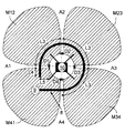
仏国特許出願第00 15715号との相違点として、本発明の改良例におけるビバルディ・アンテナを形成するスロットの下方端は、短絡回路で終端しない。アンテナ全体の中心は、メタライゼーションされず、スロット(A1、A2、A3、A4)を形成する種々の金属化プレート(M12、M23、M34、M41)を隔離し、各スロットを開回路で終端させることが可能である。スイッチングは、マイクロストリップラインと、ビバルディ型アンテナの励振スロットとの空の電磁カップリングを制御することによって実行される。このスイッチング原理は、単一スロットアンテナの場合と同じであり、ダイオード(D1、D2、D3、D4)若しくはその他のスイッチを、各アンテナを形成するマイクロストリップラインから約k’λs/4の距離でスロットを横切り、アンテナを形成する二つの金属表面を接続することができるように配置することによってスイッチングが行われる。ここで、k’は奇数である。受信ビバルディ・アンテナへの入力マイクロストリップラインと、送信ビバルディ・アンテナへの出力マイクロストリップラインとのスイッチングは、選択されたアンテナに対応したダイオードをオン状態にセットし、それ以外のダイオードをオフ状態に保つことによって制御される。ダイオード自体のスイッチングは、バイアス電位(V12、V23、V34、V41)を種々の金属表面(M12、M23、M34、M41)に夫々印加することにより実行される。二つの連続した表面のバイアスを変えることによって、この二つの表面を接続するダイオードは、オフ若しくはオン状態にさせられる。ここで記載した事項は、一般的に、nが1以上の整数を表わすとき、n個のスロットの場合に拡張することが可能であり、さらに、mがnよりも小さい整数を表わすとき、n本のアンテナのうちのm本のアンテナが作動状態を示すように選定することが可能である。
【0022】
図2には、簡単な4スロットの例が示されている。図2を参照して、ビバルディ・アンテナA1の受信中若しくは送信中の選択について説明する。ビバルディ・アンテナ1へ向かう入力/出力マイクロストリップライン8の間のスイッチングは、ダイオードD1をオン状態に設定し、ダイオードD2、D3及びD4をオフ状態で維持することによって制御される。これは、バイアス電圧を各金属表面に印加することによって行われ得る。このようにして、表面M12は電位V12に設定され、表面M23は電位V23に設定され、表面M34は電位V34に設定され、表面M41は電位V41に設定される。実際上、ダイオードD1がオン状態(すなわち、たとえば、V1がダイオードD1のバイアス電圧である場合に、V12−V41>V1であるとき)になるようなバイアス電位差(V12−V41)であるとき、ダイオードD1は、短絡回路と等価である。その他のダイオードに関しては、電位差は、ダイオードのバイアス電圧未満である。バイアス電位を制御する回路10を簡単化するため、電位Vcc>V1を表面M12に印加し、他の全ての表面を回路のアースに接続することだけが要求される。本発明の説明の際に記述したマイクロストリップライン8とスロットとの間のカップリングの原理を適用することにより、上述の条件下で、カップリングはアンテナA1において最大になり、他の3個のアンテナA2、A3及びA4において最小になる。このようにして、送信するために送信用として、受信するために受信用として、4個のアンテナの中から1個のアンテナが選択される。4個のアンテナからの1個の選択は、図3に関連して、スイッチングを実行するため種々の金属表面に印加される電位値を表わす以下の表とによって説明される。
【0023】
【表1】

【0024】
本発明の一改良例によれば、n個のアンテナの中からm個のアンテナをアクティブ状態にさせるため選択することが更に可能である(mはnよりも小さい整数である)。上記の例を簡単化するため、スロットの個数は4個であり、4個のスロットから2個のスロットを同時にアクティブ状態にするため選択する場合を考える。この場合、上述の組立体と同じ組立体において、4スロットの例に対して、3種類の電位を印加できるように制御回路を変更すればよい。3種類の電位は、金属表面を接地させることに対応した零電位と、ダイオードのバイアス電圧が異なる場合にダイオードのバイアス電圧の最大値よりも大きい電位Vccと、Vccの2倍に一致する電位である。以下の表では、図3に関して、4個のスロットから2個のスロットを選択する例が説明されている。この表には、望ましいスロットを選択するため種々のプレートに印加されるべき電位値が列挙されている。
【0025】
【表2】
【0026】
当業者に明らかであるように、上述の実施例は、請求項に記載された事項の範囲を逸脱することなく、特に、ビバルディ・アンテナの個数、或いは、この構造体に対する電源のタイプなどに関して変更できる。
【図面の簡単な説明】
【図1】スロットアンテナ用のスイッチング装置の説明図である。
【図2】スロットアンテナの円形配置用のスイッチング装置の説明図である。
【図3】制御手段を含むスロットアンテナの円形配置用のスイッチング装置の説明図である。
【符号の説明】
1,2 金属表面
3 基板
4 ダイオード
5 送受信手段
6 スロット
7,8 マイクロストリップ
9 外部手段
10 制御手段[0001]
BACKGROUND OF THE INVENTION
The present invention relates to a switching device for a device for transmitting and receiving signals, and more particularly to a switching device used in the field of wireless transmission.
[0002]
[Prior art]
In particular, in a conventional high-throughput wireless transmission system used in a home environment, the signal transmitted by the transmitter reaches the receiver along multiple separate paths. For this reason, interference that may cause fading and distortion in the transmission signal occurs on the receiver side, and as a result, information to be transmitted is lost or deteriorated. In order to overcome this drawback, horn type, reflection type or array type directional antennas are generally used. These antennas are used for transmission and reception, and are effective in deterioration related to multipath, or can reduce the deterioration. In particular, apart from the gain obtained by directional antennas, directional antennas, on the one hand, reduce the number of multipaths, on the one hand, by spatial filtering, and consequently reduce the amount of fading, and on the other hand the same frequency band. Interference with other systems operating in can be reduced.
[0003]
Since a directional antenna cannot widen spatial orientation coverage (receivable range), French Patent No. 00 15715 by the same applicant as the present application proposes a small assembling type antenna based on a Vivaldi antenna. Has been. This antenna includes a concentric arrangement of n Vivaldi antenna-type printed radiating elements (where n is a number greater than 2) and can provide several directional beams in time order. Depending on the set of beams, it is possible to cover the entire 360 ° range (omnidirectional) of the space.
[0004]
The switching operation is performed by a switch attached outside the antenna. In general, this switch consists of a diode combined with a power summing / distribution circuit and control electronics with at least n ports, and one or more Vivaldi antennas out of n elements. Can be selected. Often more than one diode is used on the port to ensure acceptable performance with respect to matching. In addition, the loss from the power summing / distribution circuit adds to the coupling loss of the slotline-microstripline change required to excite the Vivaldi antenna. Finally, the diode state (on or off) is controlled by the bias voltage. In order to be able to isolate the voltage applied to each port, a circuit that blocks DC current (DC blocking) is used. This causes further losses.
[0005]
[Problems to be solved by the invention]
Thus, the switching function is often expensive as a result of the price of the diode, the production cost, and the increased size for the biasing circuit and the power addition / distribution circuit. Furthermore, the switching function does not cause a slight power loss, but a loss in the distribution / summing circuit, a loss in DC blocking, and a loss in the diode. Due to these losses, the noise temperature of the receiver rises at the time of reception, a transmission power dry loss occurs at the time of transmission, and it is necessary to enlarge the power amplifier excessively, resulting in a significant cost increase.
[0006]
Therefore, an object of the present invention is to provide a switching device for a device that transmits and receives signals, which can reduce cost, overall size, and various losses.
[0007]
[Means for Solving the Problems]
The subject of the present invention is an apparatus for transmitting and receiving signals. This device
an assembly of n means for transmitting and receiving waves with slot antenna type longitudinal radiation, where n represents an integer greater than or equal to 1,
Excitation means electromagnetically connected to a slot of at least one antenna;
A switching device that operates by controlling electromagnetic coupling between the excitation means and at least one slot of the slot antenna;
A device comprising:
Switching device
At least one means for forming a reversible electrical contact between two metal surfaces defining one slot of the slot antenna (which includes a diode);
Means for controlling the state of the reversible electrical contact;
It is characterized by comprising.
[0008]
According to one embodiment, the excitation means comprises a microstrip power line. According to a variant, the excitation means are constituted by coplanar lines.
[0009]
According to another embodiment, the slot antenna includes at least one slot printed on the substrate, one end of the slot gradually extending toward the edge of the substrate, and the other end of the slot is similarly Not closed but extends to another edge of the substrate.
[0010]
According to another embodiment, the slot antennas are regularly arranged around a single coplanar point and therefore radiate in a 360 ° omnidirectional region.
[0011]
DETAILED DESCRIPTION OF THE INVENTION
Other features and advantages of the present invention will become apparent upon reading the following description of various embodiments with reference to the accompanying drawings.
[0012]
FIG. 1 is a schematic view of a Vivaldi antenna printed on a
λs = λ0 / √ε1reff
, And the case k 'is an odd number, at the operating frequency, approximately k'λs / 4 from microstrip Ppurain
Is the distance. Here, λ0 represents the wavelength in vacuum, and ε1reff represents the effective relative dielectric constant of the slot. For microstrip lines, approximately kλm / 4 from the slot
To an open circuit provided at a length L1 which is a distance of. here,
λm = λ0 / √εreff
And k is an odd number, λ0 represents the wavelength in vacuum, and εreff represents the effective relative dielectric constant of the line.
[0013]
The other end of the microstrip line is connected to a conventional signal transmission / reception means 5. The signal transmission / reception means 5 includes a power amplifier. For details on coupling, see: Knorr, “Slot-line transitions”, IEEE, MTT, Vol. 22, pp. 5480554, May 1974, and literature: Prasad and Mahapatra, “A Novel MIC Slot-Line Antenna. "checking. In order to produce coupling under the above-mentioned conditions shown in FIG. 1, the unextended end of the slot provided at a distance of k′λs / 4 from the microstrip line must be terminated in a short circuit. There is. If this end terminates in an open circuit, no coupling occurs between the microstrip line and the slot. The present invention is based on this coupling control.
[0014]
In order to simulate a short circuit or an open circuit, the end of the slot is not metallized, and the
[0015]
As described above, since the two biases applied to the metal surface are controlled, a switching device including a control circuit which is simple and is small and inexpensive since it is constituted by a single diode is provided.
[0016]
In one improvement of the present invention, a slot antenna is formed that realizes a continuous receivable space over 360 °.
[0017]
French Patent No. 00 15715 by the present applicant proposes a small antenna that can increase the spectral efficiency of the array by dividing the physical space to be included in the radiation pattern of the sector antenna and reusing the frequency. To do. The antenna proposed in this French patent 00 15715 is constituted by a coplanar circular arrangement around the center point of a Vivaldi-type printed radiating element that can show several directional beams in time sequence. . This set of beams covers the entire 360 ° of space.
[0018]
The transmission / reception means (reception and / or transmission means) is composed of all slots of the print slot antenna and microstrip lines or coplanar lines intersecting with these slots. The line distance L3 between the two slots corresponds to kλm / 2 at the central operating frequency of the system, and the line distance L4 between one end of the line and the slot corresponds to about λm / 4, where so,
λm = λ0 / √εreff,
λ0 is the wavelength in vacuum,
εreff is the effective relative dielectric constant of the line, and
k is an integer. Preferably, the length of the line between the two slots is matched to kλm so that the in-phase operation of the printed slot antenna can be realized.
[0019]
In this case, the slot and line intersection of the printed slot antenna is preferably formed at the central operating frequency of the system at a distance L5 of about k′λs / 4 from the lower end of the slot. here,
λs = λ0√ε1reff,
λ0 is the wavelength in vacuum,
ε1reff is the effective relative dielectric constant of the slot, and
k ′ is an odd number.
[0020]
The improvement proposed next is related to the switching system proposed in the previous patent application and extends the principle proposed in the present invention to several antennas. This refinement integrates this switching system directly with the antenna, thereby reducing the overall size and reducing the power loss associated with the switching function. The external system (5, 9) that can select the reception mode or transmission mode of the antenna directly performed on the microstrip line will not be described in detail. Only the switching means will be described in detail below.
[0021]
As a difference from the French patent application 00 15715, the lower end of the slot forming the Vivaldi antenna in the improvement of the invention is not terminated with a short circuit. The center of the entire antenna is not metallized, isolates the various metallization plates (M12, M23, M34, M41) forming the slots (A1, A2, A3, A4) and terminates each slot with an open circuit It is possible. Switching is performed by controlling the empty electromagnetic coupling between the microstrip line and the excitation slot of the Vivaldi antenna. This switching principle is the same as for a single slot antenna, with diodes (D1, D2, D3, D4) or other switches at a distance of about k'λs / 4 from the microstrip line forming each antenna. Switching takes place by placing the two metal surfaces that form the antenna across the slot so that they can be connected. Here, k ′ is an odd number. Switching between the input microstrip line to the receiving Vivaldi antenna and the output microstrip line to the transmitting Vivaldi antenna sets the diodes corresponding to the selected antenna to the on state and the other diodes to the off state. Controlled by keeping. Switching of the diode itself is performed by applying a bias potential (V12, V23, V34, V41) to the various metal surfaces (M12, M23, M34, M41), respectively. By changing the bias of two consecutive surfaces, the diode connecting the two surfaces is turned off or on. In general, the items described here can be extended to n slots when n represents an integer greater than or equal to n, and when m represents an integer smaller than n, n It is possible to select m antennas out of the three antennas to indicate the operating state.
[0022]
FIG. 2 shows a simple four-slot example. The selection during reception or transmission of the Vivaldi antenna A1 will be described with reference to FIG. Switching between the input / output microstrip line 8 towards the
[0023]
[Table 1]
[0024]
According to one refinement of the invention, it is further possible to select m antennas out of n antennas to activate (m is an integer smaller than n). In order to simplify the above example, consider the case where the number of slots is four and two slots are selected from the four slots to be simultaneously activated. In this case, the control circuit may be changed so that three kinds of potentials can be applied to the four-slot example in the same assembly as the above-described assembly. The three types of potentials are a zero potential corresponding to grounding the metal surface, a potential Vcc that is larger than the maximum value of the diode bias voltage when the diode bias voltage is different, and a potential that matches twice Vcc. is there. The following table describes an example of selecting two slots from four slots with respect to FIG. This table lists the potential values that should be applied to the various plates to select the desired slot.
[0025]
[Table 2]
[0026]
As will be apparent to those skilled in the art, the embodiments described above may be modified without departing from the scope of the claimed subject matter, particularly with respect to the number of Vivaldi antennas, or the type of power source for this structure, etc. it can.
[Brief description of the drawings]
FIG. 1 is an explanatory diagram of a switching device for a slot antenna.
FIG. 2 is an explanatory diagram of a switching device for circular arrangement of slot antennas.
FIG. 3 is an explanatory diagram of a switching device for circular arrangement of slot antennas including control means.
[Explanation of symbols]
1, 2
Claims (3)
少なくとも一つのアンテナのスロットに電磁気的に結合された電源ラインと、
該電源ラインとスロットアンテナの少なくとも一つのスロットとの間の電磁カップリングを制御することにより動作するスイッチング装置と、
を有する装置であって、
スイッチング装置は、
スロットアンテナの一つのスロットを画成する二つの金属表面間に可逆電気接点を形成する少なくとも一つの手段であって、
λ0が真空中の波長を表わし、
ε1reffがスロットの実効比誘電率を表わし、
k’が奇数を表わし、
λs=λ0/√(ε1reff)であるとき、
上記電源ラインから距離k’λs/4だけ離れている場所でスロットを横切るように設けられている手段と、
上記可逆電気接点の状態を制御する手段と、
を具備することを特徴とする装置。An assembly of one or more n printed slot antennas with longitudinal radiation;
A power line electromagnetically coupled to at least one antenna slot;
A switching device that operates by controlling electromagnetic coupling between the power line and at least one slot of the slot antenna;
A device comprising:
Switching device
At least one means for forming a reversible electrical contact between two metal surfaces defining one slot of the slot antenna,
λ0 represents the wavelength in vacuum,
ε1reff represents the effective relative dielectric constant of the slot,
k ′ represents an odd number,
When λs = λ0 / √ (ε1ref),
Means provided to traverse the slot at a distance k′λs / 4 from the power line;
Means for controlling the state of the reversible electrical contact;
The apparatus characterized by comprising.
スロットの第1の端は基板の一縁に向かって徐々に広がり、
閉じていないスロットの第2の端は基板の別の縁の方へ延びる、
ことを特徴とする請求項1記載の装置。The printed slot antenna includes at least one slot printed on a substrate,
The first end of the slot gradually widens toward one edge of the substrate,
The second end of the non-closed slot extends toward another edge of the substrate;
The apparatus according to claim 1.
λ0が真空中の波長を表わし、
ε1reffがスロットの実効比誘電率を表わし、
k’が奇数を表わし、
λs=λ0/√(ε1reff)であるとき、
スロットの上記第2の端からk’λs/4の距離だけ離れたシステムの中心動作周波数で交差することを特徴とする請求項2記載の装置。The slot of the printed slot antenna and the power line are
λ0 represents the wavelength in vacuum,
ε1reff represents the effective relative dielectric constant of the slot,
k ′ represents an odd number,
When λs = λ0 / √ (ε1ref),
3. An apparatus according to claim 2, characterized in that it intersects at the central operating frequency of the system at a distance of k '[lambda] s / 4 from said second end of the slot.
Applications Claiming Priority (2)
| Application Number | Priority Date | Filing Date | Title |
|---|---|---|---|
| FR0111399 | 2001-09-04 | ||
| FR0111399A FR2829298A1 (en) | 2001-09-04 | 2001-09-04 | SWITCHING DEVICE FOR ELECTROMAGNETIC WAVE RECEIVING AND / OR TRANSMITTING APPARATUS |
Publications (3)
| Publication Number | Publication Date |
|---|---|
| JP2003133848A JP2003133848A (en) | 2003-05-09 |
| JP2003133848A5 JP2003133848A5 (en) | 2005-10-27 |
| JP4209158B2 true JP4209158B2 (en) | 2009-01-14 |
Family
ID=8866928
Family Applications (1)
| Application Number | Title | Priority Date | Filing Date |
|---|---|---|---|
| JP2002256730A Expired - Fee Related JP4209158B2 (en) | 2001-09-04 | 2002-09-02 | Switching device for a device for transmitting and receiving electromagnetic waves |
Country Status (7)
| Country | Link |
|---|---|
| US (1) | US6847332B2 (en) |
| EP (1) | EP1291969A1 (en) |
| JP (1) | JP4209158B2 (en) |
| KR (1) | KR20030020824A (en) |
| CN (1) | CN1298112C (en) |
| FR (1) | FR2829298A1 (en) |
| MX (1) | MXPA02008448A (en) |
Families Citing this family (9)
| Publication number | Priority date | Publication date | Assignee | Title |
|---|---|---|---|---|
| FR2853996A1 (en) * | 2003-04-15 | 2004-10-22 | Thomson Licensing Sa | Antenna system for PCMCIA card, has transmission antenna placed between two reception antennas, where antenna system is placed at edge of PCMCIA card in zone placed exterior to PCMCIA card reader in computer |
| FR2904481A1 (en) * | 2006-07-31 | 2008-02-01 | Thomson Licensing Sas | Slot type antenna e.g. vivaldi type antenna, for e.g. set top box, has feeder electromagnetically coupled to slot according to knorr type coupling, and power combination circuit directly coupled to excitation point of antenna |
| US7397440B1 (en) * | 2006-11-27 | 2008-07-08 | The United States Of America As Represented By The Secretary Of The Navy | Extended phase center tapered slot antenna |
| WO2008139864A1 (en) * | 2007-05-16 | 2008-11-20 | Nec Corporation | Slot antenna |
| US7557765B2 (en) * | 2007-06-07 | 2009-07-07 | Asustek Computer Inc. | Smart antenna with adjustable radiation pattern |
| FR2925772A1 (en) * | 2007-12-21 | 2009-06-26 | Thomson Licensing Sas | RADIANT MULTI-SECTOR DEVICE HAVING AN OMNIDIRECTIONAL MODE |
| JP6039472B2 (en) * | 2013-03-15 | 2016-12-07 | 日東電工株式会社 | Antenna module and manufacturing method thereof |
| CN105206937A (en) * | 2015-08-31 | 2015-12-30 | 合肥工业大学 | Micro coaxial structure-based vivaldi ultra-wide band antenna |
| CN113922051B (en) * | 2021-11-03 | 2023-05-26 | 西安邮电大学 | Broadband MIMO antenna with self-decoupling characteristic |
Family Cites Families (4)
| Publication number | Priority date | Publication date | Assignee | Title |
|---|---|---|---|---|
| CA2147399A1 (en) * | 1994-06-01 | 1995-12-02 | Noach Amitay | Feed structure for use in a wireless communication system |
| CN2257964Y (en) * | 1996-05-03 | 1997-07-16 | 都世民 | Broadband plane microstrip antenna |
| US6285333B1 (en) * | 1999-05-20 | 2001-09-04 | Motorola, Inc. | Method and apparatus for changing the electrical characteristics of an antenna in a communications system |
| FR2817661A1 (en) | 2000-12-05 | 2002-06-07 | Thomson Multimedia Sa | DEVICE FOR RECEIVING AND / OR TRANSMITTING MULTI-BEAM SIGNALS |
-
2001
- 2001-09-04 FR FR0111399A patent/FR2829298A1/en active Pending
-
2002
- 2002-08-09 EP EP02292005A patent/EP1291969A1/en not_active Withdrawn
- 2002-08-27 KR KR1020020050815A patent/KR20030020824A/en not_active Application Discontinuation
- 2002-08-29 CN CNB02141971XA patent/CN1298112C/en not_active Expired - Fee Related
- 2002-08-29 MX MXPA02008448A patent/MXPA02008448A/en active IP Right Grant
- 2002-09-02 JP JP2002256730A patent/JP4209158B2/en not_active Expired - Fee Related
- 2002-09-03 US US10/233,792 patent/US6847332B2/en not_active Expired - Fee Related
Also Published As
| Publication number | Publication date |
|---|---|
| EP1291969A1 (en) | 2003-03-12 |
| MXPA02008448A (en) | 2005-08-26 |
| US6847332B2 (en) | 2005-01-25 |
| CN1298112C (en) | 2007-01-31 |
| US20030095073A1 (en) | 2003-05-22 |
| JP2003133848A (en) | 2003-05-09 |
| CN1407732A (en) | 2003-04-02 |
| FR2829298A1 (en) | 2003-03-07 |
| KR20030020824A (en) | 2003-03-10 |
Similar Documents
| Publication | Publication Date | Title |
|---|---|---|
| JP4021763B2 (en) | Device for receiving and / or transmitting multi-beam signals | |
| US7696948B2 (en) | Configurable directional antenna | |
| US6246377B1 (en) | Antenna comprising two separate wideband notch regions on one coplanar substrate | |
| JP4790192B2 (en) | Planar ultra-wideband antenna with integrated circuit | |
| US6292153B1 (en) | Antenna comprising two wideband notch regions on one coplanar substrate | |
| US7965242B2 (en) | Dual-band antenna | |
| CN102027638B (en) | Dual beam dual selectable polarization antenna | |
| JP2918602B2 (en) | Reversible hybrid mode circuit for coupling an RF transceiver to an RF radiator | |
| US7167136B2 (en) | Wideband omnidirectional radiating device | |
| EP1267446B1 (en) | Device for the reception and/or the transmission of electromagnetic signals with radiation diversity | |
| JP4209158B2 (en) | Switching device for a device for transmitting and receiving electromagnetic waves | |
| US20120326942A1 (en) | Sectorized Antenna | |
| US11456764B2 (en) | Multi-function communication device with millimeter-wave range operation | |
| US7292201B2 (en) | Directional antenna system with multi-use elements | |
| CN114498054A (en) | Directional diagram reconfigurable phase bit antenna and two-dimensional beam scanning array thereof | |
| JP4272154B2 (en) | Directional dual frequency antenna device | |
| US9941561B2 (en) | Systems and methods for high power RF channel selection | |
| JPH0786825A (en) | Directional diversity antenna | |
| CN112054311A (en) | Planar and low-profile quasi-yagi directional diagram reconfigurable 5G antenna | |
| US20180175506A1 (en) | Antenna Device | |
| Umar et al. | Antenna-Duplexed Passive Beamforming Front-end for Joint Communication and Sensing | |
| Marantis et al. | A pattern reconfigurable microstrip patch ESPAR designed for a hybrid beam-forming testbed | |
| Oh et al. | Beam-Steering Antenna with Tunable Beamwidth Using Rotman Lens and Power Combiner |
Legal Events
| Date | Code | Title | Description |
|---|---|---|---|
| A521 | Written amendment |
Free format text: JAPANESE INTERMEDIATE CODE: A523 Effective date: 20050826 |
|
| A621 | Written request for application examination |
Free format text: JAPANESE INTERMEDIATE CODE: A621 Effective date: 20050826 |
|
| A131 | Notification of reasons for refusal |
Free format text: JAPANESE INTERMEDIATE CODE: A131 Effective date: 20070717 |
|
| A601 | Written request for extension of time |
Free format text: JAPANESE INTERMEDIATE CODE: A601 Effective date: 20071015 |
|
| A602 | Written permission of extension of time |
Free format text: JAPANESE INTERMEDIATE CODE: A602 Effective date: 20071018 |
|
| A521 | Written amendment |
Free format text: JAPANESE INTERMEDIATE CODE: A523 Effective date: 20080116 |
|
| A131 | Notification of reasons for refusal |
Free format text: JAPANESE INTERMEDIATE CODE: A131 Effective date: 20080212 |
|
| A521 | Written amendment |
Free format text: JAPANESE INTERMEDIATE CODE: A523 Effective date: 20080509 |
|
| A131 | Notification of reasons for refusal |
Free format text: JAPANESE INTERMEDIATE CODE: A131 Effective date: 20080603 |
|
| A521 | Written amendment |
Free format text: JAPANESE INTERMEDIATE CODE: A523 Effective date: 20080829 |
|
| TRDD | Decision of grant or rejection written | ||
| A01 | Written decision to grant a patent or to grant a registration (utility model) |
Free format text: JAPANESE INTERMEDIATE CODE: A01 Effective date: 20080924 |
|
| A01 | Written decision to grant a patent or to grant a registration (utility model) |
Free format text: JAPANESE INTERMEDIATE CODE: A01 |
|
| A61 | First payment of annual fees (during grant procedure) |
Free format text: JAPANESE INTERMEDIATE CODE: A61 Effective date: 20081022 |
|
| R150 | Certificate of patent or registration of utility model |
Free format text: JAPANESE INTERMEDIATE CODE: R150 |
|
| FPAY | Renewal fee payment (event date is renewal date of database) |
Free format text: PAYMENT UNTIL: 20111031 Year of fee payment: 3 |
|
| LAPS | Cancellation because of no payment of annual fees |