JP4208450B2 - Face image monitoring system - Google Patents
Face image monitoring system Download PDFInfo
- Publication number
- JP4208450B2 JP4208450B2 JP2001316922A JP2001316922A JP4208450B2 JP 4208450 B2 JP4208450 B2 JP 4208450B2 JP 2001316922 A JP2001316922 A JP 2001316922A JP 2001316922 A JP2001316922 A JP 2001316922A JP 4208450 B2 JP4208450 B2 JP 4208450B2
- Authority
- JP
- Japan
- Prior art keywords
- image
- face
- person
- processing
- images
- Prior art date
- Legal status (The legal status is an assumption and is not a legal conclusion. Google has not performed a legal analysis and makes no representation as to the accuracy of the status listed.)
- Expired - Lifetime
Links
Images


Landscapes
- Image Processing (AREA)
- Closed-Circuit Television Systems (AREA)
- Image Analysis (AREA)
Description
【0001】
【発明の属する技術分野】
この発明は、画像処理装置であって、特にカメラ等からの画像情報を用いる顔画像監視システムに関するものである。
【0002】
【従来の技術】
最近、例えばコンビニエンスストア等の店舗においては、店内に設置されたITVカメラ等からの監視映像に基づく監視システムが非常に普及している。この監視システムには色々な形態があり、例えば以下の3種類が代表的に挙げられる。
一つは、店内に設置されたITVカメラが撮影した監視映像を監視センタに伝送し、監視員がモニタできるようにする監視システムがある。
【0003】
又、同様にITVカメラが撮影した監視映像を、タイムラプスVTRに一定間隔ごとに録画する監視システムがある。このシステムでは、監視員が常にモニタしている必要はなく、後に必要に応じて録画された画像を参照することができる。
更に、同様にITVカメラが撮影した監視映像から画像の変化に基づいて人物を検出し、VTRへの録画やディスクへの保存を行なう監視システムがある。このシステムでは、監視の対象となるべき画像変化があったときのみ画像を保存するので、少ない記憶容量でより効率的な監視画像の収集を行うことができる。
【0004】
【発明が解決しようとする課題】
しかしながら上記した各々の監視システムでは、以下のようにそれぞれ問題を有している。つまり、第1の監視システムでは、監視員が常時この監視画像をモニタしていなければならならず、人件費がシステムのコストとして非常に負担となるという問題がある。第2の監視システムでは、一定時間ごとに録画されるだけなので、人物のいない無意味な画像が多く記録されるため、記憶容量の不足や、必要画像の検索の困難性などが問題としてある。又更に第3の監視システムでは、人物のいる画像のみが得られるが、それが必ずしも後からの監視画像の確認に適切な画像だけではないという問題がある。
本発明は、ITVカメラ等からの撮影画像から監視に必要な画像だけを出力することで、より効率的な監視処理を実現する顔画像監視システムを提供することを目的とする。
【0005】
【課題を解決するための手段】
本発明は、監視対象の複数の画像情報を外部から連続的に受取る画像受取手段と、前記画像受取手段によって受取った画像情報から顔領域が検出されれば人物画像であると判断する人物画像判断手段と、前記人物画像判断手段が人物画像であると判断した前記顔領域について人物の顔の方向を検出し、この顔方向に基づき正面顔に近い画像に高い評価値を出力する顔方向評価手段と、前記複数の画像情報から前記顔方向評価手段により出力された評価値が高い所定数の前記画像情報を優先的に選択し出力する画像情報選択手段とを有することを特徴とする顔画像監視システムである。
本発明は上記した構成により、全ての顔画像を選択出力するのではなく、顔の方向を検出し、例えば人物判定により有効な正面の顔画像を中心に選択出力することで、顔画像監視に非常に有効な顔画像を自動検出することが可能となる。
【0006】
又本発明は、監視対象の複数の画像情報を外部から連続的に受取る画像受取手段と、前記画像受取手段によって受取った画像情報から顔領域が検出されれば人物画像であると判断する人物画像判断手段と、前記人物画像判断手段が人物画像であると判断した前記顔領域について顔の面積を検出し、この顔面積に基づき顔面積が大きい画像に高い評価値を出力する顔面積評価手段と、前記複数の画像情報から前記顔面積評価手段により出力された評価値が高い所定数の前記画像情報を優先的に選択し出力する画像情報選択手段と、を有することを特徴とする顔画像監視システムである。
本発明は上記した構成により、全ての顔画像を選択出力するのではなく、例えば顔面積が比較的大きい、顔画像監視に有効な画像のみを選択出力することにより、より効率的な顔監視処理を実現することができる。
【0016】
【発明の実施の形態】
この発明の各々の実施形態について、図面を参照して以下に詳細に説明する。
(第1実施形態)
まず初めに第1実施形態について、図面を用いて説明する。図1は、第1乃至第4実施形態の全体構成を示すブロックダイアグラムである。
【0017】
図1において、この顔画像監視システムの全体は、画像入力部1、A/D変換部2、画像バッファ(画像メモリ)3、画像処理部4(処理プロセッサ)からなる。
画像入力部1によって撮像された画像はA/D変換部2によってディジタル信号に変換され、画像メモリ3に格納される。処理プロセッサ4はその画像データを読み込んでディジタル画像処理を行なう。画像入力部1は例えば通常のCCDカメラであってよい。
【0018】
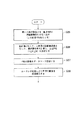
以下に、処理プロセッサ4での処理内容について詳細に説明する。図2は、第1実施形態の処理プロセッサ部の処理の流れを示すフローチャートである。
図2において、処理プロセッサ4で行なわれる処理の流れを示す。処理手順は、同一人物が存在するN枚の連続画像系列を切り出す処理(S5)と、選択画像枚数Pを決定する処理(S6)と、N枚の画像系列からP枚を選択する処理(S7)からなる。
【0019】
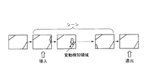
図3は、シーン抽出の様子を示す説明図であり、上記したN枚の連続画像系列の切り出し処理(S5)は、画像メモリ3から読み出された画像と、基準となる背景画像とを比較し、それらの違いから侵入した人物候補領域を検出し、人物が検出されている連続画像系列をシーンとして抽出するものである。
【0020】
人物領域検出は、例えば、連続する画像に対して差分処理を行ない、ノイズの影響を抑えるために平滑化処理を行なった後ある一定しきい値で2値化し、4連結または8連結の意味で空間的に連結する領域として統合・ラベリングを行ない、その領域の大きさ・形状から人物としての尤度の高いものを選択すればよい。このとき、2値化のしきい値は、あらかじめ与えた値であってもよいし、頻度分布の分散比を最大化する値とする手法[1]で決定してもよい。
【0021】
別手法として、事後確率にもとづく手法[2]を用いてもよい。事象θ0を背景、事象θ1を人物として、ある画像内の画素の輝度を観測する前のθ0,θ1の事前確率をそれぞれw0,w1(ただし、w0+w1=1)とし、事象θkのもとでの画像輝度Iの条件付き確率をP(I|θk)とすれば、ベイズの定理により、Iが観測された後の事後確率w1′は
w1′=w1* P(I|θ1)/{w0* P(I|θ0)+w1* P(I|θ0)}で求められる。このw1′があるしきい値よりも大きい画素を人物に属する画素とし、この領域がある一定のものを人物として検出すればよい。
【0022】
次に、同一人物が検出されている連続画像系列を一つのシーンとして切り出すための手順の一例を説明する。最初の画像(第1フレーム)の決定は、例えば監視画面の一方の端に初めて人物候補領域が検出された時(人物侵入時)とする。また、最後の画像(最終フレーム)の決定は、例えば監視画面の一方の端に人物候補領域が検出された後に人物候補領域が検出されなくなった時(人物退出時)とする。この結果、切り出された画像枚数をNとする。
【0023】
同一人物が含まれる連続画像の切り出しは、上記に限定されるものではなく、例えば、画面内検知位置によってあらかじめ定めておいたゾーンごとに分割して切り出してもよい。また、その位置・大きさ・移動速度・色情報の類似度などにより画像間で人物の対応づけを行ないながら追跡処理を行なうことにより、人物の動きとみなされない場合は、その人物候補領域を候補より除くなどの処理を行ない、人物判定の信頼性を高めることも可能である。
【0024】
また、人物は一人に限定されるものではなく、複数人物が含まれる場合でもこれらの追跡を行なうことにより各自が存在する連続画像をそれぞれ切り出すことが可能である(この場合、画像は重複して切り出される)。あるいは、複数人物が存在している連続画像を一まとまりとして切り出してもよい。
【0025】
最後に、選択画像枚数Pの決定方法を説明する。
ここでは、選択画像枚数Pを、選択率αをもとにP=[α* Nを越えない最大整数]とする。選択率αはあらかじめユーザが与えておいたものでもよいし、画像伝送部5:の混雑具合いにしたがって動的に変更してもよい。そして、N枚の中から均等に間引いてP枚を選択するものとする。
【0026】
以上の第1実施形態として示した手順により、従来のように移動物体が示された画像の全て(N枚)を選択出力するのではなく、これを一定の手法で選択することにより代表となるP枚を選択するものである。こうすることにより、画像の保存をする際にも非常に記憶容量の節約を行うことができ、更に後に照合検索等を行う場合も効率的な処理を行うことができる。
【0027】
(第2実施形態)
次に本発明の第2実施形態について図面を用いて説明する。本発明の実施形態の全体構成は、図1に示した第1実施形態と同じである。
以下に、処理プロセッサ4での処理内容について詳細に説明する。
【0028】
図4は、第2実施形態の処理プロセッサ部の処理の流れを示すフローチャートであり、処理プロセッサ4で行なわれる処理を示す。図4において処理手順は、N枚の連続画像系列をバッファリングする処理(S8)と、その連続画像系列の各画像に対して顔認識を行なって選択優先度を計算する処理(S9)と、その選択優先度に基づいて画像を選択する処理(S10)とからなる。
【0029】
処理S8は、単純に一定時間ごとにN枚をバッファリングしてもよいし、第1実施形態と同様に動き検知を行ない、人物が存在するN枚の連続画像を切り出してもよい。パラメータPの値は、あらかじめ固定値として与えておいてもよいし(PがN以上の時は、選択を行なわない)、第1実施形態のように選択率αをもとにP=[α* Nを越えない最大整数]としても良い。次に、与えられた連続画像系列の各画像に対して顔認識を行なって選択優先度を計算する方法について図5を用いて具体的に説明する。図5は、画像選択部における処理の具体例を示す説明図である。
【0030】
2−1.人物の顔方向評価値
例えば、人物の顔が正面向きで写っている画像は、より人物検証に適した画像であると考えられる。そこでユーザの求める顔方向(例えば正面顔)に近い画像に高い評価値を与え、優先的に選択する。
【0031】
人物の顔方向は、例えば正準判別分析[3]により求めることができる。これは、正面顔、左向き顔、右向き顔などのクラスに分類された学習用顔画像を用意して、以下のような正準判別分析による識別を行なうことで実現できる。
(a)A×Bドットの顔領域の画素値をA×B次元のベクトルと考え、クラス内分散Sb、クラス間分散Swを計算する。
(b)inv(Sw)Sb v=λvなる固有値問題を解く(inv(Sw)はSwの逆行列)。
(c)V=固有ベクトルviを列ベクトルとする射影行列を求める。
(d)各クラス画像の平均ベクトルをVに射影し、各クラスの平均射影ベクトルを計算する。
(e)認識時に入力画像領域をVに射影し、その結果を(d)における平均射影ベクトルと比較し、最も距離の近いクラスが入力画像の属するクラスだとするこの識別処理を、N枚の画像選択処理で検出された人物候補領域に対して行なうことで、顔の検知と顔方向の識別を行なうことができる。
【0032】
図6は、顔方向識別処理の概念を示す説明図であり、上記の説明を補うものである。
この手法の他に、目・鼻・口などの標準パターンを用意し、そのパターンと人物領域とのマッチングをとり、パターンの位置関係から顔の向きを認識してもよい。
【0033】
このようにして得られた顔方向に対して、ユーザが与えた評価値
{正面顔=100、左斜め顔=70、右斜め顔=70、
右顔=40、左顔=40、後ろ側=10、…}
を適用することで、人物の顔方向評価値E1が決定できる。
【0034】
2−2.人物の顔面積評価値
人物の顔が大きく写っている画像は、より人物検証に適した画像であると考えられる。そこで人物の顔面積が大きい画像に高い評価値を与え、優先的に選択する。顔領域の面積Sは、例えば連結した肌色領域の面積を求めることで得ることができる。よって、この値を人物の顔面積評価値とすればよい。
E2=S
2−3.人物の顔コントラスト評価値
顔のコントラストが高い画像は、より人物検証に適した画像であると考えられる。そこでこのコントラストが高い画像に高い評価値を与え、優先的に選択する。顔コントラストは、顔領域の輝度の分散値μをもとに計算できる。分散が大きいほど輝度の違いが大きくコントラストが高いといえるので、これを評価値とすればよい。よって、
E3=μ
とすることができる。
【0035】
2−4.人物の肌色鮮明度評価値
肌色の鮮明度が高い画像は、より人物検証に適した画像であると考えられる。そこでこの鮮明度が高い画像に評価値を与え、優先的に選択する。肌色鮮明度は、RGB画像をHSV(Hue,Saturation,Value)空間に変換する式[3]にもとづいて、顔領域の平均彩度(Saturation)をみることで評価することができる。
【0036】
例えば彩度Sは、
S=(I−i)/I
ただしI=max(R、G,B),i=min(R,G,B)
または
S={(B−R)2+(R−G)2+(G−B)2}/3
で求めることができる。よって肌色鮮明度評価値は、
E4=S
とすることができる。
【0037】
2−5.人物の顔表情評価値
顔の表情がニュートラル(目つぶりなどをしていない)な画像は、より人物検証に適した画像であると考えられる。そこでこの表情に優先度を与えて評価値を計算する。顔表情評価値は、例えば、普通の表情、目つぶり顔、口開き顔などのクラスに分類された学習用顔画像を用意して、前述した顔方向識別と同様の正準判別分析による識別を行ない、各クラスにユーザが与えた評価値
{普通の表情=100、目つぶり顔=70、口開き顔=60、…}
をもとにE5を決定すればよい。
また他の方法として、開いた目、閉じた目、開いた口、閉じた口などの標準パターンを用意し、そのパターンと顔領域とのマッチングをとり、パターンの組合せから表情を識別する方法で行なってもよい。
【0038】
実施形態は、上記に限定されるものではなく、シーン中に複数の人物が存在する場合は、例えば各人物に対する評価値を加算するなどすればよい。また、上記は、別々の独立した評価値としたが、これらを組み合わせて一つの評価値としてもよい。例えば、複数の評価値E1,E2,…,Ex(xは5以下)に対して重み付け係数w1,w2,…,wxをあらかじめ定義しておき、重み付け加算すればよい。
【0039】
E6=w1* E1+w2* E2+…+wx* Ex
また、評価尺度自身に優先順を定義し、E1で優先度順位をつけて同位の場合はE2で優先度順位をつけ、E2でも同位の場合はE3で優先度順位をつけていくという処理を行なってもよい。
【0040】
次に、その選択優先度に基づいて画像を選択する処理について説明する。ここでは、N枚の画像系列から、選択優先度の大きい順番にP枚の画像を選択する(PはN以下の整数で、適当にシステムより与えられるものとする)。選択された画像は、ネットワーク画像伝送したり、磁気ディスクやVTRなどの適当な画像記憶装置に保存する目的に使用することができ、選択された適切な画像のみを伝送・保存すればよいので伝送容量と保存容量が少なくて済む。
【0041】
処理形態については、ここではN枚からP枚を選択するとしているが、画像が1枚入力されるごとにその優先度Eiを計算し、優先度があるしきい値以上の時に選択画像とするような逐次処理であってもよい。
以上第2実施形態に示す方法で移動画像を選別し出力することで、様々な顔画像の諸条件に応じて、より効率的な顔画像の監視処理を実現することが可能となる。
【0042】
(第3実施形態)
次に本発明の第3実施形態について図面を用いて説明する。本発明の実施形態の全体構成は、図1で示した第1実施形態と同じである。
以下に、処理プロセッサ4での処理内容について詳細に説明する。
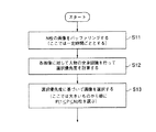
図7は、第3実施形態の処理プロセッサ部の処理の流れを示すフローチャートであり、処理プロセッサ4で行なわれる処理の流れを示す。処理手順は、N枚の連続画像系列をバッファリングする処理(S11)と、その連続画像系列の各画像に対して人物の全身認識を行なって選択優先度を計算する処理(S12)と、その選択優先度に基づいて画像を選択する処理(S13)とからなる。処理(S11)に関しては、第2実施形態と同様であってよい。
【0043】
次に、与えられた連続画像系列の各画像に対して人物の全体認識を行なって選択優先度を計算する方法(処理S12)について具体的に説明する。図8は、人物の計数、移動、全身性の認識処理を示す説明図であり、第3実施形態を説明するものである。
【0044】
3−1.人物の人数評価値
人物数が多い画像は、監視領域の様子をよりよくとらえているとして、これらを適切な画像として選択することが考えられる。逆に、人物数が少ないシーンは、監視領域での不正行為が行なわれている可能性が高いとして、これらを適切な画像として選択することも考えられる。よって、画像中の人物数にもとづいて優先度の評価値を求めることができる。最初に第1実施形態と同様な方法で人物領域を抽出し、それらの領域数から画面中に含まれている人物数Nhを求める。よって人数評価値は、
E7= Nh (人数が多いものを優先する場合)
または
E7=1/Nh(人数が少ないものを優先する場合)
とすることができる。
【0045】
3−2.人物の全身性評価値
人物の全体像をとらえている画像は、身長の高さ・服の色柄などが分かるため後からの人物検証に役立つので、このような画像に高い評価値を与え、優先的に選択する。最初に、第1実施形態と同様な方法で各画像ごとの人物領域の面積を計算する、次に、第2実施形態と同様な方法で顔領域面積を計算する。すなわち、人物領域の面積をS0、顔領域の面積をS1とすると、
E8=S0/S1
は全体像をどれだけとらえているかの評価値となる。例えば人物面積S0に対して顔面積S1が小さいということは、体部分までの全体像をよくとらえているということを意味し、その時S0/S1は大きな値をもつ。
【0046】
実施形態は、上記に限定されるものではなく、シーン中に複数の人物が存在する場合は、例えば各人物に対する評価値を加算するなどすればよい。また、上記は、別々の独立した評価値としたが、これらを組み合わせて一つの評価値としてもよい。例えば、複数の評価値E7,E8に対して重み付け係数w7,w8をあらかじめ定義しておき、重み付け加算すればよい。
【0047】
E9=w7* E7+w8* E8
また、評価尺度自身に優先順を定義し、E7で優先度順位をつけて同位の場合はE8で優先度順位をつけるという階層的な処理を行なってもよい。
【0048】
次に、その選択優先度に基づいて画像を選択する処理(S13)について説明する。ここでは、第2実施形態と同様に、N枚の画像系列から、選択優先度の大きい順番にP枚の画像を選択する(PはN以下の整数で、適当にシステムより与えられるものとする)。選択された画像は、ネットワーク画像伝送したり、磁気ディスクやVTRなどの適当な画像記憶装置に保存する目的に使用することができ、選択された適切な画像のみを伝送・保存すればよいので伝送容量と保存容量が少なくて済む。
【0049】
処理形態については、ここではN枚からP枚を選択するとしているが、画像が1枚入力されるごとにその優先度Eiを計算し、優先度があるしきい値以上の時に選択画像とするような逐次処理であってもよい。
第3実施形態においても、人物の人数、人物の全身性等の条件を設けることで、より効率的な人物の監視処理を実現することができる。
【0050】
(第4実施形態)
本発明の実施形態の全体構成は、図1に示す第1実施形態と同じである。
以下に、処理プロセッサ4での処理内容について詳細に説明する。図9は、第4実施形態の処理プロセッサ部の処理の流れを示すフローチャートであり、処理プロセッサ4で行なわれる処理の流れを示す。処理手順は、N枚の連続画像系列をバッファリングする処理(S14)と、与えられたN枚の連続画像系列のある画像Iiに対し、Ii自身と過去のk枚の画像の情報をもとに選択優先度を求める関数E(fi)=f(Ii−k,Ii−k+1,…,Ii)を定義し(Ii−kは、「i−k番目の画像I」を表す)、この関数にもとづいて選択優先度を計算する処理(S15)と、その選択優先度に基づいて画像を選択する処理(S16)とからなる。処理(S14)については、第2実施形態と同様でよい。
次に、関数にもとづいて、選択優先度を計算する処理(S15)について説明する。図8は、人物の計数、移動、全身性の認識処理を示す説明図である。
【0051】
4−1.人物の移動速度評価値
移動速度が小さいシーンは人物が安定して静止しており、より人物検証のしやすい適切な画像であると考えられる。よって、より移動速度が小さいシーンに高い評価値を与え、優先的に選択する。
【0052】
画像Ii−1とIiに含まれる人物領域の情報に対して、位置・大きさ・色の類似性などをもとに人物領域の対応関係を求め(人物追跡)、それらの位置の変化から移動ベクトル(移動速度)Vが求まる。よって人物の移動速度評価値は
E10=1/(c+V) (cは、V=0の時にゼロ除算を避けるための定数)
とすることができる。
【0053】
4−2.人物の非定常性評価値
人物が通常とは異なる動作を行なったシーンは、なんらかの特殊なイベントが発生している可能性が高く、検証において重要である。よってこれらの非定常性に対して高い評価値を与え、優先的に選択する。
【0054】
あらかじめ、定常的な動作・非定常的な動作に対する人物領域の特徴量(例えば移動ベクトル、位置、大きさ、形状)の変化系列の標準パターンを学習しておく。入力画像系列Ii−k,Ii−k+1,…,Iiに対しても同様に人物領域の特徴量の変化系列を求め、これらをDPマッチングやHMMモデルによるマッチングなどを行なって標準パターンとのマッチングを行なう。
【0055】
このときの定常的な動作としては、例えばコンビニエンスストア内での顔画像監視システムであれば、一般の客が立ち入るはずのないレジカウンタ内への侵入等が考えられる。画像内のレジカウンタ領域を設定しておくことで、移動物体がこの画像領域に侵入することを特殊イベントと判断する場合などである。
【0056】
ここで、入力画像系列に対して、定常動作の特徴量変化パターン群ではAmと最もマッチングスコアScore(Am)が高く、非定常動作の特徴量変化パターン群ではBnと最もマッチングスコアScore(Bn)が高かったとすれば、非定常性を表す評価値は
EE=(非定常との類似度)−(定常との類似度)=Score(Bn)−Score(Am)
で求めることができる。複数の特徴量系列に対する評価値EE1,EE2,…,EExを用いる場合は、重み付け係数ww1,ww2,…,wwxにより重み付け加算すればよい。
【0057】
E11=ww1* EE1+ww2* EE2+…+wwx* EEx
上記は、別々の独立した評価値としたが、これらを組み合わせて一つの評価値としてもよい。例えば、複数の評価値E10,E11に対して重み付け係数w10,w11をあらかじめ定義しておき、重み付け加算すればよい。
【0058】
E12=w10* E10+w11* E11
また、評価尺度自身に優先順を定義し、E10で優先度順位をつけて同位の場合はE11で優先度順位をつけるという階層的な処理を行なってもよい。
次に、その選択優先度に基づいて画像を選択する処理(S11)について説明する。ここでは、第2実施形態と同様に、N枚の画像系列から、選択優先度の大きい順番にP枚の画像を選択する(PはN以下の整数で、適当にシステムより与えられるものとする)。選択された画像は、ネットワーク画像伝送したり、磁気ディスクやVTRなどの適当な画像記憶装置に保存する目的に使用することができ、選択された適切な画像のみを伝送・保存すればよいので伝送容量と保存容量が少なくて済む。
【0059】
処理形態については、ここではN枚からP枚を選択するとしているが、画像が1枚入力されるごとにその優先度Eiを計算し、優先度があるしきい値以上の時に選択画像とするような逐次処理であってもよい。
第4実施形態においても、人物の移動速度や、所定領域内への侵入の検出等を参考にして画像を選別することで、より効率的な画像監視処理を実現することができる。
【0060】
(第5実施形態)
本発明の実施形態の全体構成は、図1に示された第1実施形態と同じである。
以下に、処理プロセッサ4での処理内容について詳細に説明する。
図10は、第5実施形態の処理プロセッサ部の処理の流れを示すフローチャートであり、処理プロセッサ4で行なわれる処理の流れを示す。処理手順は、N枚の連続画像系列をバッファリングする処理(S17)と、シーンに含まれる全画像N枚(I0からIN)からP枚を選ぶ「組み合せ」nCp通りに対して評価関数g( )を定義し、この関数にもとづいて選択優先度を計算する処理(S18)と、その選択優先度に基づいて画像を選択する処理(S19)とからなる。処理(S17)については、第2実施形態と同様でよい。
次に、関数に基づいて選択優先度を計算する処理14について図11を参照して説明する。図11は、P枚の組み合わせに基づく画像選択部における処理の具体例を示す説明図である。
【0061】
5−1.人物位置の多様性
ある人物が侵入してから退出するまでに移動した軌跡をできるだけ等間隔にサンプルする画像を選択すれば、それは人物の行動の全体をより適切に要約していると考えられる。よってこのような画像をP枚選択する。(画像枚数にもとづいた単純な等間隔サンプリングでは、立ち止まり状態ばかりが選択されてしまう場合がある)
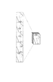
画像Iiにおける人物の座標(X(Ii),Y(Ii))は、N枚の画像系列の選択部8:において人物候補領域として求まっている。またIiからIjへの移動ベクトルは、Iiにおける座標とIjにおける座標の差として求められる。よって、N枚の画像からP枚を選び出した{I′i,…,I′P}の画像の組(nCp通り)に対して、移動ベクトルの平均Vaveと移動ベクトルの分散Vdispを求め、Vaveが最大、Vdispが最小となるようなP枚の組を選択すればよい。つまり、Vaveが大きいということは画像間での移動が大きくなるよう適切に選択されていることを示しており、またVdispが小さいということはより等間隔に近いサンプリングが行なえていることを示している。図12は、人物位置の多様性に基づく選択の例を示す図である。
【0062】
5−2.人物顔の多様性
ある人物がより様々な方向を向いた画像を選択すれば、それは人物の特徴をより多くとらえており、検証に役立つと考えられる。よってこのような画像をP枚選択する。まず顔の方向とその尤度は、前述した正準判別分析による顔方向識別によって求められる。この時にシーンに含まれる顔方向クラスの種類数をCとする。より多様な顔方向の画像を得るには、N枚からP枚選ぶ組み合せの中から、顔方向の分散の大きい組を選択すればよい。例えば、顔方向クラスに1,2,…,Cのクラス番号をつけ、P枚の画像のクラス番号値の分散が最大になるように選択する。(どのクラスもまんべんなく選択されると、クラス番号値の分散は大きくなる)またこのとき、各画像の顔尤度の高さを重み付けしてもよい。以上の処理により、より様々な方向を向いた顔画像を選択することができる。
【0063】
上記の第1実施形態から第5実施形態は、リアルタイムで行なってもよいし、いったん画像を蓄積しておいて、後でバッチ型で処理してもよい。
以上第5実施形態においても、人物位置の多様性や人物顔の多様性を考慮した画像が選択出力されることにより、効率的な監視処理を実現できるものである。
【0064】
(第6実施形態)
最後に本発明の実施形態の全体構成を図13に示す。
図13において、この顔画像監視システムは、画像入力部20と、A/D変換部21と、画像バッファ(画像メモリ)22と、画像処理部23(処理プロセッサ)と、画像蓄積部24とからなる。
【0065】
画像入力部20によって撮像された画像はA/D変換部21によってディジタル信号に変換され、画像メモリ22に格納される。処理プロセッサ23はその画像データを読み込んでディジタル画像処理を行なう。画像入力部20は例えば通常のCCDカメラであってよく、画像蓄積部24は通常の磁気ディスクであってよい。
【0066】
以下に、処理プロセッサ23での処理内容について詳細に説明する。
図14に、処理プロセッサ23で行なわれる処理の流を示す。処理手順は、同一人物が存在するN枚の連続画像系列を切り出す処理(S25)と、各画像に対して人物及び顔画像認識を行なってN枚の画像系列からP枚を選択する処理(S26)と、P枚の画像を画像蓄積部に登録する処理(S27)と、画像蓄積部から画像を検索表示する処理(S28)とからなる。
【0067】
同一人物が存在するN枚の連続画像系列を切り出す処理(S25)は、第1実施形態と同じである。また、各画像に対して人物及び顔画像認識を行なってN枚の画像系列からP枚を選択する処理(S26)は、第2乃至第5実施形態と同様である。P枚の画像を画像蓄積部に登録する処理に関しては、その画像が撮影されたカメラID、時刻などの画像に関する付属情報とともにデータベース登録を行なう。データベースのデータ構造に関する定義はあらかじめ、例えば、リレーショナルテーブル形式により行なっておくものとする。ここでは、画像を検索表示する方法を具体的に説明する。図15は、本発明に係る画像検索、照合の概念を示す説明図である。
【0068】
画像選択された画像をサムネイル表示(代表画像表示)することで、ユーザが容易に監視画像を検証することができる。さらに、ユーザが提示した顔写真(例えば指名手配犯)を、これらの画像と自動的に照合を行なって類似度の高い顔画像または画像系列を表示させることが可能である。また、ユーザが指定するのは画像ではなく画像系列であってもよい。
【0069】
人物の照合は、指定された人物の画像/画像系列とその他の人物の顔画像群をもとに、主成分分析や正準判別分析により、指定された人物と類似したパターンを検索する[4][5]。また検索には、色情報の類似度を用いたり、第4実施形態で示したような特徴量系列の類似度を用いたりしてもよい。これらにより、監視画像系列から、例えばある人物を検索したり、ある挙動(例えばレジへの侵入)のみを取り出したりといったことが可能になる。
【0070】
以上第6実施形態によって、顔画像監視システムに画像蓄積部を設けたことにより、所定条件に応じて選択出力された画像を自動的に順次格納することが可能となる。更にこれらの格納画像について、一定条件に応じた代表画像をサムネイル表示させることにより、より直感的な監視状況の把握を可能とするものである。
【0071】
なお、参考文献を以下に列記する。
[1]大津:“判別および最小二乗基準に基づく自動しきい値選定法”,信学論,Vol.J63-D, No.4, pp.349-356,1980.
[2]中井:“事後確率を用いた移動物体検出手法”,情処研報,94-CV-90, pp.1-8,1994.
[3]高木,下田:“画像解析ハンドブック”,東京大学出版会,1991.
[4] W Zhao, R.Chellappa他:“Discriminant Analysis of Principal Components for Face Recognition”,International Conference on Automatic Face & Gesture Recognition, Nara, Japan, April 1998.
[5]B.Moghaddam, A.Pentland他:“Beyond Eigenfaces: Probabilistic Matching for Face Recognition”,International Conference on Automatic Face & Gesture Recognition, Nara, Japan, April 1998.
【0072】
【発明の効果】
以上詳述したようにこの発明によれば、監視画像の顔の向きなどを認識することで、より監視画像として適切な画像のみを選択して出力することができる。
【図面の簡単な説明】
【図1】図1は、第1乃至第4実施形態の全体構成を示すブロックダイアグラム。
【図2】図2は、第1実施形態の処理プロセッサ部の処理の流れを示すフローチャート。
【図3】図3は、シーン抽出の様子を示す説明図。
【図4】図4は、第2実施形態の処理プロセッサ部の処理の流れを示すフローチャート。
【図5】図5は、画像選択部における処理の具体例を示す説明図。
【図6】図6は、顔方向識別処理の概念を示す説明図。
【図7】図7は、第3実施形態の処理プロセッサ部の処理の流れを示すフローチャート。
【図8】図8は、人物の計数、移動、全身性の認識処理を示す説明図。
【図9】図9は、第4実施形態の処理プロセッサ部の処理の流れを示すフローチャート。
【図10】図10は、第5実施形態の処理プロセッサ部の処理の流れを示すフローチャート。
【図11】図11は、P枚の組み合わせに基づく画像選択部における処理の具体例を示す説明図。
【図12】図12は、人物位置の多様性に基づく選択の例を示す図。
【図13】図13は、第6実施形態の全体構成を示すブロックダイアグラム。
【図14】図14は、第6実施形態の処理プロセッサ部の処理の流れを示すフローチャート。
【図15】図15は、本発明に係る画像検索、照合の概念を示す説明図。
【符号の説明】
1 … 画像入力部
2 … A/D変換部
3 … 画像メモリ
4 … 処理プロセッサ
24 … 画像蓄積部[0001]
BACKGROUND OF THE INVENTION
The present invention relates to an image processing apparatus, and more particularly to a face image monitoring system using image information from a camera or the like.
[0002]
[Prior art]
Recently, for example, in a store such as a convenience store, a monitoring system based on a monitoring image from an ITV camera or the like installed in the store is very popular. There are various forms of this monitoring system. For example, the following three types are representatively mentioned.
One is a monitoring system that transmits a monitoring image taken by an ITV camera installed in a store to a monitoring center so that a monitoring person can monitor it.
[0003]
Similarly, there is a monitoring system that records a monitoring video taken by an ITV camera in a time-lapse VTR at regular intervals. In this system, it is not necessary for the supervisor to constantly monitor, and the recorded images can be referred to later as needed.
Similarly, there is a monitoring system that detects a person based on a change in an image from a monitoring video imaged by an ITV camera and records it on a VTR or saves it on a disk. In this system, since an image is stored only when there is a change in an image to be monitored, more efficient monitoring image collection can be performed with a small storage capacity.
[0004]
[Problems to be solved by the invention]
However, each of the monitoring systems described above has problems as follows. In other words, in the first monitoring system, there is a problem that the monitoring staff must always monitor the monitoring image, and the labor cost becomes very high as the system cost. In the second monitoring system, since only video is recorded at regular intervals, many meaningless images without a person are recorded, so there are problems such as insufficient storage capacity and difficulty in searching for necessary images. Furthermore, in the third monitoring system, only an image with a person is obtained, but there is a problem that it is not always an image suitable for confirmation of the monitoring image later.
In the present invention, only images necessary for monitoring are taken from images taken from an ITV camera or the like.outputThus, an object is to provide a face image monitoring system that realizes more efficient monitoring processing.
[0005]
[Means for Solving the Problems]
The present invention relates to image receiving means for continuously receiving a plurality of pieces of image information to be monitored from the outside, and image information received by the image receiving means.If a face area is detected fromA person image determining unit that determines that the image is a person image, and the person image determining unit determines that the image is a person image;The direction of the person's face is detected for the face area, and the image is close to the front face based on the face direction.Face to output evaluation valuedirectionAn evaluation means;High evaluation value output from the plurality of image information by the face direction evaluation meansA predetermined number of the image informationPreferentiallyA face image monitoring system comprising image information selecting means for selecting and outputting.
The present invention has the above-described configuration.Instead of selecting and outputting all the face images, the face direction is detected, and for example, the face image that is very effective for face image monitoring is automatically output by selecting and outputting mainly the front face image that is effective by person determination. It becomes possible to detect.
[0006]
The present invention also provides image receiving means for continuously receiving a plurality of pieces of image information to be monitored from the outside, and image information received by the image receiving means.If a face area is detected fromA person image determining unit that determines that the image is a person image, and the person image determining unit determines that the image is a person image;The face area is detected for the face area, and the face area is detected.Based onHigh for images with large face areaFace to output evaluation valueareaAn evaluation means;The evaluation value output by the face area evaluation means from the plurality of image information is highA predetermined number of the image informationPreferentiallyAn image information selection means for selecting and outputting the face image monitoring system.
The present invention does not selectively output all face images by the above-described configuration,For example, more efficient face monitoring processing can be realized by selectively outputting only images having a relatively large face area and effective for face image monitoring.
[0016]
DETAILED DESCRIPTION OF THE INVENTION
Embodiments of the present invention will be described below in detail with reference to the drawings.
(First embodiment)
First, a first embodiment will be described with reference to the drawings. FIG. 1 is a block diagram showing the overall configuration of the first to fourth embodiments.
[0017]
In FIG. 1, the entire face image monitoring system includes an image input unit 1, an A /
The image captured by the image input unit 1 is converted into a digital signal by the A /
[0018]
Hereinafter, the processing contents in the
FIG. 2 shows the flow of processing performed by the
[0019]
FIG. 3 is an explanatory diagram showing scene extraction. In the above-described cut-out processing (S5) of the N consecutive image series, the image read from the
[0020]
For example, human area detection is performed by performing difference processing on successive images, binarizing with a certain threshold value after performing smoothing processing to suppress the influence of noise, and in the sense of 4-connected or 8-connected. Integration and labeling may be performed as spatially connected regions, and a region having a high likelihood as a person may be selected from the size and shape of the regions. At this time, the threshold value for binarization may be a value given in advance, or may be determined by the technique [1] that sets the value that maximizes the variance ratio of the frequency distribution.
[0021]
As another method, the method [2] based on the posterior probability may be used. With the event θ0 as the background and the event θ1 as the person, the prior probabilities of θ0 and θ1 before observing the luminance of the pixels in an image are w0 and w1 (where w0 + w1 = 1), respectively, and the event θk Assuming that the conditional probability of the image luminance I is P (I | θk), according to Bayes' theorem, the posterior probability w1 ′ after I is observed is
w1 ′ = w1 * P (I | θ1) / {w0 * P (I | θ0) + w1 * P (I | θ0)}. A pixel whose w1 ′ is larger than a certain threshold value is set as a pixel belonging to a person, and a certain pixel having this area may be detected as a person.
[0022]
Next, an example of a procedure for cutting out a continuous image series in which the same person is detected as one scene will be described. The first image (first frame) is determined when, for example, a person candidate area is detected for the first time at one end of the monitoring screen (when a person enters). The last image (final frame) is determined when, for example, the person candidate area is not detected after the person candidate area is detected at one end of the monitoring screen (when the person leaves). As a result, the number of cut out images is N.
[0023]
Cutting out continuous images including the same person is not limited to the above. For example, the images may be cut out by dividing each zone in advance according to the detection position in the screen. In addition, if the person's movement is not considered by performing tracking processing while associating people between images based on their position, size, moving speed, similarity of color information, etc., the person candidate area is selected as a candidate. It is also possible to increase the reliability of person determination by performing processing such as more removal.
[0024]
In addition, the number of persons is not limited to one person, and even when a plurality of persons are included, it is possible to cut out continuous images in which each person exists by tracking them (in this case, the images are duplicated). Cut out). Or you may cut out the continuous image in which several persons exist as a unit.
[0025]
Finally, a method for determining the number of selected images P will be described.
Here, the selected image number P is set to P = [maximum integer not exceeding α * N] based on the selection rate α. The selection rate α may be given in advance by the user, or may be dynamically changed according to the degree of congestion of the image transmission unit 5 :. Then, it is assumed that P sheets are selected by thinning evenly out of N sheets.
[0026]
According to the procedure shown as the first embodiment above, instead of selecting and outputting all (N) images showing moving objects as in the prior art, a representative method is used by selecting them by a certain method. P sheets are selected. By doing so, it is possible to save a great amount of memory even when saving an image, and it is possible to perform efficient processing when performing a collation search or the like later.
[0027]
(Second Embodiment)
Next, a second embodiment of the present invention will be described with reference to the drawings. The overall configuration of the embodiment of the present invention is the same as that of the first embodiment shown in FIG.
Hereinafter, the processing contents in the
[0028]
FIG. 4 is a flowchart showing a processing flow of the processing processor unit of the second embodiment, and shows processing performed by the
[0029]
In the process S8, N sheets may be simply buffered at regular time intervals, or motion detection may be performed in the same manner as in the first embodiment, and N consecutive images in which a person exists may be cut out. The value of the parameter P may be given as a fixed value in advance (the selection is not performed when P is greater than or equal to N), or P = [α based on the selectivity α as in the first embodiment. * Maximum integer not exceeding N]. Next, a method for performing face recognition on each image of a given continuous image series and calculating a selection priority will be specifically described with reference to FIG. FIG. 5 is an explanatory diagram illustrating a specific example of processing in the image selection unit.
[0030]
2-1. Human face direction evaluation value
For example, an image in which a person's face is seen in front is considered to be an image more suitable for person verification. Therefore, a high evaluation value is given to an image close to the face direction desired by the user (for example, the front face), and the image is preferentially selected.
[0031]
The face direction of a person can be obtained by canonical discriminant analysis [3], for example. This can be realized by preparing learning face images classified into classes such as front face, left face, right face, etc., and performing identification by canonical discriminant analysis as follows.
(A) The pixel value of the face area of A × B dots is considered as an A × B dimensional vector, and intra-class variance Sb and inter-class variance Sw are calculated.
(B) Solve the eigenvalue problem inv (Sw) Sb v = λv (inv (Sw) is the inverse matrix of Sw).
(C) A projection matrix having V = eigenvector vi as a column vector is obtained.
(D) The average vector of each class image is projected onto V, and the average projection vector of each class is calculated.
(E) At the time of recognition, the input image area is projected onto V, and the result is compared with the average projection vector in (d). By performing the process on the person candidate area detected by the image selection process, it is possible to detect the face and identify the face direction.
[0032]
FIG. 6 is an explanatory diagram showing the concept of face direction identification processing, and supplements the above description.
In addition to this method, a standard pattern such as eyes / nose / mouth may be prepared, the pattern may be matched with a person region, and the face orientation may be recognized from the pattern positional relationship.
[0033]
Evaluation value given by the user for the face direction obtained in this way
{Front face = 100, Left diagonal face = 70, Right diagonal face = 70,
Right face = 40, left face = 40, back side = 10, ...}
By applying, the face direction evaluation value E1 of the person can be determined.
[0034]
2-2. Human face area evaluation value
An image with a large person's face is considered to be an image more suitable for human verification. Therefore, a high evaluation value is given to an image having a large face area of a person, and the image is preferentially selected. The area S of the face region can be obtained, for example, by calculating the area of the connected skin color region. Therefore, this value may be used as the human face area evaluation value.
E2 = S
2-3. Human face contrast evaluation value
An image with high face contrast is considered to be an image more suitable for human verification. Therefore, a high evaluation value is given to the image with high contrast, and the image is preferentially selected. The face contrast can be calculated based on the variance value μ of the brightness of the face area. Since it can be said that the greater the variance, the greater the difference in luminance and the higher the contrast, this may be used as the evaluation value. Therefore,
E3 = μ
It can be.
[0035]
2-4. Human skin color clarity evaluation value
An image having a high flesh color clarity is considered to be an image more suitable for human verification. Therefore, an evaluation value is given to the image with high definition and is preferentially selected. The skin color sharpness can be evaluated by looking at the average saturation (saturation) of the face area based on the equation [3] for converting an RGB image into an HSV (Hue, Saturation, Value) space.
[0036]
For example, saturation S is
S = (I−i) / I
However, I = max (R, G, B), i = min (R, G, B)
Or
S = {(BR)2+ (RG)2+ (GB)2} / 3
Can be obtained. Therefore, the skin color clarity evaluation value is
E4 = S
It can be.
[0037]
2-5. Human facial expression evaluation value
An image with a neutral facial expression (without blinking) is considered to be an image more suitable for human verification. Therefore, the evaluation value is calculated by giving priority to the facial expression. For facial expression evaluation values, for example, learning face images classified into classes such as normal facial expressions, blinking faces, and open mouth faces are prepared, and identification by canonical discriminant analysis similar to the above-described face direction identification is performed. Evaluation value given by the user for each class
{Normal expression = 100, blinking face = 70, open mouth face = 60, ...}
E5 may be determined based on the above.
Another method is to prepare standard patterns such as open eyes, closed eyes, open mouths, closed mouths, etc., match the pattern with the face area, and identify facial expressions from the combination of patterns. You may do it.
[0038]
The embodiment is not limited to the above. When there are a plurality of persons in the scene, for example, an evaluation value for each person may be added. Moreover, although the said was set as the separate independent evaluation value, it is good also as one evaluation value combining these. For example, weighting coefficients w1, w2,..., Wx may be defined in advance for a plurality of evaluation values E1, E2,.
[0039]
E6 = w1 * E1 + w2 * E2 + ... + wx * Ex
In addition, a priority order is defined for the evaluation scale itself, a priority order is assigned at E1, and if it is a peer, a priority order is assigned at E2, and if E2 is also a peer, a priority order is assigned at E3. You may do it.
[0040]
Next, processing for selecting an image based on the selection priority will be described. Here, P images are selected from the N image series in descending order of selection priority (P is an integer equal to or less than N and is appropriately given by the system). The selected image can be used for the purpose of network image transmission or saving to an appropriate image storage device such as a magnetic disk or VTR, and only the appropriate selected image needs to be transmitted and stored. Less capacity and storage capacity.
[0041]
As for the processing form, it is assumed here that P sheets are selected from N sheets. However, each time one image is input, the priority Ei is calculated, and the selected image is selected when the priority is equal to or higher than a certain threshold value. Such sequential processing may be used.
As described above, by selecting and outputting the moving image by the method shown in the second embodiment, it is possible to realize more efficient face image monitoring processing according to various conditions of the face image.
[0042]
(Third embodiment)
Next, a third embodiment of the present invention will be described with reference to the drawings. The overall configuration of the embodiment of the present invention is the same as that of the first embodiment shown in FIG.
Hereinafter, the processing contents in the
FIG. 7 is a flowchart showing a processing flow of the processing processor unit of the third embodiment, and shows a processing flow performed by the
[0043]
Next, a method (processing S12) for calculating the selection priority by performing overall recognition of a person for each image in a given continuous image series will be described in detail. FIG. 8 is an explanatory diagram showing the process of counting, moving and recognizing a person, and explains the third embodiment.
[0044]
3-1. Number of people evaluated
It is conceivable that images having a large number of persons capture the state of the monitoring area better and select them as appropriate images. On the other hand, scenes with a small number of persons are likely to be fraudulent in the monitoring area, and it may be possible to select these as appropriate images. Therefore, the priority evaluation value can be obtained based on the number of persons in the image. First, person areas are extracted by the same method as in the first embodiment, and the number of persons Nh included in the screen is obtained from the number of areas. Therefore, the number of people evaluated is
E7 = Nh (when priority is given to a large number of people)
Or
E7 = 1 / Nh (when priority is given to those with a small number of people)
It can be.
[0045]
3-2. Human systemic evaluation value
An image that captures the entire image of a person is useful for later human verification because the height, color pattern of clothes, etc. are known. Therefore, a high evaluation value is given to such an image, and the image is preferentially selected. First, the area of the person area for each image is calculated by the same method as in the first embodiment, and then the face area is calculated by the same method as in the second embodiment. That is, if the area of the person area is S0 and the area of the face area is S1,
E8 = S0 / S1
Is an evaluation value of how much the whole image is captured. For example, the fact that the face area S1 is smaller than the person area S0 means that the whole image up to the body part is well captured, and then S0 / S1 has a large value.
[0046]
The embodiment is not limited to the above. When there are a plurality of persons in the scene, for example, an evaluation value for each person may be added. Moreover, although the said was set as the separate independent evaluation value, it is good also as one evaluation value combining these. For example, weighting coefficients w7 and w8 may be defined in advance for a plurality of evaluation values E7 and E8, and weighted addition may be performed.
[0047]
E9 = w7 * E7 + w8 * E8
Further, a hierarchical process may be performed in which a priority order is defined for the evaluation scale itself, and a priority order is assigned at E7 and a priority order is assigned at E8 in the case of peers.
[0048]
Next, the process (S13) for selecting an image based on the selection priority will be described. Here, as in the second embodiment, P images are selected from N image sequences in descending order of selection priority (P is an integer equal to or less than N, and is appropriately given by the system). ). The selected image can be used for the purpose of network image transmission or saving to an appropriate image storage device such as a magnetic disk or VTR, and only the appropriate selected image needs to be transmitted and stored. Less capacity and storage capacity.
[0049]
As for the processing form, it is assumed here that P sheets are selected from N sheets. However, each time one image is input, the priority Ei is calculated, and the selected image is selected when the priority is equal to or higher than a certain threshold value. Such sequential processing may be used.
Also in the third embodiment, more efficient person monitoring processing can be realized by providing conditions such as the number of persons and the generality of the person.
[0050]
(Fourth embodiment)
The overall configuration of the embodiment of the present invention is the same as that of the first embodiment shown in FIG.
Hereinafter, the processing contents in the
Next, the process (S15) for calculating the selection priority based on the function will be described. FIG. 8 is an explanatory view showing the process of counting, moving and recognizing a person.
[0051]
4-1. Human moving speed evaluation value
A scene with a low moving speed is considered to be an appropriate image in which the person is stable and stationary and is easier to verify the person. Therefore, a high evaluation value is given to a scene having a lower moving speed, and the scene is preferentially selected.
[0052]
Image Ii-1And IiIs obtained from the person area information contained in the image based on the similarity of position, size, color, etc. (person tracking), and the movement vector (movement speed) V is determined from the change in the position. Is obtained. Therefore, the moving speed evaluation value of the person is
E10 = 1 / (c + V) (c is a constant for avoiding division by zero when V = 0)
It can be.
[0053]
4-2. Person non-stationarity evaluation value
A scene in which a person performs an unusual operation is likely to have some special event, and is important in verification. Therefore, a high evaluation value is given to these non-stationarities and selected preferentially.
[0054]
In advance, a standard pattern of a change sequence of a feature amount (for example, a movement vector, a position, a size, and a shape) of a person region with respect to a steady motion / unsteady motion is learned in advance. Input image series Ii-k, Ii-k + 1, ..., IiSimilarly, a change sequence of the feature amount of the person region is obtained, and these are matched with a standard pattern by performing DP matching or matching with an HMM model.
[0055]
As a steady operation at this time, for example, in the case of a face image monitoring system in a convenience store, an intrusion into a cashier counter that a general customer cannot enter can be considered. For example, by setting a register counter area in an image, it is determined that a moving object enters the image area as a special event.
[0056]
Here, with respect to the input image series, the matching score Score (Am) is the highest in Am in the feature amount change pattern group of the steady motion, and the matching score Score (Bn) is highest in Bn in the feature amount change pattern group of the non-steady motion. Is high, the evaluation value indicating non-stationarity is
EE = (similarity with non-stationary state) − (similarity with stationary state) = Score (Bn) −Score (Am)
Can be obtained. When the evaluation values EE1, EE2,..., EEx for a plurality of feature quantity series are used, weighted addition may be performed using weighting coefficients ww1, ww2,.
[0057]
E11 = ww1 * EE1 + ww2 * EE2 + ... + wwx * EEx
The above is a separate independent evaluation value, but these may be combined into a single evaluation value. For example, weighting coefficients w10 and w11 may be defined in advance for a plurality of evaluation values E10 and E11, and weighted addition may be performed.
[0058]
E12 = w10 * E10 + w11 * E11
Further, a hierarchical process may be performed in which a priority order is defined for the evaluation scale itself, and a priority order is assigned at E10 and a priority order is assigned at E11 if the priority order is the same.
Next, the process (S11) for selecting an image based on the selection priority will be described. Here, as in the second embodiment, P images are selected from N image sequences in descending order of selection priority (P is an integer equal to or less than N, and is appropriately given by the system). ). The selected image can be used for the purpose of network image transmission or saving to an appropriate image storage device such as a magnetic disk or VTR, and only the appropriate selected image needs to be transmitted and stored. Less capacity and storage capacity.
[0059]
As for the processing form, it is assumed here that P sheets are selected from N sheets. However, each time one image is input, the priority Ei is calculated, and the selected image is selected when the priority is equal to or higher than a certain threshold value. Such sequential processing may be used.
Also in the fourth embodiment, more efficient image monitoring processing can be realized by selecting images with reference to the movement speed of a person, detection of intrusion into a predetermined area, and the like.
[0060]
(Fifth embodiment)
The overall configuration of the embodiment of the present invention is the same as that of the first embodiment shown in FIG.
Hereinafter, the processing contents in the
FIG. 10 is a flowchart showing a processing flow of the processing processor unit of the fifth embodiment, and shows a processing flow performed by the
Next, the process 14 for calculating the selection priority based on the function will be described with reference to FIG. FIG. 11 is an explanatory diagram illustrating a specific example of processing in the image selection unit based on a combination of P sheets.
[0061]
5-1. Diversity of person positions
If an image is selected that samples the trajectory that has moved from the intrusion to the exit of the person as equally as possible, it is thought that it better summarizes the entire behavior of the person. Therefore, P images are selected. (Simple equidistant sampling based on the number of images may select only the stationary state.)
Image IiThe coordinates of the person (X (Ii), Y (Ii)) Is obtained as a person candidate region in the selection unit 8: N image series. IiTo IjThe movement vector to is IiCoordinates and IjIs obtained as a difference in coordinates. Therefore, P images are selected from N images {I ′i, ..., I 'P} For a set of images (nCp ways)aveAnd movement vector variance VdispFor VaveIs the maximum, VdispIt is sufficient to select a set of P sheets that minimizes. That is, VaveA large value indicates that the movement between images is appropriately selected, and VdispA small value indicates that sampling at an equal interval can be performed. FIG. 12 is a diagram illustrating an example of selection based on diversity of person positions.
[0062]
5-2. Diversity of human faces
If a person selects an image that is directed in a variety of directions, it captures more of the person's characteristics and is considered useful for verification. Therefore, P images are selected. First, the face direction and its likelihood are obtained by face direction identification by the canonical discriminant analysis described above. At this time, the number of types of face direction classes included in the scene is C. In order to obtain images with more various face directions, it is only necessary to select a set having a large dispersion in the face direction from a combination of N to P. For example,
[0063]
The first to fifth embodiments described above may be performed in real time, or images may be accumulated once and processed later in a batch type.
As described above, also in the fifth embodiment, efficient monitoring processing can be realized by selecting and outputting an image in consideration of diversity of person positions and diversity of person faces.
[0064]
(Sixth embodiment)
Finally, the overall configuration of the embodiment of the present invention is shown in FIG.
In FIG. 13, the face image monitoring system includes an
[0065]
The image captured by the
[0066]
Hereinafter, the processing contents in the
FIG. 14 shows a flow of processing performed by the
[0067]
The process of cutting out N consecutive image sequences in which the same person is present (S25) is the same as in the first embodiment. Further, the process of performing person and face image recognition on each image and selecting P images from the N image sequences (S26) is the same as in the second to fifth embodiments. Regarding the process of registering P images in the image storage unit, database registration is performed together with attached information related to the image such as the camera ID and time when the image was taken. It is assumed that the definition relating to the data structure of the database is performed in advance in, for example, a relational table format. Here, a method for searching and displaying an image will be specifically described. FIG. 15 is an explanatory diagram showing the concept of image search and collation according to the present invention.
[0068]
By displaying the selected image as a thumbnail (representative image display), the user can easily verify the monitoring image. Furthermore, it is possible to automatically collate the face photograph (for example, a wanted person offender) presented by the user with these images and display a face image or image series having a high degree of similarity. The user may specify an image series instead of an image.
[0069]
In the matching of a person, a pattern similar to the designated person is searched by principal component analysis or canonical discriminant analysis based on the designated person image / image series and other person face image groups [4. ] [5]. In addition, the similarity of color information may be used for the search, or the similarity of the feature amount series as shown in the fourth embodiment may be used. Thus, for example, it is possible to search a certain person from the monitoring image series, or to extract only a certain behavior (for example, entry into a cash register).
[0070]
As described above, according to the sixth embodiment, by providing the face image monitoring system with the image storage unit, it is possible to automatically and sequentially store images selected and output in accordance with a predetermined condition. Furthermore, for these stored images, representative images corresponding to certain conditions are displayed as thumbnails, thereby enabling a more intuitive grasp of the monitoring status.
[0071]
References are listed below.
[1] Otsu: “Automatic threshold selection method based on discriminant and least square criterion”, IEICE, Vol.J63-D, No.4, pp.349-356, 1980.
[2] Nakai: “A moving object detection method using posterior probabilities”, Information Processing Research Bulletin, 94-CV-90, pp.1-8, 1994.
[3] Takagi, Shimoda: “Image Analysis Handbook”, The University of Tokyo Press, 1991.
[4] W Zhao, R. Chellappa et al. “Discriminant Analysis of Principal Components for Face Recognition”, International Conference on Automatic Face & Gesture Recognition, Nara, Japan, April 1998.
[5] B. Moghaddam, A. Pentland et al. “Beyond Eigenfaces: Probabilistic Matching for Face Recognition”, International Conference on Automatic Face & Gesture Recognition, Nara, Japan, April 1998.
[0072]
【The invention's effect】
As described above in detail, according to the present invention, the monitoring imageFace orientationBy selecting only the appropriate image as the monitoring imageoutputcan do.
[Brief description of the drawings]
FIG. 1 is a block diagram showing an overall configuration of first to fourth embodiments.
FIG. 2 is a flowchart illustrating a processing flow of a processing processor unit according to the first embodiment;
FIG. 3 is an explanatory diagram showing scene extraction.
FIG. 4 is a flowchart illustrating a processing flow of a processing processor unit according to the second embodiment;
FIG. 5 is an explanatory diagram showing a specific example of processing in an image selection unit.
FIG. 6 is an explanatory diagram showing a concept of face direction identification processing;
FIG. 7 is a flowchart illustrating a processing flow of a processing processor unit according to the third embodiment;
FIG. 8 is an explanatory view showing a process of counting, moving, and systemic recognition of a person.
FIG. 9 is a flowchart illustrating a processing flow of a processing processor unit according to the fourth embodiment;
FIG. 10 is a flowchart illustrating a processing flow of a processing processor unit according to the fifth embodiment;
FIG. 11 is an explanatory diagram illustrating a specific example of processing in an image selection unit based on a combination of P sheets.
FIG. 12 is a diagram illustrating an example of selection based on diversity of person positions.
FIG. 13 is a block diagram showing the overall configuration of a sixth embodiment.
FIG. 14 is a flowchart illustrating a processing flow of a processing processor unit according to the sixth embodiment;
FIG. 15 is an explanatory diagram showing the concept of image search and collation according to the present invention.
[Explanation of symbols]
1 ... Image input section
2 ... A / D converter
3 ... Image memory
4 ... Processing processor
24 ... Image storage unit
Claims (2)
前記画像受取手段によって受取った画像情報から顔領域が検出されれば人物画像であると判断する人物画像判断手段と、
前記人物画像判断手段が人物画像であると判断した前記顔領域について人物の顔の方向を検出し、この顔方向に基づき正面顔に近い画像に高い評価値を出力する顔方向評価手段と、
前記複数の画像情報から前記顔方向評価手段により出力された評価値が高い所定数の前記画像情報を優先的に選択し出力する画像情報選択手段と、を有することを特徴とする顔画像監視システム。Image receiving means for continuously receiving a plurality of pieces of image information to be monitored from outside;
A person image judging means for judging that the face area is detected from the image information received by the image receiving means;
A face direction evaluation unit that detects a face direction of a person for the face region that the person image determination unit has determined to be a person image, and outputs a high evaluation value to an image close to a front face based on the face direction;
A face image monitoring system comprising: image information selection means for preferentially selecting and outputting a predetermined number of the image information having a high evaluation value output by the face direction evaluation means from the plurality of image information. .
前記画像受取手段によって受取った画像情報から顔領域が検出されれば人物画像であると判断する人物画像判断手段と、
前記人物画像判断手段が人物画像であると判断した前記顔領域について顔の面積を検出し、この顔面積に基づき顔面積が大きい画像に高い評価値を出力する顔面積評価手段と、
前記複数の画像情報から前記顔面積評価手段により出力された評価値が高い所定数の前記画像情報を優先的に選択し出力する画像情報選択手段と、を有することを特徴とする顔画像監視システム。Image receiving means for continuously receiving a plurality of pieces of image information to be monitored from outside;
A person image judging means for judging that the face area is detected from the image information received by the image receiving means;
The person image determining unit detects the area of the face for the face area is determined that the portrait image, a face area evaluation means for outputting a high evaluation value in the face area is large image based on the face area,
A face image monitoring system comprising: image information selection means for preferentially selecting and outputting a predetermined number of the image information having a high evaluation value output by the face area evaluation means from the plurality of image information. .
Priority Applications (1)
| Application Number | Priority Date | Filing Date | Title |
|---|---|---|---|
| JP2001316922A JP4208450B2 (en) | 2001-10-15 | 2001-10-15 | Face image monitoring system |
Applications Claiming Priority (1)
| Application Number | Priority Date | Filing Date | Title |
|---|---|---|---|
| JP2001316922A JP4208450B2 (en) | 2001-10-15 | 2001-10-15 | Face image monitoring system |
Related Parent Applications (1)
| Application Number | Title | Priority Date | Filing Date |
|---|---|---|---|
| JP03105799A Division JP3727798B2 (en) | 1999-02-09 | 1999-02-09 | Image surveillance system |
Publications (3)
| Publication Number | Publication Date |
|---|---|
| JP2002191044A JP2002191044A (en) | 2002-07-05 |
| JP2002191044A5 JP2002191044A5 (en) | 2006-03-30 |
| JP4208450B2 true JP4208450B2 (en) | 2009-01-14 |
Family
ID=19134863
Family Applications (1)
| Application Number | Title | Priority Date | Filing Date |
|---|---|---|---|
| JP2001316922A Expired - Lifetime JP4208450B2 (en) | 2001-10-15 | 2001-10-15 | Face image monitoring system |
Country Status (1)
| Country | Link |
|---|---|
| JP (1) | JP4208450B2 (en) |
Cited By (1)
| Publication number | Priority date | Publication date | Assignee | Title |
|---|---|---|---|---|
| US9842409B2 (en) | 2012-07-19 | 2017-12-12 | Panasonic Intellectual Property Management Co., Ltd. | Image transmission device, image transmission method, image transmission program, image recognition and authentication system, and image reception device |
Families Citing this family (15)
| Publication number | Priority date | Publication date | Assignee | Title |
|---|---|---|---|---|
| JP2004151812A (en) * | 2002-10-29 | 2004-05-27 | Yokogawa Electric Corp | Face image processor |
| US20040207743A1 (en) | 2003-04-15 | 2004-10-21 | Nikon Corporation | Digital camera system |
| JP4325541B2 (en) | 2004-11-16 | 2009-09-02 | ソニー株式会社 | Image processing apparatus, reproduction image processing apparatus, image processing method, and reproduction image processing apparatus |
| JP2007028555A (en) | 2005-07-21 | 2007-02-01 | Sony Corp | Camera system, information processing device, information processing method, and computer program |
| JP2007047949A (en) * | 2005-08-08 | 2007-02-22 | Advanced Telecommunication Research Institute International | Apparatus for tracking mouse and computer program |
| JP4884096B2 (en) * | 2006-06-20 | 2012-02-22 | アルパイン株式会社 | Object identification system |
| JP5046148B2 (en) * | 2006-07-06 | 2012-10-10 | 株式会社メガチップス | Image analysis apparatus and object recognition method |
| JP4939968B2 (en) * | 2007-02-15 | 2012-05-30 | 株式会社日立製作所 | Surveillance image processing method, surveillance system, and surveillance image processing program |
| JP2009199232A (en) * | 2008-02-20 | 2009-09-03 | Seiko Epson Corp | Image processor |
| JP5239396B2 (en) * | 2008-02-28 | 2013-07-17 | セイコーエプソン株式会社 | Image output method, image output apparatus, and image output program |
| JP2010140425A (en) * | 2008-12-15 | 2010-06-24 | Hitachi Kokusai Electric Inc | Image processing system |
| KR101883258B1 (en) * | 2010-08-13 | 2018-07-31 | 스미스 앤드 네퓨, 인크. | Detection of anatomical landmarks |
| JP5374612B2 (en) * | 2012-05-18 | 2013-12-25 | キヤノン株式会社 | Image data identification method, imaging apparatus, program, and storage medium |
| JP5787845B2 (en) * | 2012-08-24 | 2015-09-30 | 株式会社東芝 | Image recognition apparatus, method, and program |
| JP6878842B2 (en) * | 2016-11-09 | 2021-06-02 | コニカミノルタ株式会社 | Image processor, authentication method and authentication program |
-
2001
- 2001-10-15 JP JP2001316922A patent/JP4208450B2/en not_active Expired - Lifetime
Cited By (1)
| Publication number | Priority date | Publication date | Assignee | Title |
|---|---|---|---|---|
| US9842409B2 (en) | 2012-07-19 | 2017-12-12 | Panasonic Intellectual Property Management Co., Ltd. | Image transmission device, image transmission method, image transmission program, image recognition and authentication system, and image reception device |
Also Published As
| Publication number | Publication date |
|---|---|
| JP2002191044A (en) | 2002-07-05 |
Similar Documents
| Publication | Publication Date | Title |
|---|---|---|
| JP3727798B2 (en) | Image surveillance system | |
| JP4208450B2 (en) | Face image monitoring system | |
| JP4021873B2 (en) | Face image monitoring system | |
| JP5390322B2 (en) | Image processing apparatus and image processing method | |
| US8866931B2 (en) | Apparatus and method for image recognition of facial areas in photographic images from a digital camera | |
| CN102902959B (en) | Face recognition method and system for storing identification photo based on second-generation identity card | |
| US8526742B2 (en) | Image processing apparatus, method, and program that classifies data of images | |
| Jesorsky et al. | Robust face detection using the hausdorff distance | |
| JP6013241B2 (en) | Person recognition apparatus and method | |
| US8351662B2 (en) | System and method for face verification using video sequence | |
| JP5649425B2 (en) | Video search device | |
| US8724845B2 (en) | Content determination program and content determination device | |
| JP5517858B2 (en) | Image processing apparatus, imaging apparatus, and image processing method | |
| US20150339516A1 (en) | Collation apparatus and method for the same, and image searching apparatus and method for the same | |
| US20120308090A1 (en) | Facial image search system and facial image search method | |
| JP2001216515A (en) | Method and device for detecting face of person | |
| WO2005008593A1 (en) | Image processing device, imaging device, image processing method | |
| WO2007105768A1 (en) | Face-image registration device, face-image registration method, face-image registration program, and recording medium | |
| Luo et al. | Human action detection via boosted local motion histograms | |
| US20150278585A1 (en) | Video processing system for video surveillance and methods for use therewith | |
| JP2000082147A (en) | Method for detecting human face and device therefor and observer tracking display | |
| KR100602576B1 (en) | Face recognition method, and method for searching and displaying character appearance using the same | |
| KR101344851B1 (en) | Device and Method for Processing Image | |
| Mohammed et al. | Face Recognition Based on Viola-Jones Face Detection Method and Principle Component Analysis (PCA) | |
| Singletary et al. | Symbiotic interfaces for wearable face recognition |
Legal Events
| Date | Code | Title | Description |
|---|---|---|---|
| A521 | Written amendment |
Free format text: JAPANESE INTERMEDIATE CODE: A523 Effective date: 20060209 |
|
| A621 | Written request for application examination |
Free format text: JAPANESE INTERMEDIATE CODE: A621 Effective date: 20060209 |
|
| A977 | Report on retrieval |
Free format text: JAPANESE INTERMEDIATE CODE: A971007 Effective date: 20080630 |
|
| A131 | Notification of reasons for refusal |
Free format text: JAPANESE INTERMEDIATE CODE: A131 Effective date: 20080708 |
|
| A521 | Written amendment |
Free format text: JAPANESE INTERMEDIATE CODE: A523 Effective date: 20080904 |
|
| TRDD | Decision of grant or rejection written | ||
| A01 | Written decision to grant a patent or to grant a registration (utility model) |
Free format text: JAPANESE INTERMEDIATE CODE: A01 Effective date: 20081014 |
|
| A01 | Written decision to grant a patent or to grant a registration (utility model) |
Free format text: JAPANESE INTERMEDIATE CODE: A01 |
|
| A61 | First payment of annual fees (during grant procedure) |
Free format text: JAPANESE INTERMEDIATE CODE: A61 Effective date: 20081021 |
|
| FPAY | Renewal fee payment (event date is renewal date of database) |
Free format text: PAYMENT UNTIL: 20111031 Year of fee payment: 3 |
|
| FPAY | Renewal fee payment (event date is renewal date of database) |
Free format text: PAYMENT UNTIL: 20111031 Year of fee payment: 3 |
|
| FPAY | Renewal fee payment (event date is renewal date of database) |
Free format text: PAYMENT UNTIL: 20121031 Year of fee payment: 4 |
|
| FPAY | Renewal fee payment (event date is renewal date of database) |
Free format text: PAYMENT UNTIL: 20131031 Year of fee payment: 5 |
|
| EXPY | Cancellation because of completion of term |