JP4208382B2 - Image processing method and image processing apparatus - Google Patents
Image processing method and image processing apparatus Download PDFInfo
- Publication number
- JP4208382B2 JP4208382B2 JP2000106377A JP2000106377A JP4208382B2 JP 4208382 B2 JP4208382 B2 JP 4208382B2 JP 2000106377 A JP2000106377 A JP 2000106377A JP 2000106377 A JP2000106377 A JP 2000106377A JP 4208382 B2 JP4208382 B2 JP 4208382B2
- Authority
- JP
- Japan
- Prior art keywords
- image
- division
- region
- coefficients
- watermark
- Prior art date
- Legal status (The legal status is an assumption and is not a legal conclusion. Google has not performed a legal analysis and makes no representation as to the accuracy of the status listed.)
- Expired - Fee Related
Links
Images


Classifications
-
- G—PHYSICS
- G06—COMPUTING; CALCULATING OR COUNTING
- G06T—IMAGE DATA PROCESSING OR GENERATION, IN GENERAL
- G06T1/00—General purpose image data processing
- G06T1/0021—Image watermarking
- G06T1/0028—Adaptive watermarking, e.g. Human Visual System [HVS]-based watermarking
-
- H—ELECTRICITY
- H04—ELECTRIC COMMUNICATION TECHNIQUE
- H04N—PICTORIAL COMMUNICATION, e.g. TELEVISION
- H04N1/00—Scanning, transmission or reproduction of documents or the like, e.g. facsimile transmission; Details thereof
- H04N1/32—Circuits or arrangements for control or supervision between transmitter and receiver or between image input and image output device, e.g. between a still-image camera and its memory or between a still-image camera and a printer device
- H04N1/32101—Display, printing, storage or transmission of additional information, e.g. ID code, date and time or title
- H04N1/32144—Display, printing, storage or transmission of additional information, e.g. ID code, date and time or title embedded in the image data, i.e. enclosed or integrated in the image, e.g. watermark, super-imposed logo or stamp
- H04N1/32149—Methods relating to embedding, encoding, decoding, detection or retrieval operations
- H04N1/32154—Transform domain methods
- H04N1/32165—Transform domain methods using cosine transforms
-
- H—ELECTRICITY
- H04—ELECTRIC COMMUNICATION TECHNIQUE
- H04N—PICTORIAL COMMUNICATION, e.g. TELEVISION
- H04N1/00—Scanning, transmission or reproduction of documents or the like, e.g. facsimile transmission; Details thereof
- H04N1/32—Circuits or arrangements for control or supervision between transmitter and receiver or between image input and image output device, e.g. between a still-image camera and its memory or between a still-image camera and a printer device
- H04N1/32101—Display, printing, storage or transmission of additional information, e.g. ID code, date and time or title
- H04N1/32144—Display, printing, storage or transmission of additional information, e.g. ID code, date and time or title embedded in the image data, i.e. enclosed or integrated in the image, e.g. watermark, super-imposed logo or stamp
- H04N1/32149—Methods relating to embedding, encoding, decoding, detection or retrieval operations
- H04N1/32154—Transform domain methods
- H04N1/3217—Transform domain methods using wavelet transforms
-
- H—ELECTRICITY
- H04—ELECTRIC COMMUNICATION TECHNIQUE
- H04N—PICTORIAL COMMUNICATION, e.g. TELEVISION
- H04N1/00—Scanning, transmission or reproduction of documents or the like, e.g. facsimile transmission; Details thereof
- H04N1/32—Circuits or arrangements for control or supervision between transmitter and receiver or between image input and image output device, e.g. between a still-image camera and its memory or between a still-image camera and a printer device
- H04N1/32101—Display, printing, storage or transmission of additional information, e.g. ID code, date and time or title
- H04N1/32144—Display, printing, storage or transmission of additional information, e.g. ID code, date and time or title embedded in the image data, i.e. enclosed or integrated in the image, e.g. watermark, super-imposed logo or stamp
- H04N1/32149—Methods relating to embedding, encoding, decoding, detection or retrieval operations
- H04N1/32154—Transform domain methods
- H04N1/32187—Transform domain methods with selective or adaptive application of the additional information, e.g. in selected frequency coefficients
- H04N1/32192—Transform domain methods with selective or adaptive application of the additional information, e.g. in selected frequency coefficients according to calculated or estimated visibility of the additional information in the image
-
- H—ELECTRICITY
- H04—ELECTRIC COMMUNICATION TECHNIQUE
- H04N—PICTORIAL COMMUNICATION, e.g. TELEVISION
- H04N1/00—Scanning, transmission or reproduction of documents or the like, e.g. facsimile transmission; Details thereof
- H04N1/32—Circuits or arrangements for control or supervision between transmitter and receiver or between image input and image output device, e.g. between a still-image camera and its memory or between a still-image camera and a printer device
- H04N1/32101—Display, printing, storage or transmission of additional information, e.g. ID code, date and time or title
- H04N1/32144—Display, printing, storage or transmission of additional information, e.g. ID code, date and time or title embedded in the image data, i.e. enclosed or integrated in the image, e.g. watermark, super-imposed logo or stamp
- H04N1/32149—Methods relating to embedding, encoding, decoding, detection or retrieval operations
- H04N1/32203—Spatial or amplitude domain methods
- H04N1/32229—Spatial or amplitude domain methods with selective or adaptive application of the additional information, e.g. in selected regions of the image
-
- G—PHYSICS
- G06—COMPUTING; CALCULATING OR COUNTING
- G06T—IMAGE DATA PROCESSING OR GENERATION, IN GENERAL
- G06T2201/00—General purpose image data processing
- G06T2201/005—Image watermarking
- G06T2201/0052—Embedding of the watermark in the frequency domain
-
- G—PHYSICS
- G06—COMPUTING; CALCULATING OR COUNTING
- G06T—IMAGE DATA PROCESSING OR GENERATION, IN GENERAL
- G06T2201/00—General purpose image data processing
- G06T2201/005—Image watermarking
- G06T2201/0065—Extraction of an embedded watermark; Reliable detection
-
- H—ELECTRICITY
- H04—ELECTRIC COMMUNICATION TECHNIQUE
- H04N—PICTORIAL COMMUNICATION, e.g. TELEVISION
- H04N2201/00—Indexing scheme relating to scanning, transmission or reproduction of documents or the like, and to details thereof
- H04N2201/32—Circuits or arrangements for control or supervision between transmitter and receiver or between image input and image output device, e.g. between a still-image camera and its memory or between a still-image camera and a printer device
- H04N2201/3201—Display, printing, storage or transmission of additional information, e.g. ID code, date and time or title
- H04N2201/3225—Display, printing, storage or transmission of additional information, e.g. ID code, date and time or title of data relating to an image, a page or a document
- H04N2201/3233—Display, printing, storage or transmission of additional information, e.g. ID code, date and time or title of data relating to an image, a page or a document of authentication information, e.g. digital signature, watermark
-
- H—ELECTRICITY
- H04—ELECTRIC COMMUNICATION TECHNIQUE
- H04N—PICTORIAL COMMUNICATION, e.g. TELEVISION
- H04N2201/00—Indexing scheme relating to scanning, transmission or reproduction of documents or the like, and to details thereof
- H04N2201/32—Circuits or arrangements for control or supervision between transmitter and receiver or between image input and image output device, e.g. between a still-image camera and its memory or between a still-image camera and a printer device
- H04N2201/3201—Display, printing, storage or transmission of additional information, e.g. ID code, date and time or title
- H04N2201/3269—Display, printing, storage or transmission of additional information, e.g. ID code, date and time or title of machine readable codes or marks, e.g. bar codes or glyphs
- H04N2201/327—Display, printing, storage or transmission of additional information, e.g. ID code, date and time or title of machine readable codes or marks, e.g. bar codes or glyphs which are undetectable to the naked eye, e.g. embedded codes
Description
【0001】
【発明の属する技術分野】
本発明は画像に透かし情報を挿入する技術に関する。
【0002】
【従来の技術】
デジタルデータに透かしを入れることは、例えばデータと著作権情報を関連付けることによって、これらのデータを保護することを可能にする。原則として、透かしを入れることは、追加情報をデータとして符号化することに例えられる消えない透かしをデジタルデータに挿入することから成る。この追加情報を復号することは、挿入されている著作権情報をチェックすることを可能にする。
【0003】
この挿入される透かしは、結果的に、デジタル画像に印加される特定の歪みに対して非感知的かつ堅固であり、しかも高い信頼度で検出可能でなくてはならない。従来、デジタル画像に透かし信号を挿入する通常の技法は、デジタル画像を表す係数の少なくとも1つの部分集合が、重み付け係数を使用したこの線形モデルに従って変調される線形変調モデルを使用することから成る。
【0004】
デジタル画像の少なくとも一部分を表す係数の集合をX={Xi,1≦i≦N}で表し、サイズP≦Nの透かしをw={wj,1≦j≦P}で表すことにより、分布が既知であって平均がゼロの疑似ランダム信号の線形の挿入式を次に示す:
X'j=Xj+bαjwj、但し、1≦j≦P
ここに、{Xj,1≦j≦P}は係数Xの集合の部分集合であり、bは1個の情報ビットであり、αjは変調振幅とも呼ばれる重み付け係数である。
【0005】
従って、透かしの検出は、疑似ランダム数列wが係数の集合内に挿入されているかどうかを検出することにある。この検出は、元の画像を用いずに実行され、正しい検出の確率算定を可能にする標準化された統計的テストに基づくことが可能である。ディテクタからの応答はバイナリ(イエス/ノー)であるので、この種の挿入技法は透かしの挿入により1つの単一情報を挿入することを可能にする。
【0006】
比較的多数の情報ビットをデジタル画像に挿入するためには、特に、例えば当該画像の所有者または著者の名前またはアドレスを表示するQビットのコード1つが必要とされる場合には、挿入されるべき情報ビットが存在する度毎に、既に述べた挿入方法を繰り返すことが必要である。一般に、2進信号を挿入するには、b1かb−1のいずれかが用いられる。
【0007】
他の方法において、Q個の係数部分集合を選定し、これらの部分集合の変調がQ個の透かしを選択することによって実行されなければならないものとする。係数の個別部分集合は、変調操作が相互に重なることのないように選定されることが好ましい。この場合、変調操作が相互に重なると、検出を妨害するか、或いは、面倒な視覚的効果を引き起こすことがあり得る。従って、前記の選択は、デジタル画像を表す係数をQ個の個別部分集合へ分割する方法を選定する問題を意味する。ここに、各部分集合が1つの情報ビットを担持する。
【0008】
【発明が解決しようとする課題】
既知の多数の方法は、スペクトル拡張によって所与のサイズの透かし信号を挿入する技法を使用する。これらの方法については、例えば、I.J.COXらによる「Secure spread spectrum watermarking for maultimedia」(議事録、ICIP、243−246頁、1996年9月)、F.HARTUNGらによる「Digital watermarking of raw and compressed video」(議事録、SPIE 2952)、「Digital Compression Technologies and Systems for Video Communication」(205−213頁、1996年10月)に記載済みである。これらの方法の欠点は、各々のブロックに実施される変調の検出可能性については一切保証なしに、画像を固定サイズのブロックへ随意に分割する技法が用いられることである。
【0009】
本発明の目的は、画像に挿入する透かし情報の検出可能性を保証することにある。
【0060】
【課題を解決するための手段】
本発明の画像処理方法は、分割手段が、画像を分割して分割領域を設定する分割ステップと、決定手段が、前記分割ステップで分割した前記分割領域の数により、前記画像の画像データに挿入される透かし情報により表現される情報の最大ビット数を決定する決定ステップと、を含み、前記分割ステップでは、透かし情報を前記分割領域毎に挿入した上で圧縮による歪みを印加したデータについて、挿入した各透かし情報の検出可能性が規定値以上となる範囲で、前記画像を4分木分割することを特徴とする。
【0063】
また、本発明の画像処理装置は、画像を分割して分割領域を設定する分割手段と、前記分割手段が分割した前記分割領域の数により、前記画像の画像データに挿入される透かし情報により表現される情報の最大ビット数を決定する決定手段と、を備え、前記分割手段は、透かし情報を前記分割領域毎に挿入した上で圧縮による歪みを印加したデータについて、挿入した各透かし情報の検出可能性が規定値以上となる範囲で、前記画像を4分木分割することを特徴とする。
【0096】
また、本発明によれば、上記画像処理方法をコンピュータに実行させるプログラムを記憶した記憶媒体が提供される。
【0097】
また、本発明の他の特殊性および利点は本発明に関する以下の記述からも明らかになるはずである。添付図面において、限定的意味をもつことのない例を示すこととする。
【0098】
【発明の実施の形態】
先ずデジタル画像Iを表す1組の係数への透かし挿入に関する図1を参照して説明する。
【0099】
このデジタル画像Iは、空間ドメイン或いは変換ドメインのどちらかにおける1組の係数で表すことができる。後者の場合における係数はハイブリッド係数、即ち、空間ドメインおよび周波数ドメインの両方に所在する係数である。この種の画像表現は、例えば離散型ウェーブレット分解のような画像の空間‐周波数分解から生じるサブバンドを用いて求められる。
【0100】
この場合、透かしの挿入は、デジタル画像Iの空間‐周波数変換によって得られる画像の空間‐周波数表現の係数の変調により、拡張スペクトル挿入技法を介して達成される。
【0101】
一例として、図2において図式的に表される離散型ウェーブレット分解Sを用いることができる。この空間‐周波数分解は、画像処理の分野ではよく知られているので、その原理だけを以下に復習する。前記分解は、画像を周波数のサブバンドに分割し、ハイブリッド係数、即ち、この場合の平面内である空間内に同様に位置するスペクトル係数を得ることを可能にする。
【0102】
画像Iは一連のデジタルサンプルから成る。画像Iは、例えば一連のバイトによって表され、各バイト値は、256個のグレーレベルをもつ黒白画像であっても差し支えない画像Iの1つの画素を表す。
【0103】
多重解像度スペクトル分解手段は、それぞれ2によるディバイダと関連する1組の分析フィルタによって形成されるサブバンド分解回路または分析回路から成る。この分解回路は、2つの方向における画像信号Iを、高空間周波数および低周波数のサブバンドに濾波する。回路は、幾つかの解像度レベルに従って画像Iをサブバンドへ分類する幾つかの連続した分析ブロックを含む。
【0104】
一例として、この場合、画像Iは、分解レベルdが3に等しいサブバンドに分類されるものとする。
【0105】
第1分析ブロックは、画像信号Iを受け取り、2つのそれぞれローパス及びハイパスデジタルフィルタを経て当該信号を第1方向、例えば水平方向に濾波する。2によるディバイダを経てパスした後で、結果として得られる濾波済み信号は、次に、2つのそれぞれローパス及びハイパスフィルタにより、第2方向、例えば垂直方向に濾波される。各信号は、再び、2によるディバイダを経てパスされる。従って、4つのサブバンドLL1、LH1、HL1、HH1が、分解における最高解像度をもってこの第1分析ブロックの出力で得られる。
【0106】
サブバンドLL1は、画像信号Iの2つの方向における低周波成分を含む。サブバンドLH1は、画像信号Iの第1方向に沿った低周波成分および第2方向に沿った高周波成分を含む。サブバンドHL1は、第1方向に沿った高周波成分および第2方向に沿った低周波成分を含む。最後に、サブバンドHH1は、2つの方向に沿った高周波成分を含む。
【0107】
次に、第2分析ブロックは、同じ方法で、分解における中間レベル解像度もつ4つのサブバンドLL2、LH2、HL2、HH2を供給するように低周波LL1のサブバンドを濾波する。次に第3分析ブロックは、4つのサブバンドLL3、LH3、HL3、HH3を供給するように低周波LL2のサブバンドを濾波する。この例においては、最後に、この分解における最低解像度をもつ4つのサブバンドLL4、LH4、HL4、HH4を供給するために、サブバンドLL3が第4分析ユニットによって分析される。
【0108】
従って、13のサブバンドと4つの解像度レベルが得られる。明らかなように、解像度レベルの個数、従ってサブバンドの個数は異なるように選択可能である。明らかなように、例えば離散型フーリエ変換、離散型コサイン変換、または、フーリエ−メリーン変換のような他のタイプのスペクトル変換も使用できる。
【0109】
一般的な方法において、その中に透かしを挿入可能な1組のスペクトル係数を形成することによって周波数サブバンドが得られる。ここでは、透かしを挿入するために、最高解像度HH1の高周波サブバンドを考察することができる。従って、このサブバンドHH1は、例えば、サイズがNに等しい1組の係数Xを供給する。
【0110】
デジタル画像Iを表す係数の集合をX={Xi,1≦i≦N}とする。明らかなように、デジタル画像Iの一部のみを表すこの集合Xの係数の部分集合を考察することが可能なはずである。
【0111】
この係数Xの集合に透かしを挿入するための一技法は、この疑似ランダム信号をスペクトル分析または統計的分析によって検出不可能にするように、そのスペクトルを拡大することによって、疑似ランダム信号を挿入することである。
【0112】
w={wj,1≦j≦P}を、サイズP≦Nの透かし、即ち、超関数が既知であって平均がゼロの疑似ランダム信号であるものとする。最も広範囲にわたる超関数は2進超関数{−1,1}、[−1,1]全域に渡る超関数、および、中心正規化ガウス超関数N(0,1)である。
【0113】
線形挿入式を次に示す。
【0114】
X'j=Xj+bσjwj、但し、1≦j≦P
ここに、{Xj、1≦j≦P}は係数Xの集合の部分集合であり、bは情報ビットであり、αjは、変調振幅振幅とも呼ばれる重み付け係数である。集合{j,1≦j≦P}も同様に情報ビット挿入キャリヤである。
【0115】
幾つかの情報ビットから形成可能な信号を挿入するために、領域の個数またはこの集合内の利用可能な挿入キャリヤの個数を決定するように係数の集合を分割することは価値あることである。それを実施するために、本発明にしたがった挿入デバイス10は分割11および挿入手段12を決定するデバイスを含む。
【0116】
分割11を決定するためのデバイスは、挿入された透かしの検出可能性の関数として、係数の集合の適応分割を実施するために適する。適応分割を実施するこの方法は、不可視性およびおよび適正検出確率に関してそれぞれ設定された判定基準を同時に満足させるように、当該透かしの情報ビットを挿入するために変調される係数の個数を変化させることにある。
【0117】
先ず、第図3を参照しながら、画像に挿入される情報ビットの個数を最大化するように求めた領域の個数を最大化することを可能にするデジタル画像の区分けされた領域への分割を決定する方法について説明することとする。
【0118】
空間領域または変換領域のどちらであっても、すなわち、空間領域および周波数領域の両方における係数の集合によるデジタル画像の表現について考察する。尤も、変換領域の場合には当該係数はハイブリッドである。この種の画像表現は、例えば、画像の空間と周波数分解から発散するサブバンドを用いることによって、既に述べた離散型ウェーブレット分解として求められる。
【0119】
画像の分割は各領域の係数の変調によって透かし信号を挿入するために実施される。本発明によれば、この領域への分割は、この領域へ挿入される情報ビットの検出可能性の判定基準の関数として適応分割することによって実施される。検出可能性の判定基準の拘束条件下において求められる領域の個数は、デジタル画像の最大容量を定義することを可能にする。この最大容量は、検出可能性の判定基準に適合するという条件付きでデジタル画像へ挿入可能な情報ビットの個数に対応する。
【0120】
初めに、ステップE100において、この容量Qは0に初期化され、開始点は、ここではサイズPの単一領域Rに制限される初期分割である。当然のことながら、初期分割は異なることが可能であり、サイズが異なる可能性のある幾つかの区分けされた領域を既に含んでいる。この初期領域RのサイズPは、係数の統計的に有意なサンプルの最小サイズに対応するPstatで表される最小サイズよりも大きいと仮定する。一般に、この最小のサイズは100に固定できる。この初期領域Rは、検討中の係数表現の集合、または、この表現の部分集合で構成可能である。
【0121】
次に、テストステップE101は、初期領域Rに挿入された透かし信号の検出可能性を検査する。この検出可能性検査は初期領域Rの係数に関する実際の変調および検出操作によって実施される。実際には、画像に直接透かししないように、初期領域Rの全ての係数がワーキングメモリにコピーされる。
【0122】
次に、初期領域Rの全ての係数が、透かし信号を挿入することによって変調される。この変調を実施するためには、従来と同様に、次の手順に従う:
初期領域が1つの係数集合から成る場合:
X:{Xi,i=1、...P}
通常、次に示すタイプの線形変調が用いられる:
Xi *=Xi±αiWi、但し、i=1,...,P
ここに、W:{Wi、i=1,...,P}は、既知分布と平均ゼロの疑似ランダム数列として選ばれた透かし信号である。
【0123】
変調の±符号値は、挿入されるべき2進値に依存する:例えば、―符号値は値0に対応し、+符号値は値1に対応する。一例として、インタバル[−1,1]をもつ均一則にに従う疑似ランダム数列を選定することが可能である。
【0124】
当然のことながら、既知分布と平均ゼロのあらゆる疑似ランダム透かし付けが適当であり得る。透かし信号Wとして最も一般的な分布は、前述の均一分布[−1,1]は別として、2進分布{−1,1}、及び、中心標準化ガウス分布N(0,1)である。変調は、例えば、疑似ランダム数列Wを再現するための核を特徴付けるシークレットキーによって随意に保護可能である。
【0125】
αi項は係数Xiへ適用された変調振幅または重み付け係数である。一定の重み付け係数は、領域Rの全ての係数に対して、例えば、あらゆるiに対してαi=αvのように使用可能である。この場合、重み付け係数αvの値は、前記デジタル画像を表す係数の集合の変調に対する透かし信号の非感知性を保証する最大値に等しい。
【0126】
この最大値αv(最小可知差異、または、JND振幅と称する)は、実際に、透かし信号Wの数列の長さと共に、従って、変調可能な係数の個数と共に減少する。デジタル画像表現の全ての係数が変調用に用いられる場合に容量Qが最大化されるものとすれば、画像を表す係数の集合数に等しい個数の変調可能な係数に関する変調JND振幅を決定することが賢明である。
【0127】
この最大の値αv、または、JND振幅は、これを超過すると復元された透かし入りの画像における変化を観察者が視覚的に検出可能であるような前述の線形挿入モデルにおいて使用可能な最大変調振幅に対応する。
【0128】
このJND振幅を決定するためには、異なるパラメータ、即ち、用いられる空間‐周波数変換Sを介する号の表現、挿入のために考察されるサブバンド、透かし信号数列Wの分布のタイプ、および、数列Wの長さPに基づいて透かし操作の可視性を予測することを可能にする可視性のモデルを使用することが可能である。
【0129】
WATSONによって開発され、「Visibility of wavelet quantization noise」(A.B.WATSON等著、IEEE Trans.on Image Process 6(8)、1164−1175、1997年)と題する論文に記載の単純モデルは、1つの単一被変調係数の測定値から変調済み係数の集合の可視性予測を可能にする。このモデルの詳細な記述に関してこの文書を有利に参照することができる。
【0130】
従って、透かし信号Wの長さP、使用する変換Sのタイプ、及び、挿入に関して考慮されるべき(基底)サブバンドに依存するが、透かしを入れるべき全ての係数Xから独立した関数を利用する。
【0131】
用いられるこの計算関数を次に示す:
【0132】
【数8】

βは2より厳密に大きく、E[|w|β]は、関数|w|βの数学的期待値である。
【0133】
基底値αbase(S)は、ウェーブレット分解における係数の各サブバンドに対して、1つの単一精神視覚測定から一度だけ全てに関して測定可能であり、視覚的振幅表内に記憶可能である。βはミンコフスキー和の累乗の指数であり、例えば5に選定可能である。数学的期待E[|w|β]は関数|w|βの平均推定に対応する。
【0134】
この可視性モデルは、それ自体に透かしが入れられる画像Iを考慮せず、従って、それから独立している。これは、画像Iが均一であると見なすことに等価である。これは、画像信号の存在がそれ自体の変調を視覚的にマスクすることを可能にするので、「最悪状態」モデルの問題である。
【0135】
従って、検討中のサブバンドの全ての変調可能係数の集合数に等しい透かし信号Wの長さPに関してJND振幅が算定可能である。ただし、画像信号自体が変調をマスクすることを可能にするという事実を利用することは賢明である。
【0136】
従って、この例において、変調されるべき各係数Xiに関して、式αi=ki.αvの法則に従った重み付け係数が用いられる。ここに、kiは領域R上で考察される係数の近くに位置する係数に依存する変調係数であり、αvは重み付け係数の最大JND値に等しい。
【0137】
従って、各係数は局所内容に従って変調され、検出可能性の利益が得られる程度まで変調振幅を局所的に増大することを可能にする。
【0138】
次に、検査ステップE101において検出可能性を検査するために、検出可能性の範囲が検出可能性の判定基準から算定され、検出可能性の範囲と、Tcで表される所定のしきい値とを比較することによって、この検出可能性の判定基準が検査される。
【0139】
全ての変調された係数X*とマーキング信号Wとの間の相関関係C(X*,W)が一般的に算定され、相関関係(X*,W)算定結果が所定のしきい値Tcより大きい場合に、画像の透かし入れが実際に実施されたかどうかが決定される。
【0140】
例えば、I.PITASによる「A method for signature casting on digital images」(議事録:ICIP、215−218頁、1996年9月)に記載されている標準化された統計的検査を検出のために使用できる。次に、検出は確率に関して特徴付けれれる。従って、固定した検出確率レベル、例えば99.95%に対応するしきい値Tcを選定することが可能である。
【0141】
従って、固定した重み付け係数αをもつサイズPの係数X集合を定義する所与領域Rに関して検出可能性の範囲を算定し、この領域R上の検出可能性の判定基準が妥当であるかどうかを検査するために算定結果としきい値Tcとを比較する。
【0142】
検出可能性の判定基準は、実際には、領域RのサイズP、必要とされる検出確率に関係する検出しきい値Tc、透かし信号W、領域Rにおいて変調されるべき係数Xの分散σ2xおよび、上述の線形モデルに基づいて係数Xを変調するために使用する重み付け係数αに依存する理論上の関数である。
【0143】
従って、例えば、標準化された仮説テスト及び領域Rの全ての係数Xiに関するαvに等しく、一定である値の重み付け係数αによる検出に関して、最小長さPmin(X)は、次の関数によって定義される。
【0144】
【数9】
【0145】
復号に際して、係数Xの集合は変調され、この関数も、挿入された透かしの分散σ2 wに依存する。
【0146】
更に、変調の後で画像に生じる可能性のある、例えば画像の圧縮に起因するあらゆる歪に対処することが必要である。
【0147】
このノイズが加法的であって係数と相関性がないと見なされる場合には、変調後の前記係数へ適応されるあらゆる歪みをモデル化するこの加法的ノイズの分散σ2 qに依存するモデルを使用することが可能である。
【0148】
従って、所与の重み付け係数αに対して、挿入される透かし信号、復号に際して必要な検出確率の関数として固定された検出しきい値Td、および、選定された係数Xの一集合の非可視性を保証することを可能にすることは、この場合にも挿入される透かし信号の検出可能性を保証することを可能にする最小変調長さPmin(X)に対応する。
【0149】
復号に際し、標準化された仮説検査による検出に関して、この最小長さPmin(X)は、次のように関数によって定義される
【0150】
【数10】
【0151】
従って、符号化と復号に際して同じ検出可能性検査が用いられる場合には、当該画像の復号に際して同じ分割を見付けることが出来るようにするために復号時に使用するTdより大きい符号化時のしきい値Tcを選定することが必要である。
【0152】
実際には、復号に際して用いようとするしきい値Tdは、例えば、検出が標準化された仮説検査によって行われる場合に必要とされる検出確率レベルに固定され、透かし信号Wにおける分散、および、画像が受ける後続処理の影響を予測するように演繹的に固定された加法的ノイズの分散を考慮するために、符号化に際して一層高いしきい値Tcが選定される。
【0153】
従って、この条件は、透かし信号Wの挿入時に実施される分割をデコーダに伝達することなしに、デジタル画像の分割を拘束する同じ検出可能性の判定基準を見付けることを可能にする。
【0154】
一例としてのこの実施形態においては、デジタル画像の反復的分割による分割が実施される。従って、ステップE101においては、算定された検出‐振幅が所定のしきい値Tc以上である場合に、検出可能性の判定基準が満足させられることが考察される。
【0155】
検出可能性の判定基準が満足させられない場合には、一般に検出確率は領域のサイズと共に減少するので、サイズが更に小さい初期領域Rの小領域(サブリージョン)においても検出可能性の判定基準が満足させられない可能性が大きいはずである。分割を決定する方法を停止するステップE102は、画像の反復的分割過程の停止を可能にする。
【0156】
初期領域Rにおける挿入が可能であると判断されない場合には、従って、画像の容量Qはゼロである。一方、検出可能性の判定基準が満足させられている、即ち、検出振幅がしきい値Tc以上である場合には、初期領域Rの小領域に対しても検出可能性の判定基準が満足させられていることが可能である。
【0157】
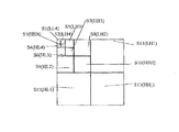
従って、検出可能性の判定基準が満足させられている限り、容量Qを増大するために領域Rの分割を試行することは賢明である。勿論、領域RのサイズPjの小領域Rjへの空間的分割を実施することが可能な幾つかの手段がある。ここに、j=1,...Kである。この例においては、図4に示すような、4分木が選定されている。この区分方法は各領域を同一サイズの4個の小領域に分割することから成る。
【0158】
従って、一例として図2に示すように、初期サイズNのデジタル画像は、サイズN/4の2個の小領域R5とR6、サイズN/16の7個の小領域R1、R2、R3、R4、R74、R8、R9、及び、サイズN/64の4個の小領域R10、R11、R12、R13に分割される。
【0159】
従って、区分ステップE103において、領域RはサイズPjの小領域Rj、j=1、...、Kに分割される。4分木に区分する場合には、K=4及びPj=P/4である。
【0160】
ステップE104において、指数j(例えばj=1)の第1小領域が考察され、GQで表される容量における潜在的利得の値は−1に初期化される。分割決定方法は、領域RjのサイズPjを、既に述べたように前記領域に挿入される透かし信号の検出に関して統計的に有意なサンプルの最小サイズに対応する最小サイズPstatと比較する前のステップE105を含む。
【0161】
ステップE108において領域RjのサイズPjがこの最小サイズPstat未満である場合には、後続小領域Rj+1を処理するために、指数J=J+1がインクレメントされる。
【0162】
そうでない場合には、ステップE101に関して既に述べた方法と同じ方法で、小領域Rjにおける検出可能性の判定基準がチェックされる。
【0163】
実際には、透かし信号は、前記領域Rjの係数に挿入され、検出振幅が算定され、この検出可能性の範囲がしきい値Tcと比較される。検出振幅は変調信号X*と透かし信号Wのキャリヤまたは標準化済み仮説検査の結果との間の相関値であり得る。検出可能性の判定基準が確認される場合には、容量GQにおける潜在利得の値は、ステップE107において、1単位だけ増大される。
【0164】
次に、ステップE108において、小領域の指数jがインクレメントされ、この指数jがKの数以下であることが、検査ステップE109においてチェックされる。肯定的である場合には、ステップE105からE109までが、その次の小領域上で繰り返される。
【0165】
そうでない場合には、指数j=K+1であれば、容量値GQにおける潜在利得が厳密に正であるかどうか、すなわち、それに関して検出可能性の判定基準が確認された初期領域Rの少なくとも2つの領域Rjが存在するかどうかが検査ステップE110においてチェックされる。
【0166】
否定的である場合には、初期領域R上で実施される更に高いランクの分割は確認されず、この領域Rは保存される。これは、任意の小領域Rjまたは1つの単一小領域Rjに関して検出可能性の判定基準が確認されなかった場合である。
【0167】
後者の場合、サイズPは確認された単一の小領域Rjのサイズより大きいので、透かし信号の挿入用として領域Rを保持することが好ましい。
【0168】
次に、ステップE112において、容量Qの値は1単位だけ増大され、分割におけるサイズPの領域Rが保持される。
【0169】
次に、領域Rの係数の変調による実際の挿入ステップE113は、既に述べた線形挿入モデルを用いる通常の仕方において、実行される。
【0170】
次に、除去ステップE114は、処理されるべき領域のスタックから領域Rを除去することを可能にする。
【0171】
一方、ステップE110において、潜在利得容量Gcの値が厳密に正である場合には、追加ステップE111において、それに関する検出可能性の判定基準が処理されるべき領域Rのスタック内で確認される全ての小領域Rjが追加される。
【0172】
戻りステップE115は、反復的様式においてスタックの領域を処理するために、ステップE103からE113までの全てのステップを繰り返すことを可能にする。
【0173】
上記の反復分割方法の終わりにおいて、透かし信号を挿入するための画像最大容量に対応する容量値Qmが求められ、この信号の正しい検出を保証する。この最大容量Qmは検出可能性の判定基準が確認された前記分割によって得られる区分けされた領域の集合数に等しい。
【0174】
更に、挿入ステップ自体E113は、第1「パス」に際して省略可能であり、これによって、画像の最大容量Qmおよび確認済み領域のみを決定することが可能になる。一旦、最大容量Qmが算定され、対応する分割がメモリに記憶されると、ユーザは、最大容量Qmに等しい情報ビット数に対応する挿入しようとするメッセージを決定し、以前に決定した分割によって得られた異なる領域の係数を変調することにより、通常の仕方において、このメッセージを挿入することが可能である。
【0175】
さて、図5を参照し、画像I内に固定容量Qsのメッセージを挿入しようとする本発明の第2実施形態について述べることとする。当然のことながら、この固定容量Qsは、透かしを入れようとするデジタル画像の最大容量Qm未満の値でなければならない。
【0176】
図5に示すように、この実施形態において分割を決定する方法はステップE100からE113までを含む。これらのステップは、図3の実施形態の分割を決定する方法のステップと同じであり、再びここで記述することは必要でない。以前の場合のように、隣接する高い方のランクの分割が確認されない場合には、ステップE112において、容量Qの値がインクレメントされる。
【0177】
次に、本方法は、容量Qのこの値が固定容量値Qsと比較される比較ステップE116を含む。実際には、ステップE116において、容量値Qが固定容量値Qsに等しいかどうかが検査される。
【0178】
肯定的である場合には、挿入しようとする情報ビットOs数に等しい数の領域が所在するので、停止ステップE117は、画像の反復的分割の停止を可能にする。そうでない場合には、除去ステップE114において、ステップE111において形成された処理されるべき領域Rのスタックから処理済み領域が除去される。
【0179】
この実施形態において、分割を決定する本方法は、これらの領域Rに関して算定された検出可能性の範囲値によって、スタックにおける処理されるべき領域Rを分類する分類ステップE118も含む。従って、戻りステップE115は、処理されるべき他の全ての領域の間の最高検出可能性の範囲を持つスタック内領域Rに関して、区分ステップE103から分割を繰り返す。
【0180】
演繹的に一層良好な検出可能性を備えた最大領域を優先的に処理するように、サイズが小さくなる順序に従って処理されるべき領域を分類することから成る分類用の変形種も可能である。当然のことながら、デジタル画像を反復的に結合することによる分割は、例えば、同様に、4分木分割構造を用いる同じ方法において、実施可能である。
【0181】
次に、初期分割は、以前に定義済みの最小サイズPstat以上であって、比較的小さい許容サイズの領域によって構成される。検出可能性の判定基準が確認されない分割を構成する各領域の場合、この領域は当該分割に属する他の領域と合併される。
【0182】
当該分割に属するこの別の領域は、可能であれば、容量を増大するようには検出可能性の判定基準が確認されない領域である。その代りに、さらに別の領域は、検出を信頼可能にするように検出可能性の判定基準を満足させる領域であり得る。
【0183】
結合されるべき領域の選択には多くの可能性がある。各領域について算定した検出振幅を結合判定基準として使用し、例えば最低検出振幅と関連した領域を結合することが可能である。
【0184】
4分木分割構造における結合に関するこの特定の場合において、結合することは構造的に拘束され、かつ4個の隣接ブロックであるかどうか、例えば図4におけるR1、R2、P3、R4が結合されなければならないかどうかを決定することによって構成される。
【0185】
図6を参照して、デジタル画像に挿入された透かし信号が抽出される場合に分割を見付けることを可能にする関連する復号方法について説明することとする。実際には、デジタル画像への分割適用であるので、この分割は、デコーダにおいて演繹的に既知ではない。
【0186】
従って、復号方法は、一般に、許容される全ての分割をテストすることによって構成される。透かしを挿入するための分割が決定された場合に使用されると同じ反復的実行技法が用いられる。
【0187】
従って、図3を参照して説明した実施形態の分割決定方法を用いる場合に対称な、4分木においてブロック別分割による区分の場合における一例としての実施形態について説明することとする。
【0188】
初期化ステップE200において、サイズPの単一領域Rに限定された初期分割が行われる。この領域は、透かし信号の挿入時に用いられる場合と同じデジタル画像の表現に含まれる全ての係数から成る。
【0189】
検査ステップE201は、以前に述べたように、初期領域RのサイズPが最小サイズPstatよりも実際に大きいことを検査することを可能にする。
【0190】
肯定的である場合には、ステップE203において、この領域Rにおける係数の復号によって得られ、領域Rへ挿入される情報ビットの検出可能性の判定基準が確認される。実際には、領域Rの全ての係数に関して検出振幅が算定され、この検出振幅と復号に関する所定のしきい値Tdとを比較することによって検出可能性の判定基準が確認される。標準化された統計的テスト、および、その結果の所定しきい値Tdとの比較により継続可能である。
【0191】
以前に説明したように、符号化と復号に際して同じ検出可能性テストが用いられる場合には、後処理によってノイズの多い複合が実施された場合であっても、画像の復元用に同じ配分を見付けようとする場合には、復号に用いられるTdより大きい符号化用しきい値Tcを選定することが必要である。
【0192】
従って、この条件は、透かし信号Wが挿入された時に実施された分割をデコーダへ伝達することなしにデジタル画像の分割を拘束する同じ検出可能性の判定基準を見付けることを可能にする。
【0193】
検出可能性の判定基準がステップE203において確認されない場合には、ステップE204において、領域RのサイズPjの小領域Rjへの分割が実施される。ここに、j=1,...、Kである。次に、符号化に際して、即ち、この例においては同じサイズの4個の小領域Rjへの領域Rの分割に際して用いられる分割構造と同じ分割構造が用いられる。
【0194】
次に、追加ステップE205において、処理されるべき領域Rのスタックに小領域Rjが加えられ、戻りステップE202において、復号方法が検査ステップE201からスタックの各領域Rに回帰的に繰り返される。
【0195】
検出可能性の判定基準E203を算定するステップにおいて、領域Rに関して、後者が確認された場合には、この領域Rに挿入された情報ビットが、抽出ステップE206において、デジタル画像Iに挿入された方法のエレメントとして、抽出される。この抽出は、検出振幅を算定することにより、従来の様式において実施される。テストの結果は、復号のしきい値Tdと比較されるべき検出振幅を絶対値で与える。この場合、符号は、挿入された情報ビットの値0または1を与える。
【0196】
この抽出は、検出ステップE203期間中に、既に部分的に実施されているので、検出ステップE203と抽出ステップE206とは構造的に結合していることに注意されたい。
【0197】
追加ステップE205において形成された処理されるべき領域のスタックから領域Rを除去するために、除去ステップE207が実行され、次に、戻りステップE202は、処理されるべきスタックの各領域Rに復号方法を反復的に実行することを可能にする。
【0198】
さて、図7及び8を参照して、本発明の特定実施形態におけるデジタル画像の分割を決定する方法の実用的な応用について説明することとする。この応用において、透かし信号は、図2に関して既に述べたように、デジタル画像Iの空間‐周波数変換Sによって得られる画像の空間‐周波数表現の係数を変調することによって、スペクトル拡張による挿入技法により挿入される。
【0199】
一般的な表現において、J=1,...、Mを用いてSjサブバンドが得られる。この場合には、変換ステップE300におけるMは13に等しい。
【0200】
次に、ステップE301において考察される指数jの各サブバンドSjに関して、図3に関して既に述べた分割を決定する方法を実行することにより、分割はステップE302において実施される。このように、容量Qjは各サブバンドSjに関して導出される。
【0201】
次に、係数の変調による挿入ステップE303は、Qj情報ビットの確認済みQj領域への挿入を可能にする。
【0202】
次に、ステップE304及び305において、全てのサブバンドSjが処理されていない限り、後続するサブバンドについて考察され、容量Qjの透かし信号を分割および挿入するステップE302およびE303が各サブバンドSjに繰り返される。
【0203】
次に、各サブバンドSjに関して算定した容量Qjの和に等しい全容量Qの透かし入りの画像を得るために、逆変換S−1を画像に適用する。
【0204】
従って、符号化および復号の両方において実施されるべき適応分割に関して、表現の各サブバンドが独立して考察される。
【0205】
図8に示すように、この実施形態における復号方法は、図6に関して記述した復号方法を用いて同様の様式において実行され、この場合、初期領域Rは毎回画像分解のサブバンドに対応する。
【0206】
ステップE300と同じステップE400は画像Iを、j=1,...,Mとした場合のSjサブバンドに分割する。
【0207】
第1サブバンドSjはステップE401において考察される。サブバンドの処理順序は順次挿入されたメッセージを抽出するための符号化に際して用いられる順序と同じである。
【0208】
適応分割は、サブバンドSjの容量Qjを算定するための分割ステップE402において実行される。次に、抽出ステップE403において、Qj情報ビットは、分割におけるQj領域の係数を復号することによって抽出される。
【0209】
検査ステップE404及びE405において、通常の仕方において、全てのサブバンドが処理済みであることがチェックされ、反対に、復号ステップE402及びE403(分割および抽出)が残りのサブバンドに繰り返される。
【0210】
このようにして、デコーダの出力において、Qビットのメッセージが得られる。ここに、Qは、各サブバンドSjの容量Qjの和に等しい。
【0211】
図9に示す方法の変形種において、画像が受けるあらゆる後処理に対する透かし信号の演繹的頑強性を得るために、後処理された画像信号に分割を実施することが可能である。
【0212】
この変形種の原理は、この段階においては、以前に述べた分割E302および挿入E303ステップには結合されていない検査ステップE309において検出可能性検査を実施することによって構成される。
【0213】
透かし信号を領域に挿入した後において、透かし入りの画像を見つけるために、まず第一に逆変換S−1がステップE306において実施される。次に、ステップE307において、例えばデジタル画像の圧縮のような後処理が適用される。
【0214】
次に、ステップE307において画像に後処理を実施することによってでき得ればノイズの多い状態に作成された透かし入り係数を見付けるために、ステップE308において変換Sが反復され、検出可能性の判定基準が以前に述べたように算定される。
【0215】
この場合には、例えば関連領域Rを4つに分割することによって、画像の別の許容分割に関してステップE300からE309までが繰り返され、ステップE309において、4つの小領域に関して検出可能性検査が実施される。
【0216】
この分割が容量における利得を表す場合にのみ、換言すれば、この4分木区分の例において、検出可能性の判定基準が少なくとも2つの小領域において確認された場合にのみ、この分割が採用される。この一変種実施形態は、デジタル画像へ適応される後処理を直接考慮することを可能にする。
【0217】
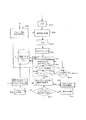
さて、図10を参照し、本発明の好ましい一実施形態に従って分割を決定する方法について説明することとする。デジタル画像Iに透かしを挿入する方法が採用されるものとする。本挿入方法は先ず第一にデジタル画像Iを表す係数の集合の分割を決定する方法を含む。
【0218】
この分割は挿入された情報ビットの検出可能性の判定基準の関数として分割の各領域へ適応される。実際には、透かしの挿入に関して、この画像の実際容量を確かめるように、最大数の検出可能性の判定基準を満足させる領域へのデジタル画像の分割を探索することが出来ることに注意されたい。デジタル画像のこの最大容量は、デジタル画像へ挿入可能な情報ビット数に対応し、同時に、検出可能性の判定基準に適合する。
【0219】
所与の透かしに関して、画像Iの最大容量未満の所与個数の情報ビットを含むことを条件に、可能な最大サイズの領域において挿入された透かしの不可視性を最も良く保証するように所与の検出確率に対して、所与の長さの透かしの挿入を可能にする画像Iの可能な最良の分割を探索することも可能である。
【0220】
分割を決定する方法は、先ず第一に、以前に述べた(離散型ウェーブレット変換またはDWT)ウェーブレット分解型のスペクトル分解ステップE500を含む。従って、デジタル画像Iを表すスペクトル係数Xが得られる。これらのスペクトル係数は、分解ステップE500の完成に際して、図2に略図的に示すように周波数サブバンドへ配分される。係数Xの集合のサイズは、方形画像に関してN=MxMに等しい。明らかなように、矩形画像に対しても同じ方法が適用できる。
【0221】
本発明のこの実施形態において、本方法は、画像Iを表す係数X集合の集合数Nに等しいサイズNの中心擬似ランダム数列を生成するステップE501を含む。この疑似ランダム数列をw={wmn,0≦m,n≦M}であるものとする。
【0222】
この疑似ランダム数列wは、中心擬似ランダムサブ数列wkから形成される。疑似ランダム数列は、疑似ランダムサブ数列wkの結合体と見なすことができる。この場合、中心擬似ランダム数列wは、単位ブロックと呼ばれる係数X集合のブロックに対応する同じサイズの疑似ランダムサブ数列wkから形成される。明らかなように、疑似ランダムサブ数列wkのサイズは相互に異なる。
【0223】
この場合、これら単位ブロックのサイズは、当該領域全体に渡り検出可能性の判定基準を満足させるために統計的に有意なサイズの領域形成に適した係数の最小数に対応する。後で述べるように、標準化済み統計的検出テストが係数集合に適用される場合には、このテストが有意であるためには最小数の係数が必要である。
【0224】
疑似ランダムサブ数列wkのサイズは係数のこの最小数以上のA=LxLである。この最小サイズに等しいサイズの疑似ランダムサブ数列wkが選定されることが好ましい。画像の初期区分からのブロックをサイズLxLの単位ブロックに組み合わせることによる反復組合わせによって分割が達成される場合に、この特性は特に有利である。従って、初期区分は、適用可能な画像の最大分割に対応する。この最大分割を越えると、生成される係数のブロックは、情報ビットの挿入および検出に関して、もはや統計的に有意ではない。例えば、L=8が選定されるものとする。この場合、疑似ランダム数列wは、単位ブロックを形成するN/64個の疑似ランダムサブ数列wkの結合体である。
【0225】
本発明に従えば、各単位ブロックに関して、シークレットキーKおよび各単位ブロックのインデックスkに依存する関数に基づいて事前定義済み分布(ガウス分布、均一分布、等々)の中心擬似ランダム信号が生成されなければならない。このキーはf(K、k)で表示可能である。次に、実際には、各単位ブロック全体に渡る信号wkの平均が厳密にゼロに等しいことを保証することが必要である。
【0226】
この種の中心擬似ランダム数列を生成する第1の方法は、対称化による決定論的方法により数列に中心を与えることによって構成される。この方法は、偶数サイズAの疑似ランダム数列の生成に適する。
【0227】
この場合、各々の中心擬似ランダムサブ数列wkは、既知の有中心分布疑似ランダム数ゼネレータを介して、サブ数列の疑似ランダムサンプルの半分A/2を生成し、疑似ランダムサブ数列wkのサンプルのもう一方の半分A/2を求めるために、このようにして生成された疑似ランダムサンプルを対称化することによって作成される。
【0228】
従って、単一次元数列の場合には、サイズA/2{wj,1≦j≦A/2)のサンプルの一集合が生成され、この集合は、サンプルのもう一方の半分{wj=−wA−j,A/2<j≦A)を求めるために対称化される。
【0229】
このようにして得られた数列のランダム特性を強化するために、シークレットキーを使うことよって得られたサンプル集合{wj,1≦j≦A)に置き換えを実施することができる。
【0230】
中心擬似ランダム数列を生成する第2の方法は、疑似ランダム数ゼネレータを介して疑似ランダムサンプルを生成し、各サンプル全体に亙って生成されたこれらの疑似ランダムサンプルの和を再配分することによって各々の中心擬似ランダムサブ数列wkを作ることによって構成される。
【0231】
従って、まず第一に、シークレットキーf(K、k)を使用することにより、単位ブロックと同じサイズAの一連の疑似ランダムサンプル、即ち{wj,1≦i≦A)が生成される。次に、これらサンプルの厳密な和が算定される:
【0232】
【数11】
【0233】
従って、疑似ランダム数列wは、中心擬似ランダム数列wによって変調された係数の分割が、同様に中心擬似サンダムサブ数列によって変調された係数の部分集合を生じるような方法における、中心を持つサブ数列wkの結合によって構成される。明らかなように、中心を持つランダム数列を生成するために他の技法を使用することができる。
【0234】
次に、図10に示すように、スペクトル分解から生成される係数集合に情報ビットを挿入するために、中心擬似ランダム数列wにより係数集合を変調するステップE502が実行される。実際には、画像Iに直接マークしないように、係数集合は、例えばコンピュータのランダムアクセスメモリのようなワーキングメモリにコピーされる。
【0235】
同じ情報ビットは、次に示す変調論式に基づいて、例えばこの場合にはb=1である係数集合に変調される。
【0236】
X'i=Xi+αiwi、但し、0≦i≦N。
【0237】
重み付け振幅αiは、挿入される情報ビットの不可視性を保証するような通常の方法で選定される。
【0238】
全ての係数に対して、例えば全てのαiに対してαi=αvのような、一定の重み付け係数を使用できる。この場合、重み付け係数αvの値は、デジタル画像を表す係数集合を変調する透かしの非感知性を保証する最大値に等しい。
【0239】
画像信号自体が変調をマスクすることを可能にするという事実を利用することは有益であり得る。
【0240】
そのためには、変調されるべき各係数Xiに関して、式αi=kiαvの法則に従って重み付け係数を使用することが可能である。ここに、kiは、問題の係数の近傍に位置する係数に依存する変調係数であり、αvは、当該係数集合の変調用透かしの非感知性を保証する重み付け係数の最大値に等しい。従って、各係数は、画像の局所内容の関数として変調され、変調振幅を検出可能性の利益が得られるまで局所的に増加させることを可能にする。
【0241】
本発明のこの実施形態においては、画像Iが受けるあらゆる後処理に対する挿入された透かしの強固性を演繹的に得るために、後処理された画像信号に分割を適用することが望ましい。そうするために、歪みステップE503において、変調済み係数の集合に歪みがかけられる。
【0242】
分割の各レベルへ適用されるべきもう一方の所要歪みとは無関係に係数の各小領域が変調される従来の技法とは対照的に、歪みステップE503は、中心擬似ランダム数列に基づき単一操作における係数の変調によって、分割の決定に際してただ1度だけ実行可能である。
【0243】
この場合、歪みを適用するステップE503は、図10に示すように、次のサブステップを含むので、これは一層有利である:
透かしを入れた画像を得るために変調される係数Xi集合の逆スペクトル変換サブステップE5O3a、
透かしを入れた画像を適用する適用自体のサブステップE503b、
歪み適用後の変調済み係数集合を得るために透かし入りの画像をスペクトル変換するスペクトル変換サブステップE503c、を含む。
【0244】
適用される歪みは、例えばノイズの追加、コントラストの変更、圧縮、ローパスまたはハイパス濾波のような、当該画像のジオメトリを変えることなしに画素の値を変える歪みである。この場合、画像の圧縮は、JPEG規格(Joint Photographic Expert Groupに関する)に従い、一般にJPEG圧縮に関するデフォルトによるq=75であるように規定された品質係数を用いて考察される。
【0245】
実際には、ここで、逆ウェーブレット変換DWT− 1が適用され、次に、画像の圧縮解除が後続する圧縮が適用され、最終的に、スペクトルドメインに挿入された情報ビットの検出可能性を推定することが可能であるように、再び順方向ウェーブレット変換が適用される。
【0246】
次に、そに中へ挿入された各情報ビットが、固定した検出可能性似従って、適正に検出可能であるような当該係数集合の配分を探索るために、係数集合の反復的分割が適用される。従って、分割期間中に決定される領域の個数は当該画像Iの実用的な挿入容量に対応する。容量を計算することによって決定されたQビットをユーザへディスプレイするための手段がなくてはならない。既に述べたように、区分/結合による反復区分のために種々の技法を使用できる。
【0247】
本発明の好ましい実施形態を実施する第1の方法について、図11を参照して節目ゐすることとする。この形態において、これらの領域全体に渡り検出可能性の判定基準を確認するために、係数集合の初期区分に基づいて統計的に有意なサイズの領域へ反復的に分割することによって分割が達成される。
【0248】
上述したように、変換E600、生成E501、変調E502、及び、歪みE503の各ステップに続くステップE504において、分割されるべき係数集合として、第1周波数サブバンドについて考察することとする。
【0249】
この係数集合の初期分割は、既に定義済みであるように、画像Iを単位サイズのブロックへ空間分割することに対応する。その構造に起因して、疑似ランダム変調数列はこれらの単位ブロックの各々に中心を置く。
【0250】
4分木モードの組合わせにおいては、常に、「親ブロック」を形成する「子ブロック」と呼ばれる等しいサイズの4個のブロックが一緒にグループを形成し、この組合わせが繰り返して再開始され、回帰の概念を与える。明らかなように、分割は、スペクトル分解から生じる信号の周波数サブバンド毎に行われる。
【0251】
さて、ステップE505において、例えば左から右へ、および、底部から最上部へ、サブバンドを走査する順序に従って、各単位ブロックについて考察することとする。未処理の第1単位ブロック全体に渡り有効性判定基準が適用される。
【0252】
計算ステップE506において、変調された係数Xiのこの単位ブロックへ統計的検出テストが適用される。標準化された統計的テストの例を次に示す。
【0253】
疑似ランダム数列wの挿入および予歪みの印加の後でテストされるべき係数集合をX'i,1<i<Pとする。テストはサイズPのこの集合に関して計算することを意味する。
【0254】
【数12】
【0255】
従って、実際には、
【0256】
【数13】
【0257】
【数14】
【0258】
【数15】
【0259】
検出可能性は、このテスト値Tと特定のしきい値Ppとの比較によって与えられ、テストされる2つの仮説(透かしが存在するか、または、欠如する)に関して、テストTが分散1のガウスの法則に従う場合には、適正検出確率p%に理論的に対応する。比較ステップE507は、このテスト値Tと、しきい値Pp、または、適正検出レートとの比較を可能にする。
【0260】
この比較の完成に際して、計算値Tが適正検出レートより高い場合には、テストされたブロックは、情報ビットの挿入に利用可能な領域として、メモリ記憶ステップE509において、記憶される。
【0261】
実際には、テストされた係数の全てのブロックに関して、当該ブロックが情報ビットの挿入に適している場合には、容量値が1単位だけ増加するような方法で容量計算ステップE510は実行可能である。
【0262】
これとは対照的に、計算値Tが適正検出レートPp未満である場合には、組合わせステップE508において、更に高いレベルのブロックが選定される、即ち、親ブロックは4単位ブロックの組合わせに対応し、テスト値Tを計算するステップE506および適正検出レートPpとの比較ステップE507がこの新規ブロック全体に亙って繰り返される。
【0263】
親ブロックを形成するための子ブロックの組合わせに際して、これらの子ブロックには、検出可能性の判定基準が満足させられていないブロックが選定されることが好ましい。
【0264】
この検出可能性の判定基準を適用する場合の検出には、例えば次に示すような、あらゆる標準化された統計的テストを用いることができる。即ち、I.PITASによる「A method for signature casting on digital images」(議事録:ICIP、215−218頁、1996年9月)は、検出を確率によって特徴付けることを可能にする。検出確率の固定レベルに対応するしきい値Ppは、例えば、99.95%に選定できる。
【0265】
従って、固定した重み付け係数αを用いたサイズ寸Pの係数X集合を画定する所与領域に関しては、この領域全体に渡り検出可能性の判定基準の有効性を検査するために、検出可能性の範囲を計算し、しきい値Ppと比較することが可能である。
【0266】
一般的方法において、検出確率は、テストされる領域のサイズと共に減少するので、例えば、透かしを挿入するために使われる係数ブロックのサイズを増大するために領域を組み合わせることによって、この新規ブロック全体に渡りテスト値Tが増大される。
【0267】
従って、適応分割E504からE508までのステップの完了に際して、画像挿入容量は、この容量Qに対応する画像の適切な分割が可能であるように、Qビットに等しく決定可能である。従って、透かしは、Qビットに等しい長さを用いて形成可能であり、分割の各種領域にビットを1つずつ挿入できる。
【0268】
明らかなように、透かし挿入ステップE520自体は、検出可能性テストE506、E507の結論に関して利用可能な各領域が、この領域の係数の変調による情報ビットの挿入によって実際に透かしを入れることができるような方法において、分割の決定と結合させることができる。
【0269】
挿入ステップE520は、上記の変調論式において係数値をb=1または=−1に選定することにより、透かしの情報ビットを実際に挿入することを可能にする。この場合、+/−1ビットを交互に変えることにより、挿入されたメッセージの内容が伝達される。
【0270】
中心を持つ既知の分布の疑似ランダム数列は、分割の各領域に対して差をつけて、使用することが可能であり、図1に示すようにシークレットキーK'によって初期化可能である。このシークレットキーK'は、適切であれば、分割を決定するために疑似ランダム数列wの生成に際して用いられるシークレットキーKと同じであっても差し支えないことに注意されたい。
【0271】
更に、生成ステップE501において生成される数列と同じであるような中心擬似ランダム数列wが生成可能である。ステップE504からE508までの結論に関して画像Iの分割の一例を図10に示す。この場合、例えば25個の個別領域が作成され、25ビットの透かしを挿入可能にする。明らかなように、他の分割技法も使用できる。
【0272】
次に、本発明の好ましい実施形態を実施する第2の方法について、図12を参照しながら説明することとする。この場合、係数集合の反復分割にって分割が達成される。
【0273】
上述した変換E500、生成E501、変調E502、歪みE503の各ステップの結論に関して、分割されるべき係数集合として、ステップE511における第1周波数サブバンドについて考察する。
【0274】
ここでは、4分木モード区分について考察することとする。この場合、「親ブロック」と呼ばれる1つのブロックは常に、「子ブロック」と呼ばれる等しいサイズの4個のブロックに分割される。明らかなように、分割は、スペクトル分解から発生する信号の周波数サブバンド毎に実施される。従って、ステップE512における、第1周波数サブバンドに対応する初期ブロックについて考察する。この初期ブロックは、メモリ内の、処理されるべきブロックのリストLに記憶される。
【0275】
次に、ステップE513において処理されるべきブロックのリストLから入来する処理されるべき第1ブロックBについて考察する。検出可能性の判定基準は、チェックステップE514において、このブロックBに適用される。
【0276】
実際には、既に述べたように、変調済み係数のこのブロックに関する統計的検出テストの値Tは計算ステップE514aにおいて算定される。このステップは、図11に関して説明した計算ステップE506に類似する。
【0277】
次に、検出可能性は、このテスト値Tと特定のしきい値Ppとの比較によって求められ、テストTが分散1のガウスの法則に従う場合には、テストされた2つの仮説(透かしが存在するか、または、欠如する)に関して、理論的に適正な検出可能性p%に対応する。
【0278】
比較ステップE514bは、このテスト値Tをしきい値Pp、または適正検出レートと比較することを可能にする。この比較ステップE514bは、図11に関して記述した比較ステップE507に類似する。
【0279】
この比較の完了に際して、算定値Tが適正検出レートPp未満であれば、テストステップE515において、処理されるべきブロックがリストL内に残っているかどうかに関してチェックが行われる。残っていない場合には、反復的分割アルゴリズムが終了する。そうでない場合には、リストL内の次のブロックBが、ステップE513において考察され、チェックステップE514が繰り返される。
【0280】
比較ステップE514bの完了に際して、テストTの算定値が適正検出レートPpより高い場合には、チェックステップE516におけるこの親ブロックBの各子ブロック全体に渡り検出可能性がテストされる。
【0281】
実際には、親ブロックBは4個の子ブロックに分割され、検出可能性の判定基準が 既に述べたチェックステップE514に類似のステップに従い、これらのブロックの各々に関してチェックされる。テストE517は、少なくとも1つの子ブロック全体に渡り検出可能性の判定基準が妥当であるかどうかを確認することを可能にする。
【0282】
イエスであれば、実際にブロックBを4個の子ブロックに分割するために分割ステップE518が実行され、追加ステップE519はこれらの子ブロックが処理されるべきブロックリストLに加えられることを可能にする。
【0283】
次にテスト及びチェックステップE513からE519までが、リストLのブロックの各々の全体に渡り、リストが空になるまで繰り返される。これとは対照的に、テストE517の結論に際して、検出可能性の判定基準が 親ブロックBのあらゆる子ブロックにおいて満足させられない場合には、テストされたブロックBが、メモリ記憶ステップE509におて、情報ビット挿入に利用可能な領域としてメモリ内に保持される。
【0284】
実際には、容量更新ステップE510が既に述べたように、情報ビットの挿入に適したテスト済み係数ブロックの各々に関して、前記容量の値が1単位だけ増大するような方法で実行可能である。従って、これらの適応分割ステップE511からE519までの終了に際して、画像挿入容量が決定可能であって、Qビットに等しく、この容量Qに対応する画像の適切な分割が達成される。
【0285】
次に、長さQビットの透かしが形成可能であり、分割の種々領域へ1ビットずつ挿入可能である。明らかなように、以前と同様に、このブロックBの係数を変調することによる情報ビットの挿入によって、検出可能性テストE507の結論に関して利用可能な各ブロックBに実際にウォータマイクが入れられるような方法において、透かしの挿入ステップE520自体は分割の決定と結合可能である。
【0286】
反復的な組み合わせによって分割が達成されると同様な方法で、挿入ステップE520が実施される。更に、この分割技法を反復分割によって強化した一実施形態において、子ブロックへの親ブロックBの分割は、検出可能性テストE507の完了に際して、容量における利得を表す場合に限り採用可能である。即ち、検出可能性の判定基準が少なくとも2つの子ブロックにおいて満足させられる場合に限り4分木モード分割が実施される。そうでない場合には、挿入された透かしの一層良好な不可視性を保証するために、比較的大きいサイズの親ブロックを保持することが好ましい。明らかなように、以前に述べた分割技法は、あらゆる点で制限されない。
【0287】
明確に、既に述べた4分木ブロック分割だけでなくグラフ分割も含まれる分割/結合による各種の反復区分技法を使用することが可能である。一般に、反復分割手段が結合または分割のどちらであるかに応じて、いわゆる、下から上へ向かう方法も上から下へ向かう方法もあり得る。
【0288】
従って、適切であれば、分割と結合による2つの分割技法を組み合わせることも可能である。この場合には、一方では、1つの単一領域であり、もう一方では、許容される最小サイズの領域への分割である両極端の中間的な初期分割が選定され、分割および結合の両操作を可能にする。
【0289】
幾つかの異なる分割技法を使用し、次に、当該デジタル画像に対して最大容量Qを提供する分割を選定することによってデジタル画像の容量を最大にするように分割を決定する方法を実行することも可能である。
【0290】
更に、できる限り最良の分割決を定することも可能である。即ち、透かしを入れようとするデジタル画像の最大容量未満の固定長さのメッセージを挿入するために可能な最大サイズの係数集合を作ることが可能である。
【0291】
全ての場合に、本発明は、疑似ランダム数列を生成し、挿入を実施するために利用可能な係数集合全体に亙って1度だけ挿入し、必然的に、係数集合にただ1つの予歪みを印加することを可能にする。従って、分割決定に際して印加される「歪みなし」と「所定の歪みあり」の間に所在する歪みの全範囲に対して固定した適正検出確率を以て透かしを挿入することを可能にする係数集合の分割を急速に求めることができる。更に、挿入以前における最大歪みのシミュレーションは、理論統計的計算に関する利点を提供する殆ど決定論的な操作である。
【0292】
次に、好ましい一実施形態として本発明に従う挿入方法について説明することとする。透かし信号は、サブバンドにドメイン変換された係数集合内に、変換ステップE600の後で挿入される。
【0293】
図13に示すように、選択ステップE601において、例えば、水平および垂直方向におけるハイパス濾波に対応する第1解像度レベルの高周波サブバンドHH1が選定される。
【0294】
従って、例えばX={Xi,1<i<N}で表されるNに等しい集合数の空間周波数係数集合がある。サイズ512x512の画像Iに関し、サブバンドHH1のサイズN=256x256である。
【0295】
透かしは非感知的かつ消去不可能でなくてはならず、従って、著作権侵害による位置特定および除去が困難でなくてはならないので、疑似ランダム透かし信号の挿入が選定され、この信号のスペクトル分析または統計的分析による検出不能にするためにそのスペクトルを拡散する。
【0296】
例えば、疑似ランダム数列wが考察される。この数列は、条件{wi=1≦i≦P}付きインタバル[−1,1]に関する均一法則に従い、その長さPはN以下である。当然のことながら、既知分布であってゼロ平均のあらゆる疑似ランダム透かし信号が適する。透かし信号wに関する最も一般的な分布は、上記の[−1,1]に関する均一分布は別として、2進分布{−1,1}及び中心を持つ標準化されたガウス分布N(0,1)である。
【0297】
透かし信号を挿入するために係数に適用しようとする変調は次に示すタイプの線形モデルである。
【0298】
X'j=Xj(i)+αwj、ここに、1≦j≦Pであり、Xj(i)は、係数X集合から選定されたスクトル係数の部分集合であり、αは重み付け係数である。重み付け係数αはあらゆるjに関して一定である。
【0299】
一例としてのこの実施形態においては、非感知性および検出可能性に関する所定の判定基準を満たす状態の下において、透かし信号wの係数X集合への挿入が実際に可能かどうかを決定することが探索される。
【0300】
本発明によれば、この挿入方法は先ず第一に、重み付け係数αの最大値αを透かし信号wの非感知性を保証する透かし信号wの長さPの関数として算定するステップE602を含む。
【0301】
この最大値または視覚的振幅αvは前述の線形挿入モデルに使用できる最大変調振幅に対応する。前記最大変調振幅を越えると、再現された透かし入りの画像のレベルにおける変化を観察者が視覚的に検出することが可能である。
【0302】
この実施形態においては、透かし操作の可視性を、使用される空間周波数変換Tを介した信号の表現、挿入に関して考慮されるサブバンドHH1、透かし信号wの数列の分布のタイプ、および、数列wの長さPである異なるパラメータの関数として、予測することを可能にする可視性モデルが使用される。
【0303】
WATSONによって開発され、A.B.WATSONらによる「Visibility of wavelet quaantization noise」(I IEEE Trans. on mage Process 6(8)、1164−1175、1997年)に記載されている単純モデルは、1つの変調された単一係数の可視性の測定値から変調済み係数集合の可視性を予測することを可能にする。このモデルの詳細な記述に関して、この文書を有利に参照できる。
【0304】
最大値αを算定するステップE602において、透かし信号wの長さP、および、用いられるスペクトル変換のタイプTには依存するが、透かしを入れられるべき係数X集合とは関係のない関数が用いられる。用いられる計算関数を次に示す。
【0305】
【数16】
【0306】
βは厳密に2よりに大きく、E[|w|β]は関数|w|βの数学的期待値である。
【0307】
基底値αbase(S)は、ウェーブレット分解における係数の各サブバンドの全てに関してただ1度だけ単一精神視覚的測定から測定可能であり、視覚的振幅表に記憶される。βはミンコフスキ和のべき指数であり、例えば5に選定可能である。数学的予測E[|w|β]は関数|w|βの平均の推測値に対応する。
【0308】
この可視性のモデルは、ウォータマスクが入れられるべき画像I自体は考慮せず、従って、それとは関係ない。これは、画像Iが均一であると見なすことに等価である。画像信号の存在がそれ自体の変調を視覚的にマスクすることを可能にするので、「最悪状況」モデルの問題である。
【0309】
この例においては、変調可能な係数X集合の集合数Nに等しい透かし信号wの長さPに関する重み付け係数αの最大値αvを算定するために計算ステップE602が実行される。従って、感知性の限界における透かし信号wの非感知性を保証するαv(N)で表される最大値が算定される。
【0310】
ここに示す一例としての実施形態において、β=5の値に関して、サブバンドHH1の係数集合に関する視覚的振幅は次式で与えられる。
【0311】
【数17】
次に、計算ステップE603において、算定された前記最大値αv(N)に等しい重み付け係数αの最小値αDおよび所定の検出確率レベルに関して、透かし信号wの長さPが算定される。
【0313】
その理由は、所定の検出可能性の判定基準に適合するためには、重み付け係数αが検出振幅と呼ばれる最小値αDより大きくなければならないことに因る。デコーダにおいて、当該画像に特定の歪みが印加されたために、おそらくノイズを含んで作成される透かし入り初期画像に対応する受け取られた画像I*は、変調された係数集合を再度見付けるために、先ず第一に、透かし信号の挿入に際して用いられた変換と同じ方法によって変換される。
【0314】
このようにして、変調されようとする係数集合を表す集合X*={Xi *,1≦i≦N}が得られる。仮説により、これらの係数に影響を及ぼすあらゆる歪みは添加されたノイズによってモデル化されることが可能であり、画像信号自体n={ni,1≦i≦N}とは相関性を失う。従って、各係数は次のように表される。
【0315】
Xi *=Xi+αwi+ni、但し、1≦i≦N
挿入された透かし信号wの検出は、「信号wがX*に挿入されているか」という質問に返答するための仮説テストを構成することから成る。仮説テストを構成することの利点は、仮説テストは既知の分布に対して標準化されているので、その結果が当該判断に理論上の信頼レベル付与を可能にすることにある。
【0316】
相関性に基づく統計的テストのクラスは、この検出振幅が次に示すタイプの計算関数から算定可能であることを示す。
【0317】
【数18】
【0318】
従って、この最小値αDは、透かし信号wの長さP、検出確率レベルp、変調されるべき係数の分散、透かし信号の分布、および、でき得ればは、当該係数に印加されたあらゆる歪みと相関性を持たない添加ノイズの分散に明確に従って決定される。
【0319】
これとは逆に、P°によって表される最小検出長さも、固定した検出確率レベルに関する重み付け係数αの関数として次のように表現することができる。
【0320】
【数19】
この結果は、σ2 n以下のエネルギを持つあらゆる添加ノイズに対して強固であるはずの透かし信号wの挿入を可能にするパラメータをチェックするために使用可能なはずである。
【0322】
図14の曲線に示すように、挿入されるべき透かし信号の長さPの関数として算定された視覚的振幅αvから挿入方法は、一般に、透かし信号wの長さPおよび検出確率レベルpの決定されたこれらの値に関して、決定された重み付け係数αの値が最大値または視覚的振幅αv以下であり、しかも、最小値または検出振幅αD以上であるように、透かし信号wの長さP、重み付け係数α、および、確率レベルpの適合可能な値を決定するステップを含む。
【0323】
従って、重み付け係数α、透かし信号wの長さP、および、検出確率レベルpは、次に示す不均等性が満足させられるように、決定されなければならない。
αD≦α≦αV
図14に示すように、前述の不均等性が満足させられる透かし信号wの最小値P°を算定するために、α=αv(N)および検出確率レベルp%の条件付きで、透かし信号wの長さPを重み付け係数αの振幅と連結する論式が用いられる。
【0324】
この例においては、透かしを含む信号X*と挿入された透かし信号wの間の相関性に基づき、例えば下記の論文における提案に従い、標準化された統計的テストが行われる。即ち、「On Resolving Rightful Ownerships of Digital Images by Invisible Watermarks」(議事録ICIP97、W.ZENG、及び、B.LIU.による、552−555頁、1997年10月)。このテストに関する論式を次に示す。
【0325】
【数20】
従って、計算ステップE604は、次に示す前述の3つの定数a、b、及び、cを算定可能にする。
【0327】
【数21】
ここに、値E(w2)及び
【0329】
【数22】
![]()
【0330】
【数23】
【0331】
値t0は、適正検出確率pに依存するしきい値t0=2×tpである。tpの値は中心を持つガウスの法則の百分率表現であり、その分散は1である。これらの値は、例えば次に示す書籍に、現行科学水準における数値表として記載されている。即ち、「Probability and Statistics」(A.PAPOULISによる、Prentice‐Hall、1990年)。
【0332】
例えば、tp=3.291はp=0.9995に対応する。即ち、検出確率レベルは99.95%に等しい。この数値例においては、一切の添加ノイズが考慮されていないので、σn=0である。
【0333】
推定ステップE605においては、係数X集合の分散も同様に推定される。この分散は次の論式に基づいて推定される。
【0334】
【数24】
【0335】
【数25】
【0336】
【数26】
計算ステップE603においては、計算ステップE602において算定された最大値αv(N)に等しい重み付け係数に関して最小長さP°が上式から決定される。
【0338】
この例実施形態における挿入方法は、この算定長さP°を変調可能な係数X集合の集合数Nと比較するステップE606を含む。
【0339】
この比較ステップE606において、算定長さP0が変調可能な係数X集合の集合数N以下である場合には、長さP°の透かし信号wの挿入が可能であり、要求される非感知性および検出判定基準に適合することが推論される。
【0340】
実際には、この透かし信号の長さPが算定値P°と変調可能な係数Xの集合の集合数Nの間に位置するので、これらの判定基準に適合する透かし信号wの挿入を実施することが可能である。
【0341】
次に、長さPの透かし信号の挿入自体は、算定最大値αv(N)に等しい重み付け係数αを用いた線形変調レベルに従って集合数Pの係数部分集合を変調することによって実行される。挿入方法は、コーダの出力において透かし入りの画像I*を得ることを可能にする逆方向空間周波数変換ステップを通常の仕方において含む。
【0342】
挿入が可能ある場合には、挿入され得る理論上のビット数を算定することも可能である。理由は、デコーダにおける復号操作が、疑似ランダム数列wが挿入されているかどうかを検出することによって構成されることに因る。レスポンスはバイナリ(イエス/ノー)であるので、長さPの疑似ランダム数列は、画像に対して、1つの情報ビットを挿入および抽出可能にできるものと見なされる。スペクトル係数の幾つか部分集合に挿入操作を繰り返すことにより、幾つかの情報ビットを挿入及び抽出することが可能である。
【0343】
従って、この例においては集合数Nの係数集合が存在し、情報ビットの挿入および検出にはP°個だけの係数が必要であるので、画像容量Q=N/P°と呼ばれる挿入され得る情報ビットの全体数Qを導出することが可能である。
【0344】
更に、比較ステップE606において、算定長さP°が変調可能な係数X集合の集合数Nより大きい場合には、非感知性およに検出可能性の判定基準に適合する透かし信号の挿入が可能でないことが演繹的に推論される。
【0345】
この場合、必要に応じて、挿入方法は、変調可能な係数X集合の集合数Nに等しい透かし信号wの長さPに関して算定された最大値αv(N)に等しい重み付け係数最小値αDに関して得られる検出確率レベルpを算定する追加計算ステップを含むことが出来る。99.95%に初期固定されたレベルよりも低いこの検出確率レベルが満足であると判断される場合には、Nに等しい長さの透かし信号の挿入が実施可能である。即ち、周波数HH1のサブバンドの全ての係数が変調される。
【0346】
本発明の第2実施形態において、挿入方法は、図14に示すように、透かし信号wの長さのしきい値P*を算定するステップを含むことができる。重み付け係数の最小値αDが、このしきい値P*および所定の検出確率レベルpに等しい透かし信号wの長さPに関する重み付け係数の最大値αvに等しいように、このしきい値P*が決定される。
【0347】
この計算ステップは、検出振幅αDおよび視覚的な振幅αvを表現する式から、明確に透かし信号wの長さPの関数として、それから得られる重み付け係数αが不等式αD≦α≦αvを満足させる挿入信号の最小値P*を決定することを可能にする。
【0348】
図14において、この最小値P*は、所定の検出確率レベルに関する挿入された透かし信号wの長さPの関数として、視覚的な振幅αvの変化および検出振幅の変化を表す2つの曲線の交差によって与えられる。従って、一般に、本発明に従う挿入方法は、画像に挿入しようとする透かし信号の検出確率および非感知性を演繹的かつ理論的に制御することができるという利点を持つ。当然のことながら、本発明の範囲から逸脱することなしに上述した例としての例実施形態に多くの改変を施すことができる。
【0349】
従って、使用される挿入技法は、係数の変調以前に一切の空間周波数振変換を受けることなしに、未加工のデジタル画像に適用可能である。この場合、変調された係数は、空間領域のみにおけるデジタル画像を表す係数である。更に、画像へ適用される空間周波数変換は、上記の場合と異なる分析および合成フィルタを使用することが可能であり、或いは、離散型フーリエ変換、離散型コサイン変換、または、フーリエ−メリーン変換以外の変換であってさえも差し支えない。これらの変換は、一般的なデジタル画像処理に現在使用されている。
【0350】
更に、本発明は、記載された例としての実施形態のみに限定されることなく、重み付け係数α、透かしの長さP、および、検出確率レベルpの値が不等式αD≦α≦αvを満足させるような相関様式において決定されるあらゆる実施形態にも関係する。
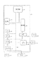
【0351】
本発明は、既に述べた分割および復号する方法を実行する分割を決定するデバイス及び復号するデバイスにも関係する。分割を決定する及び復号するこれらのデバイスは、図15に示すように、コンピュータ50において、独立的に、または同一コンピュータ50内において使用できる。分割決定デバイスは、各領域へ挿入された情報ビットの検出可能性の判定基準に従って適応分割を実施するように構成された分割手段500、502、503を有する。
【0352】
これらの分割手段は、既に述べたように出来るだけ各係数に依存する変調因子Kと共に、前記デジタル画像を表す全ての係数を変調するために透かし信号非感知性を保証する重み付け係数の最大値αvをコード化することを利用する。
【0353】
また、分割を決定するこのデバイスは、分割の各領域のサイズPを前記領域に挿入された透かし信号の検出に関する統計的の有意なサンプルの最小サイズに対応する最小サイズPstatと比較する手段500、502、503も有する。
【0354】
また、本デバイスは、検出可能性の判定基準を算定する以前に予歪みを印加する手段500、502、503も備える。分割手段は、透かし信号を挿入することによって各領域の全ての係数を変調する手段500、502、503、検出可能性の判定基準から検出可能性の範囲を算定する手段500、502、503、および検出可能性の範囲を所定のしきい値Tcと比較するように構成された検出可能性の判定基準の有効性を検査する手段500、502、503を有する。
【0355】
分割手段500、502、503は、数値画像の反復的な区分によって分割を実施するように構成され、有効性検査手段500、502、503は、前記分割における一ランクにおける各領域に関して、検出可能性の判定基準の有効性が確認された領域の少なくとも2つの小領域が存在し、かつ存在する場合に限り当該領域における更に高いランクの分割の有効性を検査するように構成される。
【0356】
また、このデバイスは、分割における一ランクにおける各領域に関して、直接の上位ランクの分割が有効であるとされなかった時に容量値Qをインクレメントするように構成されたデジタル画像の容量Q値をインクレメントする手段500、502、503も含み、この場合の容量Qは、検出可能性の判定基準が妥当であると確認された分割によって得られた区分けされた領域の集合数に等しい。
【0357】
他の実施形態において、分割を決定するこのデバイスは、分割の一ランクにおける各領域Rに関して、直接高位のランクの分割が有効であるとされなかった場合に容量Q値をインクレメントするように構成されたインクリメント手段500、502、503、容量Qの値を固定した容量値Qsと比較する比較手段500、502、503、および容量値Qが固定した容量値Qs未満である時に処理されるべき他の全ての領域の間の最高検出可能性を持つ領域に関して分割を繰り返すように構成された反復手段500、502、503を有する。
【0358】
本発明の第3実施形態において、分割手段500、502、503は、デジタル画像の反復的な結合によって分割を実施するように構成され、かつ、検出可能性の判定基準が有効であるとされなかった分割の各領域に関して、当該領域を分割の他の領域、および、好ましくは検出可能性の判定基準が有効であるとされなかった分割の他の領域と結合するように構成される。
【0359】
各領域の係数を復号することによって得られた情報ビットの検出可能性の判定基準とされる関数に適応した分割によって実施されるように構成された、完全に類似する様式において、デジタル画像内の透かし信号を復号するデバイスは、復号されるべきデジタル画像を区分けされた領域に分割する手段500、502、503を有する。また、それは、分割の各領域Rのサイズ寸Pと当該領域に挿入された透かし信号の検出に関する統計的に有意なサンプルの最小サイズに対応する最小サイズPstatとを比較する手段500、502、503も備える。
【0360】
それは、検出可能性の判定基準から検出振幅を算定する手段500、502、503、および、検出振幅と復号に関する所定のしきい値Tdとを比較するように構成された、検出可能性の判定基準の有効性検査を行う手段500、502、503を有する。
【0361】
復号に関するこの所定しきい値Tdは、既に述べた分割決定方法に際して用いられる所定のしきい値Tc未満である。
【0362】
好ましい実施形態において、分割を決定するデバイスは、各領域全体に渡る当該領域の係数の変調により、ゼロ平均の疑似ランダム数列によって挿入された情報ビットの検出可能性の判定基準をチェックする手段500、502、503を含む。
【0363】
また、それは、画像を表す係数集合のここではNである集合数に等しいサイズであって中心擬似ランダム数列を生成する手段500、502、503も含む。この係数集合に、同じ情報ビットを挿入するために、中心擬似ランダム数列によって係数Xの集合を変調する手段500、502、503も、図1に示すうに、分割を決定するデバイス11に組み込まれる。
【0364】
また、後者(分割決定デバイス)は、通常はデジタル画像の圧縮である特定のタイプの歪みの場合には、それを記憶するために、挿入された透かしの強固さを提供して、それを保証することを可能にする歪みDを印加する手段500、502、503も含む。
【0365】
歪みを印加するこれらの手段は、変調された係数集合全体に亙って所定の歪みをシミュレートすることを実際に可能にする。ここに、集合Xの係数がスペクトル係数である場合には、それらの手段には、透かし入りの画像を得るために変調された係数集合を逆スペクトル変換する手段500、502、503、この透かし入りの画像に歪みを印加する手段500、502、503、および、歪みの後で、変調済み係数集合を復元するために透かし入りの画像をスペクトル変換する手段500、502、503が含まれる。
【0366】
この例において、逆方向スペクトル変換手段は多重解像度スペクトルウェーブレット再合成の実行に適し、順方向スペクトル変換手段はデジタル画像Iのウェーブレットへの分割の再反復に適する。
【0367】
第1の方法において、分割決定デバイス11は、係数X集合の初期区分に基づく反復組合わせによる分割手段も含む。
【0368】
これらの領域全体に渡る検出可能性の判定基準の有効性検査のために統計的に有意なサイズの領域集合に係数X集合を区分することをこの初期区分が可能にすることが好ましい。
【0369】
反復的組合わせによる分割手段500、502、503は、検出可能性の判定基準が満足されない分割の各領域に関して、当該領域を分割の他の領域と組み合わせることに適する。
【0370】
明らかなように、分割手段500、502、503は、本発明の好ましい実施形態を実施する第2の方法に従ったデジタル画像の反復的分割による画像のこの分割を形成することにも適する。
【0371】
この分割決定デバイス11は係数X集合の領域への分割を出力として得ることを可能にし、それにより、信頼できる検出可能性および所与の歪みに対する強固性を保持して、これらの領域の各々に情報ビットを挿入することを可能にする。集合Xの適応分割によって得られる領域の最大個数は、この集合Xの実用的な挿入容量に対応する。
【0372】
図1に示すように、既に述べた分割決定デバイス11を含む挿入デバイス10は、更に、幾つかの情報ビットを含む挿入されるべき透かしを読み取る手段13を有する。一切限定的意味をもたない一例として、2進透かしは、透かしを入れられるべき画像の著者名コード化を表す1000111であっても差し支えない。挿入手段12自体は従来型であって、透かしの各種情報ビットを変調により分割決定デバイス11によって決定される各種挿入キャリヤに挿入することを可能にする。
【0373】
本発明による透かし信号wを挿入するためのデバイスは、画像Iの空間周波数変換手段500、502、503、および、例えば画像Iのウェーブレット分解を実施するように構成された2つのフィルタによってデシメータと関連した分析フィルタを含む。また、それ(前記デバイス)は、サブバンドに変換された領域に透かし信号を挿入した後で、画像Iを再構成する逆方向空間周波数再構成手段500、502、503も含む。
【0374】
また、それ(前記デバイス)は、重み付け係数αを用いる既に述べた線形モデルに従い、集合数Pの係数部分集合を変調するように構成された長さPの透かし信号wを挿入する手段500、502、503も含む。
【0375】
また、この挿入デバイスは、透かし信号の非感知性を保証する透かしの長さPの関数として、重み付け係数の最大値αvを計算する手段500、502、503を含む。これらの計算手段は、既に記述された透かし信号wの長さPに依存する関数αv(P、T)、および画像信号Iを分解するために用いられるスペクトル変換Tを使用する。
【0376】
一般に、この挿入デバイスは、決定された重み付け係数の値が、透かし信号wの長さPおよび検出確率レベルpの決定値に関する最大値αv未満であり、しかも最小値αv以上であるように、透かし信号wの長さP、重み付け係数α、及び確率レベルpの適合可能な値を決定する手段500、502、503も有する。
【0377】
また、計算手段500、502、503も次に示すタイプの計算機能を用いて最小値または検出振幅αDを決定するように構成される。
【0378】
【数27】
本発明の一実施形態において、挿入デバイスは、感知限界における透かし信号wの非感知性を保証する変調可能な係数集合の集合数Nに等しい透かし信号wの長さPおよび所定の検出確率pに関して算定された最大値αv(N)に等しい重み付け係数の最小値αDに関して透かし信号wの長さP°を算定する手段500、502、503、および、この算定された長さP°と変調可能な係数X集合の集合数Nとを比較する手段500、502、503も備える。
【0380】
また、それ(前記挿入デバイス)は、変調可能な係数X集合の集合数Nに等しい透かし信号の長さPに関して算定された最大値αvに等しい重み付け係数の最小値αDに関して得られる検出確率レベルp'を算定する手段500、502、503も含む。
【0381】
他の一実施形態において、挿入デバイスは、重み付け係数の最小値αDがこのしきい値Ptおよび所定の検出確率レベルpに等しい透かし信号wの長さPの重み付け係数の最大値αvに等しいように、決定された透かし信号wの長さのしきい値P*を算定する手段500、502、503を含む。
【0382】
既に述べた全てデバイスはコンピュータ50のマイクロプロセッサ500に組み込まれ、読取り専用メモリ502は分割用、及び/又は、透かし信号決定用、及び/又は、透かし信号復号用プログラムを記憶するように構成され、ランダムアクセスメモリ503は、前記プログラムの実行期間中に修正される変数を記憶するように構成されたレジスタを含む。
【0383】
マイクロプロセッサ500はコンピュータ50に統合され、ドキュメントを受信および記憶するために入力/出力カード506によって、異なる周辺装置、例えば、デジタルカメラ507またはマイクロホン511へ接続可能である。デジタルカメラ507は、透かし信号を挿入することによって認証されるべき画像を供給することを明確に可能にする。
【0384】
このコンピュータ50は、透かしが入られるべき画像を、必要に応じて受け取るために通信ネットワーク513へ接続された通信インターフェイス512を備える。また、コンピュータ50は、ハードディスク508のようなドキュメント記憶手段も備え、ディスクドライブ509によって、ディスケット510のような取外し可能なドキュメント記憶手段と協調するように構成される。
【0385】
これらの固定または取外し可能な記憶手段は本発明に基づく異なる方法のコードを含むことも可能であり、マイクロプロセッサ500によって一旦読取られた前記コードはハードディスク508に記憶される。一例として、デバイスが本発明を実行できるようにするプログラムは読取り専用メモリ502に記憶され得る。第2の例として、プログラムは、上に述べたように、通信ネットワーク513によって受け取り可能である。
【0386】
また、コンピュータ50は、例えばキーボード514または他の任意の手段によるオペレータとのインタフェースとして役立つスクリーン504も備える。中央ユニット500(CPU)は、本発明の具体化に関する命令を実行する。例えば読取り専用メモリ502のような持久メモリによって記憶されている本発明に関係するプログラム及び方法は、電力供給に際して、ランダムアクセスメモリ503(RAM)に転送される。従って、前記メモリは、本発明の実行可能なコードおよび本発明を実行するために必要な変数を含むことになる。
【0387】
このランダムアクセスメモリ503は、当該プログラムの実行に必要な変数を記憶する異なるレジスタ、および、特に、検出可能性の判定基準、最小値Pstat、及び、それぞれ符号化と復号に関するしきい値TcとTdを確認するために一時的に変調または復号される領域Rの係数を記憶するレジスタを含む。また、このランダムアクセスメモリ503は、検出可能性の判定基準をチェックするために一時的に変調または復号される領域の係数を記憶するためのXi、Xjレジスタ、及び、集合Xの分割を決定するために生成された中心擬似ランダム数列を記憶するためのレジスタwも含む。
【0388】
最後に、ランダムアクセスメモリ503は、αbase(T)の視覚的振幅表を記憶するレジスタ、スペクトル係数Xを記憶するレジスタ、非感知性限界における視覚的振幅αv(N)を算定するレジスタ、透かし信号w長P°の関数として検出振幅αDを決定するために必要な分散σx 2の定数a、b、cの値を記憶するレジスタ、及び、算定された最小値P0を記憶するレジスタを含む。
【0389】
通信バス501はコンピュータ50の、又は、それにリンクした異なるサブエレメント間の通信を提供する。バス501の表現は限定的でなく、また、マイクロプロセッサ500は、明確に、あらゆるサブエレメントに対して直接的または他のサブエレメントによって命令を指示すことができる。
【図面の簡単な説明】
【図1】透かしをデジタル画像に挿入するデバイスを示す全体的なダイアグラムである。
【図2】透かしの挿入に際して用いられるスペクトル分解のステップを概略的に示す図である。
【図3】本発明の第1実施形態に係る分割を決定する方法のアルゴリズムを示す図である。
【図4】領域の分割の例を示す図である。
【図5】本発明の第2実施形態に係る分割を決定する方法のアルゴリズムを示す図である。
【図6】本発明の第1実施形態に係る復号する方法のアルゴリズムを示す図である。
【図7】図1の分割を決定する方法のデジタル画像への適用を例示するアルゴリズムを示す図である。
【図8】図4の復号する方法のデジタル画像への適用を例示するアルゴリズムを示す図である。
【図9】本発明の第3の実施形態に係る分割を決定する方法の異種実施形態を示す構成図である。
【図10】本発明の好ましい実施形態に係るデジタル画像への分割を決定する方法の適用を示す図である。
【図11】本発明の好ましい実施形態の第1の方法に係る分割を決定する方法のアルゴリズムを示す図である。
【図12】本発明の好ましい実施形態の第2の方法に係る分割を決定する方法のアルゴリズムを示す図である。
【図13】本発明の一実施形態に係る挿入方法のアルゴリズムを示す図である。
【図14】図13の挿入方法をグラフとして示す図である。
【図15】本発明による方法を実行するように構成されたデバイスを示す構成図である。[0001]
BACKGROUND OF THE INVENTION
The present inventionTechnology for inserting watermark information into images.
[0002]
[Prior art]
Watermarking digital data makes it possible to protect these data, for example by associating data with copyright information. In principle, watermarking consists of inserting a permanent watermark into the digital data, which can be compared to encoding additional information as data. Decoding this additional information makes it possible to check the inserted copyright information.
[0003]
This inserted watermark must consequently be insensitive and robust to the specific distortion applied to the digital image and still be detectable with high confidence. Conventionally, a common technique for inserting a watermark signal into a digital image consists of using a linear modulation model in which at least one subset of coefficients representing the digital image is modulated according to this linear model using weighting factors.
[0004]
A set of coefficients representing at least a portion of the digital image is X = {Xi, 1 ≦ i ≦ N}, and a watermark of size P ≦ N is represented by w = {wj, 1 ≦ j ≦ P}, the following is a linear insertion formula for a pseudo-random signal with known distribution and zero mean:
X 'j= Xj+ BαjwjHowever, 1 ≦ j ≦ P
Where {Xj, 1 ≦ j ≦ P} is a subset of the set of coefficients X, b is one information bit, αjIs a weighting coefficient also called modulation amplitude.
[0005]
Thus, watermark detection consists in detecting whether a pseudo-random sequence w has been inserted into the set of coefficients. This detection can be performed without using the original image and can be based on standardized statistical tests that allow the probability of correct detection to be calculated. Since the response from the detector is binary (yes / no), this type of insertion technique allows one single piece of information to be inserted by watermark insertion.
[0006]
In order to insert a relatively large number of information bits into a digital image, particularly if one Q-bit code indicating the name or address of the owner or author of the image is needed, for example. It is necessary to repeat the previously described insertion method every time there is a power information bit. Generally, either b1 or b-1 is used to insert a binary signal.
[0007]
In another method, it is assumed that Q coefficient subsets are selected and modulation of these subsets must be performed by selecting Q watermarks. The individual subsets of coefficients are preferably selected so that the modulation operations do not overlap each other. In this case, overlapping modulation operations can interfere with detection or cause tedious visual effects. Thus, the above selection represents the problem of selecting a method for dividing a coefficient representing a digital image into Q individual subsets. Here, each subset carries one information bit.
[0008]
[Problems to be solved by the invention]
Many known methods use techniques to insert a watermark signal of a given size by spectral extension. Regarding these methods, for example, “Secure spread spectrum watermarking for maultimedia” by IJCOX et al. (Proceedings, ICIP, pages 243-246, September 1996), “Digital watermarking of raw and compressed video by F.HARTUNG et al. (Proceedings, SPIE 2952), "Digital Compression Technologies and Systems for Video Communication" (pp. 205-213, October 1996). The disadvantage of these methods is that techniques are used to arbitrarily divide the image into fixed size blocks without any guarantee of the detectability of the modulation performed on each block.
[0009]
The purpose of the present invention is toWatermark information to be inserted into the imageThe detectability ofTestifyThere is to be.
[0060]
[Means for Solving the Problems]
The image processing method of the present invention includes:A dividing step in which the dividing unit divides the image and sets a divided region, and a determining unit determines the number of the divided regions by the number of the divided regions divided in the dividing step.Insert into image dataBe doneWatermark informationMaximum number of bits of information represented byA determination step for determiningThus, in the dividing step, for the data in which watermark information is inserted for each divided region and distortion due to compression is applied, the image is converted to 4 within a range in which the detectability of each inserted watermark information is not less than a specified value. It is characterized by dividing the tree.
[0063]
The image processing apparatus of the present invention isA dividing unit that divides an image and sets a divided region, and a number of the divided regions divided by the dividing unit,Insert into image dataBe doneWatermark informationMaximum number of bits of information represented byDetermining means for determiningThe dividing means divides the image into four parts within a range in which the detectability of each inserted watermark information is equal to or greater than a predetermined value for data in which watermark information is inserted for each divided region and distortion due to compression is applied. It is characterized by tree division.
[0096]
Moreover, according to the present invention,A storage medium storing a program for causing a computer to execute the image processing method is provided..
[0097]
Other particularities and advantages of the invention will also become apparent from the following description of the invention. In the accompanying drawings, examples are given that have no limiting meaning.
[0098]
DETAILED DESCRIPTION OF THE INVENTION
First, a description will be given with reference to FIG. 1 regarding watermark insertion into a set of coefficients representing a digital image I. FIG.
[0099]
This digital image I can be represented by a set of coefficients in either the spatial domain or the transform domain. The coefficient in the latter case is a hybrid coefficient, i.e. a coefficient located in both the spatial and frequency domains. This type of image representation is determined using subbands resulting from the spatial-frequency decomposition of the image, such as discrete wavelet decomposition.
[0100]
In this case, watermark insertion is achieved via an extended spectral insertion technique by modulation of coefficients of the space-frequency representation of the image obtained by the space-frequency transformation of the digital image I.
[0101]
As an example, the discrete wavelet decomposition S represented schematically in FIG. 2 can be used. Since this space-frequency decomposition is well known in the field of image processing, only its principle will be reviewed below. Said decomposition makes it possible to divide the image into frequency subbands and to obtain hybrid coefficients, i.e. spectral coefficients which are also located in a space which in this case is in the plane.
[0102]
Image I consists of a series of digital samples. The image I is represented, for example, by a series of bytes, each byte value representing one pixel of the image I, which can be a black and white image having 256 gray levels.
[0103]
The multi-resolution spectral decomposition means consists of a subband decomposition circuit or analysis circuit formed by a set of analysis filters each associated with a divider by two. This decomposition circuit filters the image signal I in two directions into high spatial frequency and low frequency subbands. The circuit includes several successive analysis blocks that classify the image I into subbands according to several resolution levels.
[0104]
As an example, in this case, it is assumed that the image I is classified into subbands whose decomposition level d is equal to 3.
[0105]
The first analysis block receives the image signal I and filters it in a first direction, for example the horizontal direction, through two respective low-pass and high-pass digital filters. After passing through the divider by 2, the resulting filtered signal is then filtered in a second direction, eg, the vertical direction, by two respective low pass and high pass filters. Each signal is again passed through the divider by 2. Thus, four subbands LL1, LH1, HL1, HH1 are obtained at the output of this first analysis block with the highest resolution in the decomposition.
[0106]
The subband LL1 includes low frequency components in two directions of the image signal I. The subband LH1 includes a low frequency component along the first direction and a high frequency component along the second direction of the image signal I. The subband HL1 includes a high frequency component along the first direction and a low frequency component along the second direction. Finally, the subband HH1 includes high frequency components along two directions.
[0107]
The second analysis block then filters the low frequency LL1 subbands in the same manner to provide four subbands LL2, LH2, HL2, HH2 with intermediate level resolution in the decomposition. The third analysis block then filters the low frequency LL2 subbands to provide four subbands LL3, LH3, HL3, HH3. In this example, finally, subband LL3 is analyzed by the fourth analysis unit to provide four subbands LL4, LH4, HL4, HH4 with the lowest resolution in this decomposition.
[0108]
Thus, 13 subbands and 4 resolution levels are obtained. As can be seen, the number of resolution levels, and thus the number of subbands, can be selected differently. As will be apparent, other types of spectral transformations can be used such as, for example, a discrete Fourier transform, a discrete cosine transform, or a Fourier-Merlin transform.
[0109]
In a general manner, frequency subbands are obtained by forming a set of spectral coefficients into which a watermark can be inserted. Here, the high frequency subband of the highest resolution HH1 can be considered in order to insert the watermark. Thus, this subband HH1 supplies, for example, a set of coefficients X whose size is equal to N.
[0110]
A set of coefficients representing the digital image I is expressed as X = {Xi, 1 ≦ i ≦ N}. As should be apparent, it should be possible to consider a subset of the coefficients of this set X that represents only a part of the digital image I.
[0111]
One technique for inserting a watermark into this set of coefficients X inserts a pseudo-random signal by expanding its spectrum so that the pseudo-random signal is undetectable by spectral or statistical analysis. That is.
[0112]
w = {wj, 1 ≦ j ≦ P} is a watermark of size P ≦ N, that is, a pseudo-random signal whose superfunction is known and whose average is zero. The most extensive superfunctions are the binary superfunction {-1, 1}, the superfunction over the entire [-1, 1], and the central normalized Gaussian superfunction N (0, 1).
[0113]
The linear insertion formula is shown below.
[0114]
X 'j= Xj+ BσjwjHowever, 1 ≦ j ≦ P
Where {
[0115]
In order to insert a signal that can be formed from several information bits, it is worthwhile to divide the set of coefficients so as to determine the number of regions or the number of inserted carriers available in this set. To implement it, the insertion device 10 according to the invention includes a device for determining the division 11 and the insertion means 12.
[0116]
The device for determining the partition 11 is suitable for performing an adaptive partition of the set of coefficients as a function of the detectability of the inserted watermark. This method of performing adaptive segmentation changes the number of coefficients that are modulated to insert the information bits of the watermark so as to simultaneously satisfy the respective criteria set for invisibility and proper detection probability. It is in.
[0117]
First, referring to FIG. 3, the division of the digital image into segmented regions which makes it possible to maximize the number of regions determined to maximize the number of information bits inserted into the image. A method of determination will be described.
[0118]
Consider the representation of a digital image by a set of coefficients in either the spatial domain or the transform domain, i.e. both the spatial domain and the frequency domain. However, in the case of the transform domain, the coefficient is a hybrid. This type of image representation is determined as the discrete wavelet decomposition already described, for example, by using the subbands that diverge from the image space and frequency decomposition.
[0119]
Image segmentation is performed to insert a watermark signal by modulating the coefficients of each region. According to the invention, the division into this area is performed by adaptive division as a function of the criterion of the detectability of the information bits inserted into this area. The number of regions determined under the constraint conditions of the detectability criterion makes it possible to define the maximum capacity of the digital image. This maximum capacity corresponds to the number of information bits that can be inserted into the digital image with the condition that it meets the detectability criteria.
[0120]
Initially, in step E100, this capacity Q is initialized to 0, and the starting point is an initial division, here limited to a single region R of size P. Of course, the initial partition can be different and already contains several partitioned regions that may be different in size. The size P of this initial region R is P corresponding to the minimum size of a statistically significant sample of coefficients.statIt is assumed that it is larger than the minimum size represented by In general, this minimum size can be fixed at 100. This initial region R can consist of a set of coefficient representations under consideration or a subset of this representation.
[0121]
Next, the test step E101 checks the detectability of the watermark signal inserted in the initial region R. This detectability check is performed by the actual modulation and detection operations on the coefficients of the initial region R. Actually, all the coefficients of the initial region R are copied to the working memory so as not to directly watermark the image.
[0122]
Next, all coefficients in the initial region R are modulated by inserting a watermark signal. To carry out this modulation, the following procedure is followed as before:
If the initial region consists of one coefficient set:
X: {Xi, I = 1,. . . P}
Typically, the following types of linear modulation are used:
Xi *= Xi± αiWiHowever, i = 1,. . . , P
Where W: {Wi, I = 1,. . . , P} is a watermark signal selected as a pseudorandom sequence with a known distribution and an average of zero.
[0123]
The ± sign value of the modulation depends on the binary value to be inserted: for example, the-sign value corresponds to the value 0 and the + sign value corresponds to the
[0124]
Of course, any pseudo-random watermarking with known distribution and mean zero may be appropriate. The most common distributions for the watermark signal W are the binary distribution {-1, 1} and the central standardized Gaussian distribution N (0, 1) apart from the uniform distribution [-1, 1]. The modulation can optionally be protected, for example, by a secret key that characterizes the nucleus for reproducing the pseudorandom sequence W.
[0125]
αiThe term is the coefficient XiIs the modulation amplitude or weighting factor applied to A constant weighting factor is for all coefficients in region R, for example α for every ii= ΑvCan be used. In this case, the weighting factor αvIs equal to the maximum value that guarantees the insensitivity of the watermark signal to the modulation of the set of coefficients representing the digital image.
[0126]
This maximum value αvThe minimum noticeable difference (referred to as JND amplitude) actually decreases with the length of the sequence of the watermark signal W and thus with the number of coefficients that can be modulated. If the capacity Q is to be maximized when all the coefficients of the digital image representation are used for modulation, determine the modulation JND amplitude for a number of modifiable coefficients equal to the number of coefficients representing the image. Is wise.
[0127]
This maximum value αvOr, the JND amplitude corresponds to the maximum modulation amplitude that can be used in the above-described linear insertion model, above which changes in the reconstructed watermarked image can be visually detected by the viewer.
[0128]
In order to determine this JND amplitude, different parameters are used: the representation of the number through the space-frequency transform S used, the subbands considered for insertion, the type of distribution of the watermark signal sequence W, and the sequence It is possible to use a visibility model that makes it possible to predict the visibility of the watermarking operation based on the length P of W.
[0129]
A simple model developed by WATSON and described in a paper entitled “Visibility of wavelet quantization noise” (AB WATSON et al., IEEE Trans. On Image Process 6 (8), 1164-1175, 1997) is 1 Allows visibility prediction of a set of modulated coefficients from measurements of two single modulated coefficients. This document can be advantageously referred to for a detailed description of this model.
[0130]
Thus, depending on the length P of the watermark signal W, the type of transform S used and the (basic) subband to be considered for insertion, a function independent of all the coefficients X to be watermarked is utilized. .
[0131]
The calculation function used is as follows:
[0132]
[Equation 8]
β is strictly greater than 2, E [| w |β] Is a function | w |βIs the mathematical expectation of
[0133]
Base value αbase(S) can be measured for all once from a single psychovisual measurement for each subband of coefficients in the wavelet decomposition and can be stored in a visual amplitude table. β is an exponent of the power of the Minkowski sum, and can be selected as 5, for example. Mathematical Expectation E [| w |β] Is a function | w |βCorresponds to the average estimate of.
[0134]
This visibility model does not consider the image I that is watermarked in itself and is therefore independent of it. This is equivalent to considering the image I to be uniform. This is a problem of the “worst state” model, as the presence of the image signal allows it to visually mask its own modulation.
[0135]
Therefore, the JND amplitude can be calculated with respect to the length P of the watermark signal W equal to the number of sets of all modifiable coefficients of the subband under consideration. However, it is advisable to take advantage of the fact that the image signal itself allows the modulation to be masked.
[0136]
Thus, in this example, each coefficient X to be modulatediWith respect to the formula αi= Ki.αvA weighting factor according to the law is used. Where kiIs a modulation coefficient that depends on the coefficients located near the coefficients considered on the region R, and αvIs equal to the maximum JND value of the weighting factor.
[0137]
Thus, each coefficient is modulated according to local content, allowing the modulation amplitude to be increased locally to the extent that a detectability benefit is obtained.
[0138]
Next, in order to inspect the detectability in the inspection step E101, the detectability range is calculated from the detectability determination criteria, and the detectability range and a predetermined threshold value represented by Tc Are compared to test this detectability criterion.
[0139]
All modulated coefficients X*And the correlation C (X*, W) is generally calculated and the correlation (X*, W) If the result of the calculation is greater than a predetermined threshold Tc, it is determined whether the watermarking of the image has actually been performed.
[0140]
For example, the standardized statistical test described in “A method for signature casting on digital images” by I.PITAS (Proceedings: ICIP, pages 215-218, September 1996) can be used for detection. . The detection is then characterized with respect to probability. Therefore, it is possible to select a threshold value Tc corresponding to a fixed detection probability level, for example 99.95%.
[0141]
Therefore, the range of detectability is calculated for a given region R that defines a set of coefficients P of size P with a fixed weighting factor α, and whether the detectability criterion on this region R is valid. In order to check, the calculation result is compared with the threshold value Tc.
[0142]
The detectability criteria are actually the size P of the region R, the detection threshold Tc related to the required detection probability, the watermark signal W, the variance σ 2x of the coefficient X to be modulated in the region R and , A theoretical function depending on the weighting factor α used to modulate the factor X based on the linear model described above.
[0143]
Thus, for example, the standardized hypothesis test and all the coefficients X in region RiΑvFor a detection with a weighting factor α of a value equal to and constantmin(X) is defined by the following function.
[0144]
[Equation 9]
[0145]
Upon decoding, the set of coefficients X is modulated and this function is also the variance of the inserted watermark σ2 wDepends on.
[0146]
Furthermore, it is necessary to deal with any distortion that may occur in the image after modulation, for example due to image compression.
[0147]
If this noise is considered additive and uncorrelated with the coefficients, then this additive noise variance σ that models any distortion applied to the modulated coefficients2 qIt is possible to use models that depend on.
[0148]
Thus, for a given weighting factor α, the watermark signal to be inserted, the detection threshold Td fixed as a function of the detection probability required for decoding, and the invisibility of a set of selected coefficients X The minimum modulation length P which makes it possible to guarantee the detectability of the inserted watermark signal in this case as well.minCorresponds to (X).
[0149]
Upon decoding, this minimum length P for detection by standardized hypothesis testingmin(X) is defined by a function as follows:
[0150]
[Expression 10]
[0151]
Therefore, if the same detectability test is used for encoding and decoding, the encoding threshold value is larger than Td used for decoding so that the same division can be found when decoding the image. It is necessary to select Tc.
[0152]
In practice, the threshold value Td to be used for decoding is fixed to the detection probability level required when detection is performed by standardized hypothesis testing, for example, the variance in the watermark signal W, and the image In order to consider the additive noise variance fixed a priori so as to predict the effect of subsequent processing on the higher threshold Tc is chosen during encoding.
[0153]
This condition thus makes it possible to find the same detectability criterion that constrains the division of the digital image without communicating to the decoder the division carried out when the watermark signal W is inserted.
[0154]
In this exemplary embodiment, segmentation by iterative segmentation of the digital image is performed. Therefore, in step E101, it is considered that the determination criterion for detectability is satisfied when the calculated detection-amplitude is equal to or greater than the predetermined threshold value Tc.
[0155]
If the detection criterion is not satisfied, the detection probability generally decreases with the size of the region. Therefore, even in the small region (subregion) of the initial region R having a smaller size, The possibility of not being satisfied should be great. Step E102, which stops the method for determining the division, makes it possible to stop the iterative division process of the image.
[0156]
If it is not determined that the insertion in the initial region R is possible, the image capacity Q is therefore zero. On the other hand, when the detection criterion is satisfied, that is, when the detection amplitude is equal to or greater than the threshold value Tc, the detection criterion is satisfied even for the small region of the initial region R. It is possible that
[0157]
Therefore, as long as the detectability criterion is satisfied, it is advisable to try to divide the region R in order to increase the capacity Q. Of course, the size P of the region RjSmall region RjThere are several means by which the spatial partitioning can be performed. Where j = 1,. . . K. In this example, a quadtree as shown in FIG. 4 is selected. This partitioning method consists of dividing each region into four small regions of the same size.
[0158]
Accordingly, as shown in FIG. 2 as an example, an initial size N digital image is composed of two small regions R5 and R6 of size N / 4 and seven small regions R1, R2, R3, R4 of size N / 16. , R74, R8, R9 and four small regions R10, R11, R12, R13 of size N / 64.
[0159]
Therefore, in the segmentation step E103, the region R has the size PjSmall region Rj, J = 1,. . . , K. When dividing into quadtrees, K = 4 and Pj= P / 4.
[0160]
In step E104, the first subregion with index j (eg j = 1) is considered and GQThe value of the potential gain in the capacity represented by is initialized to -1. The division determination method is the region RjSize PjAs described above, the minimum size P corresponding to the minimum size of the samples that is statistically significant for the detection of the watermark signal inserted in the region as described above.statStep E105 before the comparison is included.
[0161]
Region R at step E108jSize PjIs this minimum size PstatIf it is less than the following subregion RjTo process +1, the index J = J + 1 is incremented.
[0162]
If this is not the case, the subregion R is processed in the same way as already described with respect to step E101.jThe detectability criterion in is checked.
[0163]
In practice, the watermark signal is the region RjAnd the detected amplitude is calculated, and this range of detectability is compared with the threshold value Tc. Detection amplitude is modulated signal X*And a correlation value between the carrier of the watermark signal W or the result of a standardized hypothesis test. When the detection criterion is confirmed, the capacity GQThe value of the potential gain at is increased by one unit at step E107.
[0164]
Next, in step E108, the index j of the small area is incremented, and it is checked in the test step E109 that this index j is less than or equal to the number K. If affirmative, steps E105 to E109 are repeated on the next subregion.
[0165]
Otherwise, if the index j = K + 1, the capacitance value GQAt least two regions R of the initial region R for which the potential gain atjIs checked in the test step E110.
[0166]
If not, the higher rank division performed on the initial region R is not confirmed and this region R is preserved. This is an arbitrary subregion RjOr one single small region RjThis is a case where the determination criterion for detectability is not confirmed.
[0167]
In the latter case, the size P is the identified single subregion RjTherefore, it is preferable to hold the region R for inserting a watermark signal.
[0168]
Next, in step E112, the value of the capacity Q is increased by one unit, and the region R of size P in the division is held.
[0169]
Next, the actual insertion step E113 by modulation of the coefficients of the region R is performed in the usual way using the linear insertion model already described.
[0170]
The removal step E114 then makes it possible to remove the region R from the stack of regions to be processed.
[0171]
On the other hand, if the value of the potential gain capacity Gc is strictly positive in step E110, in the additional step E111, all of the detection criteria relating thereto are confirmed in the stack of the region R to be processed. Small region RjIs added.
[0172]
The return step E115 makes it possible to repeat all the steps from step E103 to E113 in order to process the areas of the stack in an iterative manner.
[0173]
At the end of the above iterative division method, a capacity value Qm corresponding to the maximum image capacity for inserting the watermark signal is determined, ensuring correct detection of this signal. This maximum capacity Qm is equal to the number of sets of segmented areas obtained by the above-mentioned division in which the detection criterion is confirmed.
[0174]
Furthermore, the insertion step itself E113 can be omitted during the first “pass”, which makes it possible to determine only the maximum capacity Qm and the confirmed region of the image. Once the maximum capacity Qm is calculated and the corresponding partition is stored in the memory, the user determines the message to be inserted corresponding to the number of information bits equal to the maximum capacity Qm and is obtained by the previously determined partition. It is possible to insert this message in the usual way by modulating the coefficients of the different regions specified.
[0175]
Now, with reference to FIG. 5, a second embodiment of the present invention in which a message of fixed capacity Qs is to be inserted into the image I will be described. Of course, this fixed capacity Qs must be less than the maximum capacity Qm of the digital image to be watermarked.
[0176]
As shown in FIG. 5, the method for determining the division in this embodiment includes steps E100 to E113. These steps are the same as the method steps for determining the partitioning of the embodiment of FIG. 3 and need not be described again here. When the division of the adjacent higher rank is not confirmed as in the previous case, the value of the capacity Q is incremented in step E112.
[0177]
Next, the method includes a comparison step E116 in which this value of the capacitance Q is compared with the fixed capacitance value Qs. In practice, in step E116, it is checked whether the capacitance value Q is equal to the fixed capacitance value Qs.
[0178]
If it is positive, the stop step E117 makes it possible to stop the iterative division of the image, since there are as many regions as the number of information bits Os to be inserted. Otherwise, in removal step E114, the processed region is removed from the stack of regions R to be processed formed in step E111.
[0179]
In this embodiment, the method for determining partitioning also includes a classification step E118 that classifies the region R to be processed in the stack according to the range of detectability calculated for these regions R. Accordingly, the return step E115 repeats the division from the partitioning step E103 for the in-stack region R that has the highest range of detectability among all other regions to be processed.
[0180]
A variant for classification consisting of classifying regions to be processed according to an order of decreasing size is also possible so that the largest region with a priori better detectability is preferentially processed. Of course, segmentation by iteratively combining digital images can be performed, for example, in the same way using a quadtree segmentation structure as well.
[0181]
Next, the initial partition is the previously defined minimum size PstatAs described above, the area is constituted by a relatively small allowable size area. In the case of each area constituting a division for which the detection criterion of detectability is not confirmed, this area is merged with other areas belonging to the division.
[0182]
This other region belonging to the division is a region where the detection criterion is not confirmed so as to increase the capacity if possible. Alternatively, yet another region may be a region that satisfies the detectability criteria to make the detection reliable.
[0183]
There are many possibilities for selecting the regions to be combined. The detection amplitude calculated for each region can be used as a combination criterion, for example, a region associated with the lowest detection amplitude can be combined.
[0184]
In this particular case of join in a quadtree partitioning structure, joining is structurally constrained and whether it is four adjacent blocks, eg R1, R2, P3, R4 in FIG. 4 must be joined. It is constructed by determining whether or not it must be done.
[0185]
With reference to FIG. 6, we will describe a related decoding method that makes it possible to find a division when a watermark signal inserted in a digital image is extracted. In practice, this segmentation is not known a priori at the decoder because it is a segmentation application to a digital image.
[0186]
Thus, the decoding method is generally constructed by testing all the allowed divisions. The same iterative execution technique is used as used when the partition for inserting the watermark is determined.
[0187]
Accordingly, an embodiment as an example in the case of partitioning by block-by-block division in a quadtree that is symmetric when using the partition determination method of the embodiment described with reference to FIG. 3 will be described.
[0188]
In the initialization step E200, initial division limited to a single region R of size P is performed. This area consists of all the coefficients included in the same digital image representation used when the watermark signal is inserted.
[0189]
As described above, the inspection step E201 is performed such that the size P of the initial region R is the minimum size P.statIt is possible to check that it is actually bigger than.
[0190]
If it is affirmative, in step E203, the criterion for the detectability of the information bits obtained by decoding the coefficients in this region R and inserted into the region R is confirmed. Actually, the detection amplitude is calculated for all the coefficients in the region R, and the detection criterion is confirmed by comparing this detection amplitude with a predetermined threshold value Td relating to decoding. It can be continued by standardized statistical tests and comparison of the results with a predetermined threshold Td.
[0191]
As previously explained, if the same detectability test is used for encoding and decoding, the same distribution can be found for image restoration even when noisy composites are performed by post-processing. When trying to do so, it is necessary to select a coding threshold value Tc larger than Td used for decoding.
[0192]
This condition thus makes it possible to find the same detectability criterion that constrains the division of the digital image without communicating the division performed when the watermark signal W is inserted to the decoder.
[0193]
If the detection criterion is not confirmed in step E203, the size P of the region R is determined in step E204.jSmall region RjDividing into Where j = 1,. . . , K. Next, on encoding, i.e. in this example four subregions R of the same size.jThe same divided structure as that used for dividing the region R into the regions is used.
[0194]
Next, in an additional step E205, a small region R is added to the stack of regions R to be processed.jIn a return step E202, the decoding method is recursively repeated from the test step E201 to each region R of the stack.
[0195]
In the step of calculating the detectability criterion E203, if the latter is confirmed for the region R, the information bit inserted in the region R is inserted in the digital image I in the extraction step E206. It is extracted as an element. This extraction is performed in a conventional manner by calculating the detected amplitude. The result of the test gives the absolute value of the detected amplitude to be compared with the decoding threshold Td. In this case, the code gives the
[0196]
Note that this extraction is already partially performed during the detection step E203, so that the detection step E203 and the extraction step E206 are structurally coupled.
[0197]
In order to remove the region R from the stack of regions to be processed formed in the adding step E205, a removal step E207 is performed, and then the return step E202 is a decoding method for each region R of the stack to be processed. Can be performed iteratively.
[0198]
Now, with reference to FIGS. 7 and 8, a practical application of the method for determining the division of a digital image in a specific embodiment of the invention will be described. In this application, the watermark signal is inserted by means of spectral extension insertion techniques by modulating the coefficients of the space-frequency representation of the image obtained by the space-frequency transform S of the digital image I, as already described with reference to FIG. Is done.
[0199]
In general expression, J = 1,. . . , M using SjA subband is obtained. In this case, M in the conversion step E300 is equal to 13.
[0200]
Next, each subband S of index j considered in step E301jWith respect to FIG. 3, the division is performed in step E <b> 302 by performing the method for determining the division already described with reference to FIG. Thus, the capacity QjIs each subband SjIs derived.
[0201]
Next, the insertion step E303 by modulation of the coefficient is QjConfirmed Q of information bitjAllows insertion into the region.
[0202]
Next, in steps E304 and 305, all subbands SjSubsequent subbands are considered and capacity QjE302 and E303 for dividing and inserting the watermark signal of each subband SjRepeated.
[0203]
Next, each subband SjCapacity Q calculated forjInverse transform S-1 is applied to the image to obtain a watermarked image with a total capacity Q equal to the sum of.
[0204]
Thus, each subband of the representation is considered independently with respect to adaptive partitioning to be performed in both encoding and decoding.
[0205]
As shown in FIG. 8, the decoding method in this embodiment is performed in a similar manner using the decoding method described with respect to FIG. 6, where the initial region R corresponds to a subband of image decomposition each time.
[0206]
Step E400, which is the same as step E300, represents image I with j = 1,. . . , M when SjDivide into subbands.
[0207]
First subband SjAre considered in step E401. The processing order of subbands is the same as the order used for encoding for extracting sequentially inserted messages.
[0208]
The adaptive split is subband SjCapacity QjIs performed in a division step E402 for calculating. Next, in extraction step E403, QjThe information bits are QjExtracted by decoding region coefficients.
[0209]
In test steps E404 and E405, it is checked in the normal way that all subbands have been processed, and conversely, decoding steps E402 and E403 (division and extraction) are repeated for the remaining subbands.
[0210]
In this way, a Q-bit message is obtained at the output of the decoder. Where Q is each subband SjCapacity QjIs equal to the sum of
[0211]
In a variation of the method shown in FIG. 9, it is possible to perform a division on the post-processed image signal to obtain a priori robustness of the watermark signal for any post-processing that the image undergoes.
[0212]
This variant principle consists at this stage by performing a detectability test in the test step E309 which is not coupled to the previously described split E302 and insert E303 steps.
[0213]
In order to find the watermarked image after inserting the watermark signal into the region, firstly the inverse transformation S-1 is performed in step E306. Next, in step E307, post-processing such as digital image compression is applied.
[0214]
Next, transform S is repeated in step E308 to find a watermarked coefficient created in a noisy state if possible by performing post-processing on the image in step E307, and a detectability criterion. Is calculated as previously described.
[0215]
In this case, steps E300 to E309 are repeated for another permissible division of the image, for example by dividing the relevant region R into four, and in step E309 a detectability test is performed on the four subregions. The
[0216]
Only if this division represents a gain in capacity, in other words, in this example of a quadtree partition, this division is only adopted if the detectability criterion is confirmed in at least two subregions. The This variant embodiment makes it possible to directly consider the post-processing applied to the digital image.
[0217]
Now, with reference to FIG. 10, a method for determining a division according to a preferred embodiment of the present invention will be described. It is assumed that a method of inserting a watermark into the digital image I is adopted. The insertion method first includes a method of determining the division of a set of coefficients representing the digital image I.
[0218]
This division is applied to each region of the division as a function of the criterion of the detectability of the inserted information bits. Note that in practice, with regard to watermark insertion, it is possible to search for a division of the digital image into regions that satisfy the maximum number of detectability criteria so as to ascertain the actual capacity of this image. This maximum capacity of the digital image corresponds to the number of information bits that can be inserted into the digital image and at the same time meets the detectability criteria.
[0219]
For a given watermark, provided that it contains the given number of information bits less than the maximum capacity of image I, the best possible guarantee of the invisibility of the inserted watermark in the largest possible size region It is also possible to search for the best possible division of image I that allows the insertion of a watermark of a given length for the detection probability.
[0220]
The method for determining the division first comprises the previously described (discrete wavelet transform or DWT) wavelet decomposition type spectral decomposition step E500. Accordingly, a spectral coefficient X representing the digital image I is obtained. These spectral coefficients are allocated to frequency subbands as shown schematically in FIG. 2 upon completion of the decomposition step E500. The size of the set of coefficients X is equal to N = M × M for a square image. As is apparent, the same method can be applied to rectangular images.
[0221]
In this embodiment of the invention, the method includes a step E501 of generating a central pseudorandom sequence of size N equal to the number N of sets of coefficient X sets representing image I. This pseudo-random sequence is w = {wmn, 0 ≦ m, n ≦ M}.
[0222]
This pseudo-random sequence w is the central pseudo-random sub-sequence wkFormed from. The pseudo-random sequence is the pseudo-random sub-sequence wkIt can be regarded as a combination of In this case, the central pseudo-random sequence w is a pseudo-random sub-sequence w of the same size corresponding to a block of coefficient X set called a unit block.kFormed from. As can be seen, the pseudo-random subsequence wkThe sizes are different from each other.
[0223]
In this case, the size of these unit blocks corresponds to the minimum number of coefficients suitable for forming a region having a statistically significant size in order to satisfy the detection criterion for the entire region. As will be discussed later, when a standardized statistical detection test is applied to a coefficient set, a minimum number of coefficients is required for this test to be significant.
[0224]
Pseudo random sub number sequence wkIs equal to or greater than this minimum number of coefficients, A = L × L. A pseudo-random sub-sequence w of size equal to this minimum sizekIs preferably selected. This property is particularly advantageous when segmentation is achieved by iterative combination by combining blocks from the initial segment of the image into unit blocks of size LxL. Therefore, the initial segment corresponds to the maximum division of the applicable image. Beyond this maximum division, the generated block of coefficients is no longer statistically significant with respect to information bit insertion and detection. For example, assume that L = 8 is selected. In this case, the pseudo-random sequence w is N / 64 pseudo-random sub-sequences w forming unit blocks.kIt is a conjugate of.
[0225]
According to the present invention, for each unit block, a central pseudo-random signal of a predefined distribution (Gaussian distribution, uniform distribution, etc.) must be generated based on a function that depends on the secret key K and the index k of each unit block. I must. This key can be displayed as f (K, k). Next, in practice, the signal w over the entire unit blockkIt is necessary to ensure that the mean of is exactly equal to zero.
[0226]
The first method of generating this kind of central pseudo-random number sequence is constructed by centering the number sequence by a deterministic method by symmetrization. This method is suitable for the generation of an even size A pseudo-random sequence.
[0227]
In this case, each central pseudo-random sub-sequence wkGenerates half A / 2 of the pseudo-random samples of the sub-sequence through a known centrally distributed pseudo-random number generator and generates the pseudo-random sub-sequence wkIs created by symmetrizing the pseudo-random samples generated in this way to obtain the other half A / 2 of the samples.
[0228]
Therefore, in the case of a single-dimensional sequence, the size A / 2 {wj, 1 ≦ j ≦ A / 2) a set of samples is generated, which is the other half of the samples {wj= -WA-j, A / 2 <j ≦ A).
[0229]
In order to enhance the random characteristics of the sequence obtained in this way, the sample set {wj, 1 ≦ j ≦ A).
[0230]
A second method for generating a central pseudo-random number sequence is to generate pseudo-random samples via a pseudo-random number generator and redistribute the sum of these pseudo-random samples generated across each sample. Each central pseudo-random sub-sequence wkComposed by making.
[0231]
Therefore, first of all, by using the secret key f (K, k), a series of pseudo-random samples of the same size A as the unit block, ie {wj, 1 ≦ i ≦ A) is generated. Next, the exact sum of these samples is calculated:
[0232]
## EQU11 ##
[0233]
Thus, the pseudo-random sequence w is a sub-sequence w with center in a way that the division of the coefficients modulated by the central pseudo-random sequence w results in a subset of the coefficients modulated by the central pseudo-Sandum sub-sequence as well.kConsists of a combination of As will be apparent, other techniques can be used to generate a random sequence with a center.
[0234]
Next, as shown in FIG. 10, in order to insert information bits into the coefficient set generated from the spectral decomposition, step E502 of modulating the coefficient set by the central pseudo-random number sequence w is executed. In practice, the coefficient set is copied to a working memory such as a random access memory of a computer so as not to mark the image I directly.
[0235]
The same information bits are modulated into a coefficient set, for example in this case b = 1, based on the following modulation theory:
[0236]
X 'i= Xi+ ΑiwiHowever, 0 ≦ i ≦ N.
[0237]
Weighting amplitude αiAre selected in the usual way to ensure the invisibility of the inserted information bits.
[0238]
For all coefficients, for example all αiFor αi= ΑvA certain weighting factor can be used. In this case, the weighting factor αvIs equal to the maximum value that guarantees the insensitivity of the watermark modulating the set of coefficients representing the digital image.
[0239]
It may be beneficial to take advantage of the fact that the image signal itself allows the modulation to be masked.
[0240]
To do so, each coefficient X to be modulatediWith respect to the formula αi= KiαvIt is possible to use a weighting factor according to the law of Where kiIs a modulation coefficient that depends on a coefficient located in the vicinity of the coefficient in question, αvIs equal to the maximum value of the weighting coefficient that guarantees the insensitivity of the modulation watermark of the coefficient set. Thus, each coefficient is modulated as a function of the local content of the image, allowing the modulation amplitude to be increased locally until a detectability benefit is obtained.
[0241]
In this embodiment of the invention, it is desirable to apply segmentation to the post-processed image signal in order to obtain a priori the robustness of the inserted watermark for any post-processing that image I undergoes. To do so, the set of modulated coefficients is distorted in a distortion step E503.
[0242]
In contrast to conventional techniques where each small region of coefficients is modulated independently of the other required distortion to be applied to each level of partitioning, the distortion step E503 is a single operation based on a central pseudo-random sequence. Due to the modulation of the coefficients in, it is possible to carry out only once in determining the division.
[0243]
In this case, this is more advantageous because the step E503 of applying the distortion includes the following sub-steps as shown in FIG. 10:
Factor X modulated to obtain a watermarked imageiInverse spectral transformation sub-step E5O3a of the set,
Substep E503b of the application itself to apply the watermarked image,
A spectral transform sub-step E503c for spectrally transforming the watermarked image to obtain a set of modulated coefficients after applying the distortion.
[0244]
The applied distortion is distortion that changes the value of the pixel without changing the geometry of the image, such as adding noise, changing contrast, compression, low pass or high pass filtering. In this case, the compression of the image is considered according to the JPEG standard (for the Joint Photographic Expert Group), generally using a quality factor defined as q = 75 by default for JPEG compression.
[0245]
Actually, here is the inverse wavelet transform DWT− 1Is applied, followed by compression followed by decompression of the image, and finally the forward wavelet so that it is possible to estimate the detectability of the information bits inserted in the spectral domain. Conversion is applied.
[0246]
Next, iterative partitioning of the coefficient set is applied to search for the distribution of the coefficient set so that each information bit inserted therein is properly detected and thus properly detected. Is done. Therefore, the number of regions determined during the division period corresponds to a practical insertion capacity of the image I. There must be a means for displaying the Q bits determined by calculating the capacity to the user. As already mentioned, various techniques can be used for iterative partitioning by partitioning / joining.
[0247]
A first method of practicing the preferred embodiment of the present invention will be a milestone with reference to FIG. In this form, partitioning is accomplished by iteratively partitioning into statistically significant sized regions based on the initial partitioning of the coefficient set to confirm the detectability criteria across these regions. The
[0248]
As described above, in step E504 following the steps of transform E600, generation E501, modulation E502, and distortion E503, the first frequency subband is considered as a coefficient set to be divided.
[0249]
This initial division of the coefficient set corresponds to the spatial division of the image I into unit size blocks, as already defined. Due to its structure, the pseudo-random modulation sequence is centered on each of these unit blocks.
[0250]
In a quadtree mode combination, always four equal-sized blocks called "child blocks" that form a "parent block" together form a group, and this combination is repeated and restarted, Give the concept of regression. As is apparent, the division is performed for each frequency subband of the signal resulting from the spectral decomposition.
[0251]
Now, in step E505, for example, consider each unit block according to the order in which the subbands are scanned from left to right and from the bottom to the top. The validity criterion is applied over the entire unprocessed first unit block.
[0252]
In calculation step E506, the modulated coefficient XiA statistical detection test is applied to this unit block. The following is an example of a standardized statistical test.
[0253]
Let X ′ be the coefficient set to be tested after insertion of the pseudo-random sequence w and application of predistortion.i, 1 <i <P. Testing means computing on this set of size P.
[0254]
[Expression 12]
[0255]
So in practice,
[0256]
[Formula 13]
[0257]
[Expression 14]
[0258]
[Expression 15]
[0259]
The detectability depends on this test value T and a specific threshold value PpFor the two hypotheses (watermarks present or absent) given and tested by comparison to, the test T theoretically has an appropriate detection probability of p% if it follows Gaussian law with
[0260]
Upon completion of this comparison, if the calculated value T is higher than the appropriate detection rate, the tested block is stored in memory storage step E509 as an area available for information bit insertion.
[0261]
In practice, for all blocks of the tested coefficients, the capacity calculation step E510 can be performed in such a way that the capacity value is increased by one unit if the block is suitable for information bit insertion. .
[0262]
In contrast, the calculated value T is an appropriate detection rate PpIf not, a higher level block is selected in the combination step E508, i.e. the parent block corresponds to a combination of 4 unit blocks and the test value T is calculated in step E506 and the appropriate detection rate. PpThe comparison step E507 is repeated over the entire new block.
[0263]
When combining the child blocks for forming the parent block, it is preferable to select a block that does not satisfy the determination criterion for detectability as the child block.
[0264]
Any standardized statistical test, such as the following, can be used for detection when applying this detectability criterion. That is, “A method for signature casting on digital images” by I.PITAS (Proceedings: ICIP, pages 215-218, September 1996) allows detection to be characterized by probability. Threshold value P corresponding to a fixed level of detection probabilitypFor example, 99.95% can be selected.
[0265]
Therefore, for a given region that defines a set of coefficients X of size dimension P using a fixed weighting factor α, the detectability criterion is used to examine the validity of the detectability criterion across this region. Calculate the range and threshold PpCan be compared.
[0266]
In the general method, the detection probability decreases with the size of the region being tested, so for example, by combining regions to increase the size of the coefficient block used to insert the watermark, The transition test value T is increased.
[0267]
Thus, upon completion of the steps from adaptive division E504 to E508, the image insertion capacity can be determined equal to Q bits so that an appropriate division of the image corresponding to this capacity Q is possible. Thus, a watermark can be formed using a length equal to Q bits, and bits can be inserted one by one into the various areas of the division.
[0268]
As is apparent, the watermark insertion step E520 itself allows each region available for the conclusion of detectability tests E506, E507 to actually be watermarked by inserting information bits by modulating the coefficients of this region. Can be combined with the determination of splitting.
[0269]
The insertion step E520 makes it possible to actually insert the information bits of the watermark by selecting the coefficient value as b = 1 or = −1 in the above modulation theory. In this case, the contents of the inserted message are transmitted by alternately changing +/− 1 bits.
[0270]
A pseudo-random sequence of known distribution with a center can be used with a difference for each region of the division, and can be initialized by a secret key K ′ as shown in FIG. Note that this secret key K ′ can be the same as the secret key K used in generating the pseudorandom sequence w to determine the split, if appropriate.
[0271]
Furthermore, a central pseudo-random number sequence w that is the same as the number sequence generated in the generation step E501 can be generated. An example of the division of the image I with respect to the conclusion from steps E504 to E508 is shown in FIG. In this case, for example, 25 individual areas are created, and a 25-bit watermark can be inserted. Obviously, other segmentation techniques can be used.
[0272]
Next, a second method for implementing a preferred embodiment of the present invention will be described with reference to FIG. In this case, the division is achieved by iterative division of the coefficient set.
[0273]
Regarding the conclusion of each step of transform E500, generation E501, modulation E502, and distortion E503, consider the first frequency subband in step E511 as a coefficient set to be divided.
[0274]
Here, the quadtree mode division will be considered. In this case, one block called “parent block” is always divided into four equal-sized blocks called “child blocks”. As is apparent, the division is performed for each frequency subband of the signal resulting from the spectral decomposition. Therefore, consider the initial block corresponding to the first frequency subband in step E512. This initial block is stored in a list L of blocks to be processed in memory.
[0275]
Next, consider the first block B to be processed coming from the list L of blocks to be processed in step E513. The detectability criterion is applied to this block B in check step E514.
[0276]
In practice, as already mentioned, the value T of the statistical detection test for this block of modulated coefficients is calculated in the calculation step E514a. This step is similar to the calculation step E506 described with respect to FIG.
[0277]
Next, the detectability depends on this test value T and a specific threshold value P.pAnd the test T obeys Gauss's law with
[0278]
The comparison step E514b uses the test value T as a threshold value P.pOr compare with the appropriate detection rate. This comparison step E514b is similar to the comparison step E507 described with respect to FIG.
[0279]
At the completion of this comparison, the calculated value T becomes the appropriate detection rate PpIf not, a check is made in test step E515 as to whether any blocks to be processed remain in the list L. If not, the iterative partitioning algorithm ends. Otherwise, the next block B in the list L is considered in step E513 and the check step E514 is repeated.
[0280]
Upon completion of the comparison step E514b, the calculated value of the test T is the appropriate detection rate PpIf higher, the detectability is tested across each child block of this parent block B in check step E516.
[0281]
In practice, the parent block B is divided into four child blocks and the detectability criterion is checked for each of these blocks following a step similar to the check step E514 already described. Test E517 makes it possible to check whether the detectability criterion is valid across at least one child block.
[0282]
If yes, a split step E518 is performed to actually split block B into four child blocks, and an additional step E519 allows these child blocks to be added to the block list L to be processed. To do.
[0283]
Test and check steps E513 through E519 are then repeated over each of the blocks in list L until the list is empty. In contrast, if, upon conclusion of test E517, the detectability criterion is not satisfied in any child block of parent block B, then the tested block B is in memory storage step E509. , It is held in the memory as an area available for information bit insertion.
[0284]
In practice, the capacity update step E510 can be performed in such a way that, for each of the tested coefficient blocks suitable for the insertion of information bits, the capacity value is increased by one unit, as already mentioned. Therefore, at the end of these adaptive division steps E511 to E519, the image insertion capacity can be determined and equal to Q bits, and an appropriate division of the image corresponding to this capacity Q is achieved.
[0285]
Next, a watermark of length Q bits can be formed and can be inserted bit by bit into various areas of the division. As is clear, as before, the insertion of information bits by modulating the coefficients of this block B will actually put a water microphone into each available block B with respect to the conclusion of detectability test E507. In the method, the watermark insertion step E520 itself can be combined with the split decision.
[0286]
Insertion step E520 is performed in a similar manner when splitting is achieved by iterative combination. Further, in one embodiment where this partitioning technique is enhanced by iterative partitioning, the partitioning of parent block B into child blocks can only be employed if it represents a gain in capacity upon completion of detectability test E507. That is, the quadtree mode division is performed only when the detection criterion is satisfied in at least two child blocks. Otherwise, it is preferable to keep a relatively large size parent block to ensure better invisibility of the inserted watermark. As will be apparent, the previously described partitioning technique is not limited in any way.
[0287]
Clearly, various iterative partitioning techniques with partitioning / combining that include not only the quadtree block partitioning already described but also the graph partitioning can be used. In general, depending on whether the iterative splitting means is a combination or split, there can be a so-called bottom-up method or a top-down method.
[0288]
Thus, if appropriate, it is possible to combine the two splitting techniques by splitting and combining. In this case, an extreme initial intermediate split, which is a single region on the one hand and a division into the smallest allowable region on the other hand, is selected, and both split and join operations are performed. enable.
[0289]
Using several different segmentation techniques and then performing a method of determining the segmentation to maximize the capacity of the digital image by selecting the segment that provides the maximum capacity Q for the digital image Is also possible.
[0290]
It is also possible to determine the best possible split decision. That is, it is possible to create a coefficient set of the maximum size possible for inserting a message of a fixed length that is less than the maximum capacity of the digital image to be watermarked.
[0291]
In all cases, the present invention generates a pseudo-random sequence and inserts only once over the entire coefficient set available to perform the insertion, inevitably with only one predistortion in the coefficient set. Can be applied. Therefore, the division of the coefficient set that makes it possible to insert a watermark with a fixed appropriate detection probability for the entire range of distortion located between “no distortion” and “predetermined distortion” applied when determining the division Can be determined rapidly. In addition, the simulation of maximum strain before insertion is an almost deterministic operation that provides advantages for theoretical statistical calculations.
[0292]
Next, an insertion method according to the present invention will be described as a preferred embodiment. The watermark signal is inserted after the transformation step E600 into the coefficient set that has been domain transformed into subbands.
[0293]
As shown in FIG. 13, in the selection step E601, for example, a high-frequency subband HH1 having a first resolution level corresponding to high-pass filtering in the horizontal and vertical directions is selected.
[0294]
Thus, for example, X = {Xi, 1 <i <N}, there are a set of spatial frequency coefficient sets equal to N. For an image I of size 512x512, the size N of subband HH1 is 256x256.
[0295]
Since the watermark must be insensitive and non-erasable, and therefore it must be difficult to locate and remove due to piracy, the insertion of a pseudo-random watermark signal was chosen and a spectral analysis of this signal Or spread the spectrum to make it undetectable by statistical analysis.
[0296]
For example, a pseudo-random number sequence w is considered. This sequence is the condition {wiThe length P is N or less in accordance with the uniform law for the interval [-1, 1] with = 1 ≦ i ≦ P}. Of course, any pseudo-random watermark signal with a known distribution and zero average is suitable. The most common distribution for the watermark signal w is a standardized Gaussian distribution N (0,1) with a binary distribution {-1,1} and a center, apart from the uniform distribution for [-1,1,] above. It is.
[0297]
The modulation to be applied to the coefficients to insert the watermark signal is a linear model of the following type.
[0298]
X 'j= Xj (i)+ Αwj, Where 1 ≦ j ≦ P and Xj (i)Is a subset of the spectrum coefficient selected from the coefficient X set, and α is a weighting coefficient. The weighting factor α is constant for every j.
[0299]
In this exemplary embodiment, the search is performed to determine whether insertion of the watermark signal w into the coefficient X set is actually possible under conditions that meet predetermined criteria for insensitivity and detectability. Is done.
[0300]
According to the invention, this insertion method comprises firstly the step E602 of calculating the maximum value α of the weighting factor α as a function of the length P of the watermark signal w ensuring the insensitivity of the watermark signal w.
[0301]
This maximum value or visual amplitude αvCorresponds to the maximum modulation amplitude that can be used in the linear insertion model described above. Beyond the maximum modulation amplitude, the observer can visually detect changes in the level of the reproduced watermarked image.
[0302]
In this embodiment, the visibility of the watermark operation depends on the representation of the signal through the spatial frequency transform T used, the subband HH1 considered for insertion, the type of distribution of the sequence of the watermark signal w, and the sequence w As a function of different parameters that are of length P, a visibility model is used that allows prediction.
[0303]
A simple model developed by WATSON and described in ABWATSON et al. “Visibility of wavelet quaantization noise” (I IEEE Trans. On mage Process 6 (8), 1164-1175, 1997) is a single modulated Allows visibility of the modulated coefficient set visibility from single coefficient visibility measurements. For a detailed description of this model, reference can advantageously be made to this document.
[0304]
In step E602 for calculating the maximum value α, a function is used that depends on the length P of the watermark signal w and the type of spectral transformation T used, but is independent of the set of coefficients X to be watermarked. . The calculation function used is shown below.
[0305]
[Expression 16]
[0306]
β is strictly greater than 2 and E [| w |β] Is a function | w |βIs the mathematical expectation of
[0307]
Base value αbase(S) can be measured from a single psychovisual measurement only once for all of the subbands of the coefficients in the wavelet decomposition and stored in the visual amplitude table. β is the exponent of the Minkowski sum, and can be selected to be 5, for example. Mathematical prediction E [| w |β] Is a function | w |βCorresponds to the average estimate of.
[0308]
This visibility model does not take into account the image I itself into which the water mask is to be placed and is therefore not relevant. This is equivalent to considering the image I to be uniform. It is a problem of the “worst case” model, as the presence of the image signal allows it to visually mask its own modulation.
[0309]
In this example, the maximum value α of the weighting coefficient α relating to the length P of the watermark signal w equal to the number N of sets of coefficient X sets that can be modulated.vIs calculated step E602. Thus, α guarantees the non-sensitivity of the watermark signal w at the limit of sensitivity.vThe maximum value represented by (N) is calculated.
[0310]
In the exemplary embodiment shown here, for a value of β = 5, the visual amplitude for the coefficient set of subband HH1 is given by:
[0311]
[Expression 17]
Next, in the calculation step E603, the calculated maximum value αvMinimum value α of weighting coefficient α equal to (N)DAnd for a given detection probability level, the length P of the watermark signal w is calculated.
[0313]
The reason is that the weighting coefficient α is a minimum value α called detection amplitude in order to meet a predetermined detection criterion.DDue to having to be bigger. In the decoder, the received image I * corresponding to the watermarked initial image, possibly created with noise, because a particular distortion has been applied to the image, will first be found in order to find the modulated coefficient set again. First, it is converted by the same method as that used for watermark signal insertion.
[0314]
In this way, the set X representing the coefficient set to be modulated*= {Xi *, 1 ≦ i ≦ N}. By hypothesis, any distortion that affects these coefficients can be modeled by added noise, and the image signal itself n = {ni, 1 ≦ i ≦ N} loses correlation. Therefore, each coefficient is expressed as follows.
[0315]
Xi *= Xi+ Αwi+ NiHowever, 1 ≦ i ≦ N
Detection of the inserted watermark signal w is “signal w is X*Consists of constructing a hypothesis test to answer the question “Is it inserted in?”. The advantage of constructing a hypothesis test is that the hypothesis test is standardized against a known distribution, so that the result allows a theoretical confidence level to be given to the decision.
[0316]
The class of statistical tests based on correlation shows that this detected amplitude can be calculated from the following types of calculation functions.
[0317]
[Formula 18]
[0318]
Therefore, this minimum value αDIs not correlated with the length P of the watermark signal w, the detection probability level p, the variance of the coefficient to be modulated, the distribution of the watermark signal, and possibly any distortion applied to the coefficient. It is determined according to the variance of the additive noise.
[0319]
Conversely, the minimum detection length represented by P ° can also be expressed as a function of the weighting factor α for a fixed detection probability level:
[0320]
[Equation 19]
The result is σ2 nIt should be usable to check parameters that allow the insertion of a watermark signal w that should be robust against any additive noise with the following energy:
[0322]
As shown in the curve of FIG. 14, the visual amplitude α calculated as a function of the length P of the watermark signal to be inserted.vThe insertion method generally determines that the value of the determined weighting factor α is the maximum value or the visual amplitude α for these determined values of the length P of the watermark signal w and the detection probability level p.vAnd the minimum value or detection amplitude αDAs described above, the method includes the step of determining adaptable values of the length P of the watermark signal w, the weighting coefficient α, and the probability level p.
[0323]
Therefore, the weighting coefficient α, the length P of the watermark signal w, and the detection probability level p must be determined so that the following non-uniformity is satisfied.
αD≦ α ≦ αV
As shown in FIG. 14, in order to calculate the minimum value P ° of the watermark signal w that satisfies the above-mentioned non-uniformity, α = αv(N) and a condition formula that links the length P of the watermark signal w with the amplitude of the weighting coefficient α is used with the condition of the detection probability level p%.
[0324]
In this example, the signal X containing the watermark*And a standardized statistical test, for example according to the proposal in the following paper: That is, “On Resolving Rightful Ownerships of Digital Images by Invisible Watermarks” (minutes ICIP97, W.ZENG, and B.LIU., Pages 552-555, October 1997). The formula for this test is as follows:
[0325]
[Expression 20]
Accordingly, the calculation step E604 makes it possible to calculate the above-mentioned three constants a, b and c shown below.
[0327]
[Expression 21]
Where the value E (w2)as well as
[0329]
[Expression 22]
![]()
[0330]
[Expression 23]
[0331]
Value t0Is a threshold t depending on the appropriate detection probability p0= 2 x tpIt is. tpThe value of is a percentage representation of Gauss's law with a center and its variance is 1. These values are described, for example, in the following books as numerical tables at the current scientific level. That is, “Probability and Statistics” (A. PAPOULIS, Prentice-Hall, 1990).
[0332]
For example, tp= 3.291 corresponds to p = 0.9995. That is, the detection probability level is equal to 99.95%. In this numerical example, no additive noise is considered, so σn= 0.
[0333]
In the estimation step E605, the variance of the coefficient X set is similarly estimated. This variance is estimated based on the following theoretical formula.
[0334]
[Expression 24]
[0335]
[Expression 25]
[0336]
[Equation 26]
In the calculation step E603, the maximum value α calculated in the calculation step E602.vA minimum length P ° is determined from the above equation for a weighting factor equal to (N).
[0338]
The insertion method in this example embodiment includes a step E606 of comparing this calculated length P ° with the number N of sets of coefficient X sets that can be modulated.
[0339]
In this comparison step E606, if the calculated length P0 is equal to or less than the number N of sets of coefficient X sets that can be modulated, a watermark signal w of length P ° can be inserted, and the required non-sensitivity and It is inferred that the detection criteria are met.
[0340]
Actually, since the length P of the watermark signal is located between the calculated value P ° and the set number N of the set of coefficients X that can be modulated, the watermark signal w that meets these criteria is inserted. It is possible.
[0341]
Next, the insertion of the watermark signal of length P itself is the calculated maximum value αvThis is done by modulating a set of coefficient subsets P according to a linear modulation level with a weighting factor α equal to (N). The insertion method is the watermarked image I in the output of the coder.*The reverse spatial frequency conversion step that makes it possible to obtain
[0342]
If insertion is possible, it is also possible to calculate the theoretical number of bits that can be inserted. The reason is that the decoding operation at the decoder is configured by detecting whether a pseudo-random sequence w has been inserted. Since the response is binary (yes / no), a pseudo-random sequence of length P is considered to allow one information bit to be inserted and extracted from the image. By repeating the insertion operation on several subsets of spectral coefficients, it is possible to insert and extract several information bits.
[0343]
Therefore, in this example, there are N sets of coefficient sets, and only P ° coefficients are required for insertion and detection of information bits, so information that can be inserted called image capacity Q = N / P °. It is possible to derive the total number Q of bits.
[0344]
Furthermore, in the comparison step E606, when the calculated length P ° is larger than the number N of sets of coefficient X sets that can be modulated, it is possible to insert a watermark signal that conforms to the non-sensitivity and detectability criteria. It is inferred deductively.
[0345]
In this case, if necessary, the insertion method can determine the maximum value α calculated for the length P of the watermark signal w equal to the number N of sets of modifiable coefficient X sets.vWeighting coefficient minimum value α equal to (N)DAn additional calculation step may be included to determine the detection probability level p obtained for. If it is determined that this detection probability level lower than the level initially fixed at 99.95% is satisfactory, a watermark signal with a length equal to N can be inserted. That is, all the coefficients of the subband of frequency HH1 are modulated.
[0346]
In the second embodiment of the present invention, the insertion method uses a threshold value P of the length of the watermark signal w as shown in FIG.*Can be included. Minimum weighting factor αDIs the threshold value P*And the maximum value α of the weighting factor for the length P of the watermark signal w equal to the predetermined detection probability level pvIs equal to this threshold P*Is determined.
[0347]
This calculation step is based on the detection amplitude αDAnd visual amplitude αvIs clearly expressed as a function of the length P of the watermark signal w, and the resulting weighting coefficient α is the inequality αD≦ α ≦ αvThe minimum value P of the insertion signal that satisfies*Makes it possible to determine.
[0348]
In FIG. 14, this minimum value P*Is a visual amplitude α as a function of the length P of the inserted watermark signal w for a given detection probability level.vAnd the intersection of two curves representing the change in detected amplitude. Therefore, in general, the insertion method according to the present invention has the advantage that the detection probability and non-sensitivity of the watermark signal to be inserted into the image can be deductively and theoretically controlled. Naturally, many modifications can be made to the example embodiments described above without departing from the scope of the invention.
[0349]
Thus, the insertion technique used can be applied to raw digital images without undergoing any spatial frequency transformation before the modulation of the coefficients. In this case, the modulated coefficient is a coefficient representing a digital image only in the spatial domain. Furthermore, the spatial frequency transform applied to the image can use analysis and synthesis filters different from those described above, or other than discrete Fourier transform, discrete cosine transform, or Fourier-Merlin transform. It can even be a conversion. These transformations are currently used for general digital image processing.
[0350]
Further, the present invention is not limited to the described exemplary embodiment only, and the values of the weighting factor α, the watermark length P, and the detection probability level p are inequalities αD≦ α ≦ αvAlso relates to any embodiment determined in a correlation manner that satisfies
[0351]
The invention also relates to a device for determining a partition and a decoding device for performing the partitioning and decoding method already described. These devices for determining and decoding the partition can be used in a
[0352]
These dividing means, as already mentioned, have a weighting factor maximum α that guarantees watermark signal insensitivity to modulate all the coefficients representing the digital image, together with a modulation factor K that depends on each coefficient as much as possible.vIt is used to code.
[0353]
In addition, this device for determining the partitioning is configured such that the size P of each region of the partition corresponds to the minimum size of a statistically significant sample for detection of the watermark signal inserted in the region.statAnd means 500, 502, 503 for comparison.
[0354]
The device also comprises
[0355]
The dividing means 500, 502, 503 are configured to perform the division by repetitive segmentation of the numerical image, and the validity checking means 500, 502, 503 are detectability for each region in one rank in the division. There are at least two subregions of the region in which the validity of the criterion is confirmed, and only when there is a region, the validity of the higher rank division in the region is checked.
[0356]
The device also includes a digital image capacity Q value configured to increment the capacity value Q for each area in one rank in the division when direct upper rank division is not considered effective. Clementing means 500, 502, and 503 are also included, and the capacity Q in this case is equal to the number of sets of segmented regions obtained by the division in which the detection criterion is confirmed to be valid.
[0357]
In another embodiment, the device for determining the split is configured to increment the capacity Q value for each region R in one rank of the split if a direct higher rank split was not considered valid. Incrementing means 500, 502, 503, comparing means 500, 502, 503 for comparing the value of the capacity Q with a fixed capacity value Qs, and others to be processed when the capacity value Q is less than the fixed capacity value Qs Iterative means 500, 502, 503 configured to repeat the division for the region with the highest detectability among all regions.
[0358]
In the third embodiment of the present invention, the dividing means 500, 502, and 503 are configured to perform the division by repetitive combination of digital images, and the detectability criterion is not considered to be effective. For each area of the division, the area is configured to be combined with other areas of the division, and preferably other areas of the division for which the detectability criterion was not considered valid.
[0359]
In a completely similar manner, configured to be implemented by a division adapted to a function that is a criterion for the detectability of the information bits obtained by decoding the coefficients of each region The device for decoding the watermark signal comprises means 500, 502, 503 for dividing the digital image to be decoded into segmented regions. Also, it is the minimum size P corresponding to the size dimension P of each segment R and the statistically significant minimum size of the watermark signal inserted in that region.statAre also provided.
[0360]
It comprises means 500, 502, 503 for calculating the detection amplitude from the detectability criterion and a detectability criterion configured to compare the detection amplitude with a predetermined threshold Td for decoding. There are means 500, 502, and 503 for performing the validity test.
[0361]
This predetermined threshold value Td related to decoding is less than the predetermined threshold value Tc used in the above-described division determination method.
[0362]
In a preferred embodiment, the device for determining the splitting means 500 for checking the detectability criteria of information bits inserted by a zero-mean pseudorandom sequence by modulation of the coefficients of the area over each area, 502 and 503 are included.
[0363]
It also includes
[0364]
Also, the latter (split decision device) guarantees it by providing the strength of the inserted watermark to store it in case of a certain type of distortion, which is usually digital image compression Also included are
[0365]
These means of applying distortion actually make it possible to simulate a given distortion over the entire set of modulated coefficients. Here, if the coefficients of the set X are spectral coefficients, these means include means 500, 502, 503 for inverse spectral transform of the modulated coefficient set to obtain a watermarked image.
[0366]
In this example, the reverse spectral transform means is suitable for performing multi-resolution spectral wavelet resynthesis, and the forward spectral transform means is suitable for reiterating the division of the digital image I into wavelets.
[0367]
In the first method, the split determination device 11 also includes split means by repetitive combination based on the initial partition of the coefficient X set.
[0368]
This initial partition preferably allows partitioning of the coefficient X set into a set of regions of statistically significant size for validity checking of detectability criteria across these regions.
[0369]
The dividing means 500, 502, and 503 by repetitive combination are suitable for combining each area with other areas in the division for each area of the division that does not satisfy the detection criterion.
[0370]
Obviously, the dividing means 500, 502, 503 are also suitable for forming this division of the image by iterative division of the digital image according to the second method implementing the preferred embodiment of the present invention.
[0371]
This split decision device 11 makes it possible to obtain a division into a region of the coefficient X set as an output, thereby maintaining reliable detectability and robustness against a given distortion, in each of these regions. Allows to insert information bits. The maximum number of regions obtained by adaptive partitioning of the set X corresponds to the practical insertion capacity of this set X.
[0372]
As shown in FIG. 1, the insertion device 10 including the division determination device 11 already described further comprises means 13 for reading the watermark to be inserted including several information bits. As an example without any limiting meaning, the binary watermark can be 1000111, which represents the author name encoding of the image to be watermarked. The insertion means 12 itself is conventional and allows various information bits of the watermark to be inserted into various insertion carriers determined by the division determination device 11 by modulation.
[0373]
The device for inserting the watermark signal w according to the invention is associated with the decimator by means of spatial frequency transformation means 500, 502, 503 of the image I and two filters configured, for example, to perform wavelet decomposition of the image I. Analysis filters included. It also includes reverse spatial frequency reconstruction means 500, 502, 503 for reconstructing the image I after inserting the watermark signal into the region converted to subband.
[0374]
It also comprises
[0375]
The insertion device also has a maximum weighting factor α as a function of the watermark length P that guarantees the insensitivity of the watermark signal.vMeans 500, 502, 503 are included. These calculation means are functions α that depend on the length P of the watermark signal w already described.v(P, T) and the spectral transform T used to decompose the image signal I.
[0376]
In general, this insertion device is such that the determined weighting factor value is the maximum value α for the determined value of the length P of the watermark signal w and the detection probability level p.vLess than the minimum value αvAs described above, it also has means 500, 502, 503 for determining adaptable values of the length P of the watermark signal w, the weighting coefficient α, and the probability level p.
[0377]
The calculation means 500, 502, and 503 also use a calculation function of the following type to calculate the minimum value or the detected amplitude α.DConfigured to determine.
[0378]
[Expression 27]
In one embodiment of the present invention, the insertion device relates to a length P of the watermark signal w equal to the number N of sets of modulatable coefficient sets that guarantee the insensitivity of the watermark signal w at the sensing limit and a predetermined detection probability p Calculated maximum value αvMinimum value α of weighting coefficient equal to (N)D
[0380]
Also, it (the insertion device) is a maximum value α calculated for the length P of the watermark signal equal to the number N of sets of coefficient X sets that can be modulated.vMinimum value α of the weighting factor equal toDAlso includes means 500, 502, 503 for calculating the detection probability level p ′ obtained for.
[0381]
In another embodiment, the insertion device has a minimum weighting factor αDIs the maximum value α of the weighting coefficient of the length P of the watermark signal w equal to the threshold value Pt and the predetermined detection probability level pvIs equal to the threshold value P of the length of the determined watermark signal w*Includes means 500, 502, and 503 for calculating.
[0382]
All the devices already mentioned are incorporated in the
[0383]
[0384]
The
[0385]
These fixed or removable storage means can also include different methods of code according to the present invention, which are read once by the
[0386]
The
[0387]
The
[0388]
Finally, the
[0389]
[Brief description of the drawings]
FIG. 1 is an overall diagram illustrating a device for inserting a watermark into a digital image.
FIG. 2 schematically illustrates spectral decomposition steps used in watermark insertion.
FIG. 3 is a diagram showing an algorithm of a method for determining a division according to the first embodiment of the present invention.
FIG. 4 is a diagram illustrating an example of region division.
FIG. 5 is a diagram showing an algorithm of a method for determining a division according to the second embodiment of the present invention.
FIG. 6 is a diagram illustrating an algorithm of a decoding method according to the first embodiment of the present invention.
7 shows an algorithm illustrating the application of the method of determining the division of FIG. 1 to a digital image.
FIG. 8 is a diagram illustrating an algorithm illustrating the application of the decoding method of FIG. 4 to a digital image.
FIG. 9 is a block diagram illustrating a heterogeneous embodiment of a method for determining a partition according to a third embodiment of the present invention.
FIG. 10 is a diagram illustrating application of a method for determining a division into digital images according to a preferred embodiment of the present invention.
FIG. 11 is a diagram showing an algorithm of a method for determining a division according to the first method of the preferred embodiment of the present invention;
FIG. 12 is a diagram illustrating an algorithm of a method for determining a division according to the second method of the preferred embodiment of the present invention;
FIG. 13 is a diagram illustrating an algorithm of an insertion method according to an embodiment of the present invention.
14 is a diagram illustrating the insertion method of FIG. 13 as a graph.
FIG. 15 is a block diagram showing a device configured to perform the method according to the present invention.
Claims (5)
決定手段が、前記分割ステップで分割した前記分割領域の数により、前記画像の画像データに挿入される透かし情報により表現される情報の最大ビット数を決定する決定ステップと、
を含み、
前記分割ステップでは、
透かし情報を前記分割領域毎に挿入した上で圧縮による歪みを印加したデータについて、挿入した各透かし情報の検出可能性が規定値以上となる範囲で、前記画像を4分木分割することを特徴とする画像処理方法。 A dividing step in which the dividing unit divides the image and sets a divided area;
A determining step for determining a maximum number of bits of information represented by watermark information inserted in the image data of the image according to the number of the divided areas divided in the dividing step;
Only including,
In the dividing step,
With respect to data in which watermark information is inserted for each divided region and distortion due to compression is applied, the image is divided into quadtrees in a range where the detectability of each inserted watermark information is equal to or greater than a specified value. An image processing method.
前記分割手段が分割した前記分割領域の数により、前記画像の画像データに挿入される透かし情報により表現される情報の最大ビット数を決定する決定手段と、
を備え、
前記分割手段は、
透かし情報を前記分割領域毎に挿入した上で圧縮による歪みを印加したデータについて、挿入した各透かし情報の検出可能性が規定値以上となる範囲で、前記画像を4分木分割することを特徴とする画像処理装置。 A dividing means for dividing an image and setting a divided area;
Determining means for determining a maximum number of bits of information represented by watermark information inserted into image data of the image according to the number of the divided areas divided by the dividing means;
Equipped with a,
The dividing means includes
With respect to data in which watermark information is inserted for each divided region and distortion due to compression is applied, the image is divided into quadtrees in a range where the detectability of each inserted watermark information is equal to or greater than a specified value. An image processing apparatus.
Applications Claiming Priority (6)
| Application Number | Priority Date | Filing Date | Title |
|---|---|---|---|
| FR9904461 | 1999-04-09 | ||
| FR9904461A FR2792152A1 (en) | 1999-04-09 | 1999-04-09 | Determination method for a partition in order to insert a watermark into a digital image |
| FR9904462A FR2792153A1 (en) | 1999-04-09 | 1999-04-09 | Determination method for a partition in order to insert a watermark into a digital image |
| FR9904462 | 1999-04-09 | ||
| FR9908187A FR2795585A1 (en) | 1999-06-25 | 1999-06-25 | Determination method for a partition in order to insert a watermark into a digital image |
| FR9908187 | 1999-06-25 |
Publications (3)
| Publication Number | Publication Date |
|---|---|
| JP2000350014A JP2000350014A (en) | 2000-12-15 |
| JP2000350014A5 JP2000350014A5 (en) | 2007-05-31 |
| JP4208382B2 true JP4208382B2 (en) | 2009-01-14 |
Family
ID=27253521
Family Applications (1)
| Application Number | Title | Priority Date | Filing Date |
|---|---|---|---|
| JP2000106377A Expired - Fee Related JP4208382B2 (en) | 1999-04-09 | 2000-04-07 | Image processing method and image processing apparatus |
Country Status (4)
| Country | Link |
|---|---|
| US (1) | US7031491B1 (en) |
| EP (1) | EP1043687B1 (en) |
| JP (1) | JP4208382B2 (en) |
| DE (1) | DE60031906T2 (en) |
Cited By (1)
| Publication number | Priority date | Publication date | Assignee | Title |
|---|---|---|---|---|
| WO2013000977A2 (en) | 2011-06-27 | 2013-01-03 | Arcelik Anonim Sirketi | A cooling device wherein the opening direction of the door can be changed |
Families Citing this family (44)
| Publication number | Priority date | Publication date | Assignee | Title |
|---|---|---|---|---|
| US20030133592A1 (en) | 1996-05-07 | 2003-07-17 | Rhoads Geoffrey B. | Content objects with computer instructions steganographically encoded therein, and associated methods |
| US7543148B1 (en) * | 1999-07-13 | 2009-06-02 | Microsoft Corporation | Audio watermarking with covert channel and permutations |
| US6385329B1 (en) * | 2000-02-14 | 2002-05-07 | Digimarc Corporation | Wavelet domain watermarks |
| US7660429B2 (en) * | 2000-06-14 | 2010-02-09 | Hewlett-Packard Development Company, L.P. | Error diffusion halftone watermarking |
| US6952485B1 (en) * | 2000-09-11 | 2005-10-04 | Digimarc Corporation | Watermark encoding and decoding in imaging devices and imaging device interfaces |
| US7656930B2 (en) * | 2001-09-10 | 2010-02-02 | Digimarc Corporation | Assessing quality of service using digital watermark information |
| FR2816153B1 (en) | 2000-10-27 | 2002-12-20 | Canon Kk | METHOD FOR PRE-CHECKING THE DETECTABILITY OF A MARKING SIGNAL |
| FR2817440B1 (en) | 2000-11-27 | 2003-02-21 | Canon Kk | INSERTION OF MESSAGES IN DIGITAL DATA |
| EP1220152A3 (en) * | 2000-12-07 | 2004-11-24 | Sony United Kingdom Limited | Embedding data in material |
| EP1215880A3 (en) * | 2000-12-07 | 2003-08-13 | Sony United Kingdom Limited | Embedding data in material |
| FR2819331B1 (en) | 2001-01-10 | 2003-03-28 | Canon Kk | PROCESS AND DEVICE FOR PROCESSING AND MARKING A SET OF COEFFICIENTS REPRESENTATIVE OF A DIGITAL IMAGE |
| FR2819672B1 (en) * | 2001-01-18 | 2003-04-04 | Canon Kk | METHOD AND DEVICE FOR TRANSMITTING AND RECEIVING DIGITAL IMAGES USING AN IMAGE MARKER FOR DECODING |
| FR2820928B1 (en) * | 2001-02-15 | 2003-05-09 | Canon Kk | ESTIMATING THE CAPACITY OF A DIGITAL SIGNAL FOR INSERTING A MESSAGE |
| FR2823630B1 (en) * | 2001-04-12 | 2003-07-18 | Canon Kk | ASSOCIATING SEGMENTATION INFORMATION WITH A DIGITAL SIGNAL |
| EP1402737B1 (en) * | 2001-06-21 | 2007-04-25 | Koninklijke Philips Electronics N.V. | Embedding and detection of watermark in a motion image signal |
| US7146499B2 (en) * | 2002-09-30 | 2006-12-05 | International Business Machines Corporation | Security system for replicated storage devices on computer networks |
| FR2846827B1 (en) * | 2002-10-30 | 2005-02-25 | Inst Nat Rech Inf Automat | DEVICE FOR MARKING AND RETRIEVING MULTIMEDIA SIGNALS |
| US20040111399A1 (en) * | 2002-12-09 | 2004-06-10 | Rice William H. | System and method for distributed network monitoring for steganographic messages |
| EP1634238B1 (en) * | 2003-05-09 | 2012-11-21 | Avid Technology, Inc. | Watermarking |
| CN1791888A (en) * | 2003-05-21 | 2006-06-21 | 皇家飞利浦电子股份有限公司 | Digital fingerprints and watermarks for images |
| GB2404296A (en) * | 2003-07-23 | 2005-01-26 | Sony Uk Ltd | Data content identification using watermarks as distinct codes |
| JP4250186B2 (en) * | 2003-12-05 | 2009-04-08 | ニュージャージー インスティチュート オブ テクノロジー | System and method for robust lossless data concealment and restoration from integer wavelet representation |
| TWI228376B (en) * | 2003-12-23 | 2005-02-21 | Ind Tech Res Inst | Watermark encoding method and recording medium thereof |
| US7706566B2 (en) | 2004-03-26 | 2010-04-27 | New Jersey Institute Of Technology | System and method for reversible data hiding based on integer wavelet spread spectrum |
| US7447358B2 (en) * | 2004-03-31 | 2008-11-04 | Intel Corporation | Image segmentation using branch and bound analysis |
| US8183980B2 (en) | 2005-08-31 | 2012-05-22 | Assa Abloy Ab | Device authentication using a unidirectional protocol |
| JP2007166222A (en) * | 2005-12-13 | 2007-06-28 | Fuji Xerox Co Ltd | Image forming apparatus, image processing apparatus, confidential document reading method, image processing method, and image forming method |
| CN101755290B (en) * | 2007-06-01 | 2012-11-28 | 卡巴-诺塔赛斯有限公司 | Authentication of security documents, in particular of banknotes |
| US20090060257A1 (en) * | 2007-08-29 | 2009-03-05 | Korea Advanced Institute Of Science And Technology | Watermarking method resistant to geometric attack in wavelet transform domain |
| EP2210252B1 (en) | 2007-11-12 | 2017-05-24 | The Nielsen Company (US), LLC | Methods and apparatus to perform audio watermarking and watermark detection and extraction |
| US8457951B2 (en) | 2008-01-29 | 2013-06-04 | The Nielsen Company (Us), Llc | Methods and apparatus for performing variable black length watermarking of media |
| JP2009182512A (en) | 2008-01-29 | 2009-08-13 | Ricoh Co Ltd | Apparatus, method, and program for image processing, and recording medium |
| US8358783B2 (en) | 2008-08-11 | 2013-01-22 | Assa Abloy Ab | Secure wiegand communications |
| US8878041B2 (en) * | 2009-05-27 | 2014-11-04 | Microsoft Corporation | Detecting beat information using a diverse set of correlations |
| US9104845B2 (en) * | 2010-03-31 | 2015-08-11 | Nec Corporation | Digital content management system, verification device, programs thereof, and data processing method |
| US9384520B2 (en) * | 2013-06-21 | 2016-07-05 | Signs & Wonders Unlimited, Llc | System and method for encoding and authenticating a digital image |
| US8918326B1 (en) * | 2013-12-05 | 2014-12-23 | The Telos Alliance | Feedback and simulation regarding detectability of a watermark message |
| US9824694B2 (en) | 2013-12-05 | 2017-11-21 | Tls Corp. | Data carriage in encoded and pre-encoded audio bitstreams |
| CN104104690B (en) * | 2014-08-01 | 2017-09-29 | 河南大学 | The Image Hiding communicated based on mimo channel |
| US9130685B1 (en) | 2015-04-14 | 2015-09-08 | Tls Corp. | Optimizing parameters in deployed systems operating in delayed feedback real world environments |
| US9454343B1 (en) | 2015-07-20 | 2016-09-27 | Tls Corp. | Creating spectral wells for inserting watermarks in audio signals |
| US9626977B2 (en) | 2015-07-24 | 2017-04-18 | Tls Corp. | Inserting watermarks into audio signals that have speech-like properties |
| US10115404B2 (en) | 2015-07-24 | 2018-10-30 | Tls Corp. | Redundancy in watermarking audio signals that have speech-like properties |
| US10452877B2 (en) | 2016-12-16 | 2019-10-22 | Assa Abloy Ab | Methods to combine and auto-configure wiegand and RS485 |
Family Cites Families (15)
| Publication number | Priority date | Publication date | Assignee | Title |
|---|---|---|---|---|
| US5530759A (en) * | 1995-02-01 | 1996-06-25 | International Business Machines Corporation | Color correct digital watermarking of images |
| US6466209B1 (en) * | 1995-12-07 | 2002-10-15 | Ncr Corporation | Method for transparent marking of digital images for storage, retrieval and processing within a computer database |
| US5915027A (en) * | 1996-11-05 | 1999-06-22 | Nec Research Institute | Digital watermarking |
| US6185312B1 (en) * | 1997-01-28 | 2001-02-06 | Nippon Telegraph And Telephone Corporation | Method for embedding and reading watermark-information in digital form, and apparatus thereof |
| AUPO521897A0 (en) | 1997-02-20 | 1997-04-11 | Telstra R & D Management Pty Ltd | Invisible digital watermarks |
| JPH1132200A (en) | 1997-07-09 | 1999-02-02 | Matsushita Electric Ind Co Ltd | Watermark data insertion method and watermark data detection method |
| US6037984A (en) * | 1997-12-24 | 2000-03-14 | Sarnoff Corporation | Method and apparatus for embedding a watermark into a digital image or image sequence |
| US6332030B1 (en) * | 1998-01-15 | 2001-12-18 | The Regents Of The University Of California | Method for embedding and extracting digital data in images and video |
| US6064764A (en) * | 1998-03-30 | 2000-05-16 | Seiko Epson Corporation | Fragile watermarks for detecting tampering in images |
| US6359998B1 (en) * | 1998-04-23 | 2002-03-19 | 3Com Corporation | Method and apparatus for wavelet-based digital watermarking |
| US6314192B1 (en) * | 1998-05-21 | 2001-11-06 | Massachusetts Institute Of Technology | System, method, and product for information embedding using an ensemble of non-intersecting embedding generators |
| US6236757B1 (en) * | 1998-06-18 | 2001-05-22 | Sharp Laboratories Of America, Inc. | Joint coding method for images and videos with multiple arbitrarily shaped segments or objects |
| US6154571A (en) * | 1998-06-24 | 2000-11-28 | Nec Research Institute, Inc. | Robust digital watermarking |
| US6141441A (en) * | 1998-09-28 | 2000-10-31 | Xerox Corporation | Decoding data from patterned color modulated image regions in a color image |
| US6556688B1 (en) * | 1999-03-15 | 2003-04-29 | Seiko Epson Corporation | Watermarking with random zero-mean patches for printer tracking |
-
2000
- 2000-04-06 DE DE60031906T patent/DE60031906T2/en not_active Expired - Lifetime
- 2000-04-06 US US09/544,159 patent/US7031491B1/en not_active Expired - Fee Related
- 2000-04-06 EP EP00400949A patent/EP1043687B1/en not_active Expired - Lifetime
- 2000-04-07 JP JP2000106377A patent/JP4208382B2/en not_active Expired - Fee Related
Cited By (1)
| Publication number | Priority date | Publication date | Assignee | Title |
|---|---|---|---|---|
| WO2013000977A2 (en) | 2011-06-27 | 2013-01-03 | Arcelik Anonim Sirketi | A cooling device wherein the opening direction of the door can be changed |
Also Published As
| Publication number | Publication date |
|---|---|
| EP1043687A1 (en) | 2000-10-11 |
| JP2000350014A (en) | 2000-12-15 |
| DE60031906T2 (en) | 2007-04-26 |
| DE60031906D1 (en) | 2007-01-04 |
| US7031491B1 (en) | 2006-04-18 |
| EP1043687B1 (en) | 2006-11-22 |
Similar Documents
| Publication | Publication Date | Title |
|---|---|---|
| JP4208382B2 (en) | Image processing method and image processing apparatus | |
| EP1164543B1 (en) | Digital information embedding/extracting | |
| JP4006141B2 (en) | Method and apparatus for digital data watermark insertion and decoding | |
| Popescu et al. | Statistical tools for digital forensics | |
| US6693965B1 (en) | Apparatus for and method of embedding and extracting digital information, and medium having program for carrying out the method recorded thereon | |
| Lin et al. | Fast, automatic and fine-grained tampered JPEG image detection via DCT coefficient analysis | |
| Stamm et al. | Anti-forensics of digital image compression | |
| US6226387B1 (en) | Method and apparatus for scene-based video watermarking | |
| US6724911B1 (en) | Robust digital watermarking | |
| US6738495B2 (en) | Watermarking enhanced to withstand anticipated corruptions | |
| US6718045B2 (en) | Method and device for inserting a watermarking signal in an image | |
| EP1148708A1 (en) | Method for embedding electronic watermark, recorded medium on which the method is recorded, method for proving embedded electronic watermark, and device for embedding electronic watermark | |
| US7283643B2 (en) | Determination of a segmentation of a digital signal for inserting watermarking signals and the associated insertion | |
| Barni et al. | A MAP identification criterion for DCT-based watermarking | |
| EP1118961A2 (en) | Apparatus and method for embedding information for tamper detection | |
| JP3580544B2 (en) | Digital information embedding / extracting apparatus and method | |
| JP4212422B2 (en) | Data encoding apparatus, data encoding method, data detection apparatus, and data detection method | |
| CN114630130A (en) | Face-changing video tracing method and system based on deep learning | |
| KR20010104817A (en) | Digital audio watermarking method and apparatus using a color image as a watermark | |
| JP2002057883A (en) | Image processor and image processing method and storage medium | |
| JP4310041B2 (en) | Tamper detection information embedding / falsification detection device and method, and recording medium storing program for executing the method | |
| Wilkinson | Hide and seek: robust digital watermarking | |
| Palfner et al. | A secure semi-fragile watermarking algorithm for image authentication in the wavelet domain of JPEG2000 | |
| Hua et al. | Rdwt and image watermarking | |
| Musaruddin et al. | Embedding data in images using wavelet packets |
Legal Events
| Date | Code | Title | Description |
|---|---|---|---|
| A521 | Request for written amendment filed |
Free format text: JAPANESE INTERMEDIATE CODE: A523 Effective date: 20070406 |
|
| A621 | Written request for application examination |
Free format text: JAPANESE INTERMEDIATE CODE: A621 Effective date: 20070406 |
|
| RD03 | Notification of appointment of power of attorney |
Free format text: JAPANESE INTERMEDIATE CODE: A7423 Effective date: 20070406 |
|
| A977 | Report on retrieval |
Free format text: JAPANESE INTERMEDIATE CODE: A971007 Effective date: 20080701 |
|
| A131 | Notification of reasons for refusal |
Free format text: JAPANESE INTERMEDIATE CODE: A131 Effective date: 20080704 |
|
| RD04 | Notification of resignation of power of attorney |
Free format text: JAPANESE INTERMEDIATE CODE: A7424 Effective date: 20080813 |
|
| A521 | Request for written amendment filed |
Free format text: JAPANESE INTERMEDIATE CODE: A523 Effective date: 20080825 |
|
| TRDD | Decision of grant or rejection written | ||
| A01 | Written decision to grant a patent or to grant a registration (utility model) |
Free format text: JAPANESE INTERMEDIATE CODE: A01 Effective date: 20080926 |
|
| A01 | Written decision to grant a patent or to grant a registration (utility model) |
Free format text: JAPANESE INTERMEDIATE CODE: A01 |
|
| A61 | First payment of annual fees (during grant procedure) |
Free format text: JAPANESE INTERMEDIATE CODE: A61 Effective date: 20081021 |
|
| R150 | Certificate of patent or registration of utility model |
Free format text: JAPANESE INTERMEDIATE CODE: R150 |
|
| FPAY | Renewal fee payment (event date is renewal date of database) |
Free format text: PAYMENT UNTIL: 20111031 Year of fee payment: 3 |
|
| FPAY | Renewal fee payment (event date is renewal date of database) |
Free format text: PAYMENT UNTIL: 20111031 Year of fee payment: 3 |
|
| FPAY | Renewal fee payment (event date is renewal date of database) |
Free format text: PAYMENT UNTIL: 20121031 Year of fee payment: 4 |
|
| FPAY | Renewal fee payment (event date is renewal date of database) |
Free format text: PAYMENT UNTIL: 20131031 Year of fee payment: 5 |
|
| LAPS | Cancellation because of no payment of annual fees |