JP4208043B2 - Position detection apparatus and position detection method for injection molding machine - Google Patents
Position detection apparatus and position detection method for injection molding machine Download PDFInfo
- Publication number
- JP4208043B2 JP4208043B2 JP2000388150A JP2000388150A JP4208043B2 JP 4208043 B2 JP4208043 B2 JP 4208043B2 JP 2000388150 A JP2000388150 A JP 2000388150A JP 2000388150 A JP2000388150 A JP 2000388150A JP 4208043 B2 JP4208043 B2 JP 4208043B2
- Authority
- JP
- Japan
- Prior art keywords
- screw
- gate
- injection
- resin
- screw position
- Prior art date
- Legal status (The legal status is an assumption and is not a legal conclusion. Google has not performed a legal analysis and makes no representation as to the accuracy of the status listed.)
- Expired - Fee Related
Links
Images


Classifications
-
- B—PERFORMING OPERATIONS; TRANSPORTING
- B29—WORKING OF PLASTICS; WORKING OF SUBSTANCES IN A PLASTIC STATE IN GENERAL
- B29C—SHAPING OR JOINING OF PLASTICS; SHAPING OF MATERIAL IN A PLASTIC STATE, NOT OTHERWISE PROVIDED FOR; AFTER-TREATMENT OF THE SHAPED PRODUCTS, e.g. REPAIRING
- B29C45/00—Injection moulding, i.e. forcing the required volume of moulding material through a nozzle into a closed mould; Apparatus therefor
- B29C45/17—Component parts, details or accessories; Auxiliary operations
- B29C2045/1784—Component parts, details or accessories not otherwise provided for; Auxiliary operations not otherwise provided for
- B29C2045/1792—Machine parts driven by an electric motor, e.g. electric servomotor
Landscapes
- Injection Moulding Of Plastics Or The Like (AREA)
Description
【0001】
【発明の属する技術分野】
本発明は、射出成形機の位置検出装置及び位置検出方法に関するものである。
【0002】
【従来の技術】
従来、射出成形機においては、射出装置の加熱シリンダ内にスクリューが回転自在に、かつ、進退自在に配設され、駆動手段を駆動することによって前記スクリューを回転させたり、進退させたりすることができるようになっている。そして、計量工程時に、スクリューを回転させると、ホッパから加熱シリンダ内に供給された樹脂が、加熱され、溶融させられて前進させられ、スクリューヘッドの前方に蓄えられる。また、射出工程時に、スクリューを前進させ、前記スクリューヘッドの前方に蓄えられた樹脂を、射出ノズルから射出し、金型装置のキャビティ空間に充填(てん)する。続いて、該キャビティ空間に充填された樹脂を冷却し固化させることによって成形品を成形することができる。
【0003】
ところで、射出ノズルから射出され、金型装置内に進入した樹脂は、スプルー及びランナを通過した後、ゲートを通過して前記キャビティ空間に進入するが、ゲートを通過する前と後とでは樹脂の流動性が大きく異なる。したがって、流動性の変化に対応させて射出速度(単位時間当たりのキャビティ空間への樹脂の充填量)を変化させるのが好ましい。そのために、樹脂がゲートを通過するときのスクリューの位置、すなわち、スクリュー位置をゲート通過時スクリュー位置として決定する必要がある。
【0004】
そこで、スクリューを速度制御を行いながら前進させ、充填完了位置(キャビティ空間への樹脂の充填が終了したときのスクリュー位置)を変更して成形品を成形し、ゲートの近傍で樹脂の流れが停止するようなショートショットの成形品が得られたときの充填完了位置をゲート通過時スクリュー位置として決定するようにしている。具体的には、計量工程が完了した後、樹脂を少量射出し、スプルー及びランナ内で固化した樹脂をチェックする。そして、樹脂がゲートに到達するまで充填量を増加させながら射出を繰り返し、ゲートに到達したときのスクリュー位置をゲート通過時スクリュー位置としている。
【0005】
【発明が解決しようとする課題】
しかしながら、前記従来の射出成形機においては、ゲート通過時スクリュー位置を知るために充填量を変更して射出を繰り返す必要があるので、ゲート通過時スクリュー位置を決定するための作業が煩わしい。
【0006】
本発明は、前記従来の射出成形機の問題点を解決して、ゲート通過時スクリュー位置を決定するための作業を簡素化することができる射出成形機の位置検出装置及び位置検出方法を提供することを目的とする。
【0007】
【課題を解決するための手段】
そのために、本発明の射出成形機の位置検出装置においては、スクリューと、該スクリューを進退させるための駆動手段と、該駆動手段を駆動してスクリューを前進させるスクリュー前進制御手段と、スクリュー位置を検出するスクリュー位置検出手段と、前記スクリューの前進に伴って発生する射出力を検出する射出力検出手段と、前記射出力の変化率が正の値から負の値に変化したときのスクリュー位置に基づいてゲート通過時スクリュー位置を決定するスクリュー位置決定制御手段とを有する。
【0010】
本発明の射出成形機の位置検出方法においては、駆動手段を駆動してスクリューを前進させ、スクリュー位置を検出し、前記スクリューの前進に伴って発生する射出力を検出し、該射出力の変化率が正の値から負の値に変化したときのスクリュー位置に基づいてゲート通過時スクリュー位置を決定する。
【0011】
【発明の実施の形態】
以下、本発明の実施の形態について図面を参照しながら詳細に説明する。
【0012】
図2は本発明の第1の実施の形態における射出装置の要部拡大図、図3は本発明の第1の実施の形態における射出装置の概念図、図4は本発明の第1の実施の形態における金型装置の断面図である。
【0013】
図において、11はシリンダ部材としての加熱シリンダ、12は該加熱シリンダ11内において回転自在に、かつ、進退(図2における左右方向に移動)自在に配設された射出部材としてのスクリュー、13は前記加熱シリンダ11の前端(図2における左端)に形成された射出ノズル、14は該射出ノズル13に形成されたノズル口、15は前記加熱シリンダ11の後端(図2における右端)の近傍の所定の位置に形成された供給口、16は該供給口15に取り付けられ、成形材料としての樹脂を収容するホッパである。
【0014】
前記スクリュー12は、フライト部21、及び該フライト部21の前端に配設されたスクリューヘッド27を備える。そして、前記フライト部21においては、スクリュー12の本体、すなわち、スクリュー本体の外周面にフライト23が螺(ら)旋状に形成され、該フライト23によって螺旋状の溝24が形成される。また、フライト部21には、後方(図2における右方)から前方(図2における左方)にかけて順に、ホッパ16から落下した樹脂が供給される供給部P1、供給された樹脂を圧縮しながら溶融させる圧縮部P2、及び溶融させられた樹脂を一定量ずつ計量する計量部P3が形成される。前記溝24の底、すなわち、溝底の外径は、供給部P1において比較的小さくされ、圧縮部P2において後方から前方にかけて徐々に大きくされ、計量部P3において比較的大きくされる。したがって、加熱シリンダ11の内周面とスクリュー本体の外周面との間の間隙(げき)は、前記供給部P1において比較的大きくされ、圧縮部P2において後方から前方にかけて徐々に小さくされ、計量部P3において比較的小さくされる。
【0015】
計量工程時に、前記スクリュー12を正方向に回転させると、ホッパ16から落下した樹脂が供給部P1に供給され、溝24内を前進(図2における左方に移動)させられ、それに伴って、スクリュー12が後退(図2における右方に移動)させられ、樹脂がスクリューヘッド27の前方に蓄えられる。なお、前記溝24内の樹脂は、前記供給部P1においてペレット状の形状を有し、圧縮部P2において半溶融状態になり、計量部P3において完全に溶融させられて液状になる。
【0016】
ところで、前記スクリュー12の外周面、及び加熱シリンダ11の内周面の粗さが互いに等しいと、計量工程時にスクリュー12を回転させても、溝24内の樹脂は、スクリュー12と一体的に回転させられ、前進しない。そこで、通常は、加熱シリンダ11の内周面がスクリュー12の外周面より粗くされる。
【0017】
射出工程時に、前記スクリュー12を前進させると、スクリューヘッド27の前方に蓄えられた樹脂は、射出ノズル13から射出され、金型装置61のキャビティ空間Cに充填される。このとき、スクリューヘッド27の前方に蓄えられた樹脂が逆流しないように、スクリューヘッド27の周囲に逆流防止装置が配設される。
【0018】
そのために、前記スクリューヘッド27は、前半部(図2における左半部)に円錐(すい)形のヘッド本体部25を、後半部(図2における右半部)に円柱部26を有する。そして、該円柱部26の外周に環状の逆止リング28が回動自在に配設され、前記フライト部21の前端に押金29が固定される。なお、逆止リング28及び押金29によって逆流防止装置が構成される。
【0019】
また、前記逆止リング28には、円周方向における複数箇所に軸方向に延びる穴28aが、前端に所定の角度にわたって切欠28bが形成される。そして、前記ヘッド本体部25に係止突起25aが形成され、該係止突起25aが前記切欠28b内に置かれる。この場合、前記逆止リング28はスクリュー12の回転に伴ってスクリューヘッド27に対して所定の角度θだけ回動させられ、それ以上の回動が規制される。
【0020】
一方、前記押金29には、円周方向における複数箇所に、前記穴28aと対応させて軸方向に延びる穴29aが形成される。したがって、逆止リング28がスクリューヘッド27に対して回動させられることによって、前記穴28a、29aが選択的に連通させられる。そして、逆止リング28は、前記スクリューヘッド27の前方とフライト部21とを連通させる連通位置、及び前記スクリューヘッド27の前方とフライト部21とを遮断する遮断位置を採る。
【0021】
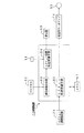
ところで、前記加熱シリンダ11の後端(図3における右端)は前方射出サポート31に取り付けられ、該前方射出サポート31と所定の距離を置いて後方射出サポート32が配設される。そして、前記前方射出サポート31と後方射出サポート32との間にガイドバー33が架設され、該ガイドバー33に沿ってプレッシャプレート34が進退(図3における左右方向に移動)自在に配設される。なお、前記前方射出サポート31及び後方射出サポート32は、図示されないボルトによって図示されないスライドベースに固定される。
【0022】
また、前記スクリュー12の後端にドライブシャフト35が連結され、該ドライブシャフト35は、ベアリング36、37によってプレッシャプレート34に対して回転自在に支持される。そして、スクリュー12を回転させるために、第1の駆動手段として電動の計量用モータ41が配設され、該計量用モータ41とドライブシャフト35との間に、プーリ42、43及びタイミングベルト44から成る第1の回転伝動手段が配設される。したがって、前記計量用モータ41を駆動することによって、スクリュー12を正方向又は逆方向に回転させることができる。なお、本実施の形態においては、前記第1の駆動手段として電動の計量用モータ41を使用しているが、該電動の計量用モータ41に代えて油圧のモータを使用することもできる。
【0023】
また、前記プレッシャプレート34より後方(図3における右方)に、互いに螺合させられたボールねじ軸45及びボールナット46から成るボールねじ47が配設され、該ボールねじ47によって回転運動を直線運動に変換する運動方向変換手段が構成される。そして、前記ボールねじ軸45はベアリング48によって後方射出サポート32に対して回転自在に支持され、前記ボールナット46は、プレート51、及び射出力fを検出する荷重検出手段及び射出力検出手段としてのロードセル52を介してプレッシャプレート34に固定される。さらに、スクリュー12を進退させるために、第2の駆動手段としての射出用モータ53が配設され、該射出用モータ53とボールねじ軸45との間に、プーリ54、55及びタイミングベルト56から成る第2の回転伝動手段が配設される。したがって、前記射出用モータ53を駆動し、ボールねじ軸45を回転させることによってボールナット46及びプレッシャプレート34を移動させ、スクリュー12を前進(図3における左方に移動)又は後退(図3における右方に移動)させることができる。なお、本実施の形態においては、前記第2の駆動手段として射出用モータ53を使用しているが、該射出用モータ53に代えて射出用シリンダを使用して、前記プレート51を移動させるようにすることもできる。
【0024】
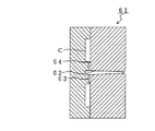
ところで、前記射出ノズル13から射出され、金型装置61内に進入した樹脂は、スプルー62及びランナ63を通過した後、ゲート64を通過して前記キャビティ空間Cに進入するが、樹脂には粘性があり、ゲート64の断面積はランナ63の断面積より小さく、通路が絞られているので、樹脂の先端がゲート64に到達すると、ゲート64より上流側の樹脂の圧力、すなわち、射出圧力が高くなる。成形材料として非晶性の樹脂が使用される場合、前記ゲート64として、サイドゲート、ピンゲート等が使用される場合等においては、射出圧力が一層高くなる。
【0025】
これに伴って、ゲート64より上流側において樹脂が発熱し、樹脂の温度が高くなる。その結果、樹脂の粘性が低くなり、流動性が高くなって前記射出圧力が低くなる。そして、樹脂の先端がゲート64を通過してキャビティ空間C内に進入すると、再び樹脂に加わる抵抗が大きくなり、射出圧力は次第に高くなる。
【0026】
そこで、前記ロードセル52によって、前記射出圧力に対応して変化する射出力fが検出され、射出力fの変化に基づいてゲート通過時スクリュー位置が決定されるようになっている。
【0027】
次に、ゲート通過時スクリュー位置を決定するための制御回路について説明する。
【0028】
図1は本発明の第1の実施の形態における制御回路のブロック図、図5は本発明の第1の実施の形態における制御回路の動作を示すタイムチャートである。
【0029】
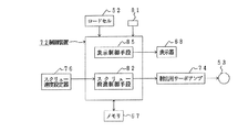
図において、52は射出力fを検出するロードセル、53は射出用モータ、67は記憶手段としてのメモリ、68はディスプレイ等の表示器、72は制御装置、74は射出用サーボアンプ、76はスクリュー速度設定器、81はスクリュー位置を検出するスクリュー位置検出手段としてのスクリュー位置検出器であり、前記制御装置72は、スクリュー前進制御手段82、変化率算出手段83及びスクリュー位置決定制御手段84を備える。
次に、前記構成の制御回路の動作について説明する。
【0030】
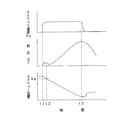
タイミングt1で前記スクリュー前進制御手段82は、速度制御を開始し、前記射出用モータ53を正方向に駆動してスクリュー12を所定のスクリュー速度Vsで所定の距離だけ前進させ、前記スクリューヘッド27の前方に蓄えられた樹脂を射出ノズル13から射出する。
【0031】
この場合、スクリュー速度Vsはあらかじめ設定される。そのために、前記スクリュー速度設定器76は、スクリュー速度指令を発生させ、該スクリュー速度指令をスクリュー前進制御手段82に送る。該スクリュー前進制御手段82は、スクリュー速度指令を受けると、該スクリュー速度指令に対応させて射出用モータ回転速度指令を発生させ、該射出用モータ回転速度指令と、図示されない射出用モータ回転速度センサによって検出された射出用モータ回転速度との偏差を算出し、該偏差を電流指令II として射出用サーボアンプ74に送り、射出用モータ53を駆動する。これにより、スクリュー速度Vsは急速に立ち上がり、ロードセル52によって検出される射出力fが次第に高くなる。
【0032】
この間、前記変化率算出手段83は、ロードセル52によって検出された射出力fを読み込み、該射出力fの変化率Δfを算出し、前記スクリュー位置決定制御手段84は、前記変化率Δfを読み込み、該変化率Δfが正の値から負の値に変化したかどうかを判断する。そして、前記変化率Δfが正の値から負の値に変化した場合、前記スクリュー位置決定制御手段84は、変化率Δfが正の値から負の値に変化したタイミングt2で、スクリュー位置検出器81によって検出されたスクリュー位置を読み込み、該スクリュー位置をゲート通過時スクリュー位置Sgとして決定する。
【0033】
なお、本実施の形態においては、射出力fの変化を取得するために、射出力fの変化率Δfを算出するようにしているが、射出力fの変化量を算出することもできる。また、射出力fが変化したかどうかを判断するために、変化率Δfが正の値から負の値に変化したかどうかを判断するようにしているが、変化率Δfが所定の負の値を採るようになったかどうかを判断したり、変化量が閾(しきい)値を超えたかどうかを判断したりすることもできる。
【0034】
そして、前記制御装置72は、ゲート通過時スクリュー位置Sgを前記表示器68に送る。該表示器68は、ゲート通過時スクリュー位置Sgが送られてくると、ゲート通過時スクリュー位置Sgを画面に表示する。
【0035】
続いて、樹脂の先端がゲート64(図4)を通過してキャビティ空間C内に進入すると、再び樹脂に加わる抵抗が大きくなり、射出圧力は次第に高くなり、それに伴って射出力fも大きくなる。
【0036】
そして、ロードセル52によって検出された射出力fがタイミングt3で所定の値になると、前記制御装置72の図示されない保圧制御手段は、速度制御から圧力制御に切り換え、保圧を行う。このとき、制御装置72の図示されない充填完了位置決定制御手段は、スクリュー位置検出器81からスクリュー位置を読み込み、該スクリュー位置を充填完了位置として決定する。なお、該充填完了位置は、樹脂がキャビティ空間Cに十分に充填されるように、また、成形品にバリが発生しないように設定される。
【0037】
このように、前記射出力fの変化に基づいてゲート通過時スクリュー位置Sgが決定されるので、充填量を変更してゲート通過時スクリュー位置Sgを知るための射出を繰り返す必要がなくなる。したがって、ゲート通過時スクリュー位置Sgを決定するための作業を簡素化することができる。
【0038】
また、射出力fの変化に基づいてゲート通過時スクリュー位置Sgが決定されるので、ゲート通過時スクリュー位置Sgの精度を高くすることができる。したがって、樹脂の先端がゲート64に到達するまでに必要なスクリュー速度Vs、及び樹脂の先端がゲート64を通過した後の、キャビティ空間Cへの樹脂の充填に必要なスクリュー速度Vsを確実に設定することができる。その結果、スクリュー速度設定器76において、射出工程におけるスクリュー速度Vsの最適なパターンを設定することができる。
【0039】
本実施の形態においては、前記スクリュー位置決定制御手段84が、変化率算出手段83によって算出された変化率Δfに基づいてゲート通過時スクリュー位置Sgを決定するようになっているが、スクリュー12の前進を開始してからの射出力fのプロファイルに基づいて、射出成形機の操作者がゲート通過時スクリュー位置Sgを決定することもできる。
【0040】
次に、本発明の第2の実施の形態について説明する。なお、第1の実施の形態と同じ構造を有するものについては、同じ符号を付与することによってその説明を省略する。
【0041】
図6は本発明の第2の実施の形態における制御回路のブロック図である。
【0042】
この場合、制御装置72は、荷重検出手段及び射出力検出手段としてのロードセル52によって検出された射出力f、及びスクリュー位置検出手段としてのスクリュー位置検出器81によって検出されたスクリュー位置を読み込み、スクリュー12(図2)の前進が開始されてから充填完了位置に到達するまでの前記射出力fを、スクリュー位置と対応させて記憶手段としてのメモリ67に、プロファイルとして記録する。そして、前記制御装置72の表示制御手段85は、メモリ67からプロファイルを読み出し、該プロファイルを表示器68に送る。表示器68はプロファイルを画面に表示する。
【0043】
したがって、操作者は、表示されたプロファイルに基づいてゲート通過時スクリュー位置Sgを決定する。
【0044】
なお、本発明は前記実施の形態に限定されるものではなく、本発明の趣旨に基づいて種々変形させることが可能であり、それらを本発明の範囲から排除するものではない。
【0045】
【発明の効果】
以上詳細に説明したように、本発明によれば、射出成形機の位置検出装置においては、スクリューと、該スクリューを進退させるための駆動手段と、該駆動手段を駆動してスクリューを前進させるスクリュー前進制御手段と、スクリュー位置を検出するスクリュー位置検出手段と、前記スクリューの前進に伴って発生する射出力を検出する射出力検出手段と、前記射出力の変化率が正の値から負の値に変化したときのスクリュー位置に基づいてゲート通過時スクリュー位置を決定するスクリュー位置決定制御手段とを有する。
【0046】
この場合、前記射出力の変化率が正の値から負の値に変化したときのスクリュー位置に基づいてゲート通過時スクリュー位置が決定されるので、充填量を変更して射出を繰り返す必要がなくなる。したがって、ゲート通過時スクリュー位置を決定するための作業を簡素化することができる。
【0047】
また、射出力の変化率が正の値から負の値に変化したときのスクリュー位置に基づいてゲート通過時スクリュー位置が決定されるので、ゲート通過時スクリュー位置の精度を高くすることができる。したがって、樹脂の先端がゲートに到達するまでに必要なスクリュー速度、及び樹脂の先端がゲートを通過した後の、キャビティ空間への樹脂の充填に必要なスクリュー速度を確実に設定することができる。その結果、スクリュー速度設定器において、射出工程におけるスクリュー速度の最適なパターンを設定することができる。
【図面の簡単な説明】
【図1】本発明の第1の実施の形態における制御回路のブロック図である。
【図2】本発明の第1の実施の形態における射出装置の要部拡大図である。
【図3】本発明の第1の実施の形態における射出装置の概念図である。
【図4】本発明の第1の実施の形態における金型装置の断面図である。
【図5】本発明の第1の実施の形態における制御回路の動作を示すタイムチャートである。
【図6】本発明の第2の実施の形態における制御回路のブロック図である。
【符号の説明】
12 スクリュー
52 ロードセル
53 射出用モータ
81 スクリュー位置検出器
82 スクリュー前進制御手段
84 スクリュー位置決定制御手段[0001]
BACKGROUND OF THE INVENTION
The present invention relates to a position detection device and a position detection method for an injection molding machine.
[0002]
[Prior art]
Conventionally, in an injection molding machine, a screw is rotatably disposed in a heating cylinder of an injection device and can be moved forward and backward, and the screw can be rotated or moved forward and backward by driving a driving means. It can be done. When the screw is rotated during the metering step, the resin supplied from the hopper into the heating cylinder is heated, melted, advanced, and stored in front of the screw head. Further, during the injection process, the screw is advanced, and the resin stored in front of the screw head is injected from the injection nozzle and filled into the cavity space of the mold apparatus. Subsequently, the molded product can be molded by cooling and solidifying the resin filled in the cavity space.
[0003]
By the way, the resin injected from the injection nozzle and entering the mold apparatus passes through the sprue and the runner, then passes through the gate and enters the cavity space, but before and after passing through the gate, the resin The liquidity is very different. Therefore, it is preferable to change the injection speed (filling amount of resin into the cavity space per unit time) in accordance with the change in fluidity. Therefore, it is necessary to determine the position of the screw when the resin passes through the gate, that is, the screw position as the screw position when passing through the gate.
[0004]
Therefore, the screw is moved forward while speed control is performed, the filling completion position (screw position when filling of the resin into the cavity space is completed) is changed, the molded product is molded, and the resin flow stops near the gate. The filling completion position when such a short shot molded product is obtained is determined as the screw position when passing through the gate. Specifically, after the weighing process is completed, a small amount of resin is injected, and the resin solidified in the sprue and the runner is checked. The injection is repeated while increasing the filling amount until the resin reaches the gate, and the screw position when reaching the gate is set as the screw position when passing through the gate.
[0005]
[Problems to be solved by the invention]
However, in the conventional injection molding machine, since it is necessary to repeat injection by changing the filling amount in order to know the position of the screw when passing through the gate, the work for determining the position of the screw when passing through the gate is troublesome.
[0006]
The present invention provides a position detection device and a position detection method for an injection molding machine that can solve the problems of the conventional injection molding machine and simplify the work for determining the screw position when passing through the gate. For the purpose.
[0007]
[Means for Solving the Problems]
For this purpose, in the position detection apparatus for an injection molding machine of the present invention, a screw, a drive means for advancing and retracting the screw, a screw advance control means for driving the drive means to advance the screw, and a screw position. A screw position detecting means for detecting, a shot power detecting means for detecting a shot power generated as the screw advances, and a screw position when the rate of change of the shot power changes from a positive value to a negative value. And screw position determination control means for determining the screw position when passing through the gate.
[0010]
In the position detection method of the injection molding machine according to the present invention, the drive means is driven to advance the screw, the screw position is detected, the fire output generated as the screw advances, and the change in the fire output is detected. The screw position when passing through the gate is determined based on the screw position when the rate changes from a positive value to a negative value.
[0011]
DETAILED DESCRIPTION OF THE INVENTION
Hereinafter, embodiments of the present invention will be described in detail with reference to the drawings.
[0012]
2 is an enlarged view of the main part of the injection apparatus according to the first embodiment of the present invention, FIG. 3 is a conceptual diagram of the injection apparatus according to the first embodiment of the present invention, and FIG. 4 is the first embodiment of the present invention. It is sectional drawing of the metal mold apparatus in the form of.
[0013]
In the figure, 11 is a heating cylinder as a cylinder member, 12 is a screw as an injection member disposed so as to be rotatable and movable back and forth (movable in the left-right direction in FIG. 2) in the heating cylinder 11, An injection nozzle formed at the front end (left end in FIG. 2) of the
[0014]
The
[0015]
When the
[0016]
By the way, if the roughness of the outer peripheral surface of the
[0017]
When the
[0018]
For this purpose, the
[0019]
Further, the
[0020]
On the other hand, holes 29a extending in the axial direction corresponding to the
[0021]
Incidentally, the rear end (the right end in FIG. 3) of the heating cylinder 11 is attached to the
[0022]
Further, a
[0023]
Further, a
[0024]
By the way, the resin injected from the
[0025]
Along with this, the resin generates heat on the upstream side of the gate 64, and the temperature of the resin increases. As a result, the viscosity of the resin is lowered, the fluidity is increased, and the injection pressure is lowered. When the tip of the resin passes through the gate 64 and enters the cavity space C, the resistance applied to the resin again increases and the injection pressure gradually increases.
[0026]
Therefore, the
[0027]
Next, a control circuit for determining the screw position when passing through the gate will be described.
[0028]
FIG. 1 is a block diagram of a control circuit according to the first embodiment of the present invention, and FIG. 5 is a time chart showing the operation of the control circuit according to the first embodiment of the present invention.
[0029]
In the figure, 52 is a load cell for detecting the shooting power f, 53 is a motor for injection, 67 is a memory as storage means, 68 is a display such as a display, 72 is a control device, 74 is a servo amplifier for injection, and 76 is a screw. A speed setting device 81 is a screw position detector as screw position detecting means for detecting a screw position, and the control device 72 includes a screw advance control means 82, a change rate calculation means 83, and a screw position determination control means 84. .
Next, the operation of the control circuit having the above configuration will be described.
[0030]
At timing t1, the screw advance control means 82 starts speed control, drives the
[0031]
In this case, the screw speed Vs is set in advance. For this purpose, the
[0032]
During this time, the change rate calculation means 83 reads the shooting power f detected by the
[0033]
In the present embodiment, the change rate Δf of the shooting power f is calculated in order to acquire the change of the shooting power f. However, the amount of change of the shooting power f can also be calculated. Further, in order to determine whether or not the shooting power f has changed, it is determined whether or not the rate of change Δf has changed from a positive value to a negative value, but the rate of change Δf has a predetermined negative value. It is also possible to determine whether or not the amount of change has come to be adopted, or to determine whether or not the amount of change exceeds a threshold value.
[0034]
Then, the control device 72 sends the screw position Sg when passing through the gate to the
[0035]
Subsequently, when the tip of the resin passes through the gate 64 (FIG. 4) and enters the cavity space C, the resistance applied to the resin again increases, the injection pressure gradually increases, and the injection power f increases accordingly. .
[0036]
When the shot output f detected by the
[0037]
Thus, since the screw position Sg at the time of passing through the gate is determined based on the change in the shooting power f, it is not necessary to change the filling amount and repeat the injection for determining the screw position Sg at the time of passing through the gate. Therefore, the operation for determining the screw position Sg when passing through the gate can be simplified.
[0038]
Further, since the screw position Sg when passing through the gate is determined based on the change in the radiation output f, the accuracy of the screw position Sg when passing through the gate can be increased. Therefore, the screw speed Vs required until the resin front end reaches the gate 64 and the screw speed Vs required for filling the cavity space C with the resin after the resin front end passes through the gate 64 are reliably set. can do. As a result, the screw
[0039]
In the present embodiment, the screw position determination control unit 84 determines the screw position Sg when passing through the gate based on the change rate Δf calculated by the change rate calculation unit 83. The operator of the injection molding machine can also determine the screw position Sg when passing through the gate based on the profile of the shot power f after starting the forward movement.
[0040]
Next, a second embodiment of the present invention will be described. In addition, about the thing which has the same structure as 1st Embodiment, the description is abbreviate | omitted by providing the same code | symbol.
[0041]
FIG. 6 is a block diagram of a control circuit according to the second embodiment of the present invention.
[0042]
In this case, the control device 72 reads the fire output f detected by the
[0043]
Therefore, the operator determines the screw position Sg when passing through the gate based on the displayed profile.
[0044]
In addition, this invention is not limited to the said embodiment, It can change variously based on the meaning of this invention, and does not exclude them from the scope of the present invention.
[0045]
【The invention's effect】
As described above in detail, according to the present invention, in the position detection device for an injection molding machine, a screw, a driving means for advancing and retracting the screw, and a screw for driving the driving means to advance the screw Advance control means, screw position detection means for detecting the screw position, radiant power detection means for detecting the radiant power generated as the screw advances, and the rate of change of the radiant power is a negative value from a positive value Screw position determination control means for determining the screw position at the time of passing through the gate based on the screw position when changed to.
[0046]
In this case, since the screw position at the time of passing through the gate is determined based on the screw position when the rate of change of the shooting power changes from a positive value to a negative value, there is no need to change the filling amount and repeat the injection. . Therefore, the work for determining the screw position when passing through the gate can be simplified.
[0047]
Further, since the screw position at the time of passing through the gate is determined based on the screw position when the rate of change in the radiant power changes from a positive value to a negative value, the accuracy of the screw position at the time of passing the gate can be increased. Therefore, it is possible to reliably set the screw speed necessary for the front end of the resin to reach the gate and the screw speed required for filling the cavity space with the resin after the front end of the resin passes through the gate. As a result, the screw speed setting device can set an optimum pattern of the screw speed in the injection process.
[Brief description of the drawings]
FIG. 1 is a block diagram of a control circuit according to a first embodiment of the present invention.
FIG. 2 is an enlarged view of a main part of the injection device according to the first embodiment of the present invention.
FIG. 3 is a conceptual diagram of an injection apparatus according to the first embodiment of the present invention.
FIG. 4 is a cross-sectional view of the mold apparatus according to the first embodiment of the present invention.
FIG. 5 is a time chart showing the operation of the control circuit according to the first embodiment of the present invention.
FIG. 6 is a block diagram of a control circuit according to a second embodiment of the present invention.
[Explanation of symbols]
12
Claims (2)
(b)該スクリューを進退させるための駆動手段と、
(c)該駆動手段を駆動してスクリューを前進させるスクリュー前進制御手段と、
(d)スクリュー位置を検出するスクリュー位置検出手段と、
(e)前記スクリューの前進に伴って発生する射出力を検出する射出力検出手段と、
(f)前記射出力の変化率が正の値から負の値に変化したときのスクリュー位置に基づいてゲート通過時スクリュー位置を決定するスクリュー位置決定制御手段とを有することを特徴とする射出成形機の位置検出装置。 (A) a screw;
(B) drive means for moving the screw forward and backward ;
(C) screw advance control means for driving the drive means to advance the screw;
(D) screw position detecting means for detecting the screw position ;
(E) and before Symbol injection force detecting means for detecting an injection force generated in association with the forward movement of the screw,
(F) injection molding characterized by comprising screw position determination control means for determining a screw position at the time of passing through the gate based on a screw position when the rate of change of the radiant power changes from a positive value to a negative value. Machine position detection device .
(b)スクリュー位置を検出し、
(c)前記スクリューの前進に伴って発生する射出力を検出し、
(d)該射出力の変化率が正の値から負の値に変化したときのスクリュー位置に基づいてゲート通過時スクリュー位置を決定することを特徴とする射出成形機の位置検出方法。(A) drives the drive motion means to advance the screw, the
(B) detecting the screw position;
(C) detecting a radiant power generated as the screw advances,
(D) A position detection method for an injection molding machine, wherein a screw position at the time of passing a gate is determined based on a screw position when the rate of change of the radiant power changes from a positive value to a negative value .
Priority Applications (1)
| Application Number | Priority Date | Filing Date | Title |
|---|---|---|---|
| JP2000388150A JP4208043B2 (en) | 2000-12-21 | 2000-12-21 | Position detection apparatus and position detection method for injection molding machine |
Applications Claiming Priority (1)
| Application Number | Priority Date | Filing Date | Title |
|---|---|---|---|
| JP2000388150A JP4208043B2 (en) | 2000-12-21 | 2000-12-21 | Position detection apparatus and position detection method for injection molding machine |
Publications (2)
| Publication Number | Publication Date |
|---|---|
| JP2002187182A JP2002187182A (en) | 2002-07-02 |
| JP4208043B2 true JP4208043B2 (en) | 2009-01-14 |
Family
ID=18854942
Family Applications (1)
| Application Number | Title | Priority Date | Filing Date |
|---|---|---|---|
| JP2000388150A Expired - Fee Related JP4208043B2 (en) | 2000-12-21 | 2000-12-21 | Position detection apparatus and position detection method for injection molding machine |
Country Status (1)
| Country | Link |
|---|---|
| JP (1) | JP4208043B2 (en) |
Families Citing this family (1)
| Publication number | Priority date | Publication date | Assignee | Title |
|---|---|---|---|---|
| JP6077427B2 (en) * | 2013-09-27 | 2017-02-08 | ファナック株式会社 | Control device and control method for injection molding machine |
-
2000
- 2000-12-21 JP JP2000388150A patent/JP4208043B2/en not_active Expired - Fee Related
Also Published As
| Publication number | Publication date |
|---|---|
| JP2002187182A (en) | 2002-07-02 |
Similar Documents
| Publication | Publication Date | Title |
|---|---|---|
| JP3649714B2 (en) | Control device for injection molding machine | |
| US6371748B1 (en) | Back pressure control for an injection molding machine | |
| EP1163993B1 (en) | Injection molding machine and method for controlling screw position in the same | |
| JP5351307B1 (en) | Pressure control device for injection molding machine | |
| JP3434243B2 (en) | Injection device pressure sensor zero point adjustment method | |
| JP3336296B2 (en) | Injection device and control method thereof | |
| JP4208043B2 (en) | Position detection apparatus and position detection method for injection molding machine | |
| JP2013199102A (en) | Injection molding machine | |
| JP3173359B2 (en) | Operation method for screw prepra injection device | |
| JP2000167875A (en) | Nozzle touch off method for injection molding machine and mechanism using this method | |
| JP3337205B2 (en) | Injection device and control method thereof | |
| JP3439152B2 (en) | Injection device and control method thereof | |
| JP3314053B2 (en) | Injection equipment | |
| JP3848137B2 (en) | Injection control device | |
| JP5052246B2 (en) | Injection molding machine | |
| JP3314054B2 (en) | Injection device and control method thereof | |
| JP3321437B2 (en) | Injection device and control method thereof | |
| JP3905319B2 (en) | Injection control device | |
| JP2548324B2 (en) | Injection molding machine plasticization control method | |
| JP5226191B2 (en) | Molding machine and control method thereof | |
| JP3336301B2 (en) | Injection device and control method thereof | |
| JP2001353762A (en) | Injecting unit | |
| JP2002248663A (en) | Method and apparatus for controlling injection | |
| JP3301742B2 (en) | Injection equipment | |
| JP3607602B2 (en) | Injection device and control method thereof |
Legal Events
| Date | Code | Title | Description |
|---|---|---|---|
| A977 | Report on retrieval |
Free format text: JAPANESE INTERMEDIATE CODE: A971007 Effective date: 20040202 |
|
| A131 | Notification of reasons for refusal |
Free format text: JAPANESE INTERMEDIATE CODE: A131 Effective date: 20040210 |
|
| A521 | Written amendment |
Free format text: JAPANESE INTERMEDIATE CODE: A523 Effective date: 20040412 |
|
| A02 | Decision of refusal |
Free format text: JAPANESE INTERMEDIATE CODE: A02 Effective date: 20060328 |
|
| A521 | Written amendment |
Free format text: JAPANESE INTERMEDIATE CODE: A523 Effective date: 20060529 |
|
| A911 | Transfer of reconsideration by examiner before appeal (zenchi) |
Free format text: JAPANESE INTERMEDIATE CODE: A911 Effective date: 20060622 |
|
| A912 | Removal of reconsideration by examiner before appeal (zenchi) |
Free format text: JAPANESE INTERMEDIATE CODE: A912 Effective date: 20061006 |
|
| A01 | Written decision to grant a patent or to grant a registration (utility model) |
Free format text: JAPANESE INTERMEDIATE CODE: A01 |
|
| A61 | First payment of annual fees (during grant procedure) |
Free format text: JAPANESE INTERMEDIATE CODE: A61 Effective date: 20081014 |
|
| R150 | Certificate of patent or registration of utility model |
Free format text: JAPANESE INTERMEDIATE CODE: R150 |
|
| FPAY | Renewal fee payment (event date is renewal date of database) |
Free format text: PAYMENT UNTIL: 20111031 Year of fee payment: 3 |
|
| FPAY | Renewal fee payment (event date is renewal date of database) |
Free format text: PAYMENT UNTIL: 20121031 Year of fee payment: 4 |
|
| FPAY | Renewal fee payment (event date is renewal date of database) |
Free format text: PAYMENT UNTIL: 20131031 Year of fee payment: 5 |
|
| LAPS | Cancellation because of no payment of annual fees |