JP4206183B2 - Valve operating device for internal combustion engine - Google Patents
Valve operating device for internal combustion engine Download PDFInfo
- Publication number
- JP4206183B2 JP4206183B2 JP2000006266A JP2000006266A JP4206183B2 JP 4206183 B2 JP4206183 B2 JP 4206183B2 JP 2000006266 A JP2000006266 A JP 2000006266A JP 2000006266 A JP2000006266 A JP 2000006266A JP 4206183 B2 JP4206183 B2 JP 4206183B2
- Authority
- JP
- Japan
- Prior art keywords
- roller shaft
- rocker arm
- roller
- support wall
- support
- Prior art date
- Legal status (The legal status is an assumption and is not a legal conclusion. Google has not performed a legal analysis and makes no representation as to the accuracy of the status listed.)
- Expired - Fee Related
Links
Images


Description
【0001】
【発明の属する技術分野】
本発明は、相互に隣接したロッカアームの一方に、カムシャフトに設けられるカムにころがり接触するローラを相互間に配置する第1および第2支持壁が第2支持壁を他方のロッカアーム側に配置して設けられ、両ロッカアームを連動させる連動位置ならびに前記一方のロッカアームから離脱して前記連動を解除する連動解除位置間での移動が可能な切換ピンを前記連動位置への移動に応じて摺動自在に嵌合させる円筒状のローラ軸が、前記ローラを回転自在に支承して第1および第2支持壁間に架設される内燃機関の動弁装置に関する。
【0002】
【従来の技術】
従来、かかる動弁装置は、たとえば特開平11−13440号公報等により既に知られている。
【0003】
【発明が解決しようとする課題】
上記従来の動弁装置では、ローラ軸をロッカアームに固定するために、ロッカアームに設けられた嵌合孔に嵌合されたローラ軸の外面に係合する固定ピンをロッカアームに挿入、固定するようにしており、ローラ軸の固定のために固定ピンが必要となって部品点数が増えるとともに固定ピンの挿入、固定作業を行なう必要があって組付作業工数が増え、しかも固定ピンを挿入するための挿入孔をロッカアームに設けるとともに固定ピンを係合するための溝をローラ軸の外面に設ける必要があるので加工工数も増大する。
【0004】
このような部品点数の増大および加工工数の増大を避けるために、ローラ軸の両端部を第1および第2支持壁にかしめ固定することも考えられるが、ローラ軸のかしめ変形が大になると、ローラ軸内に挿脱される切換ピンの作動が不円滑となり、相互に隣接したロッカアームの連結および連結解除が不円滑となる可能性がある。
【0005】
本発明は、かかる事情に鑑みてなされたものであり、ローラを支持するとともに切換ピンを案内するローラ軸を、部品点数の増大および加工工数の増大を回避しつつ、ロッカアームに容易に固定し得るようにし、しかも切換ピンによる隣接ロッカアームの連結および連結解除を円滑とした内燃機関の動弁装置を提供することを目的とする。
【0006】
【課題を解決するための手段】
上記目的を達成するために、請求項1記載の発明は、相互に隣接したロッカアームの一方に、カムシャフトに設けられるカムにころがり接触するローラを相互間に配置する第1および第2支持壁が第2支持壁を他方のロッカアーム側に配置して設けられ、この第1および第2支持壁間に前記ローラを回転自在に支承する円筒状のローラ軸が架設され、前記他方のロッカアームには切換ピンが摺動可能に嵌合され、その切換ピンは、該ピンの一部を前記ローラ軸内に嵌入させて両ロッカアームを連動させる連動位置と、ローラ軸内よりピン全体を退出させて前記連動を解除する連動解除位置との間を摺動可能である内燃機関の動弁装置において、前記ローラ軸が、第1支持壁にかしめ固定されるとともに第2支持壁に圧入され、前記ローラ軸のかしめ固定による変形量が圧入による変形量よりも大きいことを特徴とする。
【0007】
このような請求項1記載の発明の構成によれば、ローラ軸が第1支持壁にかしめ固定されるとともに第2支持壁に圧入されるので、ローラ軸の固定のために固定ピンを必要とした従来のものと比べると、部品点数の増大および加工工数の増大を回避しつつ、ローラ軸をロッカアームに容易に固定することができる。しかもかしめ固定によるローラ軸の変形量は圧入による変形量よりも大きいので、第2支持壁にローラ軸を圧入することにより連動位置への切換ピンの移動時に該切換ピンを受入れる側すなわち第2支持壁側のローラ軸の端部の変形を小さく抑えて、切換ピンのローラ軸への嵌入を円滑にして隣接ロッカアームの切換ピンによる連動および連動解除の切換えを円滑とすることができる。また第1支持壁側でローラ軸を強固に保持することができるので、第2支持壁側での圧入代も小さく設定することができ、第2支持壁側でのローラ軸の変形量をより一層小さくすることができる。
【0008】
また請求項2記載の発明は、相互に隣接したロッカアームの一方に、カムシャフトに設けられるカムにころがり接触するローラを相互間に配置する第1および第2支持壁が第2支持壁を他方のロッカアーム側に配置して設けられ、両ロッカアームを連動させる連動位置ならびに前記一方のロッカアームから離脱して前記連動を解除する連動解除位置間での移動が可能な切換ピンを前記連動位置への移動に応じて摺動自在に嵌合させる円筒状のローラ軸が、前記ローラを回転自在に支承して第1および第2支持壁間に架設される内燃機関の動弁装置において、前記ローラ軸が第1および第2支持壁にかしめ固定され、第2支持壁側での前記ローラ軸の半径方向内方側へのかしめ変形量が第1支持壁側での前記ローラ軸の半径方向内方側へのかしめ変形量よりも小さく設定される。
【0009】
このような請求項2記載の発明の構成によれば、ローラ軸の固定のために固定ピンを必要とした従来のものと比べると、部品点数の増大および加工工数の増大を回避しつつ、ローラ軸をロッカアームに容易に固定することができる。しかも連動位置への切換ピンの移動時に該切換ピンを受入れる側すなわち第2支持壁側でのローラ軸の端部のかしめによる半径方向内方側への変形を小さく抑え、切換ピンのローラ軸への嵌入を円滑にして隣接ロッカアームの切換ピンによる連動および連動解除の切換えを円滑とすることができるとともに、第1支持壁側でローラ軸を強固に保持することができる。
【0010】
【発明の実施の形態】
以下、本発明の実施の形態を、添付の図面に示した本発明の実施例に基づいて説明する。
【0011】
図1〜図7は本発明の第1実施例を示すものであり、図1は内燃機関の一部縦断面図、図2は図1の2矢視平面図、図3は図1の3−3線矢視拡大図、図4は図3の4−4線断面図、図5は図1の5−5線拡大断面図、図6は図3の6−6線拡大断面図、図7はロッカアームへのローラ軸の固定構造を説明するための断面図である。
【0012】
先ず図1および図2において、この多気筒内燃機関は、シリンダブロック11と、該シリンダブロック11の上部にガスケット12を介して結合されるシリンダヘッド13とを備え、各気筒毎にシリンダブロック11に設けられるシリンダ14にピストン15がそれぞれ摺動可能に嵌合される。またシリンダブロック11、シリンダヘッド13および各ピストン15により、各気筒毎に燃焼室16が形成される。
【0013】
シリンダヘッド13には、燃焼室16の天井面一側に臨む一対の吸気弁口17…と、両吸気弁口17…に共通に連なってシリンダヘッド13の一側面(図1の右側面)に開口する吸気ポート18とが各気筒毎に設けられるとともに、燃焼室16の天井面他側に臨む一対の排気弁口19…と、両排気弁口19…に共通に連なってシリンダヘッド13の他側面(図1の左側面)に開口する排気ポート20とが各気筒毎に設けられる。
【0014】
各吸気弁口17…をそれぞれ開閉可能な吸気弁VI,VIのステム21…はシリンダヘッド13に設けられたガイド筒22…に摺動可能に嵌合され、ガイド筒22…から上方に突出したステム21…の上端部に設けられるリテーナ23,23およびシリンダヘッド13間に、吸気弁VI,VIを上方すなわち閉弁方向に付勢する弁ばね24…が設けられる。また排気弁口19…をそれぞれ開閉可能な排気弁VE,VEのステム25…はシリンダヘッド13に設けられたガイド筒26…に摺動可能に嵌合され、ガイド筒26…から上方に突出したステム25…の上端部に設けられるリテーナ27,27およびシリンダヘッド13間に、排気弁VE,VEを上方すなわち閉弁方向に付勢する弁ばね28…が設けられる。
【0015】
両吸気弁VI,VIは吸気側動弁装置30で開閉駆動され、両排気弁VE,VEは排気側動弁装置31で開閉駆動されるものであり、両動弁装置30,31間には、燃焼室16の中央部に臨んでシリンダヘッド13に取付けられる点火プラグ32を挿入するためのプラグ挿入筒33が上下に延びるようにして配置され、該プラグ挿入筒33の下端はシリンダヘッド13に取付けられる。
【0016】
吸気側動弁装置30は、一対の吸気弁VI,VIに個別に対応した第1および第2駆動ロッカアーム34,35と、それらの駆動ロッカアーム34,35すなわち前記各吸気弁VI,VIに対して自由となり得る自由ロッカアーム36と、各ロッカアーム34〜36を揺動可能に支承する吸気側ロッカシャフト37と、該ロッカシャフト37と平行な軸線まわりに回転可能な吸気側カムシャフト38とを備える。
【0017】
排気側動弁装置31は、一対の排気弁VE,VEに個別に対応した第1および第2駆動ロッカアーム39,40と、それらの駆動ロッカアーム39,40すなわち前記各排気弁VE,VEに対して自由となり得る自由ロッカアーム41と、各ロッカアーム39〜41を揺動可能に支承する排気側ロッカシャフト42と、該ロッカシャフト42と平行な軸線まわりに回転可能な排気側カムシャフト43とを備える。
【0018】
吸気側および排気側ロッカシャフト37,42は、各気筒間でシリンダヘッド13に設けられたホルダ壁44,44…で固定的に支持される。また吸気側および排気側カムシャフト38,43は、図示しないクランクシャフトに1/2の減速比で連動、連結されるものであり、前記ホルダ壁44,44…と、それらのホルダ壁44,44…の上端に締結されるカムホルダ45,45…とで回転自在に支承される。
【0019】
ところで吸気側および排気側動弁装置30,31は、基本的には同一の構成を有するものであり、以下、吸気側動弁装置の構成および作用について詳細に説明するが、排気側動弁装置31についての説明を省略する。
【0020】
吸気側カムシャフト38には、高速用カム47と、両吸気弁VI,VIにそれぞれ対応して高速用カム47の両側に配置される低速用カム46,46とが設けられる。
【0021】
図3において、第1駆動ロッカアーム34、第2駆動ロッカアーム35および自由ロッカアーム36は、軽量化を図るためにたとえばアルミニウム合金で形成されるとともに表面にアルマイト処理が施されるものであり、第1および第2駆動ロッカアーム34,35で自由ロッカアーム36を挟むようにして相互に隣接配置され、吸気側ロッカシャフト37で共通にかつ揺動可能に支持される。
【0022】
第1および第2駆動ロッカアーム34,35および自由ロッカアーム36は、吸気側ロッカシャフト37で揺動可能に支承される円筒状の揺動支持部34a,35a,36aを基端に備えるとともに、吸気側ロッカシャフト37の軸線に沿う方向に間隔をあけた位置で前記揺動支持部34a,35a,36aから延設されて相互に対向する第1および第2支持壁34b,34c;35b,35c;36b,36cを備えており、第1および第2駆動ロッカアーム34,35における第1および第2支持壁34b,34c;35b,35cの先端は連結部34d,35dで相互に連結される。
【0023】
図4を併せて参照して、第1および第2駆動ロッカアーム34,35の先端における前記連結部34d,35dには、両吸気弁VI,VIにおけるステム21…の上端に当接するタペットねじ48,48が進退自在に螺合される。
【0024】
また自由ロッカアーム36の揺動支持部36aにおいてプラグ挿入筒33に対応する部分には、該プラグ挿入筒33を自由ロッカアーム36側に近接せしめることを可能とするための円弧状の切欠き49が、プラグ挿入筒33と反対側に凹むようにして設けられる。
【0025】
図5および図6をさらに併せて参照して、第1駆動ロッカアーム34の上面の両支持壁34b,34c間には凹部50が形成され、第2駆動ロッカアーム35の上面の両支持壁35b,35c間には凹部51が形成され、自由ロッカアーム36の両支持壁36b,36c間には凹部52が形成される。しかも第1および第2駆動ロッカアーム34,35における前記凹部50,51の中央部には上下に開口した開口部53,54が設けられ、自由ロッカアーム36における凹部52の中央部には、吸気側ロッカシャフト37と反対側および上方に開口した開口部55が設けられる。
【0026】
第1および第2駆動ロッカアーム34,35には、低速用カム46,46にころがり接触するローラ56,57が前記開口部53,54に配置されるようにして回転自在に支持され、自由ロッカアーム36には、高速用カム47にころがり接触するローラ58が前記開口部55に配置されるようにして回転自在に支承される。而して前記各ロッカアーム34,35,36の凹部50,51,52にはオイルを溜めることが可能であり、各凹部50,51,52はオイルを各ローラ56,57,58側に案内し得るように形成され、凹部50,51,52から各ローラ56〜58にオイルを滑らかに導く通路が設けられることで各ローラ56〜58の潤滑を効果的に行なうことができる。
【0027】
しかも吸気側ロッカシャフト37の軸線に沿う方向での低速用カム46,46の幅は、第1および第2駆動ロッカアーム34,35における第1および第2支持壁34b,34c;35b,35c間の間隔以下に設定され、吸気側ロッカシャフト37の軸線に沿う方向での高速用カム47の幅は、自由ロッカアーム36における第1および第2支持壁36b,36c間の間隔以下に設定されており、低速用カム46,46の下部は、ローラ56,57との接触点を第1および第2支持壁34b,34c;35b,35cの上端よりも下方にして凹部50,51に収容され、高速用カム47の下部はローラ58との接触点を第1および第2支持壁36b,36cの上端よりも下方にして凹部52に収容される。
【0028】
第1駆動ロッカアーム34の第1および第2支持壁34b,34cには、吸気側ロッカシャフト37の軸線と平行な軸線を有する貫通孔59,60が同軸に設けられ、第2駆動ロッカアーム35の第1支持壁35bには吸気側ロッカシャフト37の軸線と平行な軸線を有する貫通孔61が設けられ、第2支持壁35cには、自由ロッカアーム36とは反対側を閉じた有底穴62が前記貫通孔61と同軸に設けられる。さらに自由ロッカアーム36の第1および第2支持壁36b,36cには、吸気側ロッカシャフト37の軸線と平行な軸線を有する貫通孔63,64が同軸に設けられる。
【0029】
第1駆動ロッカアーム34には、第1駆動ロッカアーム34よりも硬質の材料、すなわち第1駆動ロッカアーム34がアルミニウム合金から成るものであるときにはたとえば鉄系の材料から成る円筒状のローラ軸65が、両貫通孔59,60への圧入により固定され、第2駆動ロッカアーム35には、第2駆動ロッカアーム34よりも硬質の材料、すなわち第2駆動ロッカアーム35がアルミニウム合金から成るものであるときにはたとえば鉄系の材料から成る円筒状のローラ軸66が、貫通孔61および有底穴62への圧入により固定される。
【0030】
自由ロッカアーム36には、自由ロッカアーム36よりも硬質の材料、すなわち自由ロッカアーム36がアルミニウム合金から成るものであるときにはたとえば鉄系の材料から成る円筒状のローラ軸67が固定される。
【0031】
前記各ローラ軸65,66,67は、内径を同一として円筒状に形成されるものであり、各ローラ軸65,66,67および前記各ローラ56,57,58間には、ニードルベアリング68,69,70がそれぞれ介装される。
【0032】
図7において、自由ロッカアーム36の第1支持壁36bに設けられている貫通孔63の外端縁には、テーパ状の面取り部63aが設けられる。またローラ軸67は、第1支持壁36bにかしめ固定されるとともに第2支持壁36cに圧入されるものであり、貫通孔63に挿通されたローラ軸67の一端面をかしめて前記面取り部63aに係合することでローラ軸67の一端が自由ロッカアーム36の第1支持壁36bに固定されるとともに、ローラ軸67の他端が前記貫通孔64に圧入される。
【0033】
図6に注目して、自由ロッカアーム36の下方でシリンダヘッド13には、自由ロッカアーム36のローラ58を高速用カム47にころがり接触せしめる方向のばね力を自由ロッカアーム36に作用せしめるロストモーション機構72が設けられ、該ロストモーション機構72は、上部を開放してシリンダヘッド13に設けられる有底の摺動孔73に収納されて該摺動孔73の下端閉塞部で一端を受けられるばね74と、該ばね74の他端に連結されるリフタ75とで構成される。
【0034】
一方、自由ロッカアーム36は、ロストモーション機構72からのばね力を受けるべくリフタ75の上端に接触する受け部76を備えるのであるが、該受け部76は、自由ロッカアーム36が備える第1および第2支持壁部36b,36cの先端側下部を連結する連結壁77に、自由ロッカアーム36で支持されるローラ58の軸方向中央部にほぼ対応するようにして設けられる。而して、この実施例では自由ロッカアーム36が比較的軟質であるアルミニウム合金から成るものであるので、前記受け部76は、鉄系材料等の硬質材料から成る部材を連結壁77に固着することで構成されるが、自由ロッカアーム36が硬質材料から成るものである場合には受け部76が連結壁77に一体に形成されるものであってもよい。また前記受け部76には、その内外面間にわたるオイル通路78が設けられる。
【0035】
しかも前記連結壁77は、ローラ58の下方に延びるものであり、該連結壁77の先端およびローラ58間の間隔L1は、連結壁77の中間部およびローラ58間の間隔よりも小さく設定される。すなわちローラ58の下方に延びる連結壁77はローラ58の最下部側に向うにつれてローラ58との間隔を狭めるように形成される。
【0036】
第1駆動ロッカアーム34、第2駆動ロッカアーム35および自由ロッカアーム36間には、各ロッカアーム34〜36を連動させる状態、ならびに各ロッカアーム34〜36の連動を解除する状態を切換える連動切換手段80が設けられるものであり、この連動切換手段80は、相互に隣接した第2駆動ロッカアーム35および自由ロッカアーム36の連動および連動解除を切換可能な第1切換ピン81と、相互に隣接した自由ロッカアーム36および第1駆動ロッカアーム34の連動および連動解除を切換可能な円筒状の第2切換ピン82と、第1切換ピン81とは反対側で第2切換ピン82に接触する規制部材83と、規制部材83を第2切換ピン82側に付勢するコイル状の戻しばね84とを備え、各切換ピン81,82および規制部材83はローラ軸65〜67と同じ硬質材料により形成される。
【0037】
第1切換ピン81は、第2駆動ロッカアーム35のローラ軸66に摺動可能に嵌合されるものであり、ローラ軸66が圧入される有底穴62の閉塞端と第1切換ピン81との間に油圧室85が画成される。吸気側ロッカシャフト37内には、図示しない制御弁を介して油圧源に接続される油路86がたとえば同軸に設けられており、油圧室85に一端を通じさせて第2駆動ロッカアーム35の第2支持壁35cに設けられる連通路87に通じる環状路88が第2駆動ロッカアーム35および吸気側ロッカシャフト37間に設けられ、該環状路88および油路86間を連通する連通孔89が吸気側ロッカシャフト37に設けられる。
【0038】
第2切換ピン82は自由ロッカアーム36のローラ軸67に摺動可能に嵌合され、第1および第2切換ピン81,82は相互に滑ることを可能として接触せしめられる。
【0039】
規制部材83は、有底円筒状に形成されて第1駆動ロッカアーム34のローラ軸65に摺動可能に嵌合されるものであり、この規制部材83の閉塞端が第2切換ピン82に相互に滑ることを可能として接触せしめられる。またローラ軸65の内面には、規制部材83に当接して該規制部材83がローラ軸65から脱落するのを阻止するための止め輪90が装着される。
【0040】
前記ローラ軸65の外端側には、リング状のワッシャ91が挿入されており、このワッシャ91の外面に係合する止め輪92がローラ軸65の内面に嵌着される。而して戻しばね84は、規制部材83およびワッシャ91間に設けられる。
【0041】
このような連動切換手段80において、機関の低速運転域では、油圧室85の油圧は比較的低圧であり、第1および第2切換ピン81,82の接触面は第2駆動ロッカアーム35および自由ロッカアーム36間に対応する位置に在り、第2切換ピン82および規制部材83の接触面は自由ロッカアーム36および第1駆動ロッカアーム34間に対応する位置に在る。したがって各ロッカアーム34,35,36は相対揺動可能な状態に在り、両吸気弁VI,VIが低速用カム46,46に応じたタイミングおよびリフト量で開閉駆動されることになる。
【0042】
機関の高速運転域では、油圧室85に比較的高圧の油圧が作用せしめられ、第1切換ピン81は第2切換ピン82を押圧しながら自由ロッカアーム36のローラ軸67に摺動自在に嵌合し、第2切換ピン82は規制部材83を押圧しながら第1駆動ロッカアーム34のローラ軸65に摺動自在に嵌合する。したがって各ロッカアーム34,35,36は一体的に連結された状態となり、両吸気弁VI,VIは高速用カム47に応じたタイミングおよびリフト量で開閉駆動されることになる。
【0043】
次にこの第1実施例の作用について説明すると、吸気側動弁装置30における各ロッカアーム34,35,36は、吸気側ロッカシャフト37で揺動可能に支承される揺動支持部34a,35a,36aを備えるとともに、各揺動支持部34a,35a,36aから延設される第1および第2支持壁34b,34c;35b,35c;36b,36cをそれぞれ有しており、各ロッカアーム34〜36の上面の両支持壁34b,34c;35b,35c;36b,36c間には凹部50,51,52がそれぞれ形成される。しかも各凹部50〜52の中央部には吸気側カムシャフト38の低速用カム46,46および高速用カム47にころがり接触するローラ56,57,58が配置されており、前記各カム46,46,47の一部は、前記両支持壁34b,34c;35b,35c;36b,36cの上端よりも下方でローラ56,57,58に接触するようにして、前記各凹部50〜52に収容される。
【0044】
したがって吸気側カムシャフト38を各ロッカアーム34〜36に近接させることが可能であり、各ロッカアーム34〜36および吸気側カムシャフト38のレイアウト上の自由度を大として機関全体の小型を図ることができる。また凹部50〜52の両側の支持壁34b,34c;35b,35c;36b,36cが補強リブとしての働きをすることになり、吸気側ロッカシャフト37への揺動支持部34a,35a,36aの支持剛性を高めることができる。しかも各凹部にオイル50〜52にオイルを溜めて各ローラ56〜58を潤滑することも可能となる。
【0045】
ところで、前記各ロッカアーム34〜36のうち吸気弁VI,VIに対して自由となり得る自由ロッカアーム36には、ロストモーション機構72により自由ロッカアーム36に対応する高速用カム47側に向けて押圧するばね力が作用するのであるが、該自由ロッカアーム36の両支持壁36b,36c間が連結壁77で連結され、前記ロストモーション機構72のリフタ75に接触する受け部76が、自由ロッカアーム36で支持されるローラ58の軸方向中央部にほぼ対応して連結壁77に設けられている。
【0046】
したがって、自由ロッカアーム36に高速用カム47から作用する荷重点と、ロストモーション機構72から作用する押圧点とがローラ58の軸線方向で大きくずれてしまうことがなく、自由ロッカアーム36の安定的な揺動支持が可能となる。また連結壁77で第1および第2支持壁36b,36c間を連結するので、両支持壁36b,36c間で回転支持されるローラ58の支持剛性を高めることができる。
【0047】
しかも連結壁77は、ローラ58との間の間隔をローラ58の最下部側に向かうにつれて狭める形状に形成されてローラ58の下方に配置されているので、ローラ58および連結壁77間にオイルを保持することを可能とし、該オイルでローラ58を潤滑することができる。また受け部76には、その内外面間にわたるオイル通路78が設けられており、ローラ58および連結壁77間に保持されたオイルをロストモーション機構72のリフタ75および受け部76の接触部に導くことで該接触部での摩耗低減に寄与することができる。
【0048】
吸気側カムシャフト38の低速用カム46,47および高速用カム47にころがり接触するローラ56,57,58は、各ロッカアーム34,35,36に固定された円筒状のローラ軸65,66,67にニードルベアリング68,69,70を介してそれぞれ回転自在に支承されており、連動切換手段80の第1および第2切換ピン81,82は、連動切換手段80が連動解除状態から連動状態へと作動する際に、自由ロッカアーム36のローラ軸67ならびに第1駆動ロッカアーム34のローラ軸65にそれぞれ摺動自在に嵌合される。すなわち第2駆動ロッカアーム35および自由ロッカアーム36間に跨がる第1切換ピン81で第2駆動ロッカアーム35および自由ロッカアーム36が連結され、自由ロッカアーム36および第2駆動ロッカアーム34間に跨がる第2切換ピン82で自由ロッカアーム36および第2駆動ロッカアーム34が連結される。
【0049】
而してローラ軸65,66,67は、対応のロッカアーム34,35,36よりも硬質の材料により形成されており、ローラ軸65,66は、両駆動ロッカアーム34,35がそれぞれ備える第1および第2支持壁34b,34c;35b,35cに圧入されており、またローラ軸67は、自由ロッカアーム36が備える第1支持壁36bにかしめ固定されるとともに第2支持壁36cに圧入されている。したがってローラ軸65〜67の固定のためにローラ軸65〜67以外の部品を必要とせず、部品点数の増大および加工工数の増大を回避しつつ、ローラ軸65〜67をロッカアーム34〜36に容易に固定することができる。
【0050】
しかもかしめ固定によるローラ軸67の変形量は圧入による変形量よりも大きいので、第2支持壁36cにローラ軸67を圧入することにより連動位置への第1切換ピン81の移動時に該第1切換ピン81を受入れる側すなわち第2支持壁36c側のローラ軸67の端部の変形を小さく抑えて、第1切換ピン81のローラ軸67への嵌入を円滑にして隣接ロッカアーム35,36の第1切換ピン81による連動および連動解除の切換えを円滑とすることができる。また第1支持壁36b側でローラ軸67を強固に保持することができるので、第2支持壁36c側での圧入代も小さく設定することができ、第2支持壁36c側でのローラ軸67の変形量をより一層小さくすることができる。
【0051】
各ロッカアーム34,35,36の配列方向に沿う一端側に配置される第1駆動ロッカアーム34においては、第1駆動ロッカアーム34が備える第1および第2支持壁34b,34cに、ローラ軸65の両端部を圧入するする貫通孔59,60が同軸に設けられており、連動切換手段80の戻しばね84を受けるワッシャ91がローラ軸65に装着されている。
【0052】
したがって、第1支持壁34bに有底穴を穿孔加工しなければならないものと比べると、有底穴の閉塞端側に逃げ加工を施すことが不要となり、第1駆動ロッカアーム34の小型化を可能としつつ第1支持壁34bへの穿孔加工を容易とすることができ、端壁が不要となる分だけ第1駆動ロッカアーム34の重量を低減することができる。しかもこの実施例のように、吸気側ロッカシャフト37およびローラ軸65が平行となるものでは、第1および第2支持壁34b,34cでの吸気側ロッカシャフト37およびローラ軸65の軸線間の間隔を精度よく定めることができる。
【0053】
しかもワッシャ91は、ローラ軸65の内面に嵌着される止め輪92に外面を係合するようにしてローラ軸65に挿入されるので、ワッシャ91のローラ軸65への装着が容易である。またワッシャ91の内径を比較的大きく設定することでローラ軸65内を外部から視認することができ、戻しばね84がローラ軸65内に正しく収容されているか否かを外部から確認することができる。
【0054】
図8は本発明の参考例を示すものであり、上記第1実施例に対応する部分には同一の参照符号を付す。
【0055】
ローラ軸67の両端は、自由ロッカアーム36の第1および第2支持壁36b,36cにかしめ固定されるのであるが、そのかしめ固定にあたって、ローラ軸67は、少なくとも第2駆動ロッカアーム35側の端部を第2支持壁36cから前記第2駆動ロッカアーム35側に突出せしめられる。而して、この参考例では、ローラ軸67が第1および第2支持壁36b,36cの外側面から突出量L2だけ突出する長さを有するように形成されており、両支持壁36b,36cの貫通孔63,64に挿通されて両支持壁36b,36cから突出されたローラ軸67の両端面が、第1および第2支持壁36b,36cの外側面にかしめ係合される。
【0056】
この参考例によれば、上記第1実施例と同様に、ローラ軸67の固定のためにローラ軸67以外の部品を必要とせず、部品点数の増大および加工工数の増大を回避しつつ、ローラ軸67を自由ロッカアーム36に容易に固定することができる。しかもローラ軸67の両支持壁36b,36cから突出した部分がかしめにより変形することになり、ローラ軸67のかしめによって自由ロッカアーム36に作用する負荷を軽減して自由ロッカアーム36の変形を極力防止することができ、またローラ軸67の両端部の半径方向内方側への変形も少なくなるので、第1切換ピン81のローラ軸67への円滑な嵌入が可能となる。それにより第2駆動ロッカアーム35および自由ロッカアーム36の第1切換ピン81による連動および連動解除の切換えを円滑とすることができる。
【0057】
図9は本発明の第2実施例を示すものであり、上記第1実施例に対応する部分には同一の参照符号を付す。
【0058】
第1および第2駆動ロッカアーム34,35にはそれらのロッカアーム34,35よりも硬質の材料から成る円筒状のローラ軸65,66が圧入され、自由ロッカアーム36には、自由ロッカアーム36よりも硬質の材料から成るローラ軸67′がかしめ固定される。しかも各ローラ軸65,66,67′にローラ56′,57′,58′がそれぞれ直接支持される。
【0059】
自由ロッカアーム36にかしめ固定されるローラ軸67′は、その内径を第1および第2駆動ロッカアーム34,35のローラ軸65,66と同一とするが、外径をそれらのローラ軸65,66よりも大径とした肉厚に形成されており、このローラ軸67′が、第2支持壁36c側でのローラ軸67′の半径方向内方側へのかしめ変形量が第1支持壁36b側でのローラ軸67′の半径方向内方側へのかしめ変形量よりも小さくなるようにして、第1および第2支持壁36b,36cにかしめ固定される。この際、この第2実施例では、ローラ軸67′の軸線からの半径方向に沿う距離を同一として該ローラ軸67′の両端のかしめ変形箇所が設定されており、第2支持壁36c側でのローラ軸67′のかしめ変形量が第1支持壁36b側でのかしめ変形量よりも小となるように設定されることにより、第2支持壁36c側でのローラ軸67′の半径方向内方側へのかしめ変形量が第1支持壁36b側でのローラ軸67′の半径方向内方側へのかしめ変形量よりも小さくされる。
【0060】
この第2実施例によれば、第1および第2支持壁36b,36cへのかしめ固定により、ローラ軸67′の固定のためにローラ軸67′以外の部品を必要とせず、部品点数の増大および加工工数の増大を回避しつつ、ローラ軸67′を自由ロッカアーム36に容易に固定することができる。しかも連動位置への第1切換ピン81の移動時に第1切換ピン81を受入れる側すなわち第2支持壁36c側でのローラ軸67′の端部のかしめによる半径方向内方側変形を小さく抑えることができる。したがって第1切換ピン81のローラ軸67′への嵌入を円滑にして第2駆動ロッカアーム35および自由ロッカアーム36の連動および連動解除の切換えを円滑とすることができ、第1支持壁36b側でローラ軸67′を強固に保持することができる。
【0061】
本発明のさらに他の実施例として、第2支持壁36c側でのローラ軸67′のかしめ変形箇所が、第1支持壁36b側でのローラ軸67′のかしめ変形箇所よりも該ローラ軸67′の軸線からの距離が大となる位置に設定され、それらのかしめ変形箇所でのかしめ変形量を同一とすることにより、第2支持壁36c側でのローラ軸67′の半径方向内方側へのかしめ変形量が第1支持壁36b側でのローラ軸67′の半径方向内方側へのかしめ変形量よりも小さくなるようにしてもよい。
【0062】
以上、本発明の実施例及び参考例を説明したが、本発明は上記実施例に限定されるものではなく、特許請求の範囲に記載された本発明を逸脱することなく種々の設計変更を行うことが可能である。
【0063】
【発明の効果】
以上のように請求項1記載の発明によれば、部品点数の増大および加工工数の増大を回避しつつ、ローラ軸をロッカアームに容易に固定することができ、連動位置への切換ピンの移動時に該切換ピンを受入れる側すなわち第2支持壁側のローラ軸の端部の変形を小さく抑えて切換ピンのローラ軸への嵌入を円滑にし、隣接ロッカアームの切換ピンによる連動および連動解除の切換えを円滑とすることができる。また第1支持壁側でローラ軸を強固に保持することができるので、第2支持壁側での圧入代も小さく設定することができ、第2支持壁側でのローラ軸の変形量をより一層小さくすることができる。
【0064】
また請求項2記載の発明によれば、部品点数の増大および加工工数の増大を回避しつつ、ローラ軸をロッカアームに容易に固定することができ、第2支持壁側でのローラ軸の端部のかしめによる半径方向内方側への変形を小さく抑えて切換ピンのローラ軸への嵌入を円滑にし、隣接ロッカアームの切換ピンによる連動および連動解除の切換えを円滑とすることができ、また第1支持壁側でローラ軸を強固に保持することができる。
【図面の簡単な説明】
【図1】内燃機関の一部縦断面図である。
【図2】図1の2矢視平面図である。
【図3】図1の3−3線矢視拡大図である。
【図4】図3の4−4線断面図である。
【図5】図1の5−5線拡大断面図である。
【図6】図3の6−6線拡大断面図である。
【図7】ロッカアームへのローラ軸の固定構造を説明するための断面図である。
【図8】参考例の図7に対応した断面図である。
【図9】第2実施例の図5に対応した断面図である。
【符号の説明】
30・・・吸気側動弁装置
35・・・第2駆動ロッカアーム
36・・・自由ロッカアーム
36b・・・第1支持壁
36c・・・第2支持壁
38・・・吸気側カムシャフト
47・・・高速用カム
58・・・ローラ
67,67′・・・ローラ軸
81・・・切換ピン[0001]
BACKGROUND OF THE INVENTION
In the present invention, a first support wall and a second support wall are disposed on one side of the rocker arms adjacent to each other, and the second support wall is disposed on the other rocker arm side. A switching pin that can be moved between an interlocking position for interlocking the two rocker arms and an interlock release position for releasing the interlocking by releasing from the one rocker arm is slidable according to the movement to the interlocking position. The present invention relates to a valve operating apparatus for an internal combustion engine in which a cylindrical roller shaft to be fitted to the shaft is supported between the first and second support walls by rotatably supporting the roller.
[0002]
[Prior art]
Conventionally, such a valve operating apparatus is already known, for example, from JP-A-11-13440.
[0003]
[Problems to be solved by the invention]
In the above conventional valve gear, in order to fix the roller shaft to the rocker arm, a fixing pin that engages the outer surface of the roller shaft fitted in the fitting hole provided in the rocker arm is inserted and fixed to the rocker arm. In order to fix the roller shaft, the number of parts increases and the number of parts needs to be inserted and fixed. Since it is necessary to provide an insertion hole in the rocker arm and a groove for engaging the fixing pin on the outer surface of the roller shaft, the number of processing steps increases.
[0004]
In order to avoid such an increase in the number of parts and an increase in processing man-hours, it is conceivable to fix both ends of the roller shaft to the first and second support walls, but when the caulking deformation of the roller shaft becomes large, There is a possibility that the operation of the switching pin inserted into and removed from the roller shaft becomes unsmooth, and the connection and release of the rocker arms adjacent to each other become unsmooth.
[0005]
The present invention has been made in view of such circumstances, and can easily fix a roller shaft that supports a roller and guides a switching pin to a rocker arm while avoiding an increase in the number of parts and an increase in processing man-hours. Another object of the present invention is to provide a valve operating apparatus for an internal combustion engine that smoothly connects and disconnects adjacent rocker arms using a switching pin.
[0006]
[Means for Solving the Problems]
In order to achieve the above object, according to a first aspect of the present invention, there is provided a first support wall and a second support wall, which are disposed on one of the rocker arms adjacent to each other, and between the rollers provided in contact with the cam provided on the camshaft. A second support wall is provided on the other rocker arm side; A cylindrical roller shaft that rotatably supports the roller is installed between the first and second support walls, and a switching pin is slidably fitted to the other rocker arm. It is possible to slide between an interlocking position in which a part of the pin is fitted in the roller shaft and the rocker arms are interlocked with each other, and an interlock release position in which the entire pin is withdrawn from the roller shaft to cancel the interlocking. In the valve operating apparatus for an internal combustion engine, the roller shaft is caulked and fixed to the first support wall and press-fitted to the second support wall. The amount of deformation due to caulking and fixing of the roller shaft is larger than the amount of deformation due to press-fitting It is characterized by that.
[0007]
According to such a configuration of the invention described in claim 1, since the roller shaft is caulked and fixed to the first support wall and press-fitted into the second support wall, a fixing pin is required for fixing the roller shaft. Compared with the conventional one, the roller shaft can be easily fixed to the rocker arm while avoiding an increase in the number of parts and an increase in the number of processing steps. In addition, since the deformation amount of the roller shaft due to the caulking is larger than the deformation amount due to the press-fitting, the side where the switching pin is received when the switching pin is moved to the interlocking position by pressing the roller shaft into the second support wall, that is, the second support The deformation of the end of the roller shaft on the wall side can be suppressed to be small, the switching pin can be smoothly inserted into the roller shaft, and the switching between the interlocking and the interlocking release by the switching pin of the adjacent rocker arm can be performed smoothly. Further, since the roller shaft can be firmly held on the first support wall side, the press-fitting allowance on the second support wall side can be set small, and the deformation amount of the roller shaft on the second support wall side can be further increased. It can be made even smaller.
[0008]
The invention according to
[0009]
[0010]
DETAILED DESCRIPTION OF THE INVENTION
DESCRIPTION OF THE PREFERRED EMBODIMENTS Embodiments of the present invention will be described below based on examples of the present invention shown in the accompanying drawings.
[0011]
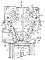
1 to 7 show a first embodiment of the present invention. FIG. 1 is a partial longitudinal sectional view of an internal combustion engine, FIG. 2 is a plan view taken along the
[0012]
1 and 2, the multi-cylinder internal combustion engine includes a
[0013]
The
[0014]
The intake valves VI, VI stems 21 that can open and close the
[0015]
Both intake valves VI and VI are opened and closed by an intake side
[0016]
The intake side
[0017]
The exhaust side
[0018]
The intake side and exhaust
[0019]
Incidentally, the intake side and exhaust side
[0020]
The intake-
[0021]
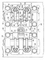
In FIG. 3, a first
[0022]
The first and second
[0023]
Referring to FIG. 4 together, the connecting
[0024]
Further, an arc-shaped
[0025]
With further reference to FIGS. 5 and 6, a
[0026]
The first and second
[0027]
Moreover, the width of the
[0028]
The first and
[0029]
The first
[0030]
A
[0031]
The
[0032]
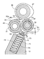
In FIG. 7, a tapered chamfered
[0033]
Referring to FIG. 6, a lost
[0034]
On the other hand, the
[0035]
In addition, the connecting
[0036]
Between the first
[0037]
The
[0038]
The
[0039]
The restricting
[0040]
A ring-shaped washer 91 is inserted on the outer end side of the
[0041]
In such an interlocking switching means 80, the hydraulic pressure of the
[0042]
In a high-speed operation region of the engine, a relatively high hydraulic pressure is applied to the
[0043]
Next, the operation of the first embodiment will be described. Each
[0044]
Therefore, the
[0045]
By the way, the
[0046]
Therefore, the load point acting on the
[0047]
Moreover, since the connecting
[0048]
[0049]
Thus, the
[0050]
In addition, since the deformation amount of the
[0051]
In the first
[0052]
Accordingly, it is not necessary to perform relief processing on the closed end side of the bottomed hole, compared with the case where the bottomed hole must be drilled in the
[0053]
In addition, since the washer 91 is inserted into the
[0054]
FIG. 8 illustrates the present invention. reference An example is shown, and the same reference numerals are given to portions corresponding to the first embodiment.
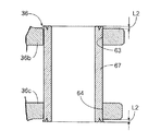
[0055]
Both ends of the
[0056]
this reference According to the example, as in the first embodiment, no components other than the
[0057]
FIG. 9 shows the first aspect of the present invention. 2 An example is shown above. First Parts corresponding to the embodiments are denoted by the same reference numerals.
[0058]
[0059]
The
[0060]
This first 2 According to the embodiment, by caulking and fixing to the first and
[0061]
As still another embodiment of the present invention, the caulking deformation portion of the roller shaft 67 'on the
[0062]
As mentioned above, the embodiment of the present invention And reference examples However, the present invention is not limited to the above-described embodiment, and various design changes can be made without departing from the present invention described in the claims.
[0063]
【The invention's effect】
As described above, according to the first aspect of the invention, the roller shaft can be easily fixed to the rocker arm while avoiding an increase in the number of parts and an increase in processing man-hours, and when the switching pin is moved to the interlocking position. The deformation of the end of the roller shaft on the side where the switching pin is received, that is, the second support wall side is suppressed to be small so that the switching pin can be smoothly fitted into the roller shaft, and the switching between the interlocking and the releasing of the interlocking by the switching pin of the adjacent rocker arm is smoothly performed. It can be. Further, since the roller shaft can be firmly held on the first support wall side, the press-fitting allowance on the second support wall side can be set small, and the deformation amount of the roller shaft on the second support wall side can be further increased. It can be made even smaller.
[0064]
According to the invention of
[Brief description of the drawings]
FIG. 1 is a partial longitudinal sectional view of an internal combustion engine.
FIG. 2 is a plan view taken in the direction of
FIG. 3 is an enlarged view taken along line 3-3 in FIG. 1;
4 is a cross-sectional view taken along line 4-4 of FIG.
5 is an enlarged cross-sectional view taken along line 5-5 of FIG.
6 is an enlarged sectional view taken along line 6-6 of FIG.
FIG. 7 is a cross-sectional view for explaining a structure for fixing a roller shaft to a rocker arm.
[Fig. 8] reference It is sectional drawing corresponding to FIG. 7 of an example.
FIG. 9 2 It is sectional drawing corresponding to FIG. 5 of an Example.
[Explanation of symbols]
30 ... Intake side valve operating device
35 ... second drive rocker arm
36 ... Free rocker arm
36b ... 1st support wall
36c ... second support wall
38 ... Intake side camshaft
47 ... Cam for high speed
58 ... Roller
67, 67 '... Roller shaft
81... Switching pin
Claims (2)
前記ローラ軸(67)が、第1支持壁(36b)にかしめ固定されるとともに第2支持壁(36c)に圧入され、前記ローラ軸(67)のかしめ固定による変形量が圧入による変形量よりも大きいことを特徴とする内燃機関の動弁装置。First and second support walls in which one of the rocker arms (35, 36) adjacent to each other (36) is disposed with a roller (58) in contact with a cam (47) provided on the camshaft (38). (36b, 36c) is provided with the second support wall (36c) arranged on the other rocker arm (35) side, and the roller (58) rotates between the first and second support walls (36b, 36c). A cylindrical roller shaft (67) to be supported freely is installed, and a switching pin (81) is slidably fitted to the other rocker arm (35). The switching pin (81) An interlocking position in which a part is fitted into the roller shaft (67) and the rocker arms (35, 36) are interlocked, and an interlock release position in which the entire pin is retracted from the roller shaft (67) to cancel the interlocking. Can slide between In the valve operating system of a internal combustion engine,
The roller shaft (67) is caulked and fixed to the first support wall (36b) and press-fitted into the second support wall (36c), and the deformation amount due to caulking and fixing of the roller shaft (67) is greater than the deformation amount due to press-fitting. A valve operating apparatus for an internal combustion engine characterized by being large .
Priority Applications (1)
| Application Number | Priority Date | Filing Date | Title |
|---|---|---|---|
| JP2000006266A JP4206183B2 (en) | 2000-01-12 | 2000-01-12 | Valve operating device for internal combustion engine |
Applications Claiming Priority (1)
| Application Number | Priority Date | Filing Date | Title |
|---|---|---|---|
| JP2000006266A JP4206183B2 (en) | 2000-01-12 | 2000-01-12 | Valve operating device for internal combustion engine |
Publications (2)
| Publication Number | Publication Date |
|---|---|
| JP2001193427A JP2001193427A (en) | 2001-07-17 |
| JP4206183B2 true JP4206183B2 (en) | 2009-01-07 |
Family
ID=18534823
Family Applications (1)
| Application Number | Title | Priority Date | Filing Date |
|---|---|---|---|
| JP2000006266A Expired - Fee Related JP4206183B2 (en) | 2000-01-12 | 2000-01-12 | Valve operating device for internal combustion engine |
Country Status (1)
| Country | Link |
|---|---|
| JP (1) | JP4206183B2 (en) |
Families Citing this family (2)
| Publication number | Priority date | Publication date | Assignee | Title |
|---|---|---|---|---|
| JP4931758B2 (en) * | 2007-10-05 | 2012-05-16 | 株式会社オティックス | Variable valve mechanism |
| JP2011163136A (en) * | 2010-02-05 | 2011-08-25 | Ntn Corp | Tappet for pump |
-
2000
- 2000-01-12 JP JP2000006266A patent/JP4206183B2/en not_active Expired - Fee Related
Also Published As
| Publication number | Publication date |
|---|---|
| JP2001193427A (en) | 2001-07-17 |
Similar Documents
| Publication | Publication Date | Title |
|---|---|---|
| JP3535431B2 (en) | Valve train for internal combustion engine | |
| JP3319794B2 (en) | SOHC type valve train for internal combustion engine | |
| US6425359B2 (en) | Valve moving apparatus of an internal combustion engine | |
| EP1172528B1 (en) | Valve drive device of four-stroke cycle engine | |
| JP3547912B2 (en) | Valve train for internal combustion engine | |
| US8813698B2 (en) | Variable valve apparatus of internal combustion engine | |
| JPH04231610A (en) | Rocker arm | |
| JP3366196B2 (en) | Valve train for internal combustion engine | |
| JP4310016B2 (en) | Valve operating device for internal combustion engine | |
| JP2000145422A (en) | Valve unit for multiple-cylinder internal combustion engine | |
| JP3535432B2 (en) | Valve train for internal combustion engine | |
| JP2517078Y2 (en) | Valve train for internal combustion engine | |
| EP0967367A2 (en) | Valve drive system for an internal combustion engine | |
| JP4206183B2 (en) | Valve operating device for internal combustion engine | |
| US5870984A (en) | Variable engine valve driver | |
| JP2013142328A (en) | Variable valve gear | |
| WO2005068790A1 (en) | Valve operating device for engine | |
| JP4326267B2 (en) | Valve operating device for multi-cylinder internal combustion engine | |
| JPH1181947A (en) | Valve system for internal combustion engine | |
| JP2007077962A (en) | Mounting method of variable valve train | |
| JP2584890Y2 (en) | Valve train for internal combustion engine | |
| JP4063960B2 (en) | Valve mechanism of multi-cylinder engine | |
| JP2001193420A (en) | Valve system for internal combustion engine | |
| JP2001289019A (en) | Valve system for internal combustion engine | |
| JP2001193425A (en) | Valve system for internal combustion engine |
Legal Events
| Date | Code | Title | Description |
|---|---|---|---|
| A621 | Written request for application examination |
Free format text: JAPANESE INTERMEDIATE CODE: A621 Effective date: 20061201 |
|
| A977 | Report on retrieval |
Free format text: JAPANESE INTERMEDIATE CODE: A971007 Effective date: 20080630 |
|
| A131 | Notification of reasons for refusal |
Free format text: JAPANESE INTERMEDIATE CODE: A131 Effective date: 20080702 |
|
| RD02 | Notification of acceptance of power of attorney |
Free format text: JAPANESE INTERMEDIATE CODE: A7422 Effective date: 20080818 |
|
| A521 | Written amendment |
Free format text: JAPANESE INTERMEDIATE CODE: A523 Effective date: 20080827 |
|
| TRDD | Decision of grant or rejection written | ||
| A01 | Written decision to grant a patent or to grant a registration (utility model) |
Free format text: JAPANESE INTERMEDIATE CODE: A01 Effective date: 20080930 |
|
| A01 | Written decision to grant a patent or to grant a registration (utility model) |
Free format text: JAPANESE INTERMEDIATE CODE: A01 |
|
| A61 | First payment of annual fees (during grant procedure) |
Free format text: JAPANESE INTERMEDIATE CODE: A61 Effective date: 20081020 |
|
| FPAY | Renewal fee payment (event date is renewal date of database) |
Free format text: PAYMENT UNTIL: 20111024 Year of fee payment: 3 |
|
| R150 | Certificate of patent or registration of utility model |
Free format text: JAPANESE INTERMEDIATE CODE: R150 |
|
| FPAY | Renewal fee payment (event date is renewal date of database) |
Free format text: PAYMENT UNTIL: 20111024 Year of fee payment: 3 |
|
| FPAY | Renewal fee payment (event date is renewal date of database) |
Free format text: PAYMENT UNTIL: 20121024 Year of fee payment: 4 |
|
| FPAY | Renewal fee payment (event date is renewal date of database) |
Free format text: PAYMENT UNTIL: 20131024 Year of fee payment: 5 |
|
| LAPS | Cancellation because of no payment of annual fees |