JP4205657B2 - Optical termination box - Google Patents
Optical termination box Download PDFInfo
- Publication number
- JP4205657B2 JP4205657B2 JP2004331501A JP2004331501A JP4205657B2 JP 4205657 B2 JP4205657 B2 JP 4205657B2 JP 2004331501 A JP2004331501 A JP 2004331501A JP 2004331501 A JP2004331501 A JP 2004331501A JP 4205657 B2 JP4205657 B2 JP 4205657B2
- Authority
- JP
- Japan
- Prior art keywords
- optical
- termination box
- introduction port
- optical fiber
- holes
- Prior art date
- Legal status (The legal status is an assumption and is not a legal conclusion. Google has not performed a legal analysis and makes no representation as to the accuracy of the status listed.)
- Expired - Fee Related
Links
Images


Description
本発明は、光成端部に係り、特に、光ファイバ同士の接続部及び前記光ファイバの余長を収納する光成端箱に関するものである。 The present invention relates to an optical termination portion, and more particularly to an optical termination box that houses a connection portion between optical fibers and an extra length of the optical fiber.
近年、マンションなどの集合住宅や家庭でのFTTH(Fiber to the Home)の導入が進展している。図9は上述したFTTHシステム1の一例を示す図である。2はインターネット、3はプロバイダ、4は光ファイバ網、5は家庭である。家庭5内には、パソコン51の他に光成端箱52、メディアコンバータ53が備えてある。
In recent years, the introduction of FTTH (Fiber to the Home) in apartment houses such as condominiums and homes is progressing. FIG. 9 is a diagram showing an example of the
上述した光成端箱52には、家庭5にまで届いているドロップ光ファイバケーブル54が接続されている。光成端箱52とメディアコンバータ53との間は、光ファイバコード55で接続されている。また、メディアコンバータ53とパソコン51との間は、電気ケーブル56で接続されている。
A drop
光成端箱52は、家庭5にまで届いているドロップ光ファイバケーブル54に、コネクタ付きの光ファイバコード55を接続して成端化するためのものであり、その接続部と、光ファイバの余長とが収容される。メディアコンバータ53は、光ファイバコード55を介して入力してきた光信号を電気信号に変換する機能及び電気ケーブル56を介して入力してきた電気信号を光信号に変換する機能を有する。
The
上述した光成端箱52は、例えば特許文献1〜3に示すように、メディアコンバータ53とは独立して設けられいる。このため光成端箱52は、図9に示すように、壁などにメディアコンバータ53と並列に設けられることが多く、光成端箱52から導出され、メディアコンバータ53に導入される光ファイバコード55の露出部分が多くなってしまう。そのため、サービス運用中において、ユーザが足を引っかけて光ファイバコード55を断線させるなどの障害が発生するという問題があった。
The
そこで、このような問題を解決するために、メディアコンバータ53の底面に接続部とファイバの余長分を収容する光成端箱52を一体に形成するものが提案されている(例えば特許文献4)。しかしながら、この場合、光成端箱52とは別体の汎用のメディアコンバータ53を使用することができず、コスト的に問題が生じてしまう。
Therefore, in order to solve such a problem, there has been proposed one in which an
また、光成端箱への光ファイバケーブル54の導入口が通常1〜2箇所しかないためケーブル導入方向が制限されてしまい、集合住宅など十分なスペースがない場合には成端に支障が発生する場合があった。
そこで、本発明は、上記のような問題点に着目し、汎用のメディアコンバータを使用しても、光ファイバの露出を抑えて、ユーザが足を引っかけるなどの問題を安価に解消できる光成端箱を提供することを課題とする。 Therefore, the present invention pays attention to the above-described problems, and even if a general-purpose media converter is used, the optical termination that can suppress the exposure of the optical fiber and solve the problem such as the user getting stuck at a low cost. It is an object to provide a box.
請求項1記載の発明は、光ファイバ同士の接続部及び前記光ファイバの余長を収納する光成端箱であって、光信号及び電気信号を相互変換する光電変換箱の一面に、当該光成端箱を取り付けるための成端箱側取付部を備え、前記光電変換箱の一面に取り付けられる面を除いた全ての面に前記光ファイバの導入口が形成され、前記導入口から導入した光ファイバを当該光成端箱の一面との間に挟んで結束する結束バンドを通すための一対の貫通穴から構成される保持部が前記一面に設けられ、前記一対の貫通穴は、側面に設けられた一導入口を通り、当該一導入口への導入方向に延びる第1の直線と、前記一導入口が設けられた側面と隣接した側面に設けられた他の導入口を通り、当該他の導入口への導入方向に延びる第2の直線とが交わる点に、前記一対の貫通穴間の中心が位置し、かつ、貫通穴間方向が第1及び第2の直線の両者に対して斜めに交わるように、設けられていることを特徴とする光成端箱に存する。
The invention according to
請求項1記載の発明によれば、光電変換箱の一面に取り付けられる面を除いた全ての面に光ファイバの導入口が形成されている。従って、全ての面から光ファイバを導入することができる。 According to the first aspect of the invention, inlet optical fiber is formed on all surfaces except the surface to be attached to one surface of the photoelectric conversion box. Therefore, the optical fiber can be introduced from all surfaces.
また、請求項1記載の発明によれば、導入口から導入した光ファイバを光成端箱の一面との間に挟んで結束する結束バンドを通すための一対の貫通穴から構成される保持部が一面に設けられている。一対の貫通穴は、側面に設けられた一導入口を通り、当該一導入口への導入方向に延びる第1の直線と、一導入口が設けられた側面と隣接した側面に設けられた他の導入口を通り、当該他の導入口への導入方向に延びる第2の直線とが交わる点に、一対の貫通穴間の中心が位置し、かつ、貫通孔間方向が第1及び第2の直線の両者に対して斜めに交わるように、設けられている。 Further, according to the first aspect of the invention, the holding portion including a pair of through holes for passing interposed therebetween binding band for binding between the one surface of the optical termination box optical fibers introduced from the inlet Is provided on one side. The pair of through holes pass through one introduction port provided on the side surface and extend in the introduction direction to the one introduction port, and the other provided on the side surface adjacent to the side surface on which the one introduction port is provided The center between the pair of through holes is located at the point where the second straight line extending through the other inlet and extending in the direction of introduction to the other inlet is intersected, and the direction between the through holes is the first and second directions. It is provided so that it may cross diagonally with respect to both of these straight lines.
以上のように、一対の貫通穴を設けることにより、光ファイバを一導入口から導入した場合でも、他導入口から導入した場合でも、一対の貫通穴に通した結束バンドにより光ファイバを結束することができ、一導入口用と他導入口用と別々に貫通穴を設ける必要がない。 As described above, by providing a pair of through holes, the optical fiber is bound by a binding band that passes through the pair of through holes, regardless of whether the optical fiber is introduced from one introduction port or another introduction port. It is not necessary to provide a through hole separately for one introduction port and for the other introduction port.
以上説明したように請求項1記載の発明によれば、全ての面から光ファイバを導入することができるので、導入方向が制限されてしまうことがない光成端箱を得ることができる。 As described above, according to the first aspect of the present invention, since the optical fiber can be introduced from all sides, an optical termination box in which the introduction direction is not limited can be obtained.
また、請求項1記載の発明によれば、一対の貫通穴を設けることにより、光ファイバを一導入口から導入した場合でも、他の導入口から導入した場合でも、一対の貫通穴に通した結束バンドにより光ファイバを結束することができ、一導入口用と他導入口用と別々に貫通穴を設ける必要がないので、コストダウンを図った光成端箱を得ることができる。 In addition, according to the first aspect of the present invention, by providing a pair of through holes, the optical fiber is passed through the pair of through holes regardless of whether the optical fiber is introduced from one introduction port or the other introduction port. The optical fiber can be bundled by the bundling band, and it is not necessary to provide a through hole separately for one introduction port and for the other introduction port, so that an optical termination box with reduced cost can be obtained.
以下、本発明について図面を参照して説明する。光成端箱は、正面が開口している受け皿状の光成端箱本体と、その本体開口部を塞ぐ蓋体とから構成されている。図1(a)〜(e)は各々、本発明の光成端箱100を構成する光成端箱本体110の正面図、左側面図、右側面図、上側面図及び下側面図を示す図である。図2は、本発明の光成端箱を構成する蓋体120の正面図である。
The present invention will be described below with reference to the drawings. The optical termination box is composed of a saucer-shaped optical termination box main body whose front is open and a lid that closes the main body opening. FIGS. 1A to 1E respectively show a front view, a left side view, a right side view, an upper side view, and a lower side view of an optical
本実施形態の光成端箱100は、家庭にまで届いているドロップ光ファイバケーブル130(=光ファイバ)と、一端に光コネクタ131aが設けられた光ファイバコード131の他端との接続部及び光ファイバコード131の余長を収納するための箱である。同図に示すように、光成端箱本体110の左右、上下4側面には各々ドロップ光ファイバケーブル130を導入するための導入口111L、111R、111U、111Dが設けられている。また、背面にもドロップ光ファイバケーブル130を導入するための導入口111Bが2カ所設けられている。
The
上述した構成によれば、メディアコンバータ(=光電変換箱)の背面(=一面)に取り付けられる正面を除いた全ての面にドロップ光ファイバケーブル130の導入口111L、111R、111U、111D、111Bが設けられている。これにより、左右、上下4側面、さらに背面からもドロップ光ファイバケーブル130を導入することができ、ドロップ光ファイバケーブル130の光成端箱100内への導入方向が制限されることがない。
According to the configuration described above, the
光成端箱100の背面には、導入口111L、111R、111U、111D、111Bから導入してきたドロップ光ファイバケーブル130を、インシュロック118(=結束バンド)で背面との間に挟んで結束することにより、保持する保持部112と、ドロップ光ファイバケーブル130と光ファイバコード131との接続部を補強する補強熱スリーブ132を挟んで保持する接続部収容部113とが設けられている。
A drop
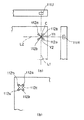
上述した保持部112は、図3(a)に示すように、上述したインシュロック118を通すための一対の貫通穴112a、112bが2対設けられている。この一対の貫通穴112a、112bの配置位置としては、上導入口111Uを通り、上導入口111Uへの導入方向に延びる第1の直線L1と、この上導入口111Uが設けられた側面と隣接した側面に設けられた右導入口111Rを通り、右導入口111Rへの導入方向に延びる第2の直線L2とが交わる点に、一対の貫通穴112a、112b間中心Cが位置し、かつ、貫通穴間方向Y1、Y2が第1及び第2の直線L1、L2の何れとも平行にならない位置に配置されている。
As shown in FIG. 3A, the
以上のように貫通穴112a、112bを設けることにより、光ファイバケーブル130を上導入口111Uから導入した場合でも、右導入口111Rから導入した場合でも、一対の貫通穴112a、112bに通したインシュロック118により光ファイバケーブル130を結束することができ、上導入口111U用と右導入口111R用と別々に貫通穴112a、112bを設ける必要がなく、コストダウンを図ることができる。下導入口111D、左導入口111Lに対しても同様に、下導入口111Dから導入した場合でも、左導入口111Lから導入した場合でも、共通の貫通穴112a、112bに通したインシュロック118で光ファイバケーブル130を結束できるように配置されている。また、光成端箱100の背面外側には、図3(b)に示すように、インシュロック118を収容する収容溝112cが形成され、背面外側において貫通穴112a、112bに通して結束したインシュロック118部分が突起せず、外側背面がフラットになるようにしている。
By providing the through
また、光成端箱100の下側面には、アダプタ133を取り付けるためのアダプタ取付穴114が設けられている。さらに、光成端箱100の内部背面には、光ファイバコード131の余長処理部115と、光成端箱100を壁に取り付けるための引っかけ穴116と、背面中央から正面に向かって立設した中央インサート117Cと、この中央インサート117Cの上下に設けられ、正面に向かって立設した上下インサート117U、117Dが形成されている。
An
上述したインサート117C、117U、117Dは、図4に示すように、背面から正面に向かって立設する凸状部であり、その頂面にネジ穴17a(=挿入穴)が形成されている。なお、中央インサート117Cは蓋体120を光成端部本体110に取り付けるためのものであり、上下インサート117U、117Dは、成端箱側取付部として機能し、後述するメディアコンバータ(=光電変換箱)の背面に、光成端箱100を取り付けるために設けられたものである。
As shown in FIG. 4, the above-described inserts 117 </ b> C, 117 </ b> U, and 117 </ b> D are convex portions that are erected from the back toward the front, and a screw hole 17 a (= insertion hole) is formed on the top surface. The
また、図2に示すように光成端箱100を構成する蓋体120には、上述した中央、上下インサート117C、117U、117Dに対向する位置に貫通穴120C、120U、120Dが形成され、光成端箱本体110の正面開口部に蓋体120を取り付けた状態であっても、貫通穴120C、120U、120Dを介して中央、上下インサート117C、117U、117Dに形成されたネジ穴117aが露出するようになっている。
Further, as shown in FIG. 2, the
次に、上述した構成の光成端箱100への接続部及び余長の収容について以下説明する。まず、ドロップ光ファイバケーブル130は、導入口111L、111R、111U、111D、111Bの何れか1つから光成端箱100内部に導入されている。本実施形態では、図1に示すように、上側面に設けられた導入口111Uから導入した場合について説明する。
Next, accommodation of the connecting portion and the extra length to the
導入口111Uから導入されたドロップ光ファイバケーブル130は、一対の貫通穴112a、112bに通したインシュロック118によって結束され、光成端箱100から外れないようになっている。またドロップ光ファイバケーブル130、光ファイバコード131の一端は、被覆が削られ、それぞれの光ファイバ心線130a、131bが露出している。さらに、光ファイバ心線130a、131bの一端も被覆が削除され、ガラス部分が露出されている。
The drop
上述した光ファイバ心線130a、131bのガラス部分は融着接続やメカニカルスプライスにより接続されている。また、融着接続された接続部は被覆がなくガラスが露出しているため、この接続部に補強熱スリーブ132を被せて、熱収縮させて、強さを補強している。この補強熱スリーブ132は、接続部収容部113に挟まれて保持される。その後、光ファイバコード131は余長処理部115に沿って巻き付けられて、余長処理された後、一端に設けられた光コネクタ131aがアダプタ133にコネクタ接続される。
The glass portions of the optical
上述したように接続部収納及び余長処理が行われた後、図2に示す蓋体120を光成端箱本体110の正面開口部に被せ、ネジ(図示せず)を蓋体120の貫通孔120Cを貫通させて、中央インサート117Cのネジ穴117aに挿入して、ネジ止めすることにより、蓋体120を光成端箱本体110に取り付ける。
After the connection portion storage and extra length processing are performed as described above, the
上述した光成端箱100とメディアコンバータとの接続は両端に光コネクタが設けられた接続光ファイバを用いて行われる。詳しくは、接続光ファイバの一端に設けられた光コネクタを光成端箱100に設けたアダプタ133に接続し、他端に設けられた光コネクタをメディアコンバータに接続する。
The connection between the
次に、上述した構成の光成端箱100のメディアコンバータ一面への取付について説明する。メディアコンバータとしては、壁にねじ込まれたネジなどの突起物に引っかけるタイプのものについて説明する。このようなタイプのメディアコンバータ200には、図5に示すように、その背面に引っかけ穴201(=変換箱側取付部)が設けられている。
Next, attachment of the
同図に示すように、この引っかけ穴201は、ネジ頭が挿入できる程度の大きさのネジ頭用挿入部201aと、ネジ頭部より小さく、かつ、ネジ軸部が挿入できる程度の大きさのネジ軸挿入部201bとが連通した状態で形成されている。このような引っかけタイプのメディアコンバータ200に対しては、図6に示すように、予めネジ150を、上下インサート117U、117Dのネジ穴17aにねじ込んで光成端箱100に取り付けておく。
As shown in the figure, the
その後、メディアコンバータ200の引っかけ穴201のネジ頭挿入部201aからネジ150のネジ頭150aを挿入し、メディアコンバータ200をスライドしてネジ軸挿入部201bにネジ軸150bを挿入する。これにより、メディアコンバータ200の引っかけ穴201からネジ150が抜け落ちることなく、メディアコンバータ200の背面に光成端箱100を取り付けることができる。そして、図7に示すように、メディアコンバータ200の背面に光成端箱100を取り付けた状態で、光成端箱100背面に設けた引っかけ穴116(図1参照)を、壁に設けたネジに引っかけて取り付ける。
Thereafter, the screw head 150a of the
また、メディアコンバータ200として、背面を壁にネジ止めするタイプのものについて説明する。このようなタイプのメディアコンバータ200には、図8に示すように、その背面にネジ軸挿入穴202(=変換箱側取付部)が設けられている。このネジ軸挿入穴202は、ネジ頭150aより小さく、かつ、ネジ軸150bが挿入できる程度の大きさである。
The
このようなネジ止めタイプのメディアコンバータ200の場合、予めネジ150をメディアコンバータ200のネジ軸挿入穴202に挿入した状態で、上下インサート117U、117Dのネジ穴117aにねじ込んで光成端箱100を取り付ける。この場合も、図7に示すように、メディアコンバータ200の背面に光成端箱100を取り付けた状態で、光成端箱100背面に設けた引っかけ穴116を、壁に設けたネジに引っかけて取り付ける。
In the case of such a screw-
上述したように光成端箱100によれば、上下インサート117U、117Dにより、光成端箱100と別体に形成されている汎用のメディアコンバータ200の背面に取り付けることができる。これにより、図7(b)に示すように、光成端箱100から導出され、メディアコンバータ200に導入する両端コネクタ付き光ファイバ160をメディアコンバータ200の背後に隠すことができ、汎用のメディアコンバータ200を使用しても、光ファイバ160の露出を抑えて、ユーザが足を引っかけるなどの問題を安価に解消できる。
As described above, the
また、頂面にネジ穴117aが形成されたインサート117U、117Dを成端箱側取付部とすることにより、図6に示すような引っかけタイプのメディアコンバータ200でも、図8に示すようなネジ止めタイプのメディアコンバータ200にも取り付けることができる。
Further, by using the
なお、上述した実施形態では、汎用のメディアコンバータ200に設けてある引っかけ穴201や、ネジ軸挿入穴202などのコンバータ側取付部を利用して、光成端箱100をメディアコンバータ200の背面に取り付けていた。しかしながら、メディアコンバータ200の引っかけ穴201やネジ軸挿入穴202などを使わずに単に、光成端部100に、メディアコンバータ200の背面からメディアコンバータ200を把持して取り付けるような取付部を持たせることも考えられる。しかしながら、この場合、取付部の構造自体が大きくなってしまうし、取付自体も弱いものとなる可能性がある。このため、本実施形態のように、コンバータ側取付部を利用して取り付けるものの方が望ましい。
In the above-described embodiment, the
また、上述した実施形態では、インサート117U、117Dの頂面に形成したネジ穴117aに、ネジ穴117aにネジを挿入することにより、メディアコンバータ200を取り付けていた。しかしながら、例えば、頂面に単なる挿入穴を形成し、その挿入穴に棒状体を圧入することにより、メディアコンバータ200を取り付けることも考えられる。
In the above-described embodiment, the
また、上述した実施形態では、導入口111Uからドロップ光ファイバケーブル130を導入して、図面右上に設けた保持部112で保持していた。しかしながら、導入口111Rからドロップ光ファイバケーブル130を導入してもよく、この場合も、保持部112で保持する。また、導入口111D又は111Lから導入する場合は、図面左下の保持部112で保持する。さらに、導入口111Bから導入する場合は、この導入口111B近傍に設けられた図面右下、左上にある保持部112で保持する。
In the above-described embodiment, the drop
100 光成端箱
111R 導入口
111L 導入口
111U 導入口
111D 導入口
111B 導入口
112 保持部
112a 一対の貫通穴
112b 一対の貫通穴
117U インサート(成端箱側取付部、凸状部)
117D インサート(成端箱側取付部、凸状部)
117a ネジ穴(挿入穴)
130 ドロップ光ファイバケーブル(光ファイバ)
131 光ファイバコード(光ファイバ)
200 メディアコンバータ(光電変換箱)
201 引っかけ穴(変換箱側取付部)
202 ネジ軸挿入穴(変換箱側取付部)
L1 第1の直線
L2 第2の直線
100
117D Insert (Termination box side mounting part, convex part)
117a Screw hole (insertion hole)
130 drop optical fiber cable (optical fiber)
131 Optical fiber cord (optical fiber)
200 Media converter (photoelectric conversion box)
201 Hook hole (Conversion box side mounting part)
202 Screw shaft insertion hole (Conversion box side mounting part)
L1 first straight line L2 second straight line
Claims (1)
光信号及び電気信号を相互変換する光電変換箱の一面に、当該光成端箱を取り付けるための成端箱側取付部を備え、
前記光電変換箱の一面に取り付けられる面を除いた全ての面に前記光ファイバの導入口が形成され、
前記導入口から導入した光ファイバを当該光成端箱の一面との間に挟んで結束する結束バンドを通すための一対の貫通穴から構成される保持部が前記一面に設けられ、
前記一対の貫通穴は、側面に設けられた一導入口を通り、当該一導入口への導入方向に延びる第1の直線と、前記一導入口が設けられた側面と隣接した側面に設けられた他の導入口を通り、当該他の導入口への導入方向に延びる第2の直線とが交わる点に、前記一対の貫通穴間の中心が位置し、かつ、貫通穴間方向が第1及び第2の直線の両者に対して斜めに交わるように、設けられていることを特徴とする光成端箱。 An optical termination box that houses the connection between optical fibers and the extra length of the optical fiber,
On one side of the photoelectric conversion box that mutually converts the optical signal and the electrical signal, a termination box side mounting portion for mounting the optical termination box is provided,
The optical fiber inlet is formed on all surfaces except the surface attached to one surface of the photoelectric conversion box,
A holding part constituted by a pair of through holes for passing a binding band for bundling the optical fiber introduced from the introduction port between the optical termination box and one surface is provided on the one surface,
The pair of through holes are provided on a side surface adjacent to the first straight line extending in the introduction direction to the one introduction port through the one introduction port provided on the side surface and the side surface provided with the one introduction port. The center between the pair of through holes is located at a point where the second straight line extending in the introduction direction to the other introduction port intersects with the other introduction port, and the direction between the through holes is the first. And an optical termination box provided so as to cross at an angle with respect to both the second straight line and the second straight line .
Priority Applications (1)
| Application Number | Priority Date | Filing Date | Title |
|---|---|---|---|
| JP2004331501A JP4205657B2 (en) | 2004-11-16 | 2004-11-16 | Optical termination box |
Applications Claiming Priority (1)
| Application Number | Priority Date | Filing Date | Title |
|---|---|---|---|
| JP2004331501A JP4205657B2 (en) | 2004-11-16 | 2004-11-16 | Optical termination box |
Publications (2)
| Publication Number | Publication Date |
|---|---|
| JP2006145582A JP2006145582A (en) | 2006-06-08 |
| JP4205657B2 true JP4205657B2 (en) | 2009-01-07 |
Family
ID=36625405
Family Applications (1)
| Application Number | Title | Priority Date | Filing Date |
|---|---|---|---|
| JP2004331501A Expired - Fee Related JP4205657B2 (en) | 2004-11-16 | 2004-11-16 | Optical termination box |
Country Status (1)
| Country | Link |
|---|---|
| JP (1) | JP4205657B2 (en) |
Families Citing this family (3)
| Publication number | Priority date | Publication date | Assignee | Title |
|---|---|---|---|---|
| JP2008180820A (en) * | 2007-01-23 | 2008-08-07 | Yazaki Corp | Optical connection box and signal distribution unit equipped with the same |
| JP5178628B2 (en) * | 2009-05-18 | 2013-04-10 | 日東工業株式会社 | Optical connection box wiring holding structure |
| WO2014003826A1 (en) * | 2012-06-28 | 2014-01-03 | Ofs Fitel, Llc | Combination customer splice point module and optical network terminal mount |
-
2004
- 2004-11-16 JP JP2004331501A patent/JP4205657B2/en not_active Expired - Fee Related
Also Published As
| Publication number | Publication date |
|---|---|
| JP2006145582A (en) | 2006-06-08 |
Similar Documents
| Publication | Publication Date | Title |
|---|---|---|
| US9810861B2 (en) | Ruggedized optical fiber connection structures and assemblies | |
| KR200337929Y1 (en) | A Housing for purchase of optical fiber adapter | |
| JP4869677B2 (en) | Splitter module | |
| TW201028752A (en) | Telecommunications outlet box | |
| WO2010134157A1 (en) | Splitter module | |
| JP4886728B2 (en) | Splitter module | |
| JP5432469B2 (en) | Splitter module | |
| JP4917505B2 (en) | Light rosette | |
| JP4205657B2 (en) | Optical termination box | |
| JP2008170743A (en) | Outlet and optical wiring method therefor | |
| JP2008096668A (en) | Optical cabinet | |
| JP2008224998A (en) | Closure for optical cable connection and optical wiring system | |
| JP5108730B2 (en) | Splitter module | |
| JP2010019986A (en) | Closure for optical cable connection | |
| JP2008129166A (en) | Optical fiber wiring system and splitter box | |
| JP4614864B2 (en) | Communication equipment | |
| JP4963935B2 (en) | Light cabinet | |
| JP2008176108A (en) | Outlet | |
| JP5415905B2 (en) | Two-core optical outlet | |
| JP5320036B2 (en) | Splitter module | |
| JP4962954B2 (en) | Optical receiver | |
| JP4597872B2 (en) | Optical connection box | |
| JP4475518B2 (en) | Mounting structure of adapter and fixing member | |
| JP4540530B2 (en) | Optical fiber connection structure of optical terminal equipment | |
| JP5889612B2 (en) | Optical cable connection module |
Legal Events
| Date | Code | Title | Description |
|---|---|---|---|
| A621 | Written request for application examination |
Free format text: JAPANESE INTERMEDIATE CODE: A621 Effective date: 20070414 |
|
| A977 | Report on retrieval |
Free format text: JAPANESE INTERMEDIATE CODE: A971007 Effective date: 20080421 |
|
| A131 | Notification of reasons for refusal |
Free format text: JAPANESE INTERMEDIATE CODE: A131 Effective date: 20080430 |
|
| A521 | Written amendment |
Free format text: JAPANESE INTERMEDIATE CODE: A523 Effective date: 20080627 |
|
| A131 | Notification of reasons for refusal |
Free format text: JAPANESE INTERMEDIATE CODE: A131 Effective date: 20080722 |
|
| A521 | Written amendment |
Free format text: JAPANESE INTERMEDIATE CODE: A523 Effective date: 20080919 |
|
| TRDD | Decision of grant or rejection written | ||
| A01 | Written decision to grant a patent or to grant a registration (utility model) |
Free format text: JAPANESE INTERMEDIATE CODE: A01 Effective date: 20081014 |
|
| A01 | Written decision to grant a patent or to grant a registration (utility model) |
Free format text: JAPANESE INTERMEDIATE CODE: A01 |
|
| A61 | First payment of annual fees (during grant procedure) |
Free format text: JAPANESE INTERMEDIATE CODE: A61 Effective date: 20081016 |
|
| FPAY | Renewal fee payment (event date is renewal date of database) |
Free format text: PAYMENT UNTIL: 20111024 Year of fee payment: 3 |
|
| R150 | Certificate of patent or registration of utility model |
Free format text: JAPANESE INTERMEDIATE CODE: R150 |
|
| FPAY | Renewal fee payment (event date is renewal date of database) |
Free format text: PAYMENT UNTIL: 20121024 Year of fee payment: 4 |
|
| FPAY | Renewal fee payment (event date is renewal date of database) |
Free format text: PAYMENT UNTIL: 20131024 Year of fee payment: 5 |
|
| S111 | Request for change of ownership or part of ownership |
Free format text: JAPANESE INTERMEDIATE CODE: R313111 |
|
| FPAY | Renewal fee payment (event date is renewal date of database) |
Free format text: PAYMENT UNTIL: 20131024 Year of fee payment: 5 |
|
| R350 | Written notification of registration of transfer |
Free format text: JAPANESE INTERMEDIATE CODE: R350 |
|
| LAPS | Cancellation because of no payment of annual fees |