JP4205129B2 - Integrated GPS inertial system - Google Patents
Integrated GPS inertial system Download PDFInfo
- Publication number
- JP4205129B2 JP4205129B2 JP2006500443A JP2006500443A JP4205129B2 JP 4205129 B2 JP4205129 B2 JP 4205129B2 JP 2006500443 A JP2006500443 A JP 2006500443A JP 2006500443 A JP2006500443 A JP 2006500443A JP 4205129 B2 JP4205129 B2 JP 4205129B2
- Authority
- JP
- Japan
- Prior art keywords
- signal
- data
- receiver
- satellite
- channel
- Prior art date
- Legal status (The legal status is an assumption and is not a legal conclusion. Google has not performed a legal analysis and makes no representation as to the accuracy of the status listed.)
- Expired - Lifetime
Links
- 238000009434 installation Methods 0.000 abstract description 2
- 238000005259 measurement Methods 0.000 abstract description 2
- 230000004048 modification Effects 0.000 abstract 1
- 238000011084 recovery Methods 0.000 abstract 1
- 238000009420 retrofitting Methods 0.000 abstract 1
- 230000001133 acceleration Effects 0.000 description 2
- 230000005540 biological transmission Effects 0.000 description 2
- 230000002238 attenuated effect Effects 0.000 description 1
- 230000010354 integration Effects 0.000 description 1
- 238000000034 method Methods 0.000 description 1
Images
Classifications
-
- G—PHYSICS
- G01—MEASURING; TESTING
- G01S—RADIO DIRECTION-FINDING; RADIO NAVIGATION; DETERMINING DISTANCE OR VELOCITY BY USE OF RADIO WAVES; LOCATING OR PRESENCE-DETECTING BY USE OF THE REFLECTION OR RERADIATION OF RADIO WAVES; ANALOGOUS ARRANGEMENTS USING OTHER WAVES
- G01S19/00—Satellite radio beacon positioning systems; Determining position, velocity or attitude using signals transmitted by such systems
- G01S19/38—Determining a navigation solution using signals transmitted by a satellite radio beacon positioning system
- G01S19/39—Determining a navigation solution using signals transmitted by a satellite radio beacon positioning system the satellite radio beacon positioning system transmitting time-stamped messages, e.g. GPS [Global Positioning System], GLONASS [Global Orbiting Navigation Satellite System] or GALILEO
- G01S19/42—Determining position
- G01S19/48—Determining position by combining or switching between position solutions derived from the satellite radio beacon positioning system and position solutions derived from a further system
- G01S19/49—Determining position by combining or switching between position solutions derived from the satellite radio beacon positioning system and position solutions derived from a further system whereby the further system is an inertial position system, e.g. loosely-coupled
-
- G—PHYSICS
- G01—MEASURING; TESTING
- G01S—RADIO DIRECTION-FINDING; RADIO NAVIGATION; DETERMINING DISTANCE OR VELOCITY BY USE OF RADIO WAVES; LOCATING OR PRESENCE-DETECTING BY USE OF THE REFLECTION OR RERADIATION OF RADIO WAVES; ANALOGOUS ARRANGEMENTS USING OTHER WAVES
- G01S19/00—Satellite radio beacon positioning systems; Determining position, velocity or attitude using signals transmitted by such systems
- G01S19/01—Satellite radio beacon positioning systems transmitting time-stamped messages, e.g. GPS [Global Positioning System], GLONASS [Global Orbiting Navigation Satellite System] or GALILEO
- G01S19/13—Receivers
- G01S19/35—Constructional details or hardware or software details of the signal processing chain
Landscapes
- Engineering & Computer Science (AREA)
- Radar, Positioning & Navigation (AREA)
- Remote Sensing (AREA)
- Computer Networks & Wireless Communication (AREA)
- Physics & Mathematics (AREA)
- General Physics & Mathematics (AREA)
- Signal Processing (AREA)
- Position Fixing By Use Of Radio Waves (AREA)
- Navigation (AREA)
- Road Repair (AREA)
Abstract
Description
本発明は、GPSと慣性を組み合わせた位置探知器に関する。詳しくは、本発明は、GPS受信機に接続されたアンテナユニットの中に慣性センサを配置したシステムに関する。 The present invention relates to a position detector that combines GPS and inertia. Specifically, the present invention relates to a system in which an inertial sensor is arranged in an antenna unit connected to a GPS receiver.
近年、グローバル・ポジショニング・システム(GPS)受信機を慣性センサと組み合わせて信頼性の高い位置推定を行い、その位置を比較的短いインターバルで更新することが可能になっている。詳しくは、GPS受信機は、安価な慣性センサから得られる位置推定に比べて正確な位置推定が本来可能である。しかしながら、GPS受信機を自動車に搭載すると、周回するGPS衛星から受信された信号が、木や丘などの自然環境物、あるいは建物やトンネルなどの人工構造物によって減衰され、GPS受信機はドロップアウトされる。また、GPSシステムの位置更新は遅すぎて、航空機のオートパイロットシステムのような一部の制御システムには使用できないことがある。 In recent years, it has become possible to perform reliable position estimation by combining a global positioning system (GPS) receiver with an inertial sensor and update the position at a relatively short interval. Specifically, the GPS receiver is inherently capable of accurate position estimation as compared with position estimation obtained from an inexpensive inertial sensor. However, when a GPS receiver is mounted on an automobile, signals received from orbiting GPS satellites are attenuated by natural environment objects such as trees and hills, or artificial structures such as buildings and tunnels, and the GPS receiver is dropped out. Is done. Also, GPS system location updates are too slow and may not be available for some control systems, such as aircraft autopilot systems.
一方、慣性センサではそのような問題が発生しない。しかしながら、慣性センサを安価な部品で実現すると、慣性センサの位置推定の精度は、GPSだけで推定する場合に比べて非常に低くなる。 On the other hand, such a problem does not occur in the inertial sensor. However, if the inertial sensor is realized with inexpensive parts, the accuracy of the position estimation of the inertial sensor is very low as compared with the case of estimation using only GPS.
そのため、2つのシステムを組み合わせ、GPS位置更新を使用して慣性センサを校正することが行われている。慣性センサの出力を数学的に積分することにより、大抵の制御システムで使用するのに十分な速度で正確な位置推定を行うことが可能になる。また、慣性センサが十分な時間にわたってその校正状態を維持することで、GPS信号がドロップアウトしている間にも正確な推定が可能になる。 Therefore, two systems are combined to calibrate the inertial sensor using GPS position update. Mathematical integration of the inertial sensor output enables accurate position estimation at a speed sufficient for use in most control systems. In addition, by maintaining the calibration state of the inertial sensor for a sufficient time, accurate estimation is possible even when the GPS signal is being dropped out.
本発明は、既存の装置に必要以上の変更を加えることなく、GPS受信機の新たな設置にもGPS受信機の改良にも適した安価なGPS慣性システムに関する。具体的には、慣性センサをGPSアンテナのハウジングの中に組み込み、慣性センサの出力を、GPSシステムで使用されるのと同じデータ変調方式を使用して変調し、GPS搬送波と同じ周波数の無線周波数搬送波に載せる。 The present invention relates to an inexpensive GPS inertia system suitable for new installation of GPS receivers and improvement of GPS receivers without making unnecessary changes to existing devices. Specifically, the inertial sensor is built into the housing of the GPS antenna, the output of the inertial sensor is modulated using the same data modulation scheme used in the GPS system, and the radio frequency is the same frequency as the GPS carrier. Put it on a carrier wave.
慣性測定値は、GPSアンテナからのRF信号と同じケーブルを用いて、GPS受信機に送ることができる。また、GPS受信機は、GPS位置信号からのデータを復元するのに使用されるのと同じ方式を使用して、センサ信号からデータを復元することができる。従って、既存のGPS受信機のソフトウェアを変更することで、慣性センサの出力から位置推定や速度推定が可能になる。 Inertial measurements can be sent to the GPS receiver using the same cable as the RF signal from the GPS antenna. The GPS receiver can also recover the data from the sensor signal using the same scheme used to recover the data from the GPS position signal. Therefore, by changing the software of the existing GPS receiver, position estimation and speed estimation can be performed from the output of the inertial sensor.
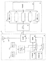
図示のように、アンテナユニット10は伝送線ケーブル14によって受信機12に接続される。アンテナユニットは、従来のGPS受信システムと同様に、衛星や擬似衛星からの距離信号の受信に適したアンテナ18を格納するためのハウジング16を有する。アンテナで受信された信号は前置増幅器20で増幅され、その出力はケーブル14によって受信機12に渡される。
As illustrated, the
受信機12は、伝送線14を介して受信した高周波信号を中間周波信号に変換するためのダウンコンバータ22を含む。次いで、ダウンコンバータ22の出力は複数の相関チャネル241〜24nに渡される。チャネル24はそれぞれ、処理装置26の制御により、特定の信号源(すなわち、従来のシステムにおける衛星や擬似衛星)から送信された信号を復調する。そして、処理装置26は、得られた時間情報を使用して受信機(すなわち、正確にはアンテナ18)の位置を推定する。
The
詳しくは、GPSシステムのような衛星距離システムに使用される構成と同様に、衛星から送られたRF搬送波を変調する際には、その衛星で使用される擬似ランダム符号の複製を各チャネル24に割り当て、チャネルは、その複製を信号に関連付けて、衛星からの信号を復調する。各衛星は、送信された信号を衛星の識別情報や衛星の軌道上の位置などの衛星データを用いて更に変調する。本発明のGPSシステムでは、各ビットの値が0であるか1であるかに応じて擬似ランダム符号を反転または非反転させることにより、このデータが1秒当たり50ビットの速度で送信される。それらのビットは復調処理によって復元され、処理装置26によって使用される。処理装置26は、受信機の位置を計算する際に、それらのビットを衛星からの複製符号距離の時間とともに使用する。
Specifically, similar to the configuration used in a satellite distance system such as a GPS system, when modulating an RF carrier wave transmitted from a satellite, a duplicate of a pseudo-random code used in that satellite is assigned to each
本発明によれば、アンテナハウジング16は、一連の慣性センサ271〜27mの格納にも使用される。これらのセンサは、加速度計、ジャイロなどの任意の組み合わせであってよく、それらの出力を数学的に処理することにより位置情報を生成し、必要であれば更に、速度、加速度、および姿勢などの情報を生成する。それらのセンサの出力は、周回衛星と同じ搬送波周波数を有するRF発生器28から供給されたRF搬送波の変調に使用され、生成された信号はケーブル14を介して受信機12に渡され、そこで処理装置26によりそのタスクに割り当てられたチャネル24によって復調される。
According to the present invention, the
詳しくは、アンテナエンクロージャ16は符号発生器30をさらに含み、符号発生器30は、周回衛星で使用される擬似ランダム符号と同じ長さおよびチップレートを有する一意の(重複のない)擬似ランダム符号を生成する。慣性センサ27の出力は1以上のアナログ/デジタル変換器32によって2値化され、得られた信号は制御式インバータ341〜34Kに供給され、符号発生器30からの擬似ランダム符号の変調に使用される。この変調は、周回衛星で使用される符号がそれらの衛星から送信されるデータで変調されるのと同じ方式で行われる。次いで、インバータの出力は変調器38に供給され、変調器38は、RF発生器38の出力を位相変調する。変調された信号は、信号結合器40で増幅器20の出力と結合される。
Specifically, the
受信機12において、処理装置26のソフトウェア(またはファームウェア)は、センサ27で生成された慣性データに関連する擬似ランダム符号を幾つかのチャネル24に割り当てる。それらのチャネルは通常方式で動作し、それらのデータを有する信号を復調する。その結果、処理装置26は、慣性データだけでなく、衛星から送信された信号から導出されたデータも受信する。よく知られた方式では、衛星信号から導出された位置情報は、慣性データの校正に使用される。そのため、安価で不正確なセンサを使用しても、慣性データの精度は比較的高くなる。
At the
受信機12の動作は、処理装置26に含まれるソフトウェアによって決まる。従って、既存の受信機に変更を加え、適当なソフトウェアを搭載することで、本発明に従った動作をさせることが簡単に可能である。
The operation of the
なお、GPS衛星から送信されるデータのビットレート(50bps)はGPSシステムで使用される。GPS信号を受信するように構成された受信機は、1チャネル当たり500〜1000bps高い速度で受信したデータを復元することができる。本明細書に記載のシステムは、そのようなビットレートを使用することが好ましい。 Note that the bit rate (50 bps) of data transmitted from a GPS satellite is used in the GPS system. A receiver configured to receive GPS signals can recover data received at a rate of 500-1000 bps higher per channel. The systems described herein preferably use such bit rates.
例えば、3軸の角度データおよび加速度データを生成する慣性センサを使用する場合を仮定する。さらに、チャネルの1つに各パラメータが割り当てられ、各パラメータが、4バイトのデータと、ヘッダおよびチェックサム用の2バイトのデータとを有するものと仮定する。その場合、1つのデジタルチャネル当たり6バイト(48ビット)の情報が必要になる。データを50%の効率で圧縮した場合、システムは、データを約40Hzの速度で生成することになる。これは、位置情報や速度情報に依存する大抵の制御システムの必要条件を十分に満たしている。 For example, it is assumed that an inertial sensor that generates three-axis angle data and acceleration data is used. Further assume that each parameter is assigned to one of the channels and each parameter has 4 bytes of data and 2 bytes of data for the header and checksum. In that case, 6 bytes (48 bits) of information per digital channel is required. If the data is compressed with 50% efficiency, the system will generate the data at a rate of about 40 Hz. This fully meets the requirements of most control systems that rely on position and velocity information.
Claims (6)
A)各チャネルが前記距離信号を復調し、該距離信号からデータを復元するように構成された複数のチャネルと、
B)a.各チャネルに対し、そのチャネルで復調すべきソース信号から得られた信号を割り当て、
b.前記距離信号から受信されたデータを処理する制御手段と
を備え、
C)前記複数のチャネルは、(i)一意の擬似ランダム符号と衛星データを使用して前記距離信号を生成する周回衛星から受信機が受信した衛星距離信号、及び(ii)一意の擬似ランダム符号と慣性センサデータを使用して前記距離信号を生成する変調手段から受信機が受信した擬似距離信号を、前記衛星距離信号、及び前記該擬似距離信号の生成に使用される擬似ランダム符号のローカル複製に関連付け、
前記制御手段は、前記チャネルで使用される符号複製を選択することにより前記チャネルを対応する信号源に割り当てる、受信機。A receiver for demodulating and processing a distance signal,
A) a plurality of channels, each channel configured to demodulate the distance signal and recover data from the distance signal;
B) a. For each channel, assign a signal derived from the source signal to be demodulated on that channel,
b. Control means for processing data received from the distance signal ;
With
C) The plurality of channels are: (i) a satellite distance signal received by a receiver from an orbiting satellite that generates the distance signal using a unique pseudo-random code and satellite data; and (ii) a unique pseudo-random code. And the pseudorange signal received by the receiver from the modulation means for generating the distance signal using inertial sensor data, the satellite distance signal, and a local replica of the pseudorandom code used to generate the pseudorange signal. Associated with
The receiver , wherein the control means assigns the channel to a corresponding signal source by selecting a code replica used in the channel.
A)前記距離信号を前記受信機に送信するための前記RFリンクに接続された、前記距離信号を受信するためのアンテナと、
B)慣性データを提供する複数の慣性センサと、
C)RF発生器と、
D)前記RF発生器の出力を前記距離信号が衛星データで変調されるのと同じ方式により前記慣性データで変調することにより擬似距離信号を生成する手段と、
E)前記擬似距離信号を前記RFリンクに接続して前記受信機に送信する手段と
からなるリモート・アンテナ・ユニット。A remote antenna unit connected by an RF link to a receiver for demodulating and processing a distance signal transmitted from an orbiting satellite;
A) an antenna for receiving the distance signal connected to the RF link for transmitting the distance signal to the receiver;
B) a plurality of inertial sensors that provide inertial data;
C) an RF generator;
D) means for generating a pseudorange signal by modulating the output of the RF generator with the inertial data in the same manner that the distance signal is modulated with satellite data;
E) A remote antenna unit comprising: means for connecting the pseudorange signal to the RF link and transmitting the pseudorange signal to the receiver.
A)各チャネルが前記距離信号を復調し、該距離信号から関連データを復元するように構成された複数のチャネルと、
B)前記複数のチャネルに信号を送信するためのRFリンクと、
C)前記距離信号を送信するためのRFリンクに接続された、衛星から距離信号を受信するためのアンテナと、
D)慣性データを提供する複数の慣性センサと、
E)RF発生器と、
F)前記RF発生器の出力を前記距離信号が衛星データで変調されるのと同じ方式により前記慣性データで変調することにより擬似距離信号を生成する手段と、
G)前記擬似距離信号を前記RFリンクに接続して複数のチャネルに送信する手段と
からなる受信機システム。A receiver system for demodulating and processing a distance signal, comprising:
A) a plurality of channels, each channel configured to demodulate the distance signal and recover related data from the distance signal;
B) an RF link for transmitting signals to the plurality of channels;
C) an antenna for receiving a distance signal from a satellite connected to an RF link for transmitting the distance signal;
D) a plurality of inertial sensors that provide inertial data;
E) an RF generator;
F) means for generating a pseudorange signal by modulating the output of the RF generator with the inertial data in the same manner that the range signal is modulated with satellite data;
G) A receiver system comprising: the pseudorange signal connected to the RF link and transmitted to a plurality of channels.
前記距離データから受信した衛星データおよび慣性データを処理する手段と
をさらに含む、請求項4に記載の受信機システム。A control device for assigning to each channel a signal source of a signal to be demodulated in that channel, the control means for assigning the selected channel to a signal source associated with said inertial data;
The receiver system according to claim 4, further comprising means for processing satellite data and inertial data received from the distance data.
前記変調手段は、前記RF発生器の出力を一意の擬似ランダム符号で変調するとともに、該符号を慣性データで変調し、
前記チャネルは、受信機で受信した信号を前記擬似ランダム符号のローカル複製に関連付け、
前記制御装置は、前記チャネルで使用される符号複製を選択することにより前記チャネルを対応する信号源に割り当てる、請求項5に記載の受信機システム。The RF generator has the same frequency as the satellite carrier frequency;
The modulating means modulates the output of the RF generator with a unique pseudo-random code and modulates the code with inertial data;
The channel associates a signal received at a receiver with a local replica of the pseudo-random code;
The receiver system according to claim 5, wherein the controller assigns the channel to a corresponding signal source by selecting a code replica to be used in the channel.
Applications Claiming Priority (2)
| Application Number | Priority Date | Filing Date | Title |
|---|---|---|---|
| US10/365,281 US6750816B1 (en) | 2003-02-12 | 2003-02-12 | Integrated GPS-inertial system |
| PCT/CA2004/000180 WO2004072582A1 (en) | 2003-02-12 | 2004-02-11 | Integrated gps-inertial system |
Publications (2)
| Publication Number | Publication Date |
|---|---|
| JP2006517656A JP2006517656A (en) | 2006-07-27 |
| JP4205129B2 true JP4205129B2 (en) | 2009-01-07 |
Family
ID=32393193
Family Applications (1)
| Application Number | Title | Priority Date | Filing Date |
|---|---|---|---|
| JP2006500443A Expired - Lifetime JP4205129B2 (en) | 2003-02-12 | 2004-02-11 | Integrated GPS inertial system |
Country Status (6)
| Country | Link |
|---|---|
| US (1) | US6750816B1 (en) |
| EP (1) | EP1592946B1 (en) |
| JP (1) | JP4205129B2 (en) |
| AT (1) | ATE464540T1 (en) |
| DE (1) | DE602004026547D1 (en) |
| WO (1) | WO2004072582A1 (en) |
Families Citing this family (50)
| Publication number | Priority date | Publication date | Assignee | Title |
|---|---|---|---|---|
| JP2006033403A (en) * | 2004-07-15 | 2006-02-02 | Honda Motor Co Ltd | Mobile body, information center and mobile communication system |
| US20070032950A1 (en) * | 2005-08-05 | 2007-02-08 | Raven Industries, Inc. | Modular high-precision navigation system |
| US20070282558A1 (en) * | 2006-06-01 | 2007-12-06 | Denso Corporation | Abnormal condition determining system for steering angle sensor |
| EP2193336B1 (en) * | 2007-09-28 | 2013-07-31 | Leica Geosystems AG | A positioning system and method |
| US8442766B2 (en) | 2008-10-02 | 2013-05-14 | Certusview Technologies, Llc | Marking apparatus having enhanced features for underground facility marking operations, and associated methods and systems |
| CA2897462A1 (en) | 2009-02-11 | 2010-05-04 | Certusview Technologies, Llc | Management system, and associated methods and apparatus, for providing automatic assessment of a locate operation |
| FR2953013B1 (en) * | 2009-11-20 | 2012-05-25 | Sagem Defense Securite | NAVIGATION SYSTEM INERTIA / GNSS |
| WO2012021898A2 (en) | 2010-08-13 | 2012-02-16 | Certusview Technologies, Llc | Methods, apparatus and systems for surface type detection in connection with locate and marking operations |
| US9124780B2 (en) | 2010-09-17 | 2015-09-01 | Certusview Technologies, Llc | Methods and apparatus for tracking motion and/or orientation of a marking device |
| US11175375B2 (en) | 2010-11-12 | 2021-11-16 | Position Imaging, Inc. | Position tracking system and method using radio signals and inertial sensing |
| US10416276B2 (en) | 2010-11-12 | 2019-09-17 | Position Imaging, Inc. | Position tracking system and method using radio signals and inertial sensing |
| US8957812B1 (en) | 2010-11-12 | 2015-02-17 | Position Imaging, Inc. | Position tracking system and method using radio signals and inertial sensing |
| US9933509B2 (en) | 2011-11-10 | 2018-04-03 | Position Imaging, Inc. | System for tracking an object using pulsed frequency hopping |
| WO2013071302A1 (en) | 2011-11-10 | 2013-05-16 | Guohua Min | Systems and methods of wireless position tracking |
| US10269182B2 (en) | 2012-06-14 | 2019-04-23 | Position Imaging, Inc. | RF tracking with active sensory feedback |
| US9782669B1 (en) | 2012-06-14 | 2017-10-10 | Position Imaging, Inc. | RF tracking with active sensory feedback |
| US9519344B1 (en) | 2012-08-14 | 2016-12-13 | Position Imaging, Inc. | User input system for immersive interaction |
| US10180490B1 (en) | 2012-08-24 | 2019-01-15 | Position Imaging, Inc. | Radio frequency communication system |
| WO2014093961A1 (en) | 2012-12-15 | 2014-06-19 | Position Imaging, Inc | Cycling reference multiplexing receiver system |
| US9482741B1 (en) | 2013-01-18 | 2016-11-01 | Position Imaging, Inc. | System and method of locating a radio frequency (RF) tracking device using a calibration routine |
| US10856108B2 (en) | 2013-01-18 | 2020-12-01 | Position Imaging, Inc. | System and method of locating a radio frequency (RF) tracking device using a calibration routine |
| US10634761B2 (en) | 2013-12-13 | 2020-04-28 | Position Imaging, Inc. | Tracking system with mobile reader |
| US12000947B2 (en) | 2013-12-13 | 2024-06-04 | Position Imaging, Inc. | Tracking system with mobile reader |
| US9497728B2 (en) | 2014-01-17 | 2016-11-15 | Position Imaging, Inc. | Wireless relay station for radio frequency-based tracking system |
| US10200819B2 (en) | 2014-02-06 | 2019-02-05 | Position Imaging, Inc. | Virtual reality and augmented reality functionality for mobile devices |
| US9766341B2 (en) | 2014-11-13 | 2017-09-19 | Novatel Inc. | GNSS positioning system employing a reconfigurable antenna subsystem |
| US10231337B2 (en) | 2014-12-16 | 2019-03-12 | Inertial Sense, Inc. | Folded printed circuit assemblies and related methods |
| US12079006B2 (en) | 2015-02-13 | 2024-09-03 | Position Imaging, Inc. | Spatial diversity for relative position tracking |
| US11132004B2 (en) | 2015-02-13 | 2021-09-28 | Position Imaging, Inc. | Spatial diveristy for relative position tracking |
| US10642560B2 (en) | 2015-02-13 | 2020-05-05 | Position Imaging, Inc. | Accurate geographic tracking of mobile devices |
| US10324474B2 (en) | 2015-02-13 | 2019-06-18 | Position Imaging, Inc. | Spatial diversity for relative position tracking |
| US10148918B1 (en) | 2015-04-06 | 2018-12-04 | Position Imaging, Inc. | Modular shelving systems for package tracking |
| US10853757B1 (en) | 2015-04-06 | 2020-12-01 | Position Imaging, Inc. | Video for real-time confirmation in package tracking systems |
| US11416805B1 (en) | 2015-04-06 | 2022-08-16 | Position Imaging, Inc. | Light-based guidance for package tracking systems |
| US11501244B1 (en) | 2015-04-06 | 2022-11-15 | Position Imaging, Inc. | Package tracking systems and methods |
| US10444323B2 (en) | 2016-03-08 | 2019-10-15 | Position Imaging, Inc. | Expandable, decentralized position tracking systems and methods |
| US11436553B2 (en) | 2016-09-08 | 2022-09-06 | Position Imaging, Inc. | System and method of object tracking using weight confirmation |
| US10634503B2 (en) | 2016-12-12 | 2020-04-28 | Position Imaging, Inc. | System and method of personalized navigation inside a business enterprise |
| US10634506B2 (en) | 2016-12-12 | 2020-04-28 | Position Imaging, Inc. | System and method of personalized navigation inside a business enterprise |
| US10455364B2 (en) | 2016-12-12 | 2019-10-22 | Position Imaging, Inc. | System and method of personalized navigation inside a business enterprise |
| US11120392B2 (en) | 2017-01-06 | 2021-09-14 | Position Imaging, Inc. | System and method of calibrating a directional light source relative to a camera's field of view |
| US12190542B2 (en) | 2017-01-06 | 2025-01-07 | Position Imaging, Inc. | System and method of calibrating a directional light source relative to a camera's field of view |
| US11047990B2 (en) | 2018-04-24 | 2021-06-29 | Novatel Inc. | Global navigation satellite system (GNSS) antenna data link |
| US10754044B2 (en) | 2018-04-24 | 2020-08-25 | Novatel Inc. | Global navigation satellite system (GNSS) antenna data link |
| MX2021003341A (en) | 2018-09-21 | 2021-08-16 | Position Imaging Inc | Machine-learning-assisted self-improving object-identification system and method. |
| US11089232B2 (en) | 2019-01-11 | 2021-08-10 | Position Imaging, Inc. | Computer-vision-based object tracking and guidance module |
| GB2585221B (en) * | 2019-07-03 | 2023-12-27 | Raytheon Systems Ltd | Global navigation satellite system (gnss) anti-spoofing techniques |
| GB2585222B (en) | 2019-07-03 | 2022-10-12 | Raytheon Systems Ltd | Autonomous vehicles supporting global navigation satellite system (gnss) anti-spoofing |
| US11614545B2 (en) | 2020-03-26 | 2023-03-28 | Novatel Inc. | Systems and methods for utilizing a connector with an external antenna to utilize multifrequency GNSS functionality of a mobile device |
| CN112731476B (en) * | 2020-10-23 | 2023-09-08 | 中国人民解放军63891部队 | GPS satellite M code signal demodulation method based on short code despreading and timing recovery combination |
Family Cites Families (4)
| Publication number | Priority date | Publication date | Assignee | Title |
|---|---|---|---|---|
| JP2900671B2 (en) * | 1991-11-29 | 1999-06-02 | ソニー株式会社 | GPS receiver |
| US6448926B1 (en) * | 1993-11-19 | 2002-09-10 | Itt Manufacturing Enterprises, Inc. | Multi-band, multi-function integrated transceiver |
| US5877725A (en) * | 1997-03-06 | 1999-03-02 | Trimble Navigation Limited | Wide augmentation system retrofit receiver |
| US6520448B1 (en) * | 2001-06-12 | 2003-02-18 | Rockwell Collins, Inc. | Spinning-vehicle navigation using apparent modulation of navigational signals |
-
2003
- 2003-02-12 US US10/365,281 patent/US6750816B1/en not_active Expired - Lifetime
-
2004
- 2004-02-11 AT AT04709965T patent/ATE464540T1/en not_active IP Right Cessation
- 2004-02-11 DE DE602004026547T patent/DE602004026547D1/en not_active Expired - Lifetime
- 2004-02-11 WO PCT/CA2004/000180 patent/WO2004072582A1/en not_active Ceased
- 2004-02-11 JP JP2006500443A patent/JP4205129B2/en not_active Expired - Lifetime
- 2004-02-11 EP EP04709965A patent/EP1592946B1/en not_active Expired - Lifetime
Also Published As
| Publication number | Publication date |
|---|---|
| WO2004072582A1 (en) | 2004-08-26 |
| JP2006517656A (en) | 2006-07-27 |
| EP1592946B1 (en) | 2010-04-14 |
| EP1592946A1 (en) | 2005-11-09 |
| US6750816B1 (en) | 2004-06-15 |
| DE602004026547D1 (en) | 2010-05-27 |
| ATE464540T1 (en) | 2010-04-15 |
Similar Documents
| Publication | Publication Date | Title |
|---|---|---|
| JP4205129B2 (en) | Integrated GPS inertial system | |
| AU667492B2 (en) | GPS tracking system | |
| JP5440894B2 (en) | Position information providing system and indoor transmitter | |
| EP2487508B1 (en) | Positional information transmitter | |
| JP5374703B2 (en) | Position information providing system and indoor transmitter | |
| EP2618182B1 (en) | Location information providing device | |
| CN101627315B (en) | Determining position without current broadcast ephemeris | |
| US5502446A (en) | GPS-based automatic target reporting and finding network and components | |
| TWI504917B (en) | A navigation signal transmission device, a navigation signal transmission method, and a location information providing device | |
| US7904243B2 (en) | Real-time data aiding for enhanced GPS performance | |
| EP0250211A3 (en) | Codeless gps sonde | |
| WO2008097651A1 (en) | Transmission of information to a system utilizing a gps device | |
| Suzuki et al. | Evaluation of precise point positioning using MADOCA-LEX via Quasi-Zenith satellite system | |
| CN113514857B (en) | Pseudo-satellite message generation method, device, computer equipment and storage medium | |
| JPS61235776A (en) | Position measurement system | |
| Pabst | Development and Testing of LoRa Technology for Satellite Communications | |
| JPH05218932A (en) | Satellite communication equipment |
Legal Events
| Date | Code | Title | Description |
|---|---|---|---|
| A131 | Notification of reasons for refusal |
Free format text: JAPANESE INTERMEDIATE CODE: A131 Effective date: 20080520 |
|
| A521 | Request for written amendment filed |
Free format text: JAPANESE INTERMEDIATE CODE: A523 Effective date: 20080820 |
|
| TRDD | Decision of grant or rejection written | ||
| A01 | Written decision to grant a patent or to grant a registration (utility model) |
Free format text: JAPANESE INTERMEDIATE CODE: A01 Effective date: 20080916 |
|
| A01 | Written decision to grant a patent or to grant a registration (utility model) |
Free format text: JAPANESE INTERMEDIATE CODE: A01 |
|
| A61 | First payment of annual fees (during grant procedure) |
Free format text: JAPANESE INTERMEDIATE CODE: A61 Effective date: 20081015 |
|
| FPAY | Renewal fee payment (event date is renewal date of database) |
Free format text: PAYMENT UNTIL: 20111024 Year of fee payment: 3 |
|
| R150 | Certificate of patent or registration of utility model |
Ref document number: 4205129 Country of ref document: JP Free format text: JAPANESE INTERMEDIATE CODE: R150 Free format text: JAPANESE INTERMEDIATE CODE: R150 |
|
| FPAY | Renewal fee payment (event date is renewal date of database) |
Free format text: PAYMENT UNTIL: 20121024 Year of fee payment: 4 |
|
| R250 | Receipt of annual fees |
Free format text: JAPANESE INTERMEDIATE CODE: R250 |
|
| FPAY | Renewal fee payment (event date is renewal date of database) |
Free format text: PAYMENT UNTIL: 20121024 Year of fee payment: 4 |
|
| FPAY | Renewal fee payment (event date is renewal date of database) |
Free format text: PAYMENT UNTIL: 20131024 Year of fee payment: 5 |
|
| R250 | Receipt of annual fees |
Free format text: JAPANESE INTERMEDIATE CODE: R250 |
|
| R250 | Receipt of annual fees |
Free format text: JAPANESE INTERMEDIATE CODE: R250 |
|
| R250 | Receipt of annual fees |
Free format text: JAPANESE INTERMEDIATE CODE: R250 |
|
| R250 | Receipt of annual fees |
Free format text: JAPANESE INTERMEDIATE CODE: R250 |
|
| R250 | Receipt of annual fees |
Free format text: JAPANESE INTERMEDIATE CODE: R250 |
|
| R250 | Receipt of annual fees |
Free format text: JAPANESE INTERMEDIATE CODE: R250 |
|
| R250 | Receipt of annual fees |
Free format text: JAPANESE INTERMEDIATE CODE: R250 |
|
| R250 | Receipt of annual fees |
Free format text: JAPANESE INTERMEDIATE CODE: R250 |
|
| R250 | Receipt of annual fees |
Free format text: JAPANESE INTERMEDIATE CODE: R250 |
|
| R250 | Receipt of annual fees |
Free format text: JAPANESE INTERMEDIATE CODE: R250 |
|
| R250 | Receipt of annual fees |
Free format text: JAPANESE INTERMEDIATE CODE: R250 |
|
| R250 | Receipt of annual fees |
Free format text: JAPANESE INTERMEDIATE CODE: R250 |
|
| EXPY | Cancellation because of completion of term |