JP4202111B2 - Tuner - Google Patents
Tuner Download PDFInfo
- Publication number
- JP4202111B2 JP4202111B2 JP2002370493A JP2002370493A JP4202111B2 JP 4202111 B2 JP4202111 B2 JP 4202111B2 JP 2002370493 A JP2002370493 A JP 2002370493A JP 2002370493 A JP2002370493 A JP 2002370493A JP 4202111 B2 JP4202111 B2 JP 4202111B2
- Authority
- JP
- Japan
- Prior art keywords
- data
- storage unit
- address
- basic period
- sample data
- Prior art date
- Legal status (The legal status is an assumption and is not a legal conclusion. Google has not performed a legal analysis and makes no representation as to the accuracy of the status listed.)
- Expired - Fee Related
Links
Images


Classifications
-
- G—PHYSICS
- G10—MUSICAL INSTRUMENTS; ACOUSTICS
- G10G—REPRESENTATION OF MUSIC; RECORDING MUSIC IN NOTATION FORM; ACCESSORIES FOR MUSIC OR MUSICAL INSTRUMENTS NOT OTHERWISE PROVIDED FOR, e.g. SUPPORTS
- G10G7/00—Other auxiliary devices or accessories, e.g. conductors' batons or separate holders for resin or strings
- G10G7/02—Tuning forks or like devices
Landscapes
- Physics & Mathematics (AREA)
- Engineering & Computer Science (AREA)
- Acoustics & Sound (AREA)
- Multimedia (AREA)
- Auxiliary Devices For Music (AREA)
Description
【0001】
【発明の属する技術分野】
この発明は各種の楽器の音が正しく標準ピッチに調律されているか否かを測定し、その測定結果を表示器に表示し、各楽器の音の周波数を正しい状態に調律することに用いられるチューナに関し、特に応答速度を高速化し、音の周波数変化を忠実に表示することができるチューナを提供しようとするものである。
【0002】
【従来の技術】
従来より各種のチューナが提案されている(特許文献1〜4)。
図8に現在市販されている一般的なチューナの電気的な構成を示す。調律すべき楽器の音をマイクロホン1で捉え、電気信号Sg(図9A参照)に変換する。マイクロホン1から出力された電気信号Sgは増幅器2で増幅される。増幅器2は飽和増幅器とされ、入力された楽器音の電気信号を短形波SP(図9B)になるまで飽和増幅する。
増幅器2から出力される短形波SPはマイクロコンピュータ10に入力される。マイクロコンピュータ10には入力される短形波SPのゼロクロス点b1、b2、b3…のタイミングデータを取得するサンプリング手段11と、一定速度のクロックを計数するカウンタ12と、サンプリング手段11で取得したサンプルデータを格納するデータ格納部13と、このデータ格納部13に格納したサンプルデータを使って入力された短形波SPの基本周期を抽出する基本周期抽出手段14と、基本周期抽出手段14で抽出した基本周期に従って入力された楽器音の音名を判別する音名判別手段15と、入力された楽器音の音名で決定される標準ピッチと入力された楽器音とのピッチ誤差を算出するピッチ誤差算出手段16とが設けられる。
【0003】
音名判別手段15の音名判別結果とピッチ誤差算出手段16の算出結果はマイクロコンピュータ10の外部に設けられた音名表示器17とピッチ誤差表示器18に出力され、判別結果と算出結果を表示する。
サンプリング手段11は、短形波SPのゼロックス点b1、b2、b3…を検出するゼロクロス検出手段11Aと、このゼロクロス検出手段11Aがゼロクロス点を検出した時点の時間軸データをラッチするデータラッチ手段11Bとによって構成される。カウンタ12は既知の周波数を持つクロックを計数し、初期値「00…0」からフルカウント「FF…F」までの間の計数値を時間の経過に従って出力する動作を繰返す。
【0004】
データラッチ手段11Bはゼロクロス検出手段11Aが短形波のゼロクロス点b1、b2、b3…を検出する毎にカウンタ12の計数値C1、C2、C3…を読み取ってサンプルデータとしてラッチしサンプリングする。
データラッチ手段11Bがサンプリングしたサンプルデータをデータ格納部13に順次取り込み、取り込んだ各サンプルデータの時刻から時間間隔を求めることによりゼロクロス点b1、b2、b3…の相互の間の時間間隔を求めることができる。
基本周期抽出手段14はデータ格納部13に格納した複数のサンプルデータの相互の時間間隔を計算し、互に等しい時間間隔を持つ最長の時間間隔を求め、その時間間隔を入力中の楽器音の基本周期として抽出する。基本周期抽出手段14が基本周期を抽出するには入力される楽器音の少なくとも2周期分に相当する時刻データがデータ格納部13に格納されていることが条件とされる。
【0005】
【特許文献1】
実用新案登録第2585225号明細書
【特許文献2】
特許第2681432号明細書
【特許文献3】
特許第3011314号明細書
【特許文献4】
実用新案登録第2594264号明細書
【0006】
【発明が解決しようとする課題】
従来のチューナでは上述したように、基本周期抽出手段14はデータ格納部13に所定個以上のサンプルデータが格納されていないと、入力されている楽器音の基本周期を抽出することができない。データ格納部13に所定個数のサンプルデータを取り込むには入力中の楽器音の少なくとも2周期に相当する時間が必要となり、そのデータ取得時間が経過してから基本周期の抽出処理を実行し、基本周期抽出後に音名及びピッチ誤差を算出するから、データの取得から算出結果を表示するまでの時間が長く掛かる欠点がある。
【0007】
図9にその様子を示す。図中T1はサンプルデータとして時刻データC1、C2、C3…を取り込むデータ取得時間、T2は基本周期抽出及び音名、ピッチ誤差算出期間を示す。尚、期間T2の内訳はその大部分の時間は基本周期抽出処理に使われ、音名判別及びピッチ誤差の算出時間はわずかであるから、以下ではT2を基本周期抽出期間と称する基本周期抽出期間T2が終了した時点で表示の更新が行われる。表示の更新が実行された後、再び期間T1を掛けて最新のデータを取得し、取得したデータに基づいて基本波抽出処理を実行することを繰返す。従って、従来のチューナでは表示の更新周期はT1+T2=T3となる。表示更新周期T3が長いと、入力されている楽器音の周波数が変化しても、測定の時間間隔が長いために周波数が変化していく様子を連続的に追従して測定し、その測定結果を表示することができない欠点がある。
【0008】
例えば、ギターの奏法の中にビブラート奏法がある。演奏者はビブラート奏法で音の周波数の揺れ幅を予め知ることができると、最適な演奏操作の感触を習得することができるから、ビブラートを掛けた場合、その音の周波数の揺れ幅が分かると都合がよい。然し乍ら、従来のチューナの技術ではリアルタイムで音の周波数の揺れを測定し、表示することはできない。また、ビブラートに限らず他の奏法でも周波数がズレていく様子を測定し、表示することができると都合がよい。また、調律中に調律操作に伴って周波数が高い方、又は低い方にずれていく様子が表示できると、調律を容易に行うことができる。
【0009】
表示の更新周期を短くするにはデータ取得時間T1と基本周期算出処理期間T2を短くすればよいが、データの取り込み期間T1は上述したように調律しようとする音の基本周期で決まるため、調律しようとする音の周期の2周期より短くすることはできない。また、基本周期算出処理に要する時間T2はマイクロコンピュータ10の演算処理速度で決定されるが、限度以上に短くすることはできない。
この発明の目的は比較的簡素な構成で表示の更新周期を短くし、入力される音の周波数の変化をリアルタイムに表示することができるチューナのデータ処理方法及びこのデータ処理方法とこのデータ処理方法を用いたチューナを提案しようとするものである。
【0010】
【課題を解決するための手段】
この発明の請求項1では、調律しようとする楽器音に対応する電気信号がゼロクロスしたことを検出するゼロクロス検出手段と、このゼロクロス検出手段がゼロクロスしたことを検出する毎に、基準のタイミングから一定速度で計数動作しているカウンタの計数値を読み取るラッチ回路とによって構成するサンプリング手段と、このサンプリング手段でサンプリングしたサンプルデータを所定個格納するデータ格納部と、このデータ格納部に、サンプリング手段でサンプリングしたサンプルデータを書き込む書き込み制御部であって、データ格納部に格納されている所定個のサンプルデータの中の最古のサンプルデータに代えて最新のサンプルデータを書き込む制御を行う書込制御手段と、データ格納部に格納されている所定個のサンプルデータを読み込んで、これら所定個のサンプルデータを用いて、楽器音の基本周期を抽出し、抽出処理が終了する毎に直ちにデータ格納部に格納されている所定個のサンプルデータを用いて、楽器音の基本周期を抽出する動作を繰返す基本周期抽出手段と、この基本周期抽出手段が抽出した基本周期と標準ピッチとを比較し、楽器音の音名を判別、及び標準ピッチからの誤差値を算出する音名判別手段及びピッチ誤差算出手段と、この音名判別手段及びピッチ誤差算出手段が算出した結果を表示する音名表示器及びピッチ誤差表示器と、によって構成することを特徴とするチューナを提案する。
【0011】
この発明の請求項2では、調律しようとする楽器音に対応する電気信号をA/D変換するサンプリング手段と、このサンプリング手段でサンプリングしたサンプルデータを所定個格納するデータ格納部と、このデータ格納部に、サンプリング手段でサンプリングしたサンプルデータを書き込む書き込み制御部であって、データ格納部に格納されている所定個のサンプルデータの中の最古のサンプルデータに代えて最新のサンプルデータを書き込む制御を行う書込制御手段と、データ格納部に格納されている所定個のサンプルデータを読み込んで、これら所定個のサンプルデータを用いて、楽器音の基本周期を抽出し、抽出処理が終了する毎に直ちにデータ格納部に格納されている所定個のサンプルデータを用いて、楽器音の基本周期を抽出する動作を繰返す基本周期抽出手段と、この基本周期抽出手段が抽出した基本周期と標準ピッチとを比較し、楽器音の音名を判別、及び標準ピッチからの誤差値を算出する音名判別手段及びピッチ誤差算出手段と、この音名判別手段及びピッチ誤差算出手段が算出した結果を表示する音名表示器及びピッチ誤差表示器と、によって構成することを特徴とするチューナを提案する。
【0012】
この発明の請求項3では、請求項1記載のチューナにおいて、書込制御手段は、データ格納部に格納されている複数のデータの中の最古のデータが記憶されているアドレスを記憶するポインタを有し、このポインタが指し示すアドレスに最新のデータを書き込むと共に、ポインタの値を1アドレス分移動させる制御を行うことを特徴とするチューナを提案する。
この発明の請求項4では、請求項1記載のチューナにおいて、書込制御手段はデータ格納部に格納されている複数のデータの各アドレスを全て1アドレス分移動させるアドレス移動手段と、このアドレス移動手段で移動したアドレスの中の空きアドレスに最新のサンプルデータを書き込む制御を行うことを特徴とするチューナを提案する。
この発明の請求項5では、請求項2記載のチューナにおいて、書込制御手段は、データ格納部に格納されている複数のデータの中の最古のデータが記憶されているアドレスを記憶するポインタを有し、このポインタが指し示すアドレスに最新のデータを書き込むと共に、ポインタの値を1アドレス分移動させる制御を行うことを特徴とするチューナを提案する。
【0013】
この発明の請求項6では、請求項2記載のチューナにおいて、書込制御手段はデータ格納部に格納されている複数のデータの各アドレスを全て1アドレス分移動させるアドレス移動手段と、このアドレス移動手段で移動したアドレスの中の空きアドレスに最新のサンプルデータを書き込む制御を行うことを特徴とするチューナを提案する。
この発明の請求項7では、請求項1、3、4記載のチューナの何れかにおいて、サンプリング手段がサンプル動作したことを検出して、基本周期抽出手段の動作に割込みを掛け、割り込み期間中に書込制御手段を起動させ、ラッチ回路に記憶されている時刻データをデータ格納部に書き込む動作を実行することを特徴とするチューナを提案する。
この発明の請求項8では、請求項1、3、4記載のチューナの何れかにおいて、基本周期抽出処理手段に、ラッチ回路に記憶されている時刻データが更新されたことを検出する手段を設け、基本周期抽出処理中にラッチ回路の時刻データが更新されていることを検出すると書込制御手段を起動させ、ラッチ回路に記憶されている時刻データをデータ格納部に書き込む動作を実行することを特徴とするチューナを提案する。
【0014】
作用
この発明によるチューナのデータ処理方法によれば、所定個のサンプルデータの中の最古のサンプルデータを消去し、最古のサンプルデータに代えて最新のサンプルデータをデータ格納部に書き込む方法で、所定個のサンプルデータの内容を更新するから、データ格納部には常に各時点における最新のサンプルデータを所定個分用意しておくことができる。この結果、基本周期抽出手段は前回の基本周期抽出処理が終了すると直ちに次の基本周期抽出処理を実行することができる。
この結果、この発明によれば基本周期抽出処理は実質的に常時連続的に実行することができ、その処理結果を順次、音名判別手段及びピッチ誤差算出手段に送り込むことができる。この結果、表示の更新は基本周期抽出処理の時間間隔で更新され、従来より数倍速い周期で表示の内容が更新され、音の周波数の変化をリアルタイムで表現することができる。
【0015】
【発明の実施の形態】
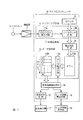
図1にこの発明によるチューナの一実施例を示す。図8と対応する部分には同一符号を付して示す。この発明の特徴とする構成はサンプリング手段11を構成するデータラッチ回路11Bとデータ格納部13との間に書込制御手段20を設けた点にある。尚、その他に図8と異なる点はデータ格納部13の内部をデータ取込用のメモリ13Aと、データ処理用のバッファメモリ13Bに分けた構成とした点である。この構成の違いは基本周期抽出部14が、基本周期抽出処理のために、メモリに格納しているサンプルデータを利用して基本周期検出処理を実行している最中に、データの書き込みが行われることを避けるために、基本周期抽出処理専用にバッファメモリ13Bを設けた構成としたものである。
【0016】
書込制御手段20は例えばゼロクロス検出手段11Aが短形波のゼロクロス点を検出すると、その検出に同期してこの実施例では割込信号を発生させ、この割込信号によりマイクロコンピュータは書込制御手段20を起動させ、データラッチ手段11Bにラッチしたデータをメモリ13Aに書き込む動作を実行させる。メモリ13Aへの書き込みは以下の如くして実行される。図2にメモリ13Aの内部の様子を示す。メモリ13Aにはアドレスが0〜Nまで用意される。各アドレスにポインタ記憶領域とサンプルデータ記憶領域が設けられる。ポインタ記憶領域に次回サンプルデータを書き込むアドレスを指示するデータ、例えば“1”が書き込まれる。
【0017】
割込信号が発生してデータラッチ手段11Bにカウンタ12から時刻データが読み込まれると、書込制御手段20はこの時刻データをサンプルデータとしてメモリ13Aのポインタで指示されたアドレスに書き込む。書き込みが終了すると、ポインタのアドレスは+1されて次のアドレスのポインタに“1”が書き込まれる。ポインタがアドレスNまで達すると、次の書き込みアドレスはアドレス0が指定される。
このように、書込アドレスを+1(−1でもよい)ずつずらして循環させることにより、書き込みを行うアドレスに格納されているデータは過去最古のデータとなり、0〜Nまでのアドレスには常に最新のN個のデータが格納された状態となる。メモリ13Aへの書き込み動作を割込みで実行させることにより、基本周期抽出手段14が基本周期抽出処理を実行している状態でも割込みによりわずかな時間を作ってメモリ13Aへのデータの書き込みが実行される。
【0018】
従って、この発明では基本周期抽出手段14が入力されている楽器音の基本周期を抽出処理している期間でもメモリ13Aには新しいサンプルデータが書き込まれN個のデータは時々刻々最新のデータに更新される。
基本周期抽出手段14が基本周期抽出処理を完了すると、抽出した基本周期データが音名判別手段15とピッチ誤差算出手段16に渡され、基本周期データに従って入力されている音の音名を判別すると共に、その音名の標準ピッチからの誤差を算出しての結果を音名表示器17及びピッチ誤差表示器18に表示する。
上述した一連の動作を実行するプログラムの概要を図3に示す。
【0019】
プログラムはデータ格納部13と、基本周期抽出手段14と、音名判別手段15と、ピッチ誤差算出手段16と、音名表示器17と、ピッチ誤差表示器18を制御するメインルーチン(図3A)と、このメインルーチンを実行中にゼロクロス検出手段11Aがゼロクロスを検出し、割込信号を発信した場合に実行する割込処理ルーチン(図3B)とが存在する。
メインルーチンのステップSP1でメモリ13Aに所定個のデータが存在するか否かを判定する。NOであれば、ステップSP1を繰返す。
YESであればステップSP2に進む。
【0020】
ステップSP2ではメモリ13Aからバッファメモリ13Bにデータを転送する。この転送の際にデータ転送手段13Cはメモリ13Aのポインタに“1”が書き込まれているアドレスからアドレスNまでのデータを読み出し、そのデータをバッファメモリ13Bに転送すると共に、次にアドレス0〜ポインタに“1”が書き込まれているアドレスの一つ手前のアドレスのデータを読み出してバッファメモリ13Bに転送する。バッファメモリ13Bでは転送されて来たデータの中の最初に送られて来たデータを最古のデータと判定して、このデータを例えばアドレスNからアドレス0に向って順次新しいデータを格納して並べ換えを行なう。このように並べ換えを行なうことによってアドレスの順番にデータの取得時刻が降順又は昇順に並べられ、基本周期抽出処理が容易に行なえるようにしている。
【0021】
データの転送が終了すると、ステップSP3に進む。
ステップSP3ではバッファメモリ13Bに格納されたデータを用いて基本周期抽出処理が実行される。基本周期が抽出されると、ステップSP4に進む。
ステップSP4ではステップSP3で抽出した基本周期を用いて入力中の音の音名を判別し、その音名で決まる標準ピッチからのピッチ誤差値を算出する。音名の判別とピッチ誤差が算出されると、ステップSP5に進む。
ステップSP5では音名判別・ピッチ誤差算出ステップSP4で判別された音名とピッチ誤差値を音名表示器17とピッチ誤差表示器18に入力し、表示の内容を更新する。表示の内容が更新されると、ステップSP1に戻り、ステップSP1からステップSP5までの動作を繰返す。
【0022】
以上のメインルーチンを実行中にゼロックロス検出手段11Aがゼロクロス点を検出すると割込信号が発生し、図3Bに示す割込処理ルーチンが実行される。割込処理ルーチンはステップ6でラッチ回路11Bに格納されているデータをメモリ13Aに書き込み、書き込みが完了した時点でステップSP7でポインタのアドレスを+1(−1でもよい)してメインルーチンに戻る。
以上説明したこの発明によるデータ処理方法を利用することにより、図4に示すように、初期状態からN個のサンプルデータがメモリ13Aに格納されるまでの間は別として、一旦バッファメモリ13BにN個のサンプルデータが格納されると、それ以後、基本周期抽出手段14は基本周期抽出処理(音名判別及びピッチ誤差算出処理も含む)を終了する毎に、直ちに次の基本周期抽出処理を実行することができる。従って、基本周期抽出処理は跡切れることなく、実質的にはほぼ連続して実行され、表示器17と18には基本周期抽出処理の期間T2を周期として音名算出結果とピッチ誤差算出結果とが与えられ、従来と比較して数倍の繰返し速度で表示内容を更新することができる。この結果、入力中の楽器音の周波数が変化すると、その変化する様子をリアルタイムでピッチ誤差表示器18に表示することができる。
【0023】
図1に示した実施例では、メモリ13Aにポインタを設けポインタが指示するアドレスに次のサンプルデータの書き込みを実行し、メモリ13Aに記録されている最古のデータのアドレスに最新のデータを書き込んで常時N個のデータを最新状態に更新する方法を説明したが、図5に示すようにFIFOと呼ばれるメモリ形式で同様の方法を実行することができる。FIFOによれば入力側の先頭アドレス0にサンプルデータを書き込むと、過去に書き込まれているデータは1アドレスずつ出力側のアドレスNに向って移動する。最も古いデータが出力側のアドレスNに達すると、次の書き込みではアドレスNに格納されていたデータは外部に排出され、メモリ13Aから消去され、入力側のアドレス0に最新のデータが書き込まれる。従って、この場合には書込制御手段20は存在するデータのアドレスを+1(又は−1)してデータが書き込まれているアドレスを移動させると共に入力側のアドレス0に最新のデータを書き込めばよい。このようにFIFO形式のメモリを用いても図1と同様のデータ処理を実行することができ、図1の実施例と同様の作用効果を得ることができる。
【0024】
図6はこの発明の他の実施例を説明するためのフロチャートを示す。この実施例では基本周期抽出手段14における基本周期抽出処理ステップSP3を複数の処理ステップA、B、Cに分割し、各処理ステップA、B、Cが終了する毎にサブルーチンに至る。データが更新されていない場合はステップSP6から直接メインルーチンに戻る。
音名判別・ピッチ誤差算出ステップSP4でも処理ステップを複数の処理ステップD、E、Fに分割し、各処理ステップD、E、Fが終了する毎にサブルーチンを実行させ、データの値が更新されている場合は、そのデータをメモリ13Aに書き込む動作を実行させる構成としたものである。このように構成しても図1と同様の作用効果を得ることができる。
【0025】
図7はこの発明の更に他の実施例を示す。この実施例ではサンプリング手段11をA/D変換器11Cで構成した場合を示す。従って、この場合には増幅器2はリニア増幅器とされ楽器音を歪みなく増幅してA/D変換器11Cに与える。A/D変換器11Cでは楽器音信号をA/D変換し、そのA/D変換したデジタルの波形データをデータ格納部13を構成する波形メモリ13Dに格納する。
基本周期抽出手段14が基本周期抽出処理を終了すると、データ転送手段13Cを起動し、波形メモリ13Dに記憶した波形データをバッファメモリ13Eに転送する。基本周期抽出手段14は例えば前回転送された波形データと今回転送された波形データとを一方の波形データの位相をずらしながら比較し、波形が一致する位相を検出する。初期の位相一致状態から次に波形一致するまでの位相量を検出することにより波形の一波長に相当する位相量を検出することができる。この波形の一波長から信号の基本周期を抽出することができる。
【0026】
基本周期抽出手段14が基本周期の抽出処理を実行している期間にA/D変換器11Cは引き続いて入力される楽器音の波形をA/D変換し、そのA/D変換した波形データを波形メモリ13Dに格納している。
基本周期抽出手段14が基本周期抽出処理を完了すると、データ転送13Cを起動し、次の波形データをバッファメモリ13Eに転送する。従って、この実施例でも音名表示器17及びピッチ誤差表示器18の更新は図1に示した実施例と同様に基本周期抽出手段14の処理の時間で決まる周期で繰返され、高速度に表示内容が更新される。この結果図1に示した実施例と同様の作用効果を得ることができる。
【0027】
【発明の効果】
以上説明したように、この発明によれば予め所定個数のサンプルデータが存在しないと、基本周期の抽出処理を実行することができないチューナにおいて、基本周期の抽出処理期間中もサンプルデータを取り込む動作を実行し、メモリ13A(図1)又は13D(図7)に常に最新のサンプルデータを格納した状態を得ることができる。この結果、基本周期抽出手段14が基本周期の抽出処理が完了する毎に次の基本周期の抽出処理を実行することができる。この結果、音名判別とピッチ誤差の算出結果を基本周期抽出手段の処理時間の周期で出力することができ、この基本周期抽出処理の周期で表示内容を更新することができるから、調律中に楽器音の周波数が変化しても、その周波数の変化をリアルタイムで表示器に表示することができる。
この結果、例えばビブラートを演奏した場合の周波数のずれ幅等、演奏者が知りたい情報を演奏者に知らせることができ、その効果は実用に供して頗る大である。
【図面の簡単な説明】
【図1】この発明の一実施例を説明するためのブロック図。
【図2】図1に示した実施例用いたメモリ13Aの制御の様子を説明するための図。
【図3】図1に示した実施例の動作を説明するためのフローチャート。
【図4】図1に示した実施例の動作を説明するためのタイミングチャート。
【図5】この発明の変形実施例を説明するための要部のブロック図。
【図6】この発明の更に他の変形実施例を説明するためのフロチャート。
【図7】この発明の更に他の実施例を説明するためのブロック図。
【図8】従来のチューナの電気的な構造を説明するためのブロック図。
【図9】従来のチューナの動作を説明するためのタイミングチャート。
【図10】図9と同様のタイミングチャート。
【符号の説明】
1 マイクロホン 13A メモリ
2 増幅器 13B バッファメモリ
10 マイクロコンピュータ 14 基本周期抽出手段
11 サンプリング手段 15 音名判別手段
11A ゼロクロス検出手段 16 ピッチ誤差算出手段
11B データラッチ手段 17 音名表示器
12 カウンタ 18 ピッチ誤差表示器
13 データ格納部 20 書込制御手段[0001]
BACKGROUND OF THE INVENTION
This invention measures whether or not the sounds of various musical instruments are correctly tuned to a standard pitch, displays the measurement results on a display, and is used to tune the frequency of the sound of each musical instrument to the correct state. In particular, an object of the present invention is to provide a tuner capable of increasing the response speed and faithfully displaying a change in sound frequency.
[0002]
[Prior art]
Conventionally, various tuners have been proposed (
FIG. 8 shows an electrical configuration of a general tuner currently on the market. The sound of the instrument to be tuned is captured by the
The short wave SP output from the
[0003]
The pitch name discrimination result of the pitch name discrimination means 15 and the calculation result of the pitch error calculation means 16 are output to the pitch name display 17 and the pitch error display 18 provided outside the microcomputer 10, and the discrimination result and the calculation result are displayed. indicate.
The sampling means 11 includes a zero cross detection means 11A for detecting the Xerox points b1, b2, b3... Of the short wave SP, and a data latch means 11B for latching time axis data at the time when the zero cross detection means 11A detects the zero cross point. It is comprised by. The counter 12 counts a clock having a known frequency and repeats an operation of outputting a count value between the initial value “00... 0” and the full count “FF.
[0004]
The data latch means 11B reads the count values C1, C2, C3... Of the
The sample data sampled by the data latch means 11B is sequentially taken into the
The basic period extraction means 14 calculates the mutual time interval of the plurality of sample data stored in the
[0005]
[Patent Document 1]
Utility Model Registration No. 2585225 [Patent Document 2]
Japanese Patent No. 2681432 [Patent Document 3]
Japanese Patent No. 3011314 [Patent Document 4]
Utility Model Registration No. 2594264 Specification [0006]
[Problems to be solved by the invention]
As described above, in the conventional tuner, the basic
[0007]
This is shown in FIG. In the figure, T1 represents a data acquisition time for taking in time data C1, C2, C3... As sample data, and T2 represents basic period extraction, pitch name, and pitch error calculation period. The breakdown of the period T2 is mostly used for the basic period extraction process, and the calculation time of the pitch name discrimination and pitch error is very short. Therefore, in the following, the basic period extraction period in which T2 is referred to as the basic period extraction period. The display is updated when T2 ends. After the display is updated, the latest data is acquired again by multiplying the period T1, and the fundamental wave extraction process is repeated based on the acquired data. Therefore, in the conventional tuner, the display update cycle is T1 + T2 = T3. When the display update period T3 is long, even if the frequency of the input instrument sound changes, the measurement time interval is long, and the state of frequency change is continuously tracked and measured. There is a disadvantage that can not be displayed.
[0008]
For example, there is a vibrato technique among the guitar techniques. If the performer knows the amplitude of the frequency of the sound in advance with the vibrato technique, he can learn the optimal feel of the performance operation. convenient. However, the conventional tuner technology cannot measure and display the fluctuation of the sound frequency in real time. In addition, it is convenient to be able to measure and display the frequency shift not only with vibrato but also with other playing methods. In addition, tuning can be easily performed when a state in which the frequency is shifted to a higher or lower frequency in accordance with the tuning operation can be displayed.
[0009]
In order to shorten the display update period, the data acquisition time T1 and the basic period calculation processing period T2 may be shortened. However, since the data acquisition period T1 is determined by the basic period of the sound to be tuned as described above, It cannot be shorter than two cycles of the sound to be attempted. The time T2 required for the basic period calculation process is determined by the calculation processing speed of the microcomputer 10, but cannot be made shorter than the limit.
SUMMARY OF THE INVENTION An object of the present invention is to provide a tuner data processing method, a data processing method, and a data processing method capable of displaying a change in frequency of an input sound in real time by shortening a display update period with a relatively simple configuration. I am going to propose a tuner using.
[0010]
[Means for Solving the Problems]
According to the first aspect of the present invention, the zero cross detecting means for detecting that the electric signal corresponding to the musical instrument sound to be tuned has zero-crossed, and every time the zero-cross detecting means detects that the zero cross has been detected, it is constant from the reference timing. A sampling means comprising a latch circuit that reads the count value of the counter that is counting at a speed, a data storage section for storing a predetermined number of sample data sampled by the sampling means, and a sampling means for storing data in the data storage section A write control unit for writing sampled sample data, the write control unit performing control for writing the latest sample data instead of the oldest sample data in a predetermined number of sample data stored in the data storage unit And a predetermined number of sample data stored in the data storage unit. The basic period of the instrument sound is extracted using these predetermined number of sample data, and every time the extraction process is completed, the predetermined number of sample data stored in the data storage unit is used immediately to complete the musical instrument. The basic period extraction means that repeats the operation for extracting the basic period of the sound, the basic period extracted by the basic period extraction means and the standard pitch are compared, the pitch name of the instrument sound is determined, and the error value from the standard pitch is calculated. A tuner comprising: a pitch name determination unit and a pitch error calculation unit to be calculated; and a pitch name display and a pitch error display for displaying results calculated by the pitch name determination unit and the pitch error calculation unit Propose.
[0011]
According to a second aspect of the present invention, a sampling means for A / D converting an electrical signal corresponding to an instrument sound to be tuned, a data storage section for storing a predetermined number of sample data sampled by the sampling means, and this data storage A write control unit for writing sample data sampled by the sampling means to the unit, and a control for writing the latest sample data in place of the oldest sample data in a predetermined number of sample data stored in the data storage unit A reading control means for performing the reading, and reading a predetermined number of sample data stored in the data storage unit, extracting a basic period of the instrument sound using the predetermined number of sample data, and each time the extraction process is completed The basic period of the instrument sound is extracted immediately using a predetermined number of sample data stored in the data storage unit. A basic period extracting means for repeating the operation, a pitch name discriminating means for comparing the basic period extracted by the basic period extracting means with the standard pitch, discriminating the pitch name of the instrument sound, and calculating an error value from the standard pitch; There is proposed a tuner characterized by comprising a pitch error calculating means, a pitch name display for displaying results calculated by the pitch name determining means and the pitch error calculating means, and a pitch error display.
[0012]
According to a third aspect of the present invention, in the tuner according to the first aspect, the write control means stores the address at which the oldest data among the plurality of data stored in the data storage unit is stored. The tuner is characterized in that the latest data is written to the address indicated by the pointer, and the pointer value is moved by one address .
According to a fourth aspect of the present invention, in the tuner according to the first aspect, the write control means moves all the addresses of the plurality of data stored in the data storage section by one address, and the address movement A tuner is proposed which performs control to write the latest sample data to an empty address among the addresses moved by the means .
According to a fifth aspect of the present invention, in the tuner according to the second aspect, the write control means is a pointer for storing an address at which the oldest data among a plurality of data stored in the data storage unit is stored. The tuner is characterized in that the latest data is written to the address indicated by the pointer, and the pointer value is moved by one address .
[0013]
According to a sixth aspect of the present invention, in the tuner according to the second aspect, the write control means moves all the addresses of the plurality of data stored in the data storage section by one address, and this address movement. A tuner is proposed which performs control to write the latest sample data to an empty address among the addresses moved by the means .
According to a seventh aspect of the present invention, in any one of the tuners according to the first, third, and fourth aspects, the sampling means detects that the sampling operation has been performed, interrupts the operation of the basic period extracting means, and during the interruption period There is proposed a tuner characterized in that the write control means is activated and an operation of writing the time data stored in the latch circuit into the data storage unit is executed .
According to an eighth aspect of the present invention, in any one of the tuners according to the first, third, and fourth aspects, the basic period extraction processing means is provided with means for detecting that the time data stored in the latch circuit has been updated. , When it is detected that the time data of the latch circuit is updated during the basic cycle extraction process, the write control means is activated, and the operation of writing the time data stored in the latch circuit to the data storage unit is executed. Propose a featured tuner .
[0014]
According to the data processing method of the tuner due to the action <br/> this invention, erase the oldest sample data in the predetermined number of sample data, the data storage unit the latest sample data instead of the oldest sample data Since the contents of a predetermined number of sample data are updated by the method of writing to the data, it is possible to always prepare a predetermined number of the latest sample data at each time point in the data storage unit. As a result, the basic period extracting means can execute the next basic period extracting process immediately after the previous basic period extracting process is completed.
As a result, according to the present invention, the basic period extraction process can be executed substantially continuously at all times, and the process results can be sequentially sent to the pitch name discrimination means and the pitch error calculation means. As a result, the display is updated at the time interval of the basic cycle extraction process, the display content is updated at a cycle several times faster than before, and the change in sound frequency can be expressed in real time.
[0015]
DETAILED DESCRIPTION OF THE INVENTION
FIG. 1 shows an embodiment of a tuner according to the present invention. Portions corresponding to those in FIG. 8 are denoted by the same reference numerals. The feature of the present invention is that the write control means 20 is provided between the
[0016]
For example, when the zero
[0017]
When an interrupt signal is generated and time data is read from the
In this manner, by shifting the write address by +1 (may be -1) and circulating, the data stored in the address to be written becomes the oldest data in the past. The latest N pieces of data are stored. By causing the write operation to the
[0018]
Therefore, according to the present invention, new sample data is written in the
When the basic
FIG. 3 shows an outline of a program that executes the series of operations described above.
[0019]
The program is a main routine (FIG. 3A) for controlling the
In step SP1 of the main routine, it is determined whether or not a predetermined number of data exists in the
If YES, the process proceeds to step SP2.
[0020]
In step SP2, data is transferred from the
[0021]
When the data transfer ends, the process proceeds to step SP3.
In step SP3, the basic period extraction process is executed using the data stored in the
In step SP4, the pitch name of the sound being input is discriminated using the basic period extracted in step SP3, and a pitch error value from a standard pitch determined by the pitch name is calculated. When the pitch name discrimination and the pitch error are calculated, the process proceeds to step SP5.
In step SP5, the pitch name and pitch error value determined in pitch name discrimination / pitch error calculation step SP4 are input to the pitch name display 17 and the pitch error display 18, and the display contents are updated. When the display content is updated, the process returns to step SP1, and the operations from step SP1 to step SP5 are repeated.
[0022]
When the zero cross detection means 11A detects the zero cross point during execution of the above main routine, an interrupt signal is generated and the interrupt processing routine shown in FIG. 3B is executed. In step 6, the interrupt processing routine writes the data stored in the
By using the data processing method according to the present invention described above, as shown in FIG. 4, N samples are temporarily stored in the
[0023]
In the embodiment shown in FIG. 1, a pointer is provided in the
[0024]
FIG. 6 shows a flowchart for explaining another embodiment of the present invention. In this embodiment, the basic cycle extraction processing step SP3 in the basic cycle extraction means 14 is divided into a plurality of processing steps A, B and C, and a subroutine is reached each time the processing steps A, B and C are completed. If the data has not been updated, the process returns directly from step SP6 to the main routine.
In the note name discrimination / pitch error calculation step SP4, the processing step is divided into a plurality of processing steps D, E, and F, and a subroutine is executed each time the processing steps D, E, and F are completed, and the data value is updated. If so, the operation of writing the data to the
[0025]
FIG. 7 shows still another embodiment of the present invention. In this embodiment, the sampling means 11 is constituted by an A /
When the basic
[0026]
The A /
When the basic
[0027]
【The invention's effect】
As described above, according to the present invention, when a predetermined number of sample data does not exist in advance, the tuner that cannot execute the extraction process of the basic period performs the operation of taking the sample data even during the extraction process period of the basic period. As a result, a state in which the latest sample data is always stored in the
As a result, for example, the player can be informed of information he / she wants to know, such as the frequency shift when playing vibrato, and the effect is greatly useful.
[Brief description of the drawings]
FIG. 1 is a block diagram for explaining an embodiment of the present invention.
FIG. 2 is a diagram for explaining a state of control of a
FIG. 3 is a flowchart for explaining the operation of the embodiment shown in FIG. 1;
4 is a timing chart for explaining the operation of the embodiment shown in FIG. 1;
FIG. 5 is a block diagram of a main part for explaining a modified embodiment of the present invention.
FIG. 6 is a flowchart for explaining still another modified embodiment of the present invention.
FIG. 7 is a block diagram for explaining still another embodiment of the present invention.
FIG. 8 is a block diagram for explaining an electrical structure of a conventional tuner.
FIG. 9 is a timing chart for explaining the operation of a conventional tuner.
FIG. 10 is a timing chart similar to FIG.
[Explanation of symbols]
DESCRIPTION OF
Claims (8)
B、このサンプリング手段でサンプリングしたサンプルデータを所定個格納するデータ格納部と、
C、このデータ格納部に、上記サンプリング手段でサンプリングしたサンプルデータを書き込む書き込み制御部であって、上記データ格納部に格納されている所定個のサンプルデータの中の最古のサンプルデータに代えて最新のサンプルデータを書き込む制御を行う書込制御手段と、
D、上記データ格納部に格納されている所定個のサンプルデータを読み込んで、これら所定個のサンプルデータを用いて、上記楽器音の基本周期を抽出し、抽出処理が終了する毎に直ちに上記データ格納部に格納されている所定個のサンプルデータを用いて、上記楽器音の基本周期を抽出する動作を繰返す基本周期抽出手段と、
E、この基本周期抽出手段が抽出した基本周期と標準ピッチとを比較し、上記楽器音の音名を判別、及び標準ピッチからの誤差値を算出する音名判別手段及びピッチ誤差算出手段と、
F、この音名判別手段及びピッチ誤差算出手段が算出した結果を表示する音名表示器及びピッチ誤差表示器と、
によって構成することを特徴とするチューナ。A. Zero cross detecting means for detecting that the electric signal corresponding to the musical instrument sound to be tuned is zero crossed, and every time this zero cross detecting means detects that the zero cross is detected, the counting operation is performed at a constant speed from the reference timing. Sampling means comprising a latch circuit for reading the count value of the counter ,
B, a data storage unit for storing a predetermined number of sample data sampled by this sampling means;
C, a write control unit for writing the sample data sampled by the sampling unit into the data storage unit, and replacing the oldest sample data in a predetermined number of sample data stored in the data storage unit Write control means for controlling writing of the latest sample data;
D, reads a predetermined number of sample data stored in the data storage unit, extracts a basic period of the instrument sound using the predetermined number of sample data, and immediately after the extraction process ends, the data Using a predetermined number of sample data stored in the storage unit, a basic period extracting means for repeating the operation of extracting the basic period of the instrument sound;
E, comparing the basic period extracted by the basic period extracting means and the standard pitch, determining the pitch name of the instrument sound, and calculating the error value from the standard pitch; and the pitch name calculating means;
F, a pitch name display and a pitch error display for displaying the results calculated by the pitch name discrimination means and the pitch error calculation means;
A tuner characterized by comprising.
B、このサンプリング手段でサンプリングしたサンプルデータを所定個格納するデータ格納部と、
C、このデータ格納部に、上記サンプリング手段でサンプリングしたサンプルデータを書き込む書き込み制御部であって、上記データ格納部に格納されている所定個のサンプルデータの中の最古のサンプルデータに代えて最新のサンプルデータを書き込む制御を行う書込制御手段と、
D、上記データ格納部に格納されている所定個のサンプルデータを読み込んで、これら所定個のサンプルデータを用いて、上記楽器音の基本周期を抽出し、抽出処理が終了する毎に直ちに上記データ格納部に格納されている所定個のサンプルデータを用いて、上記楽器音の基本周期を抽出する動作を繰返す基本周期抽出手段と、
E、この基本周期抽出手段が抽出した基本周期と標準ピッチとを比較し、上記楽器音の音名を判別、及び標準ピッチからの誤差値を算出する音名判別手段及びピッチ誤差算出手段と、
F、この音名判別手段及びピッチ誤差算出手段が算出した結果を表示する音名表示器及びピッチ誤差表示器と、
によって構成することを特徴とするチューナ。A, sampling means for A / D converting an electrical signal corresponding to a musical instrument sound to be tuned;
B, a data storage unit for storing a predetermined number of sample data sampled by this sampling means;
C, a write control unit for writing the sample data sampled by the sampling unit into the data storage unit, and replacing the oldest sample data in a predetermined number of sample data stored in the data storage unit Write control means for controlling writing of the latest sample data;
D, reads a predetermined number of sample data stored in the data storage unit, extracts a basic period of the instrument sound using the predetermined number of sample data, and immediately after the extraction process ends, the data Using a predetermined number of sample data stored in the storage unit, a basic period extracting means for repeating the operation of extracting the basic period of the instrument sound;
E, comparing the basic period extracted by the basic period extracting means and the standard pitch, determining the pitch name of the instrument sound, and calculating the error value from the standard pitch; and the pitch name calculating means;
F, a pitch name display and a pitch error display for displaying the results calculated by the pitch name discrimination means and the pitch error calculation means;
A tuner characterized by comprising.
Priority Applications (2)
| Application Number | Priority Date | Filing Date | Title |
|---|---|---|---|
| JP2002370493A JP4202111B2 (en) | 2002-12-20 | 2002-12-20 | Tuner |
| US10/742,408 US20040144235A1 (en) | 2002-12-20 | 2003-12-19 | Data processing method in a tuner and tuner using the method |
Applications Claiming Priority (1)
| Application Number | Priority Date | Filing Date | Title |
|---|---|---|---|
| JP2002370493A JP4202111B2 (en) | 2002-12-20 | 2002-12-20 | Tuner |
Publications (2)
| Publication Number | Publication Date |
|---|---|
| JP2004198975A JP2004198975A (en) | 2004-07-15 |
| JP4202111B2 true JP4202111B2 (en) | 2008-12-24 |
Family
ID=32732705
Family Applications (1)
| Application Number | Title | Priority Date | Filing Date |
|---|---|---|---|
| JP2002370493A Expired - Fee Related JP4202111B2 (en) | 2002-12-20 | 2002-12-20 | Tuner |
Country Status (2)
| Country | Link |
|---|---|
| US (1) | US20040144235A1 (en) |
| JP (1) | JP4202111B2 (en) |
Families Citing this family (6)
| Publication number | Priority date | Publication date | Assignee | Title |
|---|---|---|---|---|
| US7049502B2 (en) * | 2003-10-24 | 2006-05-23 | Korg, Inc | Music tuner |
| US20050204897A1 (en) * | 2004-03-16 | 2005-09-22 | Adams Charles C | Tuner for musical instruments integrated with utility device and method therefor |
| JP4534946B2 (en) * | 2005-10-12 | 2010-09-01 | ヤマハ株式会社 | Tuner and its program |
| JP4520952B2 (en) * | 2006-02-14 | 2010-08-11 | セイコーインスツル株式会社 | Music practice support equipment |
| JP2008262021A (en) * | 2007-04-12 | 2008-10-30 | Hiromi Murakami | Phase switching device in electric musical instrument |
| US8049091B2 (en) * | 2009-03-02 | 2011-11-01 | Sennheiser Electronic Gmbh & Co. Kg | Wireless receiver |
Family Cites Families (4)
| Publication number | Priority date | Publication date | Assignee | Title |
|---|---|---|---|---|
| US5056398A (en) * | 1988-09-20 | 1991-10-15 | Adamson Tod M | Digital audio signal processor employing multiple filter fundamental acquisition circuitry |
| DE19500750C2 (en) * | 1995-01-12 | 1999-07-15 | Blue Chip Music Gmbh | Method for pitch detection, especially in the case of musical instruments that are plucked or hit |
| AU706991B2 (en) * | 1995-07-14 | 1999-07-01 | Transperformance, Llc | Multiple frequency display for musical sounds |
| US5777248A (en) * | 1996-07-22 | 1998-07-07 | Campbell; James A. | Tuning indicator for musical instruments |
-
2002
- 2002-12-20 JP JP2002370493A patent/JP4202111B2/en not_active Expired - Fee Related
-
2003
- 2003-12-19 US US10/742,408 patent/US20040144235A1/en not_active Abandoned
Also Published As
| Publication number | Publication date |
|---|---|
| US20040144235A1 (en) | 2004-07-29 |
| JP2004198975A (en) | 2004-07-15 |
Similar Documents
| Publication | Publication Date | Title |
|---|---|---|
| JP3908221B2 (en) | Music score tracking method and apparatus | |
| US7371954B2 (en) | Tuner apparatus for aiding a tuning of musical instrument | |
| JP4916947B2 (en) | Rhythm detection device and computer program for rhythm detection | |
| US7288710B2 (en) | Music searching apparatus and method | |
| EP0113257B1 (en) | Musical note display device | |
| US9613635B2 (en) | Automated performance technology using audio waveform data | |
| CN103443849B (en) | Accompaniment data generation device | |
| US7335834B2 (en) | Musical composition data creation device and method | |
| JP2001265326A (en) | Performance position detecting device and score display device | |
| JP2002529772A (en) | Fundamental wave high-speed discovery method | |
| JP2012247957A (en) | Data retrieval device and program | |
| JP4202111B2 (en) | Tuner | |
| JP4399958B2 (en) | Performance support apparatus and performance support method | |
| JP3915428B2 (en) | Music analysis apparatus and program | |
| JP2018141899A (en) | Musical instrument sound recognition device and instrument sound recognition program | |
| JP5267495B2 (en) | Musical instrument sound separation device and program | |
| JP2013003205A (en) | Musical score display device, musical score display program and musical score | |
| JP2002287744A (en) | Method and device for waveform data analysis and program | |
| JP2719331B2 (en) | Envelope extraction device | |
| US20240274022A1 (en) | System and method for automated real-time feedback of a musical performance | |
| JP6135312B2 (en) | Electronic stringed instrument, musical sound control method and program | |
| Shen et al. | Design of a Pitch Detection and Intonation Correction System Based on LabVIEW | |
| JP2010032809A (en) | Automatic musical performance device and computer program for automatic musical performance | |
| JP2010224430A (en) | Automatic music collection device, scale identification program, scale discrimination program, electric traditional stringed musical instrument music automatic collection system, and electric shamisen music automatic collection system | |
| WO2019092780A1 (en) | Evaluation device and program |
Legal Events
| Date | Code | Title | Description |
|---|---|---|---|
| A621 | Written request for application examination |
Free format text: JAPANESE INTERMEDIATE CODE: A621 Effective date: 20050810 |
|
| RD03 | Notification of appointment of power of attorney |
Free format text: JAPANESE INTERMEDIATE CODE: A7423 Effective date: 20050810 |
|
| A977 | Report on retrieval |
Free format text: JAPANESE INTERMEDIATE CODE: A971007 Effective date: 20080603 |
|
| A131 | Notification of reasons for refusal |
Free format text: JAPANESE INTERMEDIATE CODE: A131 Effective date: 20080617 |
|
| A521 | Request for written amendment filed |
Free format text: JAPANESE INTERMEDIATE CODE: A523 Effective date: 20080731 |
|
| TRDD | Decision of grant or rejection written | ||
| A01 | Written decision to grant a patent or to grant a registration (utility model) |
Free format text: JAPANESE INTERMEDIATE CODE: A01 Effective date: 20080930 |
|
| A01 | Written decision to grant a patent or to grant a registration (utility model) |
Free format text: JAPANESE INTERMEDIATE CODE: A01 |
|
| A61 | First payment of annual fees (during grant procedure) |
Free format text: JAPANESE INTERMEDIATE CODE: A61 Effective date: 20081008 |
|
| R150 | Certificate of patent or registration of utility model |
Free format text: JAPANESE INTERMEDIATE CODE: R150 |
|
| FPAY | Renewal fee payment (event date is renewal date of database) |
Free format text: PAYMENT UNTIL: 20111017 Year of fee payment: 3 |
|
| FPAY | Renewal fee payment (event date is renewal date of database) |
Free format text: PAYMENT UNTIL: 20121017 Year of fee payment: 4 |
|
| FPAY | Renewal fee payment (event date is renewal date of database) |
Free format text: PAYMENT UNTIL: 20121017 Year of fee payment: 4 |
|
| FPAY | Renewal fee payment (event date is renewal date of database) |
Free format text: PAYMENT UNTIL: 20131017 Year of fee payment: 5 |
|
| LAPS | Cancellation because of no payment of annual fees |