JP4201911B2 - Residential cosmetics - Google Patents

Residential cosmetics Download PDF

Info

Publication number
JP4201911B2
JP4201911B2 JP07662099A JP7662099A JP4201911B2 JP 4201911 B2 JP4201911 B2 JP 4201911B2 JP 07662099 A JP07662099 A JP 07662099A JP 7662099 A JP7662099 A JP 7662099A JP 4201911 B2 JP4201911 B2 JP 4201911B2
Authority
JP
Japan
Prior art keywords
groove
decorative
protrusion
piece
wall
Prior art date
Legal status (The legal status is an assumption and is not a legal conclusion. Google has not performed a legal analysis and makes no representation as to the accuracy of the status listed.)
Expired - Fee Related
Application number
JP07662099A
Other languages
Japanese (ja)
Other versions
JP2000274067A (en
Inventor
愛子 渡辺
Current Assignee (The listed assignees may be inaccurate. Google has not performed a legal analysis and makes no representation or warranty as to the accuracy of the list.)
Misawa Homes Co Ltd
Original Assignee
Misawa Homes Co Ltd
Priority date (The priority date is an assumption and is not a legal conclusion. Google has not performed a legal analysis and makes no representation as to the accuracy of the date listed.)
Filing date
Publication date
Application filed by Misawa Homes Co Ltd filed Critical Misawa Homes Co Ltd
Priority to JP07662099A priority Critical patent/JP4201911B2/en
Publication of JP2000274067A publication Critical patent/JP2000274067A/en
Application granted granted Critical
Publication of JP4201911B2 publication Critical patent/JP4201911B2/en
Anticipated expiration legal-status Critical
Expired - Fee Related legal-status Critical Current

Links

Images

Landscapes

  • Finishing Walls (AREA)

Description

【0001】
【発明の属する技術分野】
本発明は、住宅の壁の縁部や壁の開口部の周囲の縁部等の内壁面に取り付けられる住宅の化粧材に関する。
【0002】
【背景の技術】
一般に、住宅の内装においては、例えば、壁の内壁面の天井との境界部分(内壁面の上側の縁部)に設けられる廻り縁や、壁の内壁面の床との境界部分(内壁面の下側の縁部)に設けられる巾木や、内壁面の開口部の縁部などに設けられる化粧枠などの化粧材が取り付けられている。
【0003】
上記化粧材は、一般的には、木材が用いられるが、樹脂が用いられる場合もある。また、木材に代えて、PCT JP94/00351(国際公開番号;WO94/20280号)に記載された「セルロース系微粉粒、木質様成形品および木質様製品」における木質様成形品を化粧材として用いることも一部行なわれている。ここで、上記木質様成形品について簡単に説明する。原料としてのセルロース材(基本的には木材)を粉砕して得た粉砕粉を磨砕処理して嵩比重を高めた粉粒とし、この粉粒の外周面に、該粉粒より小径でかつ硬い表面粒(基本的には酸化チタンの粒)を固定させて固定粒とし、この固定粒に樹脂及び顔料を混合し、かつ溶融させ、その後または溶融と同時に押出成形または射出成形により所望形状に成形されたものである。
【0004】
そして、木質様成形品は、天然の木の木目に極めて近い模様を有し、しかも手触り感等の風合いも天然の木に近いものとなる。また、この木質様成形品は、木材の端材や廃材を再生して用いることができ、端材や廃材の有効利用を図ることができるとともに、木材に比較して成形性が優れているとともに均質な材質を有するものとなっている。従って、化粧材に木質様成形品を用いることにより、木材と同様の質感を得られるとともに環境に配慮しながら品質の向上と品質の安定化を図ることができる。
【0005】
上述のような木質様成形品もしくは他の樹脂からなる化粧材を、例えば、芯材の角部で隣接して取り付ける場合に角部に几帳面状の形状を構成する方法として、特開平10−331387号公報に記載の化粧枠が提案されている。
上記公報においては、例えば、芯材の角部を挟む面にそれぞれ化粧枠下地材(受材)を取り付けるとともに、該受材に化粧面部材を取り付けることで、芯材の角部を挟む面にそれぞれ化粧面を形成する。また、角部を挟んで配置された化粧面部材同士の間に角が露出するように化粧枠角部材を配置することで、それぞれ化粧面部材の端部と該端部同士の間から露出する化粧枠角部材の角部から几帳面状(角部に複数の段差や突条等を有した状態)の形状を芯材の角部に形成するようになっている。
【0006】
【発明が解決しようとする課題】
ところで、内壁面の、例えば、入出口や窓となる開口部の内側面に化粧枠(窓枠、ドア枠等)を形成する場合には、化粧枠の室内側に向かう側縁部が基本的に内壁面より突出した状態となるようになっている。また、内壁面に巾木等の化粧材がある場合には、化粧枠の室内側に向かう側縁部が巾木等の化粧材より室内側に突出した状態となるようになっている。また、巾木が無い状態でも、内壁面には、例えば、石膏ボードや、内装材等が貼られており、内壁面から石膏ボードや内装材を取り除いた状態でにおいては、化粧枠の室内側に向かう側縁部がかなり室内側に向かって突出した状態となっている。
【0007】
このような化粧枠を背景の技術で説明したように芯材等の角部を挟んで二つ隣接して配置しようとすると、角部で隣接する二つの化粧枠のそれぞれの室内側に突出する部分が互いに重複する位置に配置されてしまうことになる。従って、単独で使用される化粧枠をそのまま状態で角部を挟んで隣接して配置することができなかった。従って、角部で化粧枠が隣接して配置されるような場合には、単独で使用される化粧枠を加工するか、もしくは、例えば、上記公報のように角部で几帳面を構成するような角部用の化粧枠を用いる必要があった。
【0008】
一方、化粧材としての廻り縁は、天井面と内壁面との見切り材となるとともに、例えば、内壁面に貼設される内装材の見切り材となっており、廻り縁により内壁面に貼られた内装材の上端部が覆われて隠されるようになっている。しかし、内装材には、いわゆる壁紙等の薄いシート状のものと、厚みを有するボード状のものとがあり、薄いシート状の内装材が用いられた場合の廻り縁を、厚いボード状の内装材が用いられた場合に使用することができなかった。
以上のようなことから、化粧材の使用状況に応じて、同種の化粧材においても異なる規格のものが必要となり、化粧材の種類が多くなってしまうという課題があった。
【0009】
そして、化粧材の種類を減らす方法としては、例えば、化粧材の一部を、例えば、分割可能な構成、例えば、化粧枠の室内側に突出する部分を切除可能な構成とすれば、単独で使用する際には、そのまま使用し、角部を挟んで隣接して用いる場合には、室内側に突出する部分を切除して使用すれば、一つの規格の化粧枠で、単独での使用と角部を挟んで二つ隣接させる場合での使用との両方の使用が可能となる。しかし、この場合に、強度を確保して切除可能な構成とすることから、化粧材の一部を切除する場合の作業性等に問題があった。
【0010】
本発明は上記事情に鑑みてなされたものであり、同じ規格の化粧材を変形可能として異なる状況で使用できるようにするとともに、作業性の向上を図ることができる化粧材を提供することを目的とする。
【0011】
【課題を解決するための手段】
本発明の請求項1記載の住宅の化粧材は、例えば、図3及び図4に示すように、住宅の壁の縁部や壁の開口部の周囲の縁部等の内壁面に取り付けられる住宅の化粧材2であって、少なくとも一方の側縁部(分割部31)と該側縁部31を除く本体部(化粧面部材21)とが分割され、上記側縁部31と上記本体部21とのいずれか一方に長さ方向に沿った溝24が形成されるともに、他方に該溝24に嵌合する突条(長片32もしくは短片33)が形成され、上記溝24に上記突条32を嵌合させることで、本体部21と側縁部31とが接合され、上記溝24の内側面に段差24cが形成されることで上記溝24の幅が段階的に変化することにより該溝24の奥の幅より開口部側の幅が広くされ、かつ、上記突条32が上記溝24に対応して、その厚みが段階的に変化することにより、先端部が後部より薄くされ、
上記突条32の外面及び上記溝24の内面の双方には、それぞれ断面ほぼ鋸歯状の抜け止め部が形成され、
前記溝24の内面に形成された抜け止め部25の鋸歯が、前記突条32の外面に形成された抜け止め部の鋸歯より大きいことを特徴とする。
【0012】
上記構成によれば、化粧材2が本体部21と一方の側縁部31とに二分割された状態となっているので、状況に応じて本体部21だけ使用したり、本体部21と側縁部31とを接合して使用したりすることが可能となる。また、一種の本体部21に対して複数種類の側縁部31が対応するようにしたり、逆に、一種の側縁部31に対して複数種類の本体部21が対応したりすることにより、多種類の化粧材2が用いられる場合に、共通部分だけは同じ形状としてコストの低減を図ることができる。また、本体部21と側縁部31の接合の仕方を変えることにより、形状を変化させて異なる状況に対応できるようにすることができる。そして、側縁部31と上記本体部21とのいずれか一方に長さ方向に沿った溝24が形成されるともに、他方に該溝24に嵌合する突条32が形成され、上記溝24に上記突条32を嵌合させることで、本体部21と側縁部31とが接合され、かつ、上記溝24の内側面に段差24cが形成されることで上記溝24の幅が段階的に変化することにより該溝24の奥の幅より開口部側の幅が広くされ、かつ、上記突条32が上記溝24に対応して、その厚みが段階的に変化することにより、先端部が後部より薄くされているので、溝24の開口部が突条32の先端部に対して広いものとなり、容易に溝24の開口部に突条32を挿入できるとともに、溝24の内面に案内された状態で溝24に突条32を嵌合させることができる。従って、従来のように、強度を確保した状態で分割可能にされた化粧材を分割する場合よりも、作業性を向上することができる。
また、溝24に対する突条32の引抜抵抗力を抜け止め部25により高めることができる。また、接着剤を使用する場合には、接着剤の接合力が発現するまで、溝24に突条32を強固に嵌合させることにより、接着剤による接着を確実なものとすることができる。
【0014】
また、溝24の幅及び突条32の厚みが段階的に変化するので、溝24の内面と突条32の外面とを溝24に対する突条32の引抜方向とほぼ平行にすることが可能であり、溝24の内面や突条32の外面が例えばくさび状となることにより、溝24に対して突条32が抜けやすい状態となるのを防止することができる。
【0015】
本発明の請求項記載の住宅の化粧材2は、請求項記載の化粧材2において、上記溝24が少なくとも奥側の幅の狭い一段目の挟幅部24aと、該挟幅部24aより開口部側の幅の広い拡幅部24bとの少なくとも二段階の幅を有するように形成され、上記突条32が上記溝24に対応して先側の厚みの薄い一段目の薄部32aと、該薄部32aより後方の厚みの厚い厚部32bとの少なくとも二段階の厚みを有するように形成され、上記突条32の一段目の薄部32aの上記突条32を上記溝24に挿入する際の挿入方向に沿った長さが、上記溝24の一段目の挟幅部24aの後端から開口までの上記挿入方向に沿った長さより長いことを特徴とする。
【0016】
上記構成によれば、溝24に突条32を嵌合させる際に、請求項1記載の構成のように、溝24の開口が突条32の先端部より広くなり、溝24に突条32を挿入しやすい状態となるとともに、溝24に突条32を嵌合する際に、溝24の奥側の挟幅部24aの後端に突条32の先端(突条32の薄部32aの先端)が至った段階で、突条32の薄部32aより後方の厚部32bの先端が未だ溝24の開口に至っていない状態となる。そして、溝24の挟幅部24aに突条32の薄部32aの先端部を挿入した段階で、溝24の開口から突条32の厚部32bの先端部が溝24内に入る状態となる。この際には、既に、突条32の薄部32aの先端部が溝24の挟幅部24aに挿入されて案内された状態となっているので、溝24の開口部の位置と突条32の厚部32bの先端部の位置がほぼ対応した状態となっている。従って、この場合には、溝24の開口部と突条32の厚部32bの先端部の位置がずれて、溝24の開口部に突条32の厚部32bが引っかかり、溝24に突条32がスムーズに嵌合できない状態となるのを防止することができる。すなわち、溝24に突条32をスムーズに嵌合させることができる。
【0017】
本発明の請求項記載の住宅の化粧材2は、請求項1または2記載の化粧材2において、上記溝24の一段目の挟幅部24aの上記突条32を上記溝24に挿入する際の挿入方向に沿った長さが、上記突条32の一段目の薄部32aの上記挿入方向に沿った長さより長いことを特徴とする。
【0018】
上記構成によれば、上記溝24の一段目の挟幅部24aの上記突条32を上記溝24に挿入する際の挿入方向に沿った長さが、上記突条32の一段目の薄部32aの上記挿入方向に沿った長さより長いので、突条32を溝24に嵌合させた場合に、溝24の挟幅部24aの最も奥に突条32の先端が至る前に挟幅部24aの入口部分に突条32の厚部32bの先端部が当たってしまい、突条32の先端部が溝24の最も奥まで挿入できない状態となる。従って、溝24に突条32を嵌合させた状態で、溝24の奥に空間できることになる。この際に、溝24に突条32を嵌合させるとともに、溝24と突条32との嵌合部分で、化粧材2の本体部21と側縁部31とを接着剤で接着するものとすれば、溝24に突条32を挿入して嵌合させる際に余分な接着剤が溝24の奥側に押しやられ、溝24に突条32を嵌合した際に残る溝24の最も奥の空間に余分な接着剤が収容されることになる。従って、接着剤が多少余分に塗布されていても、余分な接着剤が溝24と突条32との嵌合部から漏出するのを防止することができる。なお、溝24に突条32を嵌合させた状態で化粧材2の本体部21と側縁部31とを接着剤により接着させることで、本体部21と側縁部31とを接着剤の接合力が発現するまで仮止めする必要がなく、作業性を向上することができる。
【0021】
【発明の実施の形態】
以下に、本発明の実施の形態の一例の住宅の化粧材を図面を参照して説明する。
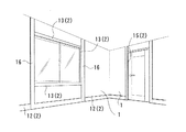
ここで、この実施例における化粧材の種類について説明する。図1及び図2は、住宅の室内において壁1の内壁面(壁の開口部の内側面、天井の段差の垂直面、床の段差の垂直面を含む)に取り付けられた各種化粧材2を示すものである。化粧材2としては、壁1の内壁面の天井との境界部分に設けられる廻り縁11、壁1の内壁面の床との境界部分に設けられる巾木12や、壁1に形成された窓となる開口部のサッシ枠より屋内側に設けられた窓枠13や、壁1の開口部に設けられた見切り枠14や、壁の内部ドアとなる開口部に設けられたドア枠15などがある。また、窓枠13、ドア枠15等においては、さらに化粧材2として、窓枠13やドア枠15の外側に、窓枠13やドア枠15につながった状態でケーシング16が設けられる場合もある。
【0022】
そして、図3及び図4に示されるのは、上記各種化粧材2の一例としての廻り縁11である。この一例において、廻り縁11は、壁1等に取り付けられる受材17と、該受材17に取り付けられる化粧面部材21と、該化粧面部材21に設けられ、受材17と嵌合する一対の挟持片22a、22bと、化粧面部材21に接合される分割部31(図4に図示)とを備えている。
そして、上記受材17は、例えば、断面矩形状の木材からなるものであるが、木材に限られるものではなく、樹脂であっても良い。なお、受材17を樹脂とする場合には、断面矩形状とする必要はなく、例えば、断面コ字状や、内部に中空を有する四角筒状などとしても良い。また、受材17を樹脂製の断面コ字状とする場合には、開口する側が内壁面側ではなく、内壁面の反対側を向いた状態となることが好ましい。
【0023】
上記化粧面部材21は、化粧材2としての廻り縁11において、主に露出する化粧面を有するものであり、化粧面部材21の表側が化粧面となっている。そして、化粧面部材21は、図1に示されるように左右に延在する長尺なものである。また、化粧面部材21の下部には、分割部31と嵌合する嵌合部23が設けられている。すなわち、化粧面部材21は、化粧材2(廻り縁11)の本体となるものであり、分割部31は、化粧材2の上下の側縁部のうちの下側の側縁部となるものである。
【0024】
上記嵌合部23は、ほぼ逆U字状に形成され、化粧面部材21の下端面に溝24が設けられた状態となっている。そして、溝24には、分割部31の後述する長片32もしくは短片33のいずれか一方が挿入された状態に嵌合するようになっている。そして、溝24は、奥側の幅が狭く、開口側の幅が広くなっている。また、溝24の幅は、奥側に向かうにつれて段階的に狭くなるようにされている。そして、溝24は、図4に示すように、基本的に奥側の幅の狭い挟幅部24aと、開口側の幅の広い拡幅部24bとを有するものとなっている。また、溝24においては、二つの内側面のうちの内壁面に近い側の内側面に段差24cが形成されることで、挟幅部24aと、拡幅部24bの幅が段階的に変えられている。また、溝24には、分割部31の長片32もしくは短片33が挿入されて嵌合されることになるが、その際の長片32もしくは短片33の挿入方向に沿った溝24の拡幅部24bの長さ(溝24の開口から挟幅部24aまでの長さ)が、分割部31の長片32及び短片33の後述する薄部32a、33aの長さ(長片32もしくは短片33の先端部から厚部32b、33bの先端までの長さ)より短くなっている。さらに、溝24の挟幅部24aの上記挿入方向に沿った長さが、上記長片32及び短片33の薄部32a、33aの長さより長くなっている。
【0025】
また、溝24の互いに対向し、かつ、分割部31の長片32もしくは短片33に当接する内側面(ここでは挟幅部24aの内側面)には、それぞれ、断面がほぼ鋸歯状の抜け止め部25、25が形成されているとともに、互いに対向する抜け止め部25、25同士の間隔が分割部31の長片32及び短片33(薄部32a、33a)の厚みより僅かに狭くなっており、溝24に分割部31の長片32及び短片33を押込んだ際に嵌合部23が弾性変形して、長片32もしくは短片33が溝に挿入可能となるとともに、嵌合部23の弾性力により嵌合部23に分割部31が押えられて嵌合するようになっている。また、嵌合部23と分割部31とは接着剤により接着されている。
【0026】
上側の上記挟持片22aは、化粧面部材21の上端部から後方に延出して形成され、下側の挟持片22bは、化粧面部材21の下部で、かつ、上記嵌合部23の上部から後方に延出している。そして、上側の挟持片22aと下側の挟持片22bとは、互いに対向しており、上側の挟持片22aと下側の挟持片22bとの互いに対向し、かつ、受材17に当接する面には、断面ほぼ鋸歯状の抜け止め部26、26が形成されている。なお、受材17を上述のように樹脂製とした場合には、受材17の挟持片22a、22bと当接する面にも断面ほぼ鋸歯状の抜け止め部を形成して、さらに引抜抵抗力を高めるものとしても良い。また、一対の挟持片22a、22bの互いに対向する面の化粧面部材21の裏面との接合部分には、挟持片22a、22bと受材17とを接着剤で接合する際に、余分な接着剤を溜める空間となる凹部27、28が形成されている。
【0027】
該凹部27、28は、挟持片22a、22bと化粧面部材21の裏面との境界に沿って溝状とされている。そして、上側の挟持片22aの抜け止め部26と下側の挟持片22bとの間の間隔は、受材17の上下長さより僅かに短いものとされ、上下の挟持片22a、22bの間に、受材17を押込んだ際に上下の挟持片22a、22bが弾性変形して受材17を挟持片22a、22b同士の間に挟み込むことが可能となるとともに、挟持片22a、22bの弾性力により受材17を挟んで嵌合できるようになっている。
【0028】
上記分割部31は、図4に示すように、長片32と短片33とが直角に接合されてL字状に形成され、後述する内装材と廻り縁11との見切り材として機能する部分である。そして、長片32と短片33とは、その先端部が溝24の挟幅部24aに対応する厚みを有する薄部32a、33とされ、該薄部32a、33aより後ろ側が溝24の拡幅部24bに対応する厚みを有する厚部32b、33bとされている。従って、長片32及び短片33は、先端に向かうにつれて薄くなる形状とされている。また、長片32及び短片33は、段差32c、33cの部分で段階的に厚みが変えられており、先端に向かうにつれて段階的に細くなるようになっている。そして、長片32及び短片33の薄部32a、33aの上記挿入方向に沿った長さが溝24の拡幅部24bより長くされ、かつ、挟幅部24aより短くされている。
【0029】
そして、分割部31は、化粧面部材21の嵌合部23にその長片32と短片33とのうちの一方を嵌合するようになっている。そして、長片32を嵌合部23に嵌合させた場合には、短片33が化粧面部材21の嵌合部23から内壁面に向かって延出した状態となり、短片33を嵌合部23に嵌合させた場合には、長片32が化粧面部材21の嵌合部23から内壁面に向かって延出した状態となるようになっている。そして、短片33を内壁面に向かって延出させた場合には、短片33と内壁面との間の間隔が広くなり、長片32を内壁面に向かって延出させた場合には、長片32と内壁面との間の間隔が狭くなるようになっている。なお、長片32及び短片33は、化粧面部材21の嵌合部23の溝24に嵌合する突条とみなすことができる。
【0030】
これは、内壁面に貼られる内装材(図示略)としてクロス(壁紙)等の薄いシート状の部材と、少し厚い板状(ボード状)の部材とのいずれか一方が用いられることを想定したものである。なお、内装材は、下の挟持片22bの位置の下から内壁面に貼られるようになっており、内装材の上端部が廻り縁11の分割部31の裏側に隠れるようになっている。そして、厚いボード状の内装材を用いる場合には、分割部31の短片33が内壁面に向かうようにして、内装材が貼られる前の内壁面と短片33の先端との間に厚いボード状の内装材が挟まれるようにし、薄いシート状の内装材を用いる場合には、分割部31の長片32が内壁面に向かうようにして、内装材が貼られた内壁面と長片32との間にほとんど間隔があかないようにしている。すなわち、この一例の廻り縁11は、一種類で厚みの異なる複数種類の内装材に対応できるようになっている。なお、図5に示される廻り縁11a(受材17及び分割部31を図示省略)は、上記廻り縁11と同様の形状を有するものであるが、その上下高さが廻り縁11より長くなっている。そして、上記廻り縁11aにおいては、その上下長さが長くなっていても、同じ分割部31を用いることができるようになっており、廻り縁11、11aの種類を増やした場合に部品点数が多くなるのを抑制できるようになっている。
【0031】
そして、廻り縁11を備えた内装構造においては、内壁面に上記受材17が釘やビス等の接合部材により接合されて取り付けられている(接着剤を用いるものとしても良い)。また、内壁面の受材17より下側には、内装材が貼設されている。そして、上記受材17には、二つの挟持片22a、22bに受材17を挟み込むようにして挟持片22a、22bが受材17に嵌合することにより化粧面部材21が受材17に接合されている。なお、嵌合部23を含む化粧面部材21と、挟持片22a、22bとは、上述の木質様成形品であり、例えば、押出成形により一体に成形されており、樹脂として弾性を備えたものとなっている。また、分割部31も木質様成形品である。そして、受材17と挟持片22a、22bとは、上述のように嵌合するとともに接着剤により接着されている。また、化粧面部材21は、上述のように内装材に厚みに対応して分割部31が取り付けられている。また、分割部31は、その長片32もしくは短片33が溝24に嵌合するとともに、接着剤により長片32もしくは短片33と溝24の内側面とが接着させられている。
【0032】
次に、廻り縁11の施工方法及び作用効果を説明する。まず、内壁面に受材17を固定する。一方、化粧面部材21に分割部31を嵌合させる。この際には、予め、化粧面部材21の溝24の内側面に接着剤を塗布しておく。そして、上述のように溝24は、開口部側が広くされ、分割部31の長片32及び短片33の先端部が薄くされているので、溝24に長片32及び短片33を容易に挿入することができる。また、溝24は、一方の内側面側だけに段差24cが形成されることで、幅の広い開口部側の拡幅部24bと幅の狭い奥側の挟幅部24aとがわけられており、他方の内側面側には、段差がほとんど形成されていない状態なので(抜け止め部25の小さな段差は存在しているが、小さいので後述の作用においては無視することができる)、溝24に長片32もしくは短片33の先端部を挿入した後に、長片32もしくは短片33を溝24の段差がほとんどない他方の内側面に沿って(案内された状態で)、溝24の奥まで長片32もしくは短片33を挿入していけば、長片32もしくは短片33の先端部を溝24の挟幅部24aに円滑に挿入することができるとともに、長片32もしくは短片33の厚部32b、33bの先端部を溝24の開口に円滑に挿入させることができる。
【0033】
また、長片32及び短片33の先端側の薄部32a、33aの長さが、溝24の拡幅部24bの長さより長くされているので、溝24に長片32及び短片33を挿入していく際に、溝24の挟幅部24aに長片32もしくは短片33の先端部が挿入された状態となる前に、溝24の開口に長片32もしくは短片33の厚部32b、33bの先端が挿入されることがない。従って、長片32もしくは短片33の厚部32b、33bが溝24に挿入される際には、既に、長片32もしくは短片33の先端部が挟幅部24aに挿入されていることにより、挟幅部24aに長片32もしくは短片33の薄部32a、33aが案内された状態で、長片32もしくは短片33の厚部32b、33bが溝24の開口から挿入されることになり、さらに円滑に長片32もしくは短片33の厚部32b、33bを溝24に挿入することができる。
【0034】
また、化粧面部材21の溝24の内面に接着剤を塗布した状態で、溝24に長片32もしくは短片33を挿入した場合には、余分な接着剤が長片32もしくは短片33に押されて溝24の奥側に移動することになる。この際に、長片32及び短片33の先端側の薄部32a、33aの上記挿入方向に沿った長さが溝24の挟幅部24aの挿入方向に沿った長さより短いので、溝24に長片32もしくは短片33を押込んで行った際に、長片32もしくは短片33の先端が溝24の最も奥に至る前に、長片32もしくは短片33の段差32c、33cが溝24の段差24cに当たり、それ以上長片32もしくは短片33を奥に挿入できない状態となり、溝24の奥には、長片32もしくは短片33が挿入されていない空間が生じることになる。そして、この空間に上述のように溝24の奥側に押された接着剤が押込まれた状態となるので、余分な接着剤は上記空間に収容された状態となり、余分な接着剤が溝24からあふれ出すようなことがない。
【0035】
また、溝24の内側面と、長片32及び短片33の側面とは、それぞれ段階的に幅や厚みを変化させることから、溝24に長片32もしくは短片33を挿入する挿入方向とほぼ平行な面とすることができる。すなわち、溝24の内側面と、長片32及び短片33の側面とが幅や厚みを変更するために、上記挿入方向に対して斜めとなってくさび状の形状となる必要がなく、溝24の内側面と、長片32及び短片33の側面とをほぼ上記挿入方向に沿ったものとすることができる。これにより、溝24に長片32もしくは短片33を挟んだ状態とし、かつ、化粧面部材の弾性力により長片32もしくは短片33を挟んで押えるようにした場合に、溝24、長片32及び短片33がくさび状の形状になっていた場合のように、長片32や短片33を外に押出すような力が働くことがない。
【0036】
また、溝24の内側面には、断面ほぼ鋸歯状の抜け止め部が設けられており、溝24から長片32もしくは短片33が抜けるのを抑制することができる。これらのことから、溝24に長片32もしくは短片33を嵌合させた状態で接着させる際に、接着剤の接合力が十分に発現するまで溝24に長片32もしくは短片33を強固に嵌合させておくことができる。次いで、受材17に化粧面部材21と一体の挟持片22a、22bを嵌合させる。この際には、挟持片22a、22bの互いに対向し、かつ、受材に当接する面に予め接着剤を塗布しておく。そして、挟持片22a、22bの間に受材17が押込まれるように、化粧面部材21を受材17に向かって押し付ける。この際には、挟持片22a、22bの接着剤が塗布された面に受材17が押し付けられるとともに、受材が挟持片22a、22aの先端部から基端部側に移動していくことになる。そして、この場合に、挟持片22a、22bに余分に塗布された接着剤が受材17に押されて挟持片22a、22bの基端部側に寄せ集められて行く。そして、挟持片22a、22bの基端部、すなわち、化粧面部材21の裏面との境界部分には、上述の凹部27、28が形成されているので、該凹部27、28内に寄せ集められた接着剤が受材17により押し入れられることになる。これにより、余分な接着剤が受材と化粧面部材21の挟持片22a、22bとの嵌合部分の外側に露出するのを防止することができる。
【0037】
なお、溝24の幅と、長片32及び短片33の厚みとを変化させる際に段階的に変化させるものとしたが、連続的に幅や厚みを変化させるものとしても良い。しかし、この場合には、上述のように溝24に対して長片32や短片33が抜けやすい状態となる可能性がある。また、溝24の二つの内側面のうちの一方の内側面だけに段差24cを設けるものとし、長片32及び短片33においても、一方の側面だけに段差32c、33cを設けるものとしたが、溝24の両方の内側面と、長片32及び短片33の両方の側面に段差を設けるものとしても良い。しかし、この場合には、溝24の段差の無い内側面に、長片32もしくは短片33を案内させることができない。また、溝24の内側面だけではなく、長片32や短片33の側面にも断面ほぼ鋸歯状の抜け止め部を設けるものとしても良く、このようにすれば、さらに、溝24に対する長片32や短片33の引抜抵抗力を高めることができる。
【0038】
次に、廻り縁11以外の化粧材2として窓枠13を説明する。
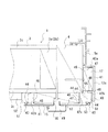
図6は、上記化粧材2のうちの窓枠13と、該窓枠13を備えた内装構造を示すためのものであり、壁1の窓となる開口部の左側の水平断面図である。なお、図6において、壁1は、壁パネル3からなるものであり、壁パネル3は、框材3aを矩形枠状に組むとともに枠内部に縦横に棧材(図示略)を配置した枠組3bと、該枠組3bの左右両面に貼設された面材3c、3cとからなるものである。なお、図6においては、壁パネル3の外面側に貼設される外装材を省略して図示している。また、壁1の開口部との境となる部分には方立て4が配置されている。図6において、方立て4より右側が窓となる開口部である。そして、図6に示されるように、壁1の開口部の内側面の外よりの部分には、サッシ枠5が取り付けられ、内よりの部分には窓枠13が取り付けられている。なお、図6においては、壁1の内面側の窓に隣接する部分にケーシング16が取り付けられない構造となっている。
【0039】
そして、窓枠13は、基本的に廻り縁11と同様に、受材17と、化粧面部材41(本体部)と、該化粧面部材41に設けられ、受材17と嵌合する一対の挟持片42a、42bと、化粧面部材41に接合される分割部51(側縁部)とを備えているものである。なお、これら受材17、化粧面部材41、挟持片42a、42b、分割部51は、上記廻り縁11の同名の部材と細部の構造やサイズ等が異なるものの基本的に同様の構成を有し、かつ、同様の材質からなるものである。
【0040】
上記受材17は、上記廻り縁11の受材17とサイズ以外は同様のものである。上記化粧面部材41は、その表側が化粧面となっており、上下に延在する長尺なものである。また、化粧面部材41の壁の内側に向かう端部には、上記分割部51と嵌合する嵌合部43が設けられている。該嵌合部43においては、化粧面部材41の他の部分より厚く形成されるとともに、裏面側に嵌合溝44が形成され、該嵌合溝44に、分割部51が嵌合している。
【0041】
そして、嵌合溝44は、基本的に廻り縁11の化粧面部材21の溝24と同様の形状を有するものである。すなわち、嵌合溝44は、奥側の幅が狭く、開口側の幅が広くなっている。また、嵌合溝44の幅は、奥側に向かうにつれて段階的に狭くなるようにされている。そして、嵌合溝44は、基本的に奥側の幅の狭い挟幅部44aと、開口側の幅の広い拡幅部44bとを有するものとなっている。また、嵌合溝44においては、二つの内側面のうちの内壁面に近い側の内側面に段差44cが形成されることで、挟幅部44aと、拡幅部44bの幅が段階的に変えられている。また、嵌合溝44には、分割部51の後述する突条53が挿入されて嵌合されることになるが、その際の突条53の挿入方向に沿った嵌合溝44の拡幅部44bの長さが、分割部51の突条53の後述する薄部53aの長さより短くなっている。さらに、嵌合溝44の挟幅部44aの上記挿入方向に沿った長さが、分割部51の突条53のの薄部53aの長さより長くなっている。
【0042】
また、嵌合溝44の互いに対向し、かつ、分割部51の突条53に当接する内側面(ここでは挟幅部44aと拡幅部44bとの内側面)には、それぞれ、断面がほぼ鋸歯状の抜け止め部(図示略)が形成されている。また、嵌合部43と分割部51とは接着剤により接着されている。上記挟持片42a、42bは、化粧面部材41の裏面の外より側の部分と、内より側の部分とからそれぞれ後方に延出している。また、挟持片42a、42bの互いに対向する面には、廻り縁11の挟持片22a、22bの抜け止め部26、26及び凹部27、28と同様の構成を有する抜け止め部46、46及び凹部47、48が廻り縁11の場合と同様の位置に設けられている。
【0043】
上記分割部51は、廻り縁11の分割部31が内装材の上端部を覆い隠すようになっていたのに対して、内装材の下地となる石膏ボード52及び巾木12の開口部側の端部に当接して、化粧面部材41の裏面や受材17を隠すようになっている。そして、上記分割部51は、上記化粧面部材41の嵌合部43の嵌合溝44に嵌合する突条53と、突条53を嵌合部43に嵌合させた状態で化粧面部材41の後方側に延出する本体部54と、本体部54の突条53の反対側に形成され、石膏ボード52及び巾木12に当接する当接面55とを有するものである。
【0044】
上記突条53は、(図6の分割部51に代えて、図11の右側に図示された分割部51を参照して説明する。なお、図6の分割部51の突条53と図11の分割部51の突条53は同じ形状を有するものである)その先端部が嵌合溝44の挟幅部44aに対応する厚みを有する薄部53aとされ、該薄部53aより後ろ側が嵌合溝44の拡幅部44bに対応する厚みを有する厚部53bとされている。従って、突条53は、先端に向かうにつれて薄くなる形状とされている。また、突条53は、段差53cの部分で段階的に厚みが変えられており、先端に向かうにつれて段階的に細くなるようになっている。そして、突条53の薄部53aの上記挿入方向に沿った長さが嵌合溝44の拡幅部44bより長くされ、かつ、挟幅部44aより短くされている。また、突条53の薄部53a及び厚部53bの側面には、それぞれ断面ほぼ鋸歯状の抜け止め部(図示略)が設けられている。
【0045】
また、分割部51の本体部54の屋内側に臨む面は、屋内側に突出した状態となって意匠性を高めるようになっている。また、分割部51が、化粧面部材41に対して分割可能となっているのは、後述するように角部で窓枠13、見切り枠14、ドア枠15等の化粧材2(化粧枠)が互いに隣接する場合に、これらの分割部51となる部分同士が互いにぶつかってしまい分割部51の部分が邪魔になって化粧材2が取り付けられない状態となるの防止するために、隣接する化粧材2のうちの一方の化粧材2の分割部51を外した状態として、これら化粧材2を隣接して配置できるようにしたものである。そして、上記窓枠13においても、分割部31と分割部51との一部の機能の違い以外は、廻り縁11と同様の作用効果を得ることができる。
【0046】
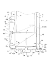
図7に示される内装構造は、図8及び図9に示すように、第一の壁1aに第二の壁1bが直角に接合され、第一の壁1aの第二の壁1bが接合される部分に隣接して窓となる開口部1cが設けられ、第二の壁1bの第一の壁1aと接合する部分にドア(図示略)がはめ込まれる開口部1dが設けられた場合のように、壁1同士が直角に接合された部分の角部で該角部を挟んで窓枠13aとドア枠15とが隣接して配置された場合のものである。そして、図7は、第一の壁1aの第二の壁1bと接合される部分の水平断面図である。なお、第一の壁1aも図6で示した壁1と同様の壁パネル3からなり開口部側の端部に方立て4が接合されている。
【0047】
上記窓枠13aは、上記窓枠13と同様に、受材17と、化粧面部材41と、該化粧面部材41に設けられ、受材17と嵌合する一対の挟持片42a、42bと、化粧面部材41に接合される分割部51とを備えてなるものである。そして、窓枠13aにおいては、化粧面部材41の外より側の端部が外より側の挟持片42aの位置までとされている以外は、窓枠13と同様の構成となっている。そして、化粧面部材41の嵌合部43には、窓枠13の場合と同様に同様の形状を有する嵌合溝44が設けられている。一方、窓枠13aの分割部51も窓枠13の分割部51と全く同様の形状を有するものである。そして、窓枠13aは、ともに用いられるサッシ枠5の形状に対応して、窓枠13と異なる断面形状とされたものであり、対応するサッシ枠5の形状が異なるだけで窓枠13と同様に用いることができるものである。なお、窓枠13aにおいては、上述のように角部でドア枠15と隣接する場合に、予め分割部51が取外された形状となっている。このようにすることで、ドア枠15の分割部51と窓枠13aの分割部51がほぼ同じ位置に配置されることにより、ドア枠15もしくは窓枠13aが配置できなくなるのを防止することができる。言い換えれば、ドア枠15及び窓枠13aにおいて、特に角部専用のドア枠15や窓枠13aを予め用意しなくとも、単独で用いられるドア枠15もしくは窓枠13aに分割部51を取り付けない状態(外した状態)とすれば、ドア枠15や窓枠13aが角部で互いに隣接している場合にも用いることができる。
【0048】
従って、設置する部分の状況に対応してドア枠15や窓枠13aに、形状の異なる規格のものを製造したり、その場で形状を変えるように加工したりする必要がなく、部品種類の低減、施工の省力化等を図り、最終的にコストダウンを図ることができる。また、角部において窓枠13,13aやドア枠15に分割部51が用いられない場合には、化粧面部材41に分割部51を取り付けずにそのまま用いることができ、かつ、単独で窓枠13,13aやドア枠15を用いる場合等おいては、上述のように化粧面部材41に分割部51を取り付けることになるが、この場合には、廻り縁11において化粧面部材21に分割部31を付けた場合と同様に極めて容易に化粧面部材21に分割部51を取り付けることができ、かつ、化粧面部材21に分割部51が強固に接着されるまで、化粧面部材21に分割部51を強固に嵌合させた状態とすることができる。
【0049】
また、ドア枠15及び窓枠13aが角部で隣接した場合に、それぞれの化粧面部材41、41の角部の頂点側の端部が当接せずに互いに間隔をあけた状態となるようになっている。そして、この間隔の部分には、ドア枠15もしくは窓枠13aの一方に取り付けられた分割部51が配置されて、上記間隔が分割部51により閉塞された状態とされる。また、この際に、分割部51の角部が上記間隔から外部に露出した状態となり、分割部51の角部と二つの化粧面部材41、41の端部から几帳面状の形状が形成され、意匠性を高めるようになっている。
【0050】
上記ドア枠15は、基本的に窓枠13と同様の構成を有するものであり、受材17a(受材17に戸当たり49を取り付けるための溝を設けたもの)と、化粧面部材41と、該化粧面部材41に設けられ、受材17aと嵌合する一対の挟持片42a、42bと、化粧面部材41に接合される分割部51とを備えるものである。なお、ドア枠15においては、基本的に左右対称の形状とされ、化粧面部材41の左右端部にそれぞれ嵌合部43が設けられ、該嵌合部43にそれぞれ分割部51が嵌合するようになっている。また、化粧面部材41の中央部に戸当たり49が取り付けられるスリット50が設けられている。また、ドア枠15の挟持片42a、42bの互いに対向する面には、窓枠13の場合と同様に、抜け止め部46、46及び凹部47、48が設けられている。
【0051】
そして、ドア枠15において、化粧面部材41の嵌合部43に形成された嵌合溝44は、上述の窓枠13における嵌合溝44と同じ形状を有するものであり、分割部51も窓枠13の分割部51と同じ形状を有するものである。このようなドア枠15及び窓枠13aにおいても、上記廻り縁11や窓枠13と同様に、容易に化粧面部材41に分割部51を接合することができ、かつ、化粧面部材41に分割部51が強固に接着されるまで、化粧面部材41に分割部51を強固に嵌合しておくことができる。また、ドア枠15においては、図7に示すように、壁1を構成する壁パネル3の開口部側の端面ではなく、壁パネル3の側面に取り付けられる場合もあり、この場合には、上述の分割部51の当接面ではなく、本体部54の屋内側に臨む面が石膏ボード52等に当接することになる。
【0052】
図10及び図11は、上述のような角部に窓枠13a、13a同士が互いに隣接して配置された場合と、角部にドア枠15、15同士が互いに隣接して配置された場合とを示すものであり、上述の角部にドア枠15と窓枠13aとを隣接して配置した場合と異なるバリエーションを示すものである。この場合も互いに隣接する窓枠13a、13a同士もしくはドア枠15、15同士において、一方の窓枠13aもしくはドア枠15に分割部51が取り付けられ、他方の窓枠13aもしくはドア枠15(角側)に分割部51が取り付けられていない状態となっている。これにより、窓枠13aやドア枠15が上述のように角部で一部が互いに重なって配置されるような場合でも、単独で用いられる窓枠13aやドア枠15を分割部51を取り付けない状態とするだけで使用できる。また、分割部51により、上述の場合と同様に窓枠13a同士もしくはドア枠15同士で形成される角部を几帳面状の形状とすることができる。また、図10及び図11に示される内装構造において、図7の場合と同様の形状を有する窓枠13a及びドア枠15が用いられており、図7の場合の窓枠13a及びドア枠15と同様の作用効果を奏することができる。なお、図10においては、受材17が壁パネル3ではなく、柱状の木材60に取り付けられる。なお、木材60は、壁の角部の二つの窓に挟まれた部分を構成するものである。
【0053】
【発明の効果】
本発明の請求項1記載の住宅の化粧材によれば、化粧材が本体部と一方の側縁部とに二分割された状態となっており、これらを接合する場合と接合しない場合や、接合の仕方を変えた場合などによって、状況に応じて化粧材を変形することができる。そして、側縁部と上記本体部とのいずれか一方に長さ方向に沿った溝が形成されるともに、他方に該溝に嵌合する突条が形成され、上記溝に上記突条を嵌合させることで、本体部と側縁部とが接合され、かつ、上記溝の内側面に段差が形成されることで上記溝の幅が段階的に変化することにより該溝の奥の幅より開口部側の幅が広くされ、かつ、上記突条が上記溝に対応して、その厚みが段階的に変化することにより、先端部が後部より薄くされているので、溝の開口部が突条の先端部に対して広いものとなり、容易に溝の開口部に突条を挿入できるとともに、溝の内面に案内された状態で溝に突条を嵌合させることができる。
また、溝に対する突条の引抜抵抗力を抜け止め部により高めることができる。
【0054】
また、溝の幅及び突条の太さが段階的に変化するので、溝の内面と突条の外面とを溝に対する突条の引抜方向とほぼ平行にすることが可能であり、溝の内面や突条の外面が例えばくさび状となることにより、溝に対して突条が抜けやすい状態となるのを防止することができる。本発明の請求項記載の住宅の化粧材によれば、溝に突条をスムーズに嵌合させることができる。
【0055】
本発明の請求項記載の住宅の化粧材によれば、接着剤多少余分に塗布されていても、余分な接着剤が溝と突条との嵌合部から漏出するのを防止することができる。
【図面の簡単な説明】
【図1】本発明の実施の形態の一例の化粧材が用いられる部分を示す住宅内部の要部斜視図である。
【図2】上記例の化粧材が用いられる部分を示す住宅内部の要部斜視図である。
【図3】上記例の化粧材のうちの廻り縁の一部を示す側面図である。
【図4】上記例の化粧材のうちの廻り縁の一部を示す側面図である。
【図5】上記廻り縁と形状が異なる廻り縁の化粧面部材を示す側面図である。
【図6】上記例の化粧材のうちの窓枠の一例を示す断面図である。
【図7】上記例の化粧材のうちの窓枠とドア枠が壁同士が直角に接合された角部において隣接して配置された状態を示す断面図である。
【図8】上記例の窓枠とドア枠が隣接して配置される部分を説明するための図面である。
【図9】上記例の窓枠とドア枠が隣接して配置される部分を説明するための住宅内部の要部斜視図である。
【図10】上記例の化粧材のうちの窓枠同士が角部において隣接して配置された状態を示す断面図である。
【図11】上記例の化粧材のうちのドア枠同士が角部において隣接して配置された状態を示す断面図である。
【符号の説明】
1 壁
2 化粧材
11 廻り縁(化粧材)
12 巾木(化粧材)
13 窓枠(化粧材)
14 見切り材(化粧材)
15 ドア枠(化粧材)
16 ケーシング(化粧材)
21 化粧面部材
23 嵌合部
24 溝
24a 挟幅部
24b 拡幅部
31 分割部
32 長片(突条)
33 短片(突条)
32a 薄部
32b 厚部
33a 薄部
33b 厚部
41 化粧面部材
44 嵌合溝(溝)
44a 挟幅部
44b 拡幅部
51 分割部
53 突条
53a 薄部
53b 厚部
[0001]
BACKGROUND OF THE INVENTION
The present invention relates to a decorative material for a house that is attached to an inner wall surface such as an edge of a wall of a house or an edge around a wall opening.
[0002]
[Background technology]
In general, in the interior of a house, for example, the surrounding edge provided on the boundary portion of the inner wall surface of the wall (the upper edge of the inner wall surface) or the boundary portion of the inner wall surface of the wall (the inner wall surface) A decorative material such as a decorative frame provided on a baseboard provided on the lower edge) or an edge of the opening of the inner wall surface is attached.
[0003]
Generally, wood is used as the decorative material, but a resin may be used. Moreover, it replaces with wood and uses the wood-like molded article in "the cellulosic fine particle, the wood-like molded article, and the wood-like product" described in PCT JP94 / 00351 (International publication number: WO94 / 20280) as a cosmetic material. Some things have been done. Here, the said wood-like molded product is demonstrated easily. A pulverized powder obtained by pulverizing a cellulose material (basically wood) as a raw material is ground to obtain a granule having an increased bulk specific gravity, and the outer peripheral surface of the granule has a smaller diameter than the granule and Hard surface particles (basically titanium oxide particles) are fixed to form fixed particles, and resin and pigment are mixed and melted in the fixed particles, and then formed into a desired shape by extrusion or injection molding simultaneously with melting. It is molded.
[0004]
The wood-like molded product has a pattern that is very close to the grain of natural wood, and the texture such as the feeling of touch is close to that of natural wood. In addition, this wood-like molded product can be used by regenerating wood scraps and waste materials, and can effectively use the scrap materials and waste materials, and has excellent moldability compared to wood. It has a homogeneous material. Therefore, by using a wood-like molded product for the decorative material, it is possible to obtain the same texture as wood and improve the quality and stabilize the quality while considering the environment.
[0005]
For example, when a decorative material made of a wood-like molded article or other resin as described above is attached adjacently at the corner of the core, a method for forming a grid-like shape at the corner is disclosed in JP-A-10-331387. A decorative frame described in Japanese Patent Publication No. Gazette has been proposed.
In the above publication, for example, a decorative frame base material (receiving material) is attached to the surface sandwiching the corner portion of the core material, and a decorative surface member is attached to the receiving material so that the corner member of the core material is sandwiched between the surfaces. Each forms a decorative face. Further, by arranging the decorative frame corner member so that the corner is exposed between the decorative face members arranged with the corner portion interposed therebetween, the decorative face member is exposed from between the end portions and the end portions, respectively. From the corner of the decorative frame corner member, the shape of a checkered surface (a state in which the corner has a plurality of steps, protrusions, etc.) is formed at the corner of the core.
[0006]
[Problems to be solved by the invention]
By the way, when a decorative frame (window frame, door frame, etc.) is formed on the inner wall of the inner wall of, for example, an entrance / exit or an opening serving as a window, the side edge toward the indoor side of the decorative frame is fundamental. It protrudes from the inner wall surface. In addition, when there is a decorative material such as a baseboard on the inner wall surface, the side edge portion of the decorative frame that faces the indoor side projects from the decorative material such as the baseboard to the indoor side. In addition, even if there is no baseboard, for example, gypsum board or interior material is affixed to the inner wall surface, and when the plasterboard or interior material is removed from the inner wall surface, the interior side of the decorative frame The side edge part which goes to has become the state which protruded toward the indoor side considerably.
[0007]
As described in the background art, if such two decorative frames are arranged adjacent to each other with the corner portion of the core or the like sandwiched therebetween, the two decorative frames adjacent to each other at the corner portions protrude toward the indoor side. The parts are arranged at positions where they overlap each other. Therefore, the decorative frame used alone cannot be arranged adjacent to each other with the corner portion interposed therebetween. Therefore, when the decorative frame is arranged adjacent to the corner, the decorative frame that is used alone is processed, or, for example, a notebook surface is configured with the corner as in the above publication. It was necessary to use a decorative frame for the corner.
[0008]
On the other hand, the surrounding edge as a decorative material serves as a parting material for the ceiling surface and the inner wall surface, and for example, is a parting material for interior materials to be affixed to the inner wall surface, and is attached to the inner wall surface by the surrounding edge. The upper end of the interior material is covered and hidden. However, there are two types of interior materials, so-called wallpaper and other thin sheet-like materials, and thick board-like materials. When thin sheet-like interior materials are used, the surrounding edges are thick board-like interiors. It could not be used when the material was used.
From the above, depending on the usage condition of the cosmetic material, there is a problem that the same type of cosmetic material requires different standards, and the types of the cosmetic material increase.
[0009]
And as a method of reducing the kind of decorative material, for example, if a part of the decorative material is divided into, for example, a structure that can be cut off, for example, a part that protrudes to the indoor side of the decorative frame, it can be used alone. When using it, use it as it is, and when using it adjacent to the corner, cut off the part protruding to the indoor side and use it alone with a single standard decorative frame It is possible to use both when two corners are adjacent to each other. However, in this case, there is a problem in workability and the like when a part of the cosmetic material is cut because the strength is secured and the structure can be cut.
[0010]
The present invention has been made in view of the above circumstances, and an object of the present invention is to provide a cosmetic material that can be used in different situations as a deformable cosmetic material of the same standard and can improve workability. And
[0011]
[Means for Solving the Problems]
  The housing decorative material according to claim 1 of the present invention is, for example, a housing attached to an inner wall surface such as an edge of a wall of a house or an edge around a wall opening as shown in FIGS. The at least one side edge (divided portion 31) and the main body portion (decorative face member 21) excluding the side edge portion 31 are divided, and the side edge portion 31 and the main body portion 21 are separated. And a groove (long piece 32 or short piece 33) that fits into the groove 24 is formed on the other side, and the protrusion 24 is formed in the groove 24. By fitting 32, the main body 21 and the side edge 31 are joined,By forming a step 24c on the inner surface of the groove 24, the width of the groove 24 is changed stepwise, so that the width on the opening side is made wider than the width behind the groove 24, and the protrusion 32 corresponds to the groove 24, and the thickness thereof changes stepwise so that the tip is thinner than the rear,
  Both the outer surface of the ridge 32 and the inner surface of the groove 24 are formed with a substantially serrated cross-section retaining portion,
  The sawtooth of the retaining portion 25 formed on the inner surface of the groove 24 is larger than the sawtooth of the retaining portion formed on the outer surface of the protrusion 32.
[0012]
  According to the above configuration, the cosmetic material 2 is divided into the main body 21 and the one side edge 31 so that only the main body 21 can be used or the main body 21 and the side can be used depending on the situation. It becomes possible to join and use the edge 31. Further, by allowing a plurality of types of side edge portions 31 to correspond to a kind of main body portion 21, or conversely, a plurality of types of body edge portions 21 corresponding to a kind of side edge portion 31, When many types of cosmetics 2 are used, only the common part has the same shape, and cost can be reduced. Further, by changing the way of joining the main body portion 21 and the side edge portion 31, it is possible to change the shape and cope with different situations. A groove 24 along the length direction is formed in one of the side edge portion 31 and the main body portion 21, and a protrusion 32 that fits into the groove 24 is formed in the other side. The main body 21 and the side edge 31 are joined by fitting the protrusion 32 to theBy forming a step 24c on the inner surface of the groove 24, the width of the groove 24 is changed stepwise, so that the width on the opening side is made wider than the width behind the groove 24, and the protrusion 32 corresponds to the groove 24, and the thickness thereof changes stepwise so that the tip is thinner than the rear.Therefore, the opening of the groove 24 is wider than the tip of the protrusion 32, and the protrusion 32 can be easily inserted into the opening of the groove 24, and the groove 24 is guided to the inner surface of the groove 24. 24 can be fitted with the ridge 32. Therefore, workability can be improved as compared with the conventional case of dividing a decorative material that can be divided in a state where strength is ensured.
  Further, the pulling-out resistance of the protrusion 32 with respect to the groove 24 can be increased by the retaining portion 25. Further, when an adhesive is used, the bonding by the adhesive can be ensured by firmly fitting the protrusions 32 into the groove 24 until the bonding force of the adhesive is developed.
[0014]
  AlsoSince the width of the groove 24 and the thickness of the protrusion 32 change stepwise, it is possible to make the inner surface of the groove 24 and the outer surface of the protrusion 32 substantially parallel to the drawing direction of the protrusion 32 with respect to the groove 24. By making the inner surface of the groove 24 and the outer surface of the protrusion 32, for example, wedge-shaped, it is possible to prevent the protrusion 32 from being easily removed from the groove 24.
[0015]
  Claims of the invention2The housing decorative material 2 described in the claim1In the decorative material 2 described above, the groove 24 has at least two-stage widths of at least a first narrow width portion 24a having a narrow width on the back side and a widened portion 24b having a wider width on the opening side than the narrow width portion 24a. The protrusions 32 correspond to the grooves 24, and the at least two of the first thin portion 32a having a thin thickness on the front side and the thick portion 32b having a thick thickness behind the thin portion 32a. The length of the first thin portion 32a of the first protrusion 32 along the insertion direction when the protrusion 32 is inserted into the groove 24 is the first step of the groove 24. It is characterized by being longer than the length along the insertion direction from the rear end of the narrow width portion 24a to the opening.
[0016]
According to the said structure, when fitting the protrusion 32 to the groove | channel 24, the opening of the groove | channel 24 becomes wider than the front-end | tip part of the protrusion 32 like the structure of Claim 1, and the protrusion 32 is in the groove | channel 24. When the ridge 32 is fitted into the groove 24, the tip of the ridge 32 (the thin portion 32a of the ridge 32 is formed at the rear end of the narrow width portion 24a on the back side of the groove 24. At the stage where the tip end is reached, the tip end of the thick portion 32b behind the thin portion 32a of the protrusion 32 has not yet reached the opening of the groove 24. Then, when the leading end of the thin portion 32 a of the protrusion 32 is inserted into the narrow width portion 24 a of the groove 24, the leading end of the thick portion 32 b of the protrusion 32 enters the groove 24 from the opening of the groove 24. . At this time, since the leading end portion of the thin portion 32a of the ridge 32 has already been guided by being inserted into the narrow width portion 24a of the groove 24, the position of the opening of the groove 24 and the ridge 32 are provided. The position of the tip of the thick part 32b is in a substantially corresponding state. Therefore, in this case, the position of the opening of the groove 24 and the tip of the thick part 32 b of the protrusion 32 are shifted, and the thick part 32 b of the protrusion 32 is caught in the opening of the groove 24. It can prevent that 32 will be in the state which cannot be fitted smoothly. That is, the protrusion 32 can be smoothly fitted into the groove 24.
[0017]
  Claims of the invention3The housing decorative material 2 described in the claim1 or 2In the decorative material 2 described above, the length of the first step narrow width portion 24a of the groove 24 along the insertion direction when the protrusion 32 is inserted into the groove 24 is the first thin width of the protrusion 32. The length of the part 32a is longer than the length along the insertion direction.
[0018]
According to the above configuration, the length of the first narrow width portion 24a of the groove 24 along the insertion direction when the protrusion 32 is inserted into the groove 24 is the first thin portion of the protrusion 32. Since the length of the ridge 32 is longer than the length along the insertion direction, when the ridge 32 is fitted into the groove 24, the narrow portion before the tip of the ridge 32 reaches the innermost portion of the narrow portion 24 a of the groove 24. The leading end portion of the thick portion 32 b of the ridge 32 hits the inlet portion of the ridge 32, and the leading end portion of the ridge 32 cannot be inserted to the innermost part of the groove 24. Accordingly, a space can be formed in the back of the groove 24 in a state where the protrusion 32 is fitted in the groove 24. At this time, the protrusion 32 is fitted into the groove 24, and the body portion 21 and the side edge portion 31 of the decorative material 2 are bonded with an adhesive at the fitting portion between the groove 24 and the protrusion 32. Then, when the protrusion 32 is inserted into the groove 24 and fitted, excess adhesive is pushed to the back side of the groove 24, and the deepest part of the groove 24 remaining when the protrusion 32 is fitted into the groove 24. Extra adhesive will be accommodated in the space. Therefore, even if the adhesive is applied to some extent, it is possible to prevent the excess adhesive from leaking out from the fitting portion between the groove 24 and the protrusion 32. In addition, the main body 21 and the side edge 31 are bonded to each other with the adhesive by bonding the main body 21 and the side edge 31 of the decorative material 2 with the protrusion 32 fitted in the groove 24. It is not necessary to temporarily fix the bonding force until it is expressed, and workability can be improved.
[0021]
DETAILED DESCRIPTION OF THE INVENTION
Below, the decorative material of the house of an example of embodiment of this invention is demonstrated with reference to drawings.
Here, the type of the decorative material in this embodiment will be described. 1 and 2 show various decorative materials 2 attached to the inner wall surface of a wall 1 (including the inner surface of the opening of the wall, the vertical surface of the ceiling step, and the vertical surface of the floor step) in the interior of the house. It is shown. The decorative material 2 includes a peripheral edge 11 provided at a boundary portion between the inner wall surface of the wall 1 and a baseboard 12 provided at a boundary portion between the inner wall surface of the wall 1 and a window formed on the wall 1. A window frame 13 provided on the indoor side from the sash frame of the opening, a parting frame 14 provided in the opening of the wall 1, a door frame 15 provided in the opening serving as an internal door of the wall, and the like. is there. Further, in the window frame 13, the door frame 15, etc., a casing 16 may be provided as a decorative material 2 in a state of being connected to the window frame 13 or the door frame 15 outside the window frame 13 or the door frame 15. .
[0022]
3 and 4 show a peripheral edge 11 as an example of the various decorative materials 2 described above. In this example, the peripheral edge 11 includes a receiving member 17 attached to the wall 1 and the like, a decorative member 21 attached to the receiving member 17, and a pair of fitting members provided on the decorative member 21. Sandwiching pieces 22a and 22b, and a split portion 31 (shown in FIG. 4) joined to the decorative member 21.
The receiving material 17 is made of, for example, wood having a rectangular cross section, but is not limited to wood, and may be resin. In the case where the receiving material 17 is made of resin, it is not necessary to have a rectangular cross section, and for example, it may be a U-shaped cross section or a square cylinder having a hollow inside. Moreover, when making the receiving material 17 into resin-made cross-sectional U-shape, it is preferable that the opening side turns into the state which faced not the inner wall surface side but the inner wall surface side.
[0023]
The decorative surface member 21 has a decorative surface mainly exposed at the peripheral edge 11 as the decorative material 2, and the front side of the decorative surface member 21 is a decorative surface. And the decorative surface member 21 is a long thing extended right and left as FIG. 1 shows. In addition, a fitting portion 23 that fits the split portion 31 is provided at the lower portion of the decorative surface member 21. That is, the decorative surface member 21 is a main body of the decorative material 2 (around edge 11), and the divided portion 31 is a lower side edge portion of the upper and lower side edges of the decorative material 2. It is.
[0024]
The fitting portion 23 is formed in a substantially inverted U shape, and a groove 24 is provided on the lower end surface of the decorative surface member 21. And in the groove | channel 24, either the long piece 32 or the short piece 33 which the division part 31 mentions later is fitted in the state inserted. The groove 24 has a narrow width on the back side and a wide width on the opening side. Further, the width of the groove 24 is gradually reduced toward the back side. As shown in FIG. 4, the groove 24 basically has a narrow width portion 24a having a narrow width on the back side and a widened portion 24b having a wide width on the opening side. Moreover, in the groove | channel 24, the width | variety of the narrow part 24a and the wide part 24b is changed in steps by forming the level | step difference 24c in the inner side surface near the inner wall surface of two inner side surfaces. Yes. In addition, the long piece 32 or the short piece 33 of the dividing portion 31 is inserted into and fitted into the groove 24, and the widened portion of the groove 24 along the insertion direction of the long piece 32 or the short piece 33 at that time The length of 24b (the length from the opening of the groove 24 to the narrow width portion 24a) is the length of the thin portions 32a and 33a (described later) of the long piece 32 and the short piece 33 of the dividing portion 31 (the long piece 32 or the short piece 33). The length from the front end portion to the front end of the thick portions 32b and 33b) is shorter. Further, the length of the narrow width portion 24 a of the groove 24 along the insertion direction is longer than the lengths of the thin portions 32 a and 33 a of the long piece 32 and the short piece 33.
[0025]
Further, the inner surfaces of the grooves 24 facing each other and abutting against the long piece 32 or the short piece 33 of the dividing portion 31 (herein, the inner surface of the narrow width portion 24a) are each provided with a sawtooth-shaped cross section. The portions 25 and 25 are formed, and the interval between the retaining portions 25 and 25 facing each other is slightly narrower than the thickness of the long piece 32 and the short piece 33 (thin portions 32a and 33a) of the divided portion 31. When the long piece 32 and the short piece 33 of the dividing portion 31 are pushed into the groove 24, the fitting portion 23 is elastically deformed so that the long piece 32 or the short piece 33 can be inserted into the groove, and the fitting portion 23 The division part 31 is pressed and fitted to the fitting part 23 by the elastic force. Moreover, the fitting part 23 and the division | segmentation part 31 are adhere | attached with the adhesive agent.
[0026]
The upper sandwiching piece 22a is formed to extend rearward from the upper end portion of the decorative surface member 21, and the lower sandwiching piece 22b is a lower portion of the decorative surface member 21 and an upper portion of the fitting portion 23. It extends backward. The upper clamping piece 22a and the lower clamping piece 22b are opposed to each other, and the upper clamping piece 22a and the lower clamping piece 22b are opposed to each other and are in contact with the receiving member 17. Are formed with retaining portions 26, 26 having a substantially serrated cross section. When the receiving member 17 is made of resin as described above, a retaining portion having a substantially serrated cross section is also formed on the surface of the receiving member 17 that contacts the sandwiching pieces 22a and 22b. It is good also as a thing which raises. In addition, when the sandwiching pieces 22a and 22b and the receiving material 17 are joined with an adhesive to the joining portion between the pair of sandwiching pieces 22a and 22b and the back surface of the decorative surface member 21, the extra bonding is performed. Concave portions 27 and 28 serving as spaces for storing the agent are formed.
[0027]
The concave portions 27 and 28 are formed in a groove shape along the boundary between the sandwiching pieces 22 a and 22 b and the back surface of the decorative surface member 21. The distance between the retaining portion 26 of the upper clamping piece 22a and the lower clamping piece 22b is slightly shorter than the vertical length of the receiving member 17, and is between the upper and lower clamping pieces 22a, 22b. When the receiving member 17 is pushed in, the upper and lower sandwiching pieces 22a and 22b are elastically deformed so that the receiving member 17 can be sandwiched between the sandwiching pieces 22a and 22b, and the elasticity of the sandwiching pieces 22a and 22b. The receiving member 17 can be fitted with force.
[0028]
As shown in FIG. 4, the divided portion 31 is formed in an L shape by joining a long piece 32 and a short piece 33 at a right angle, and functions as a parting material between an interior material and a surrounding edge 11 described later. is there. The long piece 32 and the short piece 33 are thin portions 32 a and 33 having a thickness corresponding to the narrow width portion 24 a of the groove 24, and the wide portions of the groove 24 are behind the thin portions 32 a and 33 a. The thick portions 32b and 33b have a thickness corresponding to 24b. Therefore, the long piece 32 and the short piece 33 are formed in a shape that becomes thinner toward the tip. In addition, the long piece 32 and the short piece 33 are stepwise changed in thickness at the steps 32c and 33c, and become thinner stepwise toward the tip. And the length along the said insertion direction of the thin parts 32a and 33a of the long piece 32 and the short piece 33 is made longer than the wide part 24b of the groove | channel 24, and shorter than the narrow part 24a.
[0029]
The dividing portion 31 is adapted to fit one of the long piece 32 and the short piece 33 to the fitting portion 23 of the decorative surface member 21. When the long piece 32 is fitted to the fitting portion 23, the short piece 33 extends from the fitting portion 23 of the decorative member 21 toward the inner wall surface, and the short piece 33 is fitted to the fitting portion 23. When it is made to fit, the long piece 32 will be in the state extended toward the inner wall surface from the fitting part 23 of the decorative surface member 21. FIG. When the short piece 33 is extended toward the inner wall surface, the distance between the short piece 33 and the inner wall surface is widened. When the long piece 32 is extended toward the inner wall surface, the long piece 32 is long. The interval between the piece 32 and the inner wall surface is narrowed. The long piece 32 and the short piece 33 can be regarded as protrusions that fit into the grooves 24 of the fitting portion 23 of the decorative surface member 21.
[0030]
This assumes that either a thin sheet-like member such as a cloth (wallpaper) or a slightly thick plate-like (board-like) member is used as an interior material (not shown) to be affixed to the inner wall surface. Is. The interior material is attached to the inner wall surface from below the position of the lower sandwiching piece 22b, and the upper end portion of the interior material is hidden behind the divided portion 31 of the surrounding edge 11. And when using a thick board-shaped interior material, the short piece 33 of the division | segmentation part 31 goes to an inner wall surface, and it is thick board shape between the inner wall surface before an interior material is affixed, and the front-end | tip of the short piece 33. When the interior material is sandwiched and a thin sheet-like interior material is used, the inner wall surface and the long piece 32 on which the interior material is pasted so that the long piece 32 of the dividing portion 31 faces the inner wall surface, There is almost no space between them. That is, the peripheral edge 11 of this example can be adapted to a plurality of types of interior materials having different thicknesses. 5 has a shape similar to that of the surrounding edge 11, but its vertical height is longer than that of the surrounding edge 11. The surrounding edge 11a shown in FIG. ing. And in the said surrounding edge 11a, even if the vertical length becomes long, the same division | segmentation part 31 can be used now, and when the kind of the surrounding edges 11 and 11a is increased, the number of parts will be increased. It is possible to suppress the increase.
[0031]
And in the interior structure provided with the surrounding edge 11, the said receiving material 17 is joined and attached to the inner wall surface by joining members, such as a nail and a screw (it is good also as what uses an adhesive agent). Moreover, the interior material is stuck below the receiving material 17 of an inner wall surface. The decorative member 21 is joined to the receiving member 17 by fitting the holding pieces 22a and 22b to the receiving member 17 so that the receiving member 17 is sandwiched between the two holding pieces 22a and 22b. Has been. The decorative surface member 21 including the fitting portion 23 and the sandwiching pieces 22a and 22b are the above-described wood-like molded products, for example, integrally formed by extrusion molding and provided with elasticity as a resin. It has become. Moreover, the division | segmentation part 31 is also a wood-like molded product. And the receiving material 17 and clamping piece 22a, 22b are adhere | attached with the adhesive agent while fitting as mentioned above. Moreover, as for the decorative surface member 21, the division | segmentation part 31 is attached to the interior material corresponding to thickness as mentioned above. Further, in the divided portion 31, the long piece 32 or the short piece 33 is fitted into the groove 24, and the long piece 32 or the short piece 33 and the inner surface of the groove 24 are bonded to each other by an adhesive.
[0032]
Next, the construction method and effects of the peripheral edge 11 will be described. First, the receiving material 17 is fixed to the inner wall surface. On the other hand, the division part 31 is fitted to the decorative member 21. At this time, an adhesive is applied in advance to the inner surface of the groove 24 of the decorative member 21. And as above-mentioned, since the opening part of the groove | channel 24 is widened as mentioned above, and the front-end | tip part of the long piece 32 and the short piece 33 of the division part 31 is made thin, the long piece 32 and the short piece 33 are easily inserted in the groove | channel 24. be able to. In addition, the groove 24 has a step 24c formed only on one inner surface side, so that a widened portion 24b on the wide opening side and a narrowed width portion 24a on the far side are separated. Since there is almost no step formed on the other inner surface side (although there is a small step in the retaining portion 25, it is small and can be ignored in the operation described later), the groove 24 is long. After inserting the tip end of the piece 32 or the short piece 33, the long piece 32 or the short piece 33 is moved along the other inner side surface where there is almost no step in the groove 24 (in a guided state) to the back of the groove 24. Alternatively, if the short piece 33 is inserted, the tip of the long piece 32 or the short piece 33 can be smoothly inserted into the narrow width portion 24a of the groove 24, and the thick portions 32b and 33b of the long piece 32 or the short piece 33 can be inserted. Open the groove 24 at the tip. It can be smoothly inserted into.
[0033]
Further, since the lengths of the thin portions 32 a and 33 a on the distal end side of the long piece 32 and the short piece 33 are longer than the length of the widened portion 24 b of the groove 24, the long piece 32 and the short piece 33 are inserted into the groove 24. Before the leading end of the long piece 32 or the short piece 33 is inserted into the narrow width portion 24a of the groove 24, the leading ends of the thick portions 32b and 33b of the long piece 32 or the short piece 33 are inserted into the opening of the groove 24. Is not inserted. Therefore, when the thick portions 32b and 33b of the long piece 32 or the short piece 33 are inserted into the groove 24, the tip of the long piece 32 or the short piece 33 has already been inserted into the narrow width portion 24a. In the state where the thin portions 32a and 33a of the long piece 32 or the short piece 33 are guided to the width portion 24a, the thick portions 32b and 33b of the long piece 32 or the short piece 33 are inserted from the opening of the groove 24, and smoother. Further, the thick portions 32 b and 33 b of the long piece 32 or the short piece 33 can be inserted into the groove 24.
[0034]
Further, when the long piece 32 or the short piece 33 is inserted into the groove 24 in a state where the adhesive is applied to the inner surface of the groove 24 of the decorative surface member 21, the excess adhesive is pushed by the long piece 32 or the short piece 33. Therefore, it moves to the back side of the groove 24. At this time, the length along the insertion direction of the thin portions 32a and 33a on the distal end side of the long piece 32 and the short piece 33 is shorter than the length along the insertion direction of the narrow width portion 24a of the groove 24. When the long piece 32 or the short piece 33 is pushed in, the steps 32c and 33c of the long piece 32 or the short piece 33 become the step 24c of the groove 24 before the tip of the long piece 32 or the short piece 33 reaches the innermost part of the groove 24. In this case, the long piece 32 or the short piece 33 cannot be inserted any further, and a space in which the long piece 32 or the short piece 33 is not inserted is formed in the back of the groove 24. Since the adhesive pushed into the back side of the groove 24 as described above is pushed into this space, the excess adhesive is accommodated in the space, and the excess adhesive is accommodated in the groove 24. There is no such thing as overflowing from.
[0035]
Further, since the width and thickness of the inner side surface of the groove 24 and the side surfaces of the long piece 32 and the short piece 33 are changed stepwise, they are substantially parallel to the insertion direction in which the long piece 32 or the short piece 33 is inserted into the groove 24. It can be a good surface. That is, since the inner side surface of the groove 24 and the side surfaces of the long piece 32 and the short piece 33 change the width and thickness, there is no need to form a wedge shape obliquely with respect to the insertion direction. And the side surfaces of the long piece 32 and the short piece 33 can be substantially along the insertion direction. Thus, when the long piece 32 or the short piece 33 is sandwiched in the groove 24 and the long piece 32 or the short piece 33 is pressed by the elastic force of the decorative member, the groove 24, the long piece 32, and Unlike the case where the short piece 33 has a wedge shape, a force that pushes the long piece 32 and the short piece 33 outward does not work.
[0036]
Further, a retaining portion having a substantially serrated cross section is provided on the inner surface of the groove 24, so that the long piece 32 or the short piece 33 can be prevented from coming out of the groove 24. For these reasons, when the long piece 32 or the short piece 33 is bonded to the groove 24, the long piece 32 or the short piece 33 is firmly fitted into the groove 24 until the bonding force of the adhesive is sufficiently developed. Can be combined. Next, sandwiching pieces 22 a and 22 b integral with the decorative surface member 21 are fitted to the receiving material 17. At this time, an adhesive is applied in advance to the surfaces of the sandwiching pieces 22a and 22b facing each other and contacting the receiving material. Then, the decorative member 21 is pressed toward the receiving member 17 so that the receiving member 17 is pressed between the sandwiching pieces 22a and 22b. At this time, the receiving material 17 is pressed against the surface of the sandwiching pieces 22a, 22b applied with the adhesive, and the receiving material moves from the distal end portion of the sandwiching pieces 22a, 22a toward the proximal end side. Become. In this case, the adhesive applied excessively to the sandwiching pieces 22a and 22b is pushed by the receiving member 17 and gathered to the proximal end side of the sandwiching pieces 22a and 22b. And since the above-mentioned recessed parts 27 and 28 are formed in the base end part of clamping piece 22a, 22b, ie, the boundary part with the back surface of the decorative surface member 21, it gathers together in these recessed parts 27 and 28. The adhesive is pushed by the receiving material 17. Thereby, it is possible to prevent the excessive adhesive from being exposed to the outside of the fitting portion between the receiving member and the sandwiching pieces 22a and 22b of the decorative surface member 21.
[0037]
In addition, when changing the width | variety of the groove | channel 24 and the thickness of the long piece 32 and the short piece 33, it shall change in steps, However, It is good also as what changes a width | variety and thickness continuously. However, in this case, there is a possibility that the long piece 32 and the short piece 33 are easily removed from the groove 24 as described above. Further, the step 24c is provided only on one inner surface of the two inner surfaces of the groove 24, and the steps 32c and 33c are provided only on one side surface in the long piece 32 and the short piece 33. Steps may be provided on both inner side surfaces of the groove 24 and on both side surfaces of the long piece 32 and the short piece 33. However, in this case, the long piece 32 or the short piece 33 cannot be guided to the inner surface of the groove 24 where there is no step. Further, not only the inner surface of the groove 24 but also the side surfaces of the long piece 32 and the short piece 33 may be provided with a retaining portion having a substantially sawtooth cross section. In this way, the long piece 32 with respect to the groove 24 is further provided. Further, the pulling resistance of the short piece 33 can be increased.
[0038]
Next, the window frame 13 will be described as the decorative material 2 other than the peripheral edge 11.
FIG. 6 is a horizontal cross-sectional view of the left side of the opening that becomes the window of the wall 1 for showing the window frame 13 of the decorative material 2 and the interior structure provided with the window frame 13. In FIG. 6, the wall 1 is composed of a wall panel 3, and the wall panel 3 includes a frame 3 b in which the eaves 3 a is assembled in a rectangular frame shape, and eaves (not shown) is arranged vertically and horizontally inside the frame. And the face materials 3c and 3c attached to the left and right sides of the frame 3b. In addition, in FIG. 6, the exterior material stuck on the outer surface side of the wall panel 3 is abbreviate | omitted and illustrated. Further, a frame 4 is disposed at a portion that becomes a boundary with the opening of the wall 1. In FIG. 6, the opening on the right side of the vertical frame 4 is a window. As shown in FIG. 6, the sash frame 5 is attached to the outside portion of the inner surface of the opening of the wall 1, and the window frame 13 is attached to the inside portion. In FIG. 6, the casing 16 is not attached to a portion adjacent to the window on the inner surface side of the wall 1.
[0039]
The window frame 13 is basically provided with the receiving material 17, the decorative surface member 41 (main body portion), and the decorative surface member 41 in the same manner as the peripheral edge 11. The sandwiching pieces 42a and 42b and the division part 51 (side edge part) joined to the decorative surface member 41 are provided. The receiving member 17, the decorative surface member 41, the sandwiching pieces 42a and 42b, and the dividing portion 51 have basically the same configuration as the members of the same name of the peripheral edge 11 except for the detailed structure and size. And it consists of the same material.
[0040]
The receiving material 17 is the same as the receiving material 17 of the surrounding edge 11 except for the size. The decorative surface member 41 has a decorative surface on the front side, and is a long member extending up and down. In addition, a fitting portion 43 that fits the dividing portion 51 is provided at an end portion facing the inside of the wall of the decorative member 41. The fitting portion 43 is formed to be thicker than other portions of the decorative surface member 41, and a fitting groove 44 is formed on the back surface side, and the dividing portion 51 is fitted in the fitting groove 44. .
[0041]
The fitting groove 44 basically has the same shape as the groove 24 of the decorative member 21 of the peripheral edge 11. That is, the fitting groove 44 has a narrow width on the back side and a wide width on the opening side. Further, the width of the fitting groove 44 is made narrower step by step toward the back side. The fitting groove 44 basically has a narrow width portion 44a having a narrow width on the back side and a widened portion 44b having a wide width on the opening side. In addition, in the fitting groove 44, a step 44c is formed on the inner side surface of the two inner side surfaces close to the inner wall surface, so that the widths of the sandwiched width portion 44a and the widened portion 44b change stepwise. It has been. In addition, a protrusion 53 (to be described later) of the split portion 51 is inserted into and fitted into the fitting groove 44, and the widened portion of the fitting groove 44 along the insertion direction of the protrusion 53 at that time is fitted. The length of 44b is shorter than the length of the thin part 53a mentioned later of the protrusion 53 of the division | segmentation part 51. As shown in FIG. Furthermore, the length along the insertion direction of the narrow width portion 44 a of the fitting groove 44 is longer than the length of the thin portion 53 a of the protrusion 53 of the split portion 51.
[0042]
Further, the inner surfaces of the fitting grooves 44 facing each other and abutting against the protrusions 53 of the dividing portion 51 (herein, the inner surfaces of the narrowed width portion 44a and the widened portion 44b) are substantially sawtooth in cross section. A shaped retaining portion (not shown) is formed. Moreover, the fitting part 43 and the division | segmentation part 51 are adhere | attached with the adhesive agent. The sandwiching pieces 42 a and 42 b extend rearward from the outer side portion and the inner side portion of the back surface of the decorative member 41. Further, on the surfaces of the sandwiching pieces 42a and 42b facing each other, the retaining portions 46 and 46 and the recessed portions having the same configuration as the retaining portions 26 and 26 and the recessed portions 27 and 28 of the sandwiching pieces 22a and 22b of the peripheral edge 11 are provided. 47 and 48 are provided at the same positions as those of the peripheral edge 11.
[0043]
The split portion 51 is configured such that the split portion 31 of the peripheral edge 11 covers the upper end portion of the interior material, whereas the gypsum board 52 and the base plate 12 on the opening side of the baseboard 12 serve as a base for the interior material. In contact with the end portion, the back surface of the decorative surface member 41 and the receiving material 17 are hidden. And the said division | segmentation part 51 is a makeup | decoration face member in the state which fitted the fitting part 43 with the protrusion 53 which fits the fitting groove | channel 44 of the fitting part 43 of the said decorative face member 41, and the protrusion 53. 41 has a main body portion 54 that extends to the rear side of the main body portion 41 and a contact surface 55 that is formed on the opposite side of the protrusion 53 of the main body portion 54 and contacts the gypsum board 52 and the baseboard 12.
[0044]
The protrusion 53 will be described with reference to the dividing portion 51 shown on the right side of FIG. 11 instead of the dividing portion 51 of FIG. 6. Note that the protrusion 53 and FIG. 11 of the dividing portion 51 of FIG. The protruding portion 53 of the split portion 51 has the same shape) The tip portion is a thin portion 53a having a thickness corresponding to the narrow width portion 44a of the fitting groove 44, and the rear side of the thin portion 53a is fitted. A thick portion 53b having a thickness corresponding to the widened portion 44b of the joint groove 44 is formed. Therefore, the ridge 53 is formed into a shape that becomes thinner toward the tip. Further, the protrusion 53 has a thickness that is gradually changed at the level difference 53c, and is gradually reduced toward the tip. And the length along the said insertion direction of the thin part 53a of the protrusion 53 is longer than the wide part 44b of the fitting groove 44, and is shorter than the narrow part 44a. Further, on the side surfaces of the thin portion 53a and the thick portion 53b of the ridge 53, a retaining portion (not shown) having a substantially sawtooth cross section is provided.
[0045]
Moreover, the surface which faces the indoor side of the main-body part 54 of the division | segmentation part 51 will be in the state protruded to the indoor side, and will improve the design property. In addition, the dividing portion 51 can be divided with respect to the decorative surface member 41, as described later. The decorative material 2 (decorative frame) such as the window frame 13, the parting frame 14, and the door frame 15 at the corners. Are adjacent to each other in order to prevent the portions that become the divided portions 51 from colliding with each other and the portions of the divided portions 51 getting in the way to prevent the makeup material 2 from being attached. In this state, the decorative material 2 can be disposed adjacently, with the divided portion 51 of one of the decorative materials 2 being removed. In the window frame 13 as well, the same operational effects as those of the peripheral edge 11 can be obtained except for some differences in functions between the dividing portion 31 and the dividing portion 51.
[0046]
In the interior structure shown in FIG. 7, as shown in FIGS. 8 and 9, the second wall 1b is joined to the first wall 1a at a right angle, and the second wall 1b of the first wall 1a is joined. An opening 1c serving as a window is provided adjacent to the first wall 1b, and an opening 1d into which a door (not shown) is fitted is provided at a portion joining the first wall 1a of the second wall 1b. In addition, the window frame 13a and the door frame 15 are disposed adjacent to each other with the corner portion of the portion where the walls 1 are joined at right angles sandwiching the corner portion. FIG. 7 is a horizontal cross-sectional view of a portion of the first wall 1a joined to the second wall 1b. Note that the first wall 1a is also made of the same wall panel 3 as the wall 1 shown in FIG. 6, and the vertical wall 4 is joined to the end on the opening side.
[0047]
The window frame 13 a is similar to the window frame 13, the receiving material 17, the decorative surface member 41, a pair of sandwiching pieces 42 a and 42 b that are provided on the decorative surface member 41 and are fitted to the receiving material 17, A dividing portion 51 joined to the decorative surface member 41 is provided. The window frame 13a has the same configuration as that of the window frame 13 except that the end of the decorative surface member 41 from the outside to the position of the holding piece 42a from the outside. The fitting portion 43 of the decorative member 41 is provided with a fitting groove 44 having the same shape as in the case of the window frame 13. On the other hand, the dividing part 51 of the window frame 13 a has the same shape as the dividing part 51 of the window frame 13. The window frame 13a has a different cross-sectional shape from the window frame 13 corresponding to the shape of the sash frame 5 used together, and is the same as the window frame 13 only in the shape of the corresponding sash frame 5. It can be used for. In addition, in the window frame 13a, when the corner | angular part adjoins the door frame 15 as mentioned above, it has the shape from which the division part 51 was removed previously. By doing in this way, it can prevent that the door frame 15 or the window frame 13a cannot be arrange | positioned by arrange | positioning the division part 51 of the door frame 15 and the division part 51 of the window frame 13a in the substantially the same position. it can. In other words, in the door frame 15 and the window frame 13a, the divided portion 51 is not attached to the door frame 15 or the window frame 13a used alone, even if the door frame 15 or the window frame 13a dedicated to the corner is not prepared in advance. If it is in the (removed state), it can also be used when the door frame 15 and the window frame 13a are adjacent to each other at the corners.
[0048]
Therefore, it is not necessary to manufacture the door frame 15 or the window frame 13a with a standard having a different shape according to the situation of the part to be installed, or to change the shape on the spot. Reduction, labor saving, etc. can be achieved, and the cost can be finally reduced. Further, when the divided portion 51 is not used for the window frames 13 and 13a and the door frame 15 at the corner portion, the divided portion 51 can be used as it is without being attached to the decorative face member 41, and the window frame can be used alone. In the case of using 13, 13a or the door frame 15, the divided portion 51 is attached to the decorative surface member 41 as described above. In this case, the divided portion is attached to the decorative surface member 21 at the peripheral edge 11. The split part 51 can be attached to the decorative member 21 very easily, as in the case of attaching 31, and the split part is attached to the decorative member 21 until the split part 51 is firmly bonded to the decorative member 21. 51 can be made into the state firmly engaged.
[0049]
Further, when the door frame 15 and the window frame 13a are adjacent to each other at the corners, the end portions on the apex side of the corner portions of the respective decorative face members 41 and 41 are not in contact with each other and are in a state of being spaced apart from each other. It has become. And the division part 51 attached to one of the door frame 15 or the window frame 13a is arrange | positioned in the part of this space | interval, and the said space | interval is made into the state obstruct | occluded by the division part 51. FIG. Further, at this time, the corners of the divided part 51 are exposed to the outside from the interval, and a checkered surface shape is formed from the corners of the divided part 51 and the ends of the two decorative face members 41, 41, Design has been improved.
[0050]
The door frame 15 basically has the same configuration as the window frame 13, and includes a receiving material 17 a (having a groove for attaching a door stop 49 to the receiving material 17), a decorative surface member 41, and the like. The decorative surface member 41 includes a pair of sandwiching pieces 42a and 42b that are fitted to the receiving material 17a, and a split portion 51 that is joined to the decorative surface member 41. Note that the door frame 15 has a basically symmetrical shape, and fitting portions 43 are provided at the left and right ends of the decorative surface member 41, and the dividing portions 51 are fitted into the fitting portions 43, respectively. It is like that. In addition, a slit 50 to which a door stop 49 is attached is provided at the center of the decorative member 41. Further, similarly to the case of the window frame 13, retaining portions 46 and 46 and concave portions 47 and 48 are provided on the surfaces of the sandwiching pieces 42 a and 42 b of the door frame 15 that face each other.
[0051]
And in the door frame 15, the fitting groove 44 formed in the fitting part 43 of the decorative member 41 has the same shape as the fitting groove 44 in the above-mentioned window frame 13, and the dividing part 51 is also a window. It has the same shape as the dividing portion 51 of the frame 13. Also in the door frame 15 and the window frame 13 a as described above, similarly to the surrounding edge 11 and the window frame 13, the dividing portion 51 can be easily joined to the decorative surface member 41 and divided into the decorative surface member 41. The divided portion 51 can be firmly fitted to the decorative member 41 until the portion 51 is firmly bonded. In addition, as shown in FIG. 7, the door frame 15 may be attached to the side surface of the wall panel 3 instead of the end surface on the opening side of the wall panel 3 constituting the wall 1. The surface of the main body 54 facing the indoor side comes into contact with the gypsum board 52 and the like, not the contact surface of the divided portion 51.
[0052]
10 and 11 show the case where the window frames 13a and 13a are arranged adjacent to each other at the corners as described above, and the case where the door frames 15 and 15 are arranged adjacent to each other at the corners. This shows a variation different from the case where the door frame 15 and the window frame 13a are arranged adjacent to each other at the corners described above. Also in this case, in the window frames 13a and 13a adjacent to each other or the door frames 15 and 15, the divided portion 51 is attached to one window frame 13a or the door frame 15, and the other window frame 13a or the door frame 15 (corner side). ) Is not attached to the dividing portion 51. As a result, even when the window frame 13a and the door frame 15 are arranged so as to partially overlap each other at the corners as described above, the window frame 13a and the door frame 15 that are used alone are not attached to the dividing portion 51. It can be used simply by setting it to the state. Moreover, the corner | angular part formed by the window frames 13a or the door frames 15 can be made into a checkered surface shape by the division part 51 similarly to the above-mentioned case. Further, in the interior structure shown in FIGS. 10 and 11, a window frame 13a and a door frame 15 having the same shape as in FIG. 7 are used, and the window frame 13a and the door frame 15 in the case of FIG. Similar effects can be obtained. In FIG. 10, the receiving member 17 is attached not to the wall panel 3 but to the columnar wood 60. In addition, the timber 60 comprises the part pinched | interposed into two windows of the corner | angular part of a wall.
[0053]
【The invention's effect】
  According to the decorative material for a house according to claim 1 of the present invention, the decorative material is divided into a main body part and one side edge part, and when these are joined or not joined, The decorative material can be deformed depending on the situation depending on the way of joining. Then, a groove along the length direction is formed in one of the side edge portion and the main body portion, and a protrusion that fits in the groove is formed in the other, and the protrusion is fitted into the groove. By combining, the main body and the side edge are joined, andBy forming a step on the inner side surface of the groove, the width of the groove changes stepwise so that the width on the opening side is wider than the width at the back of the groove, and the ridge is formed on the groove. Correspondingly, the tip part is made thinner than the rear part by changing the thickness step by step.Therefore, the opening of the groove becomes wider than the tip of the protrusion, and the protrusion can be easily inserted into the opening of the groove, and the protrusion is fitted into the groove while being guided by the inner surface of the groove. Can be combined.
  Moreover, the pulling-out resistance of the protrusion with respect to the groove can be increased by the retaining portion.
[0054]
  AlsoSince the width of the groove and the thickness of the ridge change stepwise, it is possible to make the inner surface of the groove and the outer surface of the ridge substantially parallel to the direction in which the ridge is drawn with respect to the groove. By forming the outer surface of the ridge in a wedge shape, for example, it is possible to prevent the ridge from being easily pulled out of the groove. Claims of the invention2According to the described decorative material for a house, the protrusion can be smoothly fitted into the groove.
[0055]
  Claims of the invention3According to the described decorative material for a house, it is possible to prevent the excess adhesive from leaking out from the fitting portion between the groove and the ridge, even if the adhesive is applied to some extent.
[Brief description of the drawings]
FIG. 1 is a perspective view of a main part inside a house showing a portion where a decorative material according to an example of an embodiment of the present invention is used.
FIG. 2 is a perspective view of a main part inside a house showing a portion where the decorative material of the above example is used.
FIG. 3 is a side view showing a part of the periphery of the decorative material of the above example.
FIG. 4 is a side view showing a part of the periphery of the decorative material of the above example.
FIG. 5 is a side view showing a decorative face member having a peripheral edge having a shape different from that of the peripheral edge.
FIG. 6 is a cross-sectional view showing an example of a window frame in the decorative material of the above example.
FIG. 7 is a cross-sectional view showing a state in which the window frame and the door frame in the decorative material of the above example are arranged adjacent to each other at a corner portion where the walls are joined at right angles.
FIG. 8 is a view for explaining a portion where the window frame and the door frame of the above example are arranged adjacent to each other.
FIG. 9 is a perspective view of an essential part inside a house for explaining a portion where the window frame and the door frame of the above example are arranged adjacent to each other.
FIG. 10 is a cross-sectional view showing a state in which the window frames in the decorative material of the above example are arranged adjacent to each other at the corners.
FIG. 11 is a cross-sectional view showing a state in which door frames in the decorative material of the above example are arranged adjacent to each other at the corners.
[Explanation of symbols]
1 wall
2 Cosmetics
11 Around edge (decorative material)
12 Baseboard (decorative material)
13 Window frame (decorative material)
14 Parting materials (decorative materials)
15 Door frame (decorative material)
16 Casing (decorative material)
21 Makeup face member
23 Fitting part
24 groove
24a Narrow width part
24b Widening part
31 Division
32 Long pieces (projections)
33 Short piece
32a thin section
32b Thick part
33a Thin section
33b Thick part
41 Cosmetic face member
44 Fitting groove (groove)
44a Narrow width part
44b Widening part
51 Division
53 ridges
53a Thin section
53b Thick part

Claims (3)

住宅の壁の縁部や壁の開口部の周囲の縁部等の内壁面に取り付けられる住宅の化粧材であって、
少なくとも一方の側縁部と該側縁部を除く本体部とが分割され、
上記側縁部と上記本体部とのいずれか一方に長さ方向に沿った溝が形成されるともに、他方に該溝に嵌合する突条が形成され、
上記溝に上記突条を嵌合させることで、本体部と側縁部とが接合され、
上記溝の内側面に段差が形成されることで上記溝の幅が段階的に変化することにより該溝の奥の幅より開口部側の幅が広くされ、かつ、上記突条が上記溝に対応して、その厚みが段階的に変化することにより、先端部が後部より薄くされ、
上記突条の外面及び上記溝の内面の双方には、それぞれ断面ほぼ鋸歯状の抜け止め部が形成され、
前記溝の内面に形成された抜け止め部の鋸歯が、前記突条の外面に形成された抜け止め部の鋸歯より大きいことを特徴とする住宅の化粧材。
A decorative material for a house that is attached to an inner wall surface such as an edge of a wall of a house or an edge around a wall opening,
At least one side edge and the main body excluding the side edge are divided;
A groove along the length direction is formed in one of the side edge portion and the main body portion, and a protrusion that fits in the groove is formed on the other side,
By fitting the protrusion into the groove, the main body and the side edge are joined,
By forming a step on the inner side surface of the groove, the width of the groove changes stepwise so that the width on the opening side is wider than the width at the back of the groove, and the ridge is formed on the groove. Correspondingly, by changing its thickness in steps, the tip is made thinner than the rear,
Both the outer surface of the ridge and the inner surface of the groove are each provided with a substantially serrated cross-section retaining portion,
A residential decorative material, wherein a sawtooth of a retaining portion formed on an inner surface of the groove is larger than a sawtooth of a retaining portion formed on an outer surface of the ridge.
請求項記載の住宅の化粧材において、
上記溝が少なくとも奥側の幅の狭い一段目の挟幅部と、該挟幅部より開口部側の幅の広い拡幅部との少なくとも二段階の幅を有するように形成され、上記突条が上記溝に対応して先側の厚みの薄い一段目の薄部と、該薄部より後方の厚みの厚い厚部との少なくとも二段階の厚みを有するように形成され、上記突条の一段目の薄部の上記突条を上記溝に挿入する際の挿入方向に沿った長さが、上記溝の一段目の挟幅部の後端から開口までの上記挿入方向に沿った長さより長いことを特徴とする住宅の化粧材。
The decorative material for a house according to claim 1 ,
The groove is formed so as to have at least two-stage widths of at least a first-stage narrow width portion having a narrow width on the back side and a widened width portion having a wider width on the opening side than the narrow width portion. Corresponding to the groove, it is formed so as to have at least two stages of thickness, ie, a first thin part having a thin thickness on the front side and a thick part having a thick thickness behind the thin part. The length of the thin portion of the protrusion along the insertion direction when the protrusion is inserted into the groove is longer than the length along the insertion direction from the rear end of the first narrow width portion of the groove to the opening. A decorative material for housing.
請求項1または2記載の住宅の化粧材において、
上記溝の一段目の挟幅部の上記突条を上記溝に挿入する際の挿入方向に沿った長さが、上記突条の一段目の薄部の上記挿入方向に沿った長さより長いことを特徴とする住宅の化粧材。
In the decorative material for a house according to claim 1 or 2 ,
The length along the insertion direction when inserting the ridge of the first narrow width portion of the groove into the groove is longer than the length along the insertion direction of the first thin portion of the ridge. A decorative material for housing.
JP07662099A 1999-03-19 1999-03-19 Residential cosmetics Expired - Fee Related JP4201911B2 (en)

Priority Applications (1)

Application Number Priority Date Filing Date Title
JP07662099A JP4201911B2 (en) 1999-03-19 1999-03-19 Residential cosmetics

Applications Claiming Priority (1)

Application Number Priority Date Filing Date Title
JP07662099A JP4201911B2 (en) 1999-03-19 1999-03-19 Residential cosmetics

Publications (2)

Publication Number Publication Date
JP2000274067A JP2000274067A (en) 2000-10-03
JP4201911B2 true JP4201911B2 (en) 2008-12-24

Family

ID=13610405

Family Applications (1)

Application Number Title Priority Date Filing Date
JP07662099A Expired - Fee Related JP4201911B2 (en) 1999-03-19 1999-03-19 Residential cosmetics

Country Status (1)

Country Link
JP (1) JP4201911B2 (en)

Cited By (2)

* Cited by examiner, † Cited by third party
Publication number Priority date Publication date Assignee Title
CN107605126A (en) * 2017-10-18 2018-01-19 浙江华夏杰高分子建材有限公司 A kind of combined ornamental beam
CN107700739B (en) * 2017-10-18 2019-09-24 浙江华夏杰高分子建材有限公司 A kind of installation method of jesting beam

Families Citing this family (1)

* Cited by examiner, † Cited by third party
Publication number Priority date Publication date Assignee Title
JP6505476B2 (en) * 2015-03-13 2019-04-24 大建工業株式会社 Feature members and their construction method

Cited By (3)

* Cited by examiner, † Cited by third party
Publication number Priority date Publication date Assignee Title
CN107605126A (en) * 2017-10-18 2018-01-19 浙江华夏杰高分子建材有限公司 A kind of combined ornamental beam
CN107605126B (en) * 2017-10-18 2019-09-24 浙江华夏杰高分子建材有限公司 A kind of combined ornamental beam
CN107700739B (en) * 2017-10-18 2019-09-24 浙江华夏杰高分子建材有限公司 A kind of installation method of jesting beam

Also Published As

Publication number Publication date
JP2000274067A (en) 2000-10-03

Similar Documents

Publication Publication Date Title
US5625992A (en) J-trim corner piece
US7392628B2 (en) Functional shutter
US20080222979A1 (en) Frame Extension
CA2423143C (en) A joint arrangement for demountable structure
JP4201911B2 (en) Residential cosmetics
US6065249A (en) Panel door with large width gasketless frame
JP2008095374A (en) Connection frame and corner joint member for frame
JP2000265659A (en) Decorative material for dwelling house, interior structure, and construction decorative material
US5622018A (en) Support rail end cap for a component shutter
JPH0978942A (en) Frame structure for mounting fitting
KR102137685B1 (en) Door frame for furniture
JPH035675Y2 (en)
JP7058423B2 (en) Seam member, edge material structure using it, and construction method of edge material structure
JP3396717B2 (en) Drywall end piece
JP2000257250A (en) Dwelling decorative member, and method for constructing the decorative member
JPS6019203Y2 (en) Connection structure of shape material
JP4402788B2 (en) Sliding door threader
JP2001193273A (en) Airtight member for construction and airtight structure
JP3930645B2 (en) Exterior wall gasket, exterior wall gasket installation structure, and exterior wall gasket installation method
JP3915057B2 (en) Sash profile
JPH0335641Y2 (en)
JPH054514Y2 (en)
JPS606544Y2 (en) nested edges
JPS6141911Y2 (en)
US6393784B1 (en) Corner piece for carpet molding

Legal Events

Date Code Title Description
A621 Written request for application examination

Free format text: JAPANESE INTERMEDIATE CODE: A621

Effective date: 20060228

A711 Notification of change in applicant

Free format text: JAPANESE INTERMEDIATE CODE: A712

Effective date: 20071220

A711 Notification of change in applicant

Free format text: JAPANESE INTERMEDIATE CODE: A712

Effective date: 20080111

RD04 Notification of resignation of power of attorney

Free format text: JAPANESE INTERMEDIATE CODE: A7424

Effective date: 20080201

A977 Report on retrieval

Free format text: JAPANESE INTERMEDIATE CODE: A971007

Effective date: 20080317

A131 Notification of reasons for refusal

Free format text: JAPANESE INTERMEDIATE CODE: A131

Effective date: 20080325

A521 Written amendment

Free format text: JAPANESE INTERMEDIATE CODE: A523

Effective date: 20080526

A131 Notification of reasons for refusal

Free format text: JAPANESE INTERMEDIATE CODE: A131

Effective date: 20080708

A521 Written amendment

Free format text: JAPANESE INTERMEDIATE CODE: A523

Effective date: 20080822

TRDD Decision of grant or rejection written
A01 Written decision to grant a patent or to grant a registration (utility model)

Free format text: JAPANESE INTERMEDIATE CODE: A01

Effective date: 20080930

A01 Written decision to grant a patent or to grant a registration (utility model)

Free format text: JAPANESE INTERMEDIATE CODE: A01

A61 First payment of annual fees (during grant procedure)

Free format text: JAPANESE INTERMEDIATE CODE: A61

Effective date: 20081008

R150 Certificate of patent or registration of utility model

Free format text: JAPANESE INTERMEDIATE CODE: R150

FPAY Renewal fee payment (event date is renewal date of database)

Free format text: PAYMENT UNTIL: 20111017

Year of fee payment: 3

FPAY Renewal fee payment (event date is renewal date of database)

Free format text: PAYMENT UNTIL: 20121017

Year of fee payment: 4

FPAY Renewal fee payment (event date is renewal date of database)

Free format text: PAYMENT UNTIL: 20131017

Year of fee payment: 5

LAPS Cancellation because of no payment of annual fees