JP4201719B2 - Communication device - Google Patents
Communication device Download PDFInfo
- Publication number
- JP4201719B2 JP4201719B2 JP2004027403A JP2004027403A JP4201719B2 JP 4201719 B2 JP4201719 B2 JP 4201719B2 JP 2004027403 A JP2004027403 A JP 2004027403A JP 2004027403 A JP2004027403 A JP 2004027403A JP 4201719 B2 JP4201719 B2 JP 4201719B2
- Authority
- JP
- Japan
- Prior art keywords
- data
- packet
- stored
- memory
- read
- Prior art date
- Legal status (The legal status is an assumption and is not a legal conclusion. Google has not performed a legal analysis and makes no representation as to the accuracy of the status listed.)
- Expired - Fee Related
Links
- 238000004891 communication Methods 0.000 title claims description 40
- 230000000295 complement effect Effects 0.000 claims description 27
- 238000013500 data storage Methods 0.000 claims description 16
- 238000012545 processing Methods 0.000 description 26
- 238000000034 method Methods 0.000 description 18
- 238000000605 extraction Methods 0.000 description 9
- 230000005540 biological transmission Effects 0.000 description 7
- 230000005236 sound signal Effects 0.000 description 6
- 230000003111 delayed effect Effects 0.000 description 3
- 239000000284 extract Substances 0.000 description 3
- 239000000470 constituent Substances 0.000 description 2
- 238000005516 engineering process Methods 0.000 description 2
- 238000012986 modification Methods 0.000 description 2
- 230000004048 modification Effects 0.000 description 2
- 239000013589 supplement Substances 0.000 description 2
- 238000012546 transfer Methods 0.000 description 2
- 102100037812 Medium-wave-sensitive opsin 1 Human genes 0.000 description 1
- 238000004364 calculation method Methods 0.000 description 1
- 230000006835 compression Effects 0.000 description 1
- 238000007906 compression Methods 0.000 description 1
- 238000012790 confirmation Methods 0.000 description 1
- 238000010586 diagram Methods 0.000 description 1
- 230000001771 impaired effect Effects 0.000 description 1
- 239000003550 marker Substances 0.000 description 1
- 230000001502 supplementing effect Effects 0.000 description 1
- 230000001360 synchronised effect Effects 0.000 description 1
Images

Landscapes
- Data Exchanges In Wide-Area Networks (AREA)
Description
本発明は、通信技術に関し、特に、順序を有する一連のパケット群を受信する通信装置及び通信方法に関する。 The present invention relates to a communication technique, and more particularly to a communication apparatus and a communication method for receiving a series of packets having an order.
インターネットが広く普及し、ネットワークのインフラの整備も進みつつある現在、通話音声信号を符号化したデータをパケット化し、インターネットなどのネットワークを介して送受信するインターネット電話装置が注目を集めている(たとえば、特許文献1参照)。通話音声と同時にビデオ映像を送ることにより、ビデオ電話装置として利用することも可能であり、従来の電話装置に取って代わる次世代の電話装置として期待されている。 Currently, the Internet has become widespread and network infrastructure is being developed, and Internet telephone devices that packetize data that encodes a call voice signal and transmit / receive it via a network such as the Internet are attracting attention (for example, Patent Document 1). It can also be used as a video telephone device by sending a video image simultaneously with the call voice, and is expected as a next-generation telephone device that replaces the conventional telephone device.
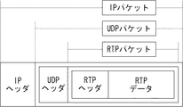
音声や映像などの大量のストリームデータをネットワーク経由で伝送する場合、通常、データを分割し、パケット化して伝送する。このとき、インターネット電話や映像配信サービスなどのように、リアルタイム性が重要となる用途においては、リアルタイム性を確保するために、送信先への到着確認を省略するUDP(User Datagram Protocol)などのプロトコルが用いられている。図4は、インターネット電話におけるデータパケットであるIP(Internet Protocol)パケットの構成を示す図である。IPパケットは、IPヘッダ、UDPヘッダ、RTPヘッダ、RTPデータを含む。RTPパケットは、前記のRTPヘッダとRTPデータからなる。UDPパケットは、前記のUDPヘッダとRTPパケットからなる。UDPは、接続の確立を要さず、パケットを次々に送出することが可能であるため、通話音声を送るなどのリアルタイムな通信に適している。
しかしながら、送信元の装置から次々に送出されるUDPパケットは、送出された順に送信先のインターネット電話装置に到着するとは限らず、途中の通信経路の状況により、順番が入れ替わったり、消失したりすることがある。このような場合であっても、データの品質をできる限り損なわず、かつ、リアルタイムな再生を可能とする技術が求められる。 However, UDP packets sent one after another from the transmission source device do not always arrive at the transmission destination Internet telephone device in the order of transmission, and the order may be changed or lost depending on the state of the communication path on the way. Sometimes. Even in such a case, there is a need for a technique that can reproduce data in real time without losing data quality as much as possible.
本発明はこうした状況に鑑みてなされたものであり、その目的は、順序を有する一連のパケット群を受信し、適切かつ効率的に処理する技術を提供することにある。 The present invention has been made in view of such a situation, and an object of the present invention is to provide a technique for receiving a series of packets having an order and appropriately and efficiently processing them.
本発明のある態様は、通信装置に関する。この通信装置は、順序を有する一連のパケット群を受信する受信手段と、前記順序に関する情報を取得する取得手段と、前記パケット群のデータをメモリに格納する際に、前記パケットのデータが前記メモリにおいて順序通りに配列するように、前記順序を反映した書込みアドレスを生成する書込みアドレス生成手段と、を備えることを特徴とする。 One embodiment of the present invention relates to a communication device. The communication apparatus includes: a receiving unit that receives a series of packet groups having an order; an acquisition unit that acquires information about the order; and the data of the packet is stored in the memory when the data of the packet group is stored in the memory. And write address generating means for generating a write address reflecting the order so as to arrange them in order.
このような構成によれば、音声や映像などのストリーミングデータを、順次を有する一連のパケット群として伝送するときに、受信したパケットの順番が入れ替わっている場合であっても、メモリ上で順序通りに再配列させることができるので、読み出し時のメモリアクセスを高速化することができる。また、パケットの順序を入れ替える処理の負荷を低減することができる。 According to such a configuration, when streaming data such as audio and video is transmitted as a series of sequential packet groups, even if the order of received packets is changed, the order of the data is kept on the memory. The memory access at the time of reading can be increased. In addition, it is possible to reduce the processing load for changing the order of packets.
前記メモリは、前記順序に関する情報をタグとしてアクセスする連想メモリにより構成されてもよい。前記取得手段は、前記パケットのヘッダ情報を参照して、前記順序に関する情報を取得してもよい。 The memory may be an associative memory that accesses information related to the order as a tag. The acquisition unit may acquire information related to the order with reference to header information of the packet.
通信装置は、前記メモリから前記パケットのデータを読み出す際に、順序通りに配列されたパケットのデータを読み出すために、読出しアドレスを順次インクリメントする読出しアドレス生成手段を更に備えてもよい。 The communication device may further include a read address generation unit that sequentially increments a read address in order to read the packet data arranged in order when reading the packet data from the memory.
通信装置は、所定の時点よりも過去の順序のパケットを受信したときに、前記メモリに格納せずに破棄してもよい。通信装置は、既に読み出されたパケットよりも過去の順序のパケットを受信したときに、前記メモリに格納せずに破棄してもよい。これにより、メモリを効率良く利用することができる。 The communication apparatus may discard the packet without storing it in the memory when receiving a packet in an order earlier than a predetermined time. When the communication device receives a packet in an order earlier than a packet that has already been read, the communication device may discard the packet without storing it in the memory. Thereby, the memory can be used efficiently.
前記メモリは、前記パケットのデータの書込み及び読出しの状況を示すフラグ情報を格納する領域を含んでもよい。このフラグ情報により、書込み処理と読出し処理の対応が実現され、同期メモリ方式のアクセスが可能となる。前記パケットのデータが前記メモリに正常に書き込まれたときに、前記フラグ情報として、正常に書き込まれた旨の情報が格納されてもよい。前記メモリは、前記パケットのデータを読み出すときに、そのパケットのデータが前記メモリに格納されていない場合に、そのデータを補完するための補完データのアドレスを格納する領域を含んでもよい。前記パケットのデータを読み出すときに、前記フラグ情報として、正常に書き込まれた旨の情報が格納されていない場合は、前記補完データを読み出してもよい。これにより、データが欠落している場合であっても、データの品質を向上させることができる。 The memory may include an area for storing flag information indicating a state of writing and reading data of the packet. With this flag information, correspondence between the writing process and the reading process is realized, and synchronous memory access is possible. When the packet data is normally written in the memory, information indicating that the packet data has been normally written may be stored as the flag information. The memory may include an area for storing an address of complementary data for complementing the data when the packet data is not stored in the memory when the packet data is read. When the data of the packet is read, if the information indicating that it has been normally written is not stored as the flag information, the complementary data may be read. Thereby, even if data is missing, the quality of data can be improved.
前記パケットのデータを読み出すときに、前記フラグ情報として、正常に書き込まれた旨の情報が格納されていない場合は、前記フラグ情報として、読み出しエラーを示す情報が格納されてもよい。前記パケットのデータを書き込むときに、前記フラグ情報として、読み出しエラーを示す情報が格納されている場合は、そのパケットのデータを前記メモリに格納せずに破棄してもよい。 When the data of the packet is read, if the information indicating that the data has been normally written is not stored as the flag information, information indicating a read error may be stored as the flag information. When information indicating a read error is stored as the flag information when the packet data is written, the packet data may be discarded without being stored in the memory.
通信装置は、前記メモリから前記パケットのデータを読み出すときに、そのパケットのデータが前記メモリに格納されていない場合に、そのデータを補完するための補完データを予め生成する補完データ生成部を更に備えてもよい。前記補完データ生成部は、既に受信したパケットのデータに基づいて、前記補完データを生成してもよい。これにより、補完データの品質を向上させることができる。 The communication device further includes a complementary data generation unit that previously generates complementary data for complementing the data when the packet data is not stored in the memory when the packet data is read from the memory. You may prepare. The complementary data generation unit may generate the complementary data based on already received packet data. Thereby, the quality of complementary data can be improved.
通信装置は、前記補完データ生成部が生成した補完データを格納する補完データ格納部を更に備え、前記パケットのデータを読み出すときに、前記フラグ情報として、正常に書き込まれた旨の情報が格納されていない場合は、前記補完データ格納部に格納された補完データを読み出してもよい。 The communication device further includes a complementary data storage unit that stores the complementary data generated by the complementary data generation unit, and when reading the data of the packet, information indicating that the data has been normally written is stored as the flag information. If not, the complementary data stored in the complementary data storage unit may be read.
なお、以上の構成要素の任意の組合せ、本発明の表現を方法、装置、システムなどの間で変換したものもまた、本発明の態様として有効である。 It should be noted that any combination of the above-described constituent elements and a representation of the present invention converted between a method, an apparatus, a system, etc. are also effective as an aspect of the present invention.
本発明によれば、順序を有する一連のパケット群を受信し、適切かつ効率的に処理する技術を提供することができる。 According to the present invention, it is possible to provide a technique for receiving a series of packets having an order and processing them appropriately and efficiently.
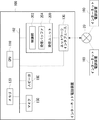
図1は、本発明の実施の形態に係る通信装置の一例としてのインターネット電話装置100の全体構成を示す。インターネット電話装置100は、インターネット20を介して、他のインターネット電話装置100との間で通話を行うための装置である。インターネット電話装置100は、主に、ソフトウェア処理を実行するための汎用回路であるCPU110、プログラムエリアまたはワークエリアとして利用されるメモリ120、インターネット20を介してパケットを送受信する受信手段の一例であるネットワークインタフェース130、ネットワークインタフェース130が受信したパケットを一時的に格納する受信ユニット200、音声信号を入力するマイク150、音声信号を出力するスピーカ160、及びこれらの構成を電気的に接続するバス102を備える。
FIG. 1 shows an overall configuration of an
本実施の形態のインターネット電話装置100では、RTP(Real-time Transport Protocol)を利用して音声信号を送受信する。RTPは、オーディオやビデオなどのデータストリームをリアルタイムに配送することを目的として定められたデータ転送プロトコルである。RTPは、接続の確立を要さず、パケットを次々に送出することが可能なUDPタイプのデータ転送プロトコルであるため、プロトコル処理が簡単で、かつ高速な通信が可能であり、通話音声を送るなどのリアルタイムな通信に適している。しかしながら、送信元の装置から次々に送出されるRTPパケットは、送出された順にインターネット電話装置100に到着するとは限らず、途中の通信経路の状況により、順番が入れ替わったり、消失したりすることがある。
従来、受信側の装置では、データの順番を整列させたり、欠落したデータを補完したりするために、一定時間分のデータを保持するための十分な大きさを有する受信バッファを設ける必要があった。また、データの整列や補完などの処理を、CPU又はDSPなどにより実行されるソフトウェアにより実現する場合、CPUやDSPなどの処理負荷が大きくなるという問題があった。このような処理をリアルタイムに実行するために、処理能力の高いCPU又はDSPを搭載すると、装置のコストが増大するという問題があり、コストを抑えるために比較的処理能力の低いCPU又はDSPを搭載すると、処理が追随できずにリアルタイム性が損なわれるという問題がある。また、後者の場合に、リアルタイム性を確保するために、データの入れ替わりや欠落を無視して処理すると、データの品質が低下するという問題がある。 Conventionally, a receiving apparatus has to provide a reception buffer having a sufficient size to hold a certain amount of data in order to arrange the order of data or to supplement missing data. It was. Further, when processing such as data alignment or complementation is realized by software executed by a CPU or DSP, there is a problem that a processing load on the CPU, DSP, etc. increases. In order to execute such processing in real time, if a CPU or DSP having a high processing capacity is installed, there is a problem that the cost of the apparatus increases, and a CPU or DSP having a relatively low processing capacity is installed to suppress the cost. Then, there is a problem that the processing cannot follow and the real-time property is impaired. Further, in the latter case, there is a problem that the quality of the data is deteriorated if processing is performed while ignoring the replacement or omission of data in order to ensure real-time performance.
本実施の形態では、受信したRTPパケットを適切かつ効率的に処理するために、受信ユニット200への格納時にパケットの順番を入れ替えて順序通りに整列させたり、消失したデータを補完したりするための技術を提案する。
In the present embodiment, in order to appropriately and efficiently process the received RTP packet, the order of the packets is changed when stored in the receiving
まず、インターネット電話装置100がパケットを受信したときの動作の概要について説明する。ネットワークインタフェース130が受信したパケットは、受信ユニット200に一時的に格納される。受信ユニット200に待避されたパケットは、CPU110により順次読み出されて処理される。具体的には、CPU110は、パケットが自装置に割り当てられたIPアドレスに宛てられたものであるか否かを判断して、他装置宛のパケットを破棄し、自装置宛てのパケットのみを次の処理へ移す。つづいて、CPU110は、ヘッダ情報などからパケットの種別を判断して、それぞれのパケットに対して必要な処理を実行する。受信したパケットが音声信号を含むRTPパケットであった場合、CPU110は、圧縮符号化されていた通話音声信号を復号し、スピーカ160に出力する。
First, an outline of the operation when
上述の例では、ネットワークインタフェース130が受信したパケットを、まず受信ユニット200に待避した後、CPU110により読み出して処理したが、別の例では、CPU110又はネットワークインタフェース130が、受信したパケットのヘッダなどをチェックして必要な処理を行ってから、パケットを受信ユニット200に待避してもよい。この場合、RTPパケットのみを受信ユニット200に格納するようにしてもよい。
In the above example, the packet received by the
つづいて、インターネット電話装置100が音声信号を含むデータを送信するときの動作の概要について説明する。マイク150から入力された音声信号は、CPU110により符号化され、必要に応じて暗号化された後、パケット化される。生成されたRTPパケットは、ネットワークインタフェース130を介して、インターネット20に送出される。
Next, an outline of an operation when
上述した例では、パケットの処理をCPU110が行ったが、別の例では、専用のハードウェアによりパケットを処理してもよい。例えば、インターネット電話装置100は、IPによる通信のための各種処理を行うIP処理部、UDPによる通信のための各種処理を行うUDP処理部、音声信号の圧縮符号化処理および復号処理を行うコーデック処理部、暗号化された受信データの復号処理又は送信データの暗号化処理を行う暗号処理部などを備えてもよく、これらの機能ブロックは、専用のハードウェア回路により実現されてもよい。これにより、データの処理を高速化し、リアルタイム性を向上させることができる。
In the example described above, the
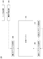
図2は、受信ユニット200の内部構成を示す。受信ユニット200は、受信したパケットを一時的に格納する受信バッファ204と、受信バッファ204に対するデータの書き込み及び読み出しを制御する制御部202を含む。制御部202は、取得手段の一例であるヘッダ抽出部210及び識別子抽出部220と、書込みアドレス生成部230と、読出しアドレス生成部240と、読出しアドレス更新部250とを含む。制御部202は、受信バッファ204と同じチップ上に構成された回路により実現されてもよい。これにより、CPU110を介さずに、受信したRTPパケットを順序通りに再配列させて受信バッファ204に格納することができるので、CPU110の負荷を大幅に軽減することができる。
FIG. 2 shows an internal configuration of the receiving
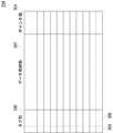
図3は、受信バッファ204のデータ構造を示す。受信バッファ204は、識別子抽出部220により抽出された順序に関する情報をタグとしてアクセスする連想メモリにより構成されており、タグ部300、データ格納部302、及びポインタ部304を含む。タグ部300には、順序に関する情報308とフラグ306が格納される。フラグ306は、データの書き込み状況を示し、受信したパケットのデータがデータ格納部302に正常に格納されると書込みフラグがセットされ、データが正常に読み出されると書込みフラグがクリアされる。また、後述するように、データ格納部302にデータが格納されていないときに読出しが行われると、読出しエラーフラグがセットされる。ポインタ部304は、パケットが通信途中で破棄されていたり、遅延しているなどの理由により、読出し時にデータ格納部302にデータが格納されていないときに、代わりに挿入される代替データのアドレスを保持する。
FIG. 3 shows the data structure of the
図2に戻り、受信ユニット200の他の構成の説明を続ける。ヘッダ抽出部210は、受信したRTPパケットからヘッダ情報を抽出する。図4に示すように、RTPパケットは、UDPパケットのデータ部に格納されており、その先頭にRTPヘッダが格納されている。図5に、RFC1889において規定されたRTPヘッダの構成を示す。RTPヘッダは、RTPのバージョン番号V(RFC1889では「2」)、調整用ビット(パディング)P、拡張ビットX、貢献ソース識別子の数CC、マーカM、ペイロードタイプPT、シーケンスナンバー、タイムスタンプ、同期ソース(SSRC)識別子、及び貢献ソース(CSRC)識別子を含む。ヘッダ抽出部210は、このRTPヘッダを抽出する。識別子抽出部220は、RTPヘッダ中のシーケンスナンバー又はタイムスタンプを抽出する。シーケンスナンバーは、データを順番通りに再構成するために、又は、パケットの損失を検出するために、RTPヘッダに格納される情報である。タイムスタンプは、RTPパケットに含まれるデータの時間情報を示す。
Returning to FIG. 2, description of another configuration of the receiving
書込みアドレス生成部230は、識別子抽出部220が抽出したシーケンスナンバー又はタイムスタンプ情報を参照して、受信バッファ204においてRTPパケットがデータの順序通りに配列して格納されるように、受信バッファ204に対するデータの書込みアドレスを生成する。したがって、RTPパケットが順序通りに到着しなかった場合であっても、受信バッファ204には、RTPパケットが順序通りに配列されて格納される。これにより、受信バッファ204からデータを読み出す時に、メモリアクセスのオーバーヘッドを低減し、読み出しに要する時間を短縮することができるので、データの読出しを高速化することができ、ひいてはストリームデータの再生のリアルタイム性を向上させることができる。書込みアドレス生成部230により生成された書込みアドレスに、パケットのデータが正常に格納されると、正常に書込みが行われたことを示す書込みフラグがフラグ306に格納される。
The write
ストリームデータをリアルタイムに再生するために、ストリームデータの全てを格納可能なサイズの受信バッファ204を用意するのは効率的ではない。本実施の形態では、受信バッファ204をサイクリックに利用することにより、比較的小容量の受信バッファ204を利用してリアルタイムな再生を可能とする。すなわち、既に再生が終わったデータの格納領域は所定のタイミングでリフレッシュし、後続のパケットのデータの格納領域として利用する。
In order to reproduce the stream data in real time, it is not efficient to prepare the
この場合、あるパケットを受信してデータを受信バッファ204に格納した後に、そのアドレスに過去に格納されるはずであったパケットが、いわゆる「周回遅れ」で到着した場合、遅延して到着したパケットが上書きされる恐れがある。このような事態を避けるために、書込みアドレス生成部230は、所定の時点よりも過去の順序のパケットを受信したときに、そのパケットを受信バッファ204に格納せずに破棄してもよい。「所定の時点」は、現在再生中のデータの順序(時間)であってもよい。ストリームデータを再生しているとき、現在再生中のデータよりも過去のデータを含むパケットが遅延して到着した場合、そのデータは再生されないので破棄してもよい。これにより、これから再生されるデータが、遅延して到着した過去のデータに上書きされて失われてしまう事態を回避することができる。ストリームデータが、例えばMPEG4などでエンコードされている場合、現在再生中のフレーム(ピクチャ)よりも過去のデータであっても、復号時に参照されるフレームであれば、破棄せずに受信バッファ204に格納してもよい。この場合、「所定の時点」は、現在再生中のデータの順序を基点として、1又は数GOP分過去の時点であってもよい。書込みアドレス生成部230は、データを読み出し中の読出しアドレスを取得して、その読出しアドレスに格納されたパケットよりも過去の順序のパケットを破棄してもよい。また、書込みアドレス生成部230は、所定時間以上遅延して到着したパケットを破棄してもよい。
In this case, after a packet is received and data is stored in the
書込みアドレス生成部230は、所定のサイズの書込みウィンドウを設定し、その書込みウィンドウ内に格納されるべきパケット以外のパケットを受信したときには、そのパケットを受信バッファ204に格納せずに破棄してもよい。書込みウィンドウは、例えば、既に読み出されて再生が終わったパケットのアドレスを開始アドレスとして、パケットのサイズ、受信レート、再生レート、受信バッファ204のサイズなどに基づいて決定されたサイズの領域に設定されてもよい。ストリームデータをリアルタイムに再生しているとき、既に再生が終わったデータを含むパケットが遅延して到着しても、そのパケットは再生されないので、受信バッファ204に格納せずに破棄してもよい。これにより、インターネット電話装置100の処理負荷が低減されるとともに、受信バッファ204を効率良く利用することができる。
The write
読出しアドレス生成部240は、データの読出し要求を受け付けると、データの先頭のアドレスを生成する。読出しアドレス更新部250は、読出しアドレスを1データ分インクリメントするよう読出しアドレス生成部240に指示してもよい。読出しアドレス生成部240は、以降、読出しアドレス更新部250からの指示に従い、順次読出しアドレスを1データ分ずつインクリメントしてもよい。これにより、受信バッファ204に順序通りに格納されたデータを順次読み出すことができる。データがデータ格納部302から正常に読み出されると、フラグ306の書込みフラグがクリアされる。
When receiving a data read request, the read
インターネット電話装置100は、パーソナルコンピュータなどとは異なり、比較的処理性能の低いCPUを搭載してコストを抑える場合が多いが、本実施の形態の技術によれば、処理性能の低いCPUであっても、通話音声データを含むパケットを効率よく処理し、リアルタイムに再生することが可能となる。また、CPU110に余力ができるため、通話中に他のアプリケーションを実行することが可能となり、新たなサービスを提供することもできる。
Unlike the personal computer or the like, the
制御部202の構成は、ハードウエア的には、任意のコンピュータのCPU、メモリ、その他のLSIで実現でき、ソフトウエア的にはメモリにロードされたプログラムなどで実現できる。図2では、それらの連携によって実現される機能ブロックを描いているので、これらの機能ブロックがハードウエアのみ、ソフトウエアのみ、またはそれらの組合せによっていろいろな形で実現できることは、当業者には理解されるところである。
The configuration of the
図6は、受信バッファ204のポインタ部304の設定例を示す。ポインタ部304は、前述したように、RTPパケットが通信途中で遅延したり、破棄されたり、破壊されたりして、正しいデータが受信できなかった場合、その部分のデータを補完する他のデータへのポインタを格納する。データを読み出すときに、そのデータが未受信であったり、破壊されていた場合は、ポインタ部304に格納されたアドレスに存在する補完データが代わりに読み出される。これにより、パケットが遅延したり、通信経路で廃棄されたりして、データが正しく受信できなかった場合であっても、適切にデータを補完することができ、データの品質を向上させることができる。
FIG. 6 shows a setting example of the
補完データとしては、例えば、1つ前のデータであってもよいし、所定位置のデータであってもよいし、補間データ生成部260により生成された補間データであってもよい。ここで、「補完」は、欠落したデータを補って完全にすることをいい、固定的に定められたデータで補ってもよいし、計算により導かれたデータで補ってもよい。所定の規則にしたがって算出されたデータで補う場合は、「補間」といってもよく、ここでは、その意味で、「補間データ生成部260」と呼んでいる。補間データ生成部260は、過去に受信したデータに基づいて、所定のアルゴリズムにより補間データを算出する。補間データ生成部260は、例えば、過去に受信したデータの平均値を算出して補間データを生成してもよいし、過去に受信したデータの最大値、最小値、中央値、最頻値、などにの統計値に基づいて補間データを生成してもよい。補間データ生成部260が生成した補間データは、補間データ格納部270に格納される。補間データ生成部260は、CPU110などにより実現されてもよい。補間データ格納部270は、メモリ120に設けられてもよいし、受信ユニット200内に設けられてもよい。
The complementary data may be, for example, the previous data, data at a predetermined position, or interpolation data generated by the interpolation
補完データが読み出されたとき、そのデータの格納領域のフラグ306に読出しエラーフラグがセットされる。書込みアドレス生成部230は、エラーフラグが既にセットされているデータを含むパケットを受信したとき、そのデータは既に補完データにより補完されて再生されているので、そのパケットを受信バッファ204に格納せずに破棄する。これにより、無用な処理を省き、処理負荷を低減することができる。エラーフラグは、受信バッファ204の格納領域をリフレッシュするときにクリアされる。このとき、ポインタ部304には、デフォルト値として、所定のアドレス、例えば補間データ格納部270のアドレスが格納されてもよい。
When complementary data is read, a read error flag is set in the
以上、本発明を実施の形態をもとに説明した。この実施の形態は例示であり、それらの各構成要素や各処理プロセスの組合せにいろいろな変形例が可能なこと、またそうした変形例も本発明の範囲にあることは当業者に理解されるところである。 The present invention has been described based on the embodiments. This embodiment is an exemplification, and it will be understood by those skilled in the art that various modifications can be made to combinations of the respective constituent elements and processing processes, and such modifications are also within the scope of the present invention. is there.
実施の形態では、通信装置の一例としてインターネット電話装置について説明したが、本実施の形態の技術は、ルータ、パーソナルコンピュータ、テレビジョン受信装置など、順序を有する一連のパケット群を受信可能な任意の装置に適用可能である。 In the embodiment, the Internet telephone device has been described as an example of the communication device. However, the technology of the present embodiment can be used for any arbitrary packet group that can receive a sequence of packets such as a router, a personal computer, and a television receiver. Applicable to the device.
100 インターネット電話装置、110 CPU、120 メモリ、130 ネットワークインタフェース、200 受信ユニット、202 制御部、204 受信バッファ、210 ヘッダ抽出部、220 識別子抽出部、230 書込みアドレス生成部、240 読出しアドレス生成部、250 読出しアドレス更新部、260 補間データ生成部、270 補間データ格納部、300 タグ部、302 データ格納部、304 ポインタ部、306 フラグ、308 アドレス。 100 Internet telephone apparatus, 110 CPU, 120 memory, 130 network interface, 200 reception unit, 202 control unit, 204 reception buffer, 210 header extraction unit, 220 identifier extraction unit, 230 write address generation unit, 240 read address generation unit, 250 Read address update unit, 260 interpolation data generation unit, 270 interpolation data storage unit, 300 tag unit, 302 data storage unit, 304 pointer unit, 306 flag, 308 address.
Claims (15)
前記順序に関する情報を取得する取得手段と、
前記パケット群のデータをメモリに格納する際に、前記パケットのデータが前記メモリにおいて順序通りに配列するように、前記順序を反映した書込みアドレスを生成する書込みアドレス生成手段と、
を備えることを特徴とする通信装置。 Receiving means for receiving a series of packets having an order;
Obtaining means for obtaining information on the order;
A write address generating means for generating a write address reflecting the order so that the data of the packet is arranged in order in the memory when storing the data of the packet group in the memory;
A communication apparatus comprising:
前記パケットのデータを読み出すときに、前記フラグ情報として、正常に書き込まれた旨の情報が格納されていない場合は、前記補完データ格納部に格納された補完データを読み出すことを特徴とする請求項13又は14に記載の通信装置。 A complementary data storage unit for storing the complementary data generated by the complementary data generation unit;
The complementary data stored in the complementary data storage unit is read when information indicating that the packet has been normally written is not stored as the flag information when reading the data of the packet. The communication device according to 13 or 14.
Priority Applications (1)
| Application Number | Priority Date | Filing Date | Title |
|---|---|---|---|
| JP2004027403A JP4201719B2 (en) | 2004-02-03 | 2004-02-03 | Communication device |
Applications Claiming Priority (1)
| Application Number | Priority Date | Filing Date | Title |
|---|---|---|---|
| JP2004027403A JP4201719B2 (en) | 2004-02-03 | 2004-02-03 | Communication device |
Publications (2)
| Publication Number | Publication Date |
|---|---|
| JP2005223459A JP2005223459A (en) | 2005-08-18 |
| JP4201719B2 true JP4201719B2 (en) | 2008-12-24 |
Family
ID=34998780
Family Applications (1)
| Application Number | Title | Priority Date | Filing Date |
|---|---|---|---|
| JP2004027403A Expired - Fee Related JP4201719B2 (en) | 2004-02-03 | 2004-02-03 | Communication device |
Country Status (1)
| Country | Link |
|---|---|
| JP (1) | JP4201719B2 (en) |
-
2004
- 2004-02-03 JP JP2004027403A patent/JP4201719B2/en not_active Expired - Fee Related
Also Published As
| Publication number | Publication date |
|---|---|
| JP2005223459A (en) | 2005-08-18 |
Similar Documents
| Publication | Publication Date | Title |
|---|---|---|
| TWI419565B (en) | Method for buffering media stream packets, system for buffering media streams, devices for transmitting and chipsets, servers, and computer program products | |
| CN101867692B (en) | Communication method and communication system | |
| CN109889535B (en) | Method and apparatus for media data delivery control | |
| JP2009512279A (en) | Media data processing using different elements for streaming and control processing | |
| CN102595199A (en) | Streaming media packet packaging and transmitting method, and streaming media processing device | |
| US20190110091A1 (en) | Method and device for synchronously performing an operation on contents | |
| CN101271720A (en) | A method for synchronizing mobile phone streaming audio and video | |
| CN102118292A (en) | Internet protocol multimedia subsystem (IMS) network as well as data transmission method and device | |
| CN115209163B (en) | Data processing method and device, storage medium and electronic equipment | |
| JP2003224839A (en) | Streaming system and streaming method, streaming server and data distribution method, client terminal and data decoding method, authoring apparatus and authoring method, and program and recording medium | |
| JP5344541B2 (en) | Data transmission apparatus, transmission method and program | |
| JP4600513B2 (en) | Data transmission apparatus, transmission rate control method, and program | |
| US9723610B2 (en) | Multi-layer timing synchronization framework | |
| CN109714295B (en) | Voice encryption and decryption synchronous processing method and device | |
| CN113612962B (en) | Video conference processing method, system and device | |
| JP4201719B2 (en) | Communication device | |
| KR20160123562A (en) | Receiver for processing data packet and data packet processing method of receiver | |
| JP2002152301A (en) | Data communication system, data receiving device, data communication method, and program storage medium | |
| US11671976B2 (en) | Early notification for transmission of encoded video data | |
| US7894486B2 (en) | Method for depacketization of multimedia packet data | |
| CN106534137B (en) | Media stream transmission method and device | |
| Fonnes | Reducing packet loss in real-time wireless multicast video streams with forward error correction | |
| US20250294068A1 (en) | Methods and Systems for Real-Time Content and Controls Streaming | |
| JP4636896B2 (en) | STREAM DATA REPRODUCING DEVICE, STREAM DATA REPRODUCING PROGRAM, AND STREAM DATA REPRODUCING METHOD | |
| WO2025191503A1 (en) | Methods and systems for real-time content and controls streaming |
Legal Events
| Date | Code | Title | Description |
|---|---|---|---|
| A621 | Written request for application examination |
Free format text: JAPANESE INTERMEDIATE CODE: A621 Effective date: 20060905 |
|
| A977 | Report on retrieval |
Free format text: JAPANESE INTERMEDIATE CODE: A971007 Effective date: 20080827 |
|
| TRDD | Decision of grant or rejection written | ||
| A01 | Written decision to grant a patent or to grant a registration (utility model) |
Free format text: JAPANESE INTERMEDIATE CODE: A01 Effective date: 20080909 |
|
| A01 | Written decision to grant a patent or to grant a registration (utility model) |
Free format text: JAPANESE INTERMEDIATE CODE: A01 |
|
| A61 | First payment of annual fees (during grant procedure) |
Free format text: JAPANESE INTERMEDIATE CODE: A61 Effective date: 20081007 |
|
| FPAY | Renewal fee payment (event date is renewal date of database) |
Free format text: PAYMENT UNTIL: 20111017 Year of fee payment: 3 |
|
| FPAY | Renewal fee payment (event date is renewal date of database) |
Free format text: PAYMENT UNTIL: 20121017 Year of fee payment: 4 |
|
| FPAY | Renewal fee payment (event date is renewal date of database) |
Free format text: PAYMENT UNTIL: 20121017 Year of fee payment: 4 |
|
| FPAY | Renewal fee payment (event date is renewal date of database) |
Free format text: PAYMENT UNTIL: 20131017 Year of fee payment: 5 |
|
| LAPS | Cancellation because of no payment of annual fees |