JP4201539B2 - File - Google Patents
File Download PDFInfo
- Publication number
- JP4201539B2 JP4201539B2 JP2002201995A JP2002201995A JP4201539B2 JP 4201539 B2 JP4201539 B2 JP 4201539B2 JP 2002201995 A JP2002201995 A JP 2002201995A JP 2002201995 A JP2002201995 A JP 2002201995A JP 4201539 B2 JP4201539 B2 JP 4201539B2
- Authority
- JP
- Japan
- Prior art keywords
- file
- handle
- opening
- spine
- cover member
- Prior art date
- Legal status (The legal status is an assumption and is not a legal conclusion. Google has not performed a legal analysis and makes no representation as to the accuracy of the status listed.)
- Expired - Lifetime
Links
Images


Description
【0001】
【発明の属する技術分野】
本発明は、書類等を綴じて保管又は使用する綴じ具を備えたファイルに関するものである。
【0002】
【従来の技術】
近年、オフィスなどで用いられる、表裏一対の開閉表紙部と、これら開閉表紙部の基端間に設けた背表紙部と、この背表紙部の内面又は開閉表紙部の基端部近傍内面に取り付けた綴じ具とを有したファイルにおいて、前記背表紙部に当該背表紙部の表面(背面)から突出して手で把持可能な取手部材を取り付けるようにして、書棚などに複数並列して収納された状態からスムーズに取り出すことが可能であり、さらに持ち運びにも好都合となるようにしたものが開発されている。
【0003】
さらに、このような取手部材を取り付けて構成したファイルにおいて、この取手部材が背表紙部の表面から浮いてしまい、背表紙部の外観を損ねてしまうという不具合を解決するものとして、例えば、背表紙部に当該背表紙部の表面より凹ませた取手収容部を形成して、不用時には、その取手収容部に取手部材を収容させて表面より突出させないようにするものも考えられている。
【0004】
【発明が解決しようとする課題】
しかしながら、このようなものであると、通常、取手部材は使用時のバランスを考慮して背表紙部の中央部に設定されるため、背表紙部に配置される見出し片が上下に分断されることになってしまう。書棚等に背表紙部を手前側へ向けて配置させることになるファイルにとって、前記綴じ具に綴じている書類等の内容を示す見出し片は極めて重要であり、見出し片が分断されて小さいものとなってしまうのは不都合である。
【0005】
一方、背表紙部の上下に手指を引っ掛けられるような凹部を形成して、見出し片を装着する領域を上下方向に沿って確保するようなものの考えられているが、このようなものは、ファイルを把持するバランスが悪く、書棚などから引き出すことは可能であっても、このような凹部を把持してファイルを持ち運ぶことは、現実的には困難である。
【0006】
そこで、上記のような不具合を解決するべく、ファイルの美観を損ねず、なお且つバランス良く把持できる取手を備えるとともに、背表紙部の中央部に上端部近傍から下端部近傍に亘って見出し片を取り付ける領域を確保することが可能な使用勝手の良好な新しいファイルを提供する。
【0007】
【課題を解決するための手段】
すなわち、本発明のファイルは、表裏一対の開閉表紙部と、これら開閉表紙部の基端間に設けた背表紙部と、この背表紙部の内面又は開閉表紙部の基端部近傍内面に設けられ書類等の被綴込体を綴じる綴じ具とを具備するものであって、前記背表紙部の上下方向における中央部を少なくとも含み且つ少なくとも一方の側端部近傍に形成される開口を通じて当該開口に連続する凹部内に手指を差し入れて把持し得る取手を設けていることを特徴とする。なお、「上下方向における中央部」とは、上下方向の中央の周辺部を指している。
【0008】
このようなものファイルであれば、当該ファイルに設けた取手によって背表紙側の上下方向における中央部を把持することができるようになる。また、この取手は、凹部を利用したものであるため、別体の取手部材を取り付けるようなもののように背表紙部から外方へ表出せず、ファイルの外観を損ねるのを防ぐことが可能となる。さらに、開口及び取手に干渉されることなく上端部近傍から下端部近傍に亘って連続する見出し片を装着する領域を確保することができるようになる。さらに、開口を形成する位置調整さえ行えば、その見出し片を、背表紙部の幅方向(左右方向)における中央部に装着してさらに見易くなるように構成することも可能となる。すなわち、収納状態からの引き出しや持ち運び等の場合に好適なものであり、しかも把持した際の重量バランスが良好でなお且つファイルの美観を保つ取手と、背表紙部の上端部から下端部側に亘る見易い見出し片とを共に兼ね備え使用勝手を向上させた新しいファイルを提供することができるようになる。
【0009】
また、このようなファイルとして、例えば背表紙部の上下方向における中央部を含んでさらにその上下に延びるような開口が形成され、取手が背表紙部の上下に亘って延びるようなものであってもよいが、背表紙部の強度を確保するためには、開口及び取手を上下方向における中央部のみに設けるようにすれば好ましい。
【0010】
また、左右どちらの手指にも対応でき、また安定した状態で把持できるようなものとするためには、開口を、記背表紙部の上下方向における中央部の両側端部近傍に形成するようにして、取手を左右両側端部側から手指を差し入れることができるように形成することが望ましい。
【0011】
また、本発明を適用するファイルが、前記開閉表紙部とこの開閉表紙部の基端間に連続する背部とを備え前記綴じ具が取り付けられるファイル本体と、前記背部を覆うように取り付けられ当該背部と前記背表紙部を構成する背カバー部材とを備えてなるものであれば、元来、綴じ具装着のための固定具やリベットなどを隠蔽し得る効果を備えた背カバー部材を利用することによって、背表紙部の内面の上下方向における中央部に取り付けられる綴じ具と干渉することなく、背表紙部の背面側の上下方向における中央部に取手を設けることができるようになる。特に、背カバー部材がある程度の厚み寸法(前後幅寸法)を有するものであれば、その背カバー部材の厚みを利用して前記凹部を形成し取手を設けることが無理なく可能となる。
【0012】
そして、このようなファイルの好適な具体的態様としては、前記開口を避けて、背表紙部の幅方向における中央部に上下方向に沿って見出し片装着部を形成しているものが挙げられる。このようなものであれば、左右どちら側からでも見出し片を見易くなるからである。
【0013】
また、このように背表紙部を、背部と背カバー部材とによって構成するようにしたものに、取手を設けるようにした場合には、前記取手を、前記ファイル本体と一体成形するようにし、前記開口を、背カバー部材に形成するようにすれば好ましい。背カバー部材側に取手を設けると、持ち運び時に背カバー部材とファイル本体との係合部分に書類等を綴じた状態のファイル本体の荷重が働いて係合が外れてしまう可能性があるが、このようなものであれば、実際、把持するのはファイル本体であるため、前記係合部分が棄損することなく安定した状態で把持できるようになるからである。
【0014】
また、このように取手をファイル本体と一体成形したようなものである場合には、背カバー部材に、背面側に開放される窓部を形成して、この窓部を通じて、前記ファイル本体と一体成形された取手を、背カバー部材の前記窓部を通じて露出させるようにすると望ましい。このようにすれば、取手は、窓部を構成する背カバー部材の壁部の厚み寸法分だけ背面側へ位置付けることが可能となり、すなわち、この壁部の厚み寸法を、手指を差し入れる凹部の厚み寸法に加えることができる。その結果、背カバー部材の厚み寸法の短寸化、ひいてはファイルの奥行き幅(前後方向における長さ)の短寸化できるようになり、ワゴンの引出し等の閉塞された収納空間に収納する場合、特に開閉自由端部を下方に位置付けるようにした場合に都合がよい。そして、取手を、前記窓部を通じてこの窓部の周辺部とほぼ面一をなすように表出させるようにすれば、この窓部に跨って見出し片を取り付けた場合であっても、見出し片を装着しやすく、また見出し片に凹凸形状が生じず外観上好ましい。
【0015】
さらに、凹部の厚み寸法を大きくとれるようにして背カバー部材の厚みを可及的に小さくするためには、前記背部に当該凹部に連続して空間を形成するような当該背部の肉厚を貫通させた孔又は背部を窪ませた穴を形成することが望ましい。そして、このような背部を貫通させた孔又は背部を窪ませた穴を、取手を成形する際の抜き加工によって形成されるものとすれば、製作の利便性を図ることができるようになる。
【0016】
また、このように窓部から取手を表出させるように構成したものにおいて、美観を保つためには、見出し片を、この窓部を通じて表出させた取手を隠蔽するように取り付けることが望ましい。そして、このような取手の隠蔽を実現する好適な具体的態様としては、請求項4記載の見出し片装着部を、背カバー部材に、窓部と略同幅寸法を有し、当該窓部を跨いでその上下に延びるように設定するようにしたものが挙げられる。
【0017】
このように取手を備えたファイルの使用勝手をさらに向上させるためには、開平表紙部を、選択的に開成不能に係止する係止部を設けることが望ましい。このようなものであれば、取手を把持して持ち運ぶ場合や棚、ワゴン等に収納する場合などに、開閉表紙部を開成させない状態を維持して所定箇所に収納し易くなり、また持ち運びし易くなる。そして、このような係止部の具体的態様としては、前記開閉表紙部の一部に形成され、開閉表紙部の閉止状態において綴じ具の一部と例えば外方からの操作によって係り合うように構成したものが挙げられる。
【0018】
【発明の実施の形態】
以下、本発明の一実施形態を、図面を参照して説明する。
【0019】
このファイル1は、一対の開閉表紙部2a、2bと、この開閉表紙部2a、2bの基端間に連続する背部2cとを備えたファイル本体2と、このファイル本体2の内面に取り付けた綴じ具3とを備え、ファイル本体2の背部2cに背カバー部材4を取り付けることによって背表紙部Bを構成しているものである。なお、以下に説明する前後方向とは、開閉表紙部2aの開閉自由端部側を前方(図中Fで示している)、そして背表紙部Bが設けられた側を後方(図中Rで示している)とし、上下方向とは、背カバー部材4の長手方向を指すものとする。
【0020】
ファイル本体2は、例えばA4規格やB5規格の書類等の被綴込体を綴じるように対応させた表裏一対の縦長な開閉表紙部2a、2bと、これら開閉表紙部2a、2bの基端部にヒンジ部2dを介して設けられている背部2cとを備えたものであり、例えば合成樹脂などによって成形している。なお、ファイル本体2は、背部2cを略中央部分において上下方向に縦割りした2つのファイル本体要素によって構成されたようなものであってもよい。
【0021】
開閉表紙部2a、2bには、それぞれファイル1を閉成させた状態で綴じ具3の側端面が当設する部分に一対の平面視L字型をなす突条21、21を対向して設けている。そして、この対向する突条21、21の内法寸法を、綴じ具3の外形長さと略一致させるとともに、高さ寸法を、綴じ具3の後述する押さえ板32の厚み寸法と略一致するように設定している。すなわち、ファイル1の閉止状態においてこの綴じ具3の押さえ板32が突条21、21の内部におおよそ位置決めされて収容されるようになっている。そして、この突条21、21の内に綴じ具3の押さえ板32を収容させた状態で、各開閉表紙部2a、2bを開成不能に係止する係止部22を形成している。この係止部22は、突条21、21間の中間部における反綴側に背表紙部Bの長手方向に沿って延びるヒンジ部221と、このヒンジ部221から開閉表紙部2a、2bの基端側に連続して外面視矩形状をなし先端に爪部222aを形成してる係止片222と、この係止片222のヒンジ部221を除く周囲に開閉表紙部2a、2bの肉厚を貫通させた外面視コ字形をなす図示しないスリットとを形成して構成している。
【0022】
この係止片222は、基端部をヒンジ部221に連続させ、先端部を前記スリットにより開放したものであり、その先端部を開閉表紙部2a、2bの閉止状態において押さえ板32と重合する位置に位置付けている。そして、この係止片222全体の形状を、開閉表紙部2a、2bの内面側に緩やかに湾曲して突出するものとしており、その形状に沿って外面側から内面側に窪ませた操作用の凹部223を形成していて、この凹部223に指の腹を当てて押すように操作して押さえ板32に爪部222aを係合するように構成している。
【0023】
また、背部2cには、綴じ具3を固定するための固定具35を取り付けるための取付孔2c1を形成している。さらに、背カバー部材4を装着するためのファイル本体2側の係合部として、背面2caの両側部に一対ずつ上下に設けた突条F11の所定部位に外向きの係合爪F11を間欠的に形成するとともに、上下端部に、内面2cb側に段部F21を備えた係合凹部F2(図6参照)を形成している。
【0024】
綴じ具3は、図4に示すように、例えば、背部2cの内面2cb側に固定されたベース31と、このベース31の左右両側に着脱可能に取り付けられた一対の押さえ板32、32と、各押さえ板32、32から突出し互いに嵌め合う綴じ桿33、34とを具備して前記押さえ板32、32間に書類等の被綴込体を綴じ込むことが可能なものであり、いわゆるチューブ式のものである。なお、図中、判りやすく示すために綴じ桿34を途中で分断して示している。前記ベース31は、ファイル本体2の背部2cに設けた図5、6に示す取付孔2c1によって取り付けられる上下の固定具35、35によって、ファイル本体2の背部2cに取り付けられている。図示例の綴じ具3は、この固定具35によって、リベット等を使用せずに、ベース31をファイル本体2に取り付けられるようなものであるが、ベース31をリベット等で取り付けるタイプのものであってもよい。なお、この綴じ具3の素材としては、例えば金属等が挙げられ、その他合成樹脂によるものであってもよい。
【0025】
背カバー部材4は、前記背部2c幅寸法に略相当する距離離間して後方へ向かって漸次内側へ湾曲する一対の側壁部41a、41bと、この側壁部41a、41bの後端部間に連続し背部2cと略平行をなすように形成された背壁部42と、側壁部41a、41bの前端部間を上下方向における中間部位を接続するように形成された前壁部43(図8参照)と、前記側壁部41a、41b及び背壁部42の上端部及び下端部を覆うように設けられた天壁部44及び底壁部45(図4参照)とを具備してなり、ファイル本体2の背部2cの高さ寸法及び幅寸法と略一致した高さ寸法及び幅寸法に設定した柱状のものである。前記前壁部43の上端部及び下端部には、この前壁部43と背壁部42と連結させる水平方向に延びる壁部431、432(図10参照)を設けて、内部に空洞を有する背カバー部材4の補強となるようにしている。また、前記側壁部41a、41bの前端部に、前記係合爪F1に係合する内向きの係合爪C1を形成するとともに、天壁部44及び底壁部45の前端部に、前記段部F21に対応する段部C21を備え前記係合凹部F2に嵌まり込んで係合する係合凸部C2を形成して、ファイル本体2に固定するための背カバー部材4側の係合部を構成している。なお、この背カバー部材4をファイル本体2に固定するための手段は、その他適宜のものであってよい。
【0026】
しかして、本実施形態においては、前記背表紙部Bを構成する背カバー部材4の両側端部近傍の上下方向における中央部に開口4Ka、4Kbを形成し、この開口4Ka、4Kbを通じて当該開口4Ka、4Kbに連続する凹部5a、5b(図12参照)内に手指を差し入れて把持し得る取手6を設けるとともに、背カバー部材4の幅方向の中央部に上下に延びる見出し装着部7を形成している。具体的には、前記取手6は、ファイル本体2と一体成形により設けるようにしたもので、図2、3、11、12に示すように前記背カバー部材4の背面側に開放される窓部4Wを形成してこの窓部4Wを通じて表出させるようにしている。
【0027】
詳述すれば、まず窓部4Wは、背表紙部Bのほぼ上下方向及び幅方向(左右方向)における中央部に、取手6の外形状の大きさと略一致乃至若干大きく設定して形成したものである。
【0028】
そして、前記背カバー部材4の前壁部43には、取手6が、前記窓部4Wに到達するように、取手6を挿通させる開口43Kを形成している。
【0029】
開口4Ka、4Kbは、背カバー部材4の両側壁部41a、41bと背壁部42とに跨る位置の上下方向における中央部に、側方から手指を差し入れ可能な開口幅に設定して形成したもので、前記窓部4Wを挟むように位置する。そして、この開口4Ka、4Kbは、図11、12に示すように、背壁部42の前記窓部4Wの側縁部分(図中42xで示している)と、前壁部43の開口43Kの側縁部分(図中43xで示している)との間に形成されることになるため、これらの部分42x、43xの開口4Ka、4Kbの開口端側を、アール状に成形して、手指を差し込み易くしている。
【0030】
取手6は、ファイル本体2と一体成形により前記背部2cの背面2caから突出するように形成したもので、手指が接触する部位である把持部61と、この把持部61を背面2aから所定距離後方へ位置付けるように支持し上下方向に延びる支持部62と、これら把持部61及び支持部62の上端部及び下端部に補強となる上壁63及び下壁64とを備えてなり、背表紙部Bの上下方向における中央部のみに設けられている。前記把持部61は、両手で挟み込める程度の幅寸法に設定してある。また、支持部62は、把持部61の幅方向における中央部に接続するもので、その上下方向の長さ寸法は、前記開口4Ka、4Kbとほぼ同じ乃至若干大きく設定してある。これら把持部61と支持部62とは、図11、12に示すように平断面形状(横断面形状)が略T字型をなすように成形される。しかして、前記開口4Ka、4Kbから、把持部61の裏側(前方側に相当)に亘り、左右2つの凹部5a、5bが支持部62を挟んで形成されることになる。また、取手6の背面2caからの突出幅寸法を、背カバー部材4の前後方向の厚み寸法と略一致させて、前記窓部4Wから表出させた取手6が、当該窓部4Wの周辺部に相当する後述する嵌込凹部71とほぼ面一となるようにしている。
【0031】
また、ファイル本体2の背部2cには、図11、12に示すように前記凹部5a、5bに連続して空間を形成するように当該背部2cの肉厚を貫通させた貫通孔2c2が形成されている。この貫通孔2c2は、背面2caから突出させた前記取手6の左右に凹部5a、5bが形成されるように背部2cの内面2cb側への抜き加工によって形成したものである。
【0032】
一方、見出し片装着部7は、例えば紙製等の見出し片Lと透明乃至半透明の樹脂製の見出し片カバーLCとともに装着するように構成しており、嵌込凹部71と、嵌込凹部71に嵌め込んだ見出し片カバーLCに形成された差込片LC1を差し込んで固定する差込孔72と、見出し片L及び見出し片カバーLCを取り出す際に指掛け可能な凹部73とを備えてなる。嵌込凹部71は、背壁部42の背面側を、その上端部から下端部近傍に亘って、前記見出し片Lと見出し片カバーLCとの厚み寸法に対応させて凹ませて形成したものである。そして、この嵌込凹部71は、前記窓部4Wと同幅寸法に設定され当該窓部4Wを跨るように形成したもので、嵌込凹部71と同幅寸法を有する見出し片L及び見出し片カバーLCが前記窓部Wから表出させた取手6を隠蔽するように取り付るようにしている。差込孔72は、前記見出し片カバーLCの外周縁部から突出させた差込片LC1を差し込めるように、嵌込凹部71の外周縁部に形成したものである。凹部73は、背部2cの天壁部44と背壁部42とに連続するように部分球状に凹ませたものである。なお、嵌込凹部71に嵌め込んだ状態の見出し片Lに指掛け可能なものであれば、部分球状には限られない。また、本実施形態の見出し装着部7は、見出し片Lを見出し片カバーLCとともに装着するようなものであるが、見出し片Lのみを凹凸係合や接着など適宜手段で装着するようなものであってもよい。
【0033】
次に、このファイル1を組み立て手順について説明する。まず、ファイル本体2の背部2cの背面2ca側から突出する取手6を、背カバー部材4の窓部4Wから表出するように位置付けるとともに、ファイル本体2の係合爪部F1と、背カバー部材4側の係合爪部C1と一時的に弾性変形させて係合させるとともに、ファイル本体2側の係合凹部F2に背カバー部材4の係合凸部C2を、それぞれの段部F21段部C21とが当接するよう嵌め込んで係合させるようにする。しかして、背カバー部材4は、左右方向、前後方向及び上下方向の位置決めがなされた状態でファイル本体2に取り付けられることとなる。この際、取手6は、図3に示すように嵌込凹部71と面一をなすように窓部4Wから表出している。そして、見出し片L及び見出し片カバーLCを、嵌込凹部71に嵌め込み、差込片LC1を差込孔72に差し込むようにして装着する。
【0034】
以上のように構成した本実施形態におけるファイル1は、背表紙部Bの上下方向における中央部を含んだ両側端部近傍に形成した開口4Ka、4Kbを通じてこの開口4Ka、4Kbに連続する凹部5a、5b内に手指を指し入れて把持できる取手を設けるようにしたので、これら開口4Ka、4Kbや取手6に干渉することなく、幅方向の中央部に上下に亘って延びる取手装着部7を形成することができる。すなわち、このファイル1に幅方向の中央部に所定幅を有して上下に延び見易い見出し片Lを装着することができる。
【0035】
また、本実施形態の取手6は、背表紙部に形成される凹部を利用した立体的な形状をしており、把持する場合には、凹部5a、5bが形成されている背カバー部材4の裏側に手を指し入れた状態で把持することになるので、別体の取手部材を適宜の手段で取り付けたようなものと比較すると、しっかりと把持でき棚やワゴンの引出し内での収納状態から引っ張り出すような場合に安定している。加えて、取手6が背表紙部Bから突出することがないのでファイル1の背面からの外観を損ねることがない。
【0036】
また、取手6を背表紙部Bの上下方向における中央部のみに設けているので、背表紙部Bの上端部から下端部に亘るように設けられたようなものと比較して、背表紙部Bの剛性を低下させない。そして、この取手6は、背表紙部Bの上下方向及び幅方向(左右方向)の中央部に位置するため、バランスよく把持できる。
【0037】
また、開口4Ka、4Kbを両側端部に形成するようにしたので、親指側と人差し指側間で挟んで握るように取手6を把持でき、バランス良く持ち運ぶことができるとともに、右利きの使用者にも左利きの使用者にも対応できる。
【0038】
本実施形態特有の効果としては、ファイル1を背カバー部材4を備えて構成しているので、ファイル本体2の背面2c側に表出する固定具35を隠蔽することができるともに背表紙部Bに強度を確保できるようになり、さらに、この背カバー部材4の厚み寸法を有効に利用して、取手6及び取手6に手指を差し込むための凹部5a、5bを形成することができる。
【0039】
また、ファイル本体2と一体成形によって設けた取手6を把持することによって、書類等が綴じてあるファイル本体2を直接的に持つことになり、背カバー部材4とファイル本体2の係合部分がファイル本体2側の荷重によって外れてしまうことを心配せず、安定した状態でファイル1を持ち上げたり、持ち運んだりできる。
【0040】
また、取手6の突出端側に位置する把持部61を背カバー部材4に形成した窓部4Wから表出させるとともに、取手6の基端側に位置する背部2cに凹部5a、5bと連続する空間を形成する貫通孔2c2を形成したので、凹部5a、5bを厚み寸法(前後幅)を大きくして手指を差し込み易くできる。そして、この結果、背カバー部材4の厚み寸法を、凹部の確保のために大きく設定せずともよく、ファイル1の前後幅を短寸化させることができ、特にワゴンの引出し内など閉塞された空間に収納する場合に都合がよい。また、前記貫通孔2c2を取手6を形成するための抜き加工により形成されるようにしているので、貫通孔2c2を形成するための別途加工を必要とせず、製作の利便性を図ることができる。
【0041】
また、開閉表紙部2a、2bを選択的に開成不能に係止する係止部22を設けたので、収納する場合や、取手6を把持して書棚などから取り出す場合や持ち運ぶような場合には、ファイル1の開閉表紙部2a、2bが開いてしまうのを禁止させることができ使用勝手が良い。
【0042】
なお、本発明は上記実施形態に限られない。
【0043】
例えば、図13、14に示すような、上記実施形態と略同様の基本構成を有し一部の構成を異ならせたファイル1’のようなであってもよい。図中、ファイル1と同様の構成には、同じ符号に「’」を付して示している。このものは、上記実施形態で符号43xで示した部位に対応する背カバー部材4’の前壁部43’の開口43K’の側縁部分を、内側に向かって背部2c側に湾曲又は屈曲するような形状に成形するとともに(図中43’yで示している)、この43’yに対応する背カバー部材4’の背部2c’の部位を肉薄となるように成形して(図中2c’yで示している)、形成される凹部5a’5b’が、上記実施形態の凹部5a、5bより大きくなるようにしてさらに手指を差し入れ易くしたようなものであってもよい。また、図示したように、窓部4W’の側縁部分42x’に係合段部42x’aを形成するとともに、取手6’の把持部61’の左右端部に、この段部42x’a係り合う係合段部61’aを形成して把持部61’を背カバー部材4’と係合させて取手6’のぐらつきを規制するようにしてもよい
また、その他、図15〜17に示したような実施形態のファイルA1であってもよい。なお、図中上記実施形態のファイル1に対応する構成について、特に詳述することなく同様の符号の先頭に「A」を付して示している。
【0044】
このファイルA1は、前記ファイル本体2と略同様の構成を有するファイル本体A2の背部A2cに背カバー部材A4を図示しない適宜の係合手段で固定して構成したものであり、前記背部A2cとともに背表紙部ABを構成する背カバー部材A4の上下方向における中央部を少なくとも含んで一方の側端部近傍に形成される開口A4Kを通じて当該開口A4Kに連続する凹部A5内に手指を差し入れて把持し得る取手A6を備えたものである。さらに、背カバー部材A4の背面側には、上下方向に沿って見出し装着部ALを形成している。
【0045】
具体的には、この実施形態の取手A6は、図17に見出し片AL及び見出し片カバーALCを装着しない状態の横断面図を示したように、ファイル本体A2の背部A2cから突出するように当該ファイル本体A2と一体成形により設けられたもので、手指が接触する部位である把持部A61と、この把持部A61を背面A2caから所定距離後方へ位置付けるように支持する支持部A62とを備えてなる。そして、この取手A6も上記実施形態の取手6と同様に、背カバー部材A4に形成した窓部A4Wから背面側に表出させるようにしている。把持部A61は、支持部A61の後端部から前記開口A4Kを形成した側(図示例のものでは右側端部側)に湾曲させて略水平に延びるように形成したものであり、前記開口A4Kからこの把持部A61の裏側(前方側に相当)に亘り、凹部A5が形成されることになる。また、この取手A6の背面A2caからの突出幅寸法を、背カバー部材A4の前後方向の厚み寸法と略一致させて、前記窓部A4Wから表出させた取手A6が、当該窓部A4Wの周辺部に相当する見出し片装着部A7を構成する嵌込凹部A71とほぼ面一となるようにしている。
【0046】
見出し装着部A7は、前記見出し片装着部7とほぼ同様の構成を有するもので嵌込凹部A71と、差込孔A72と、凹部A73とを備えてなる。そして、前記窓部A4Wと同幅寸法に設定されこの窓部A4Wを跨るように形成したものである。
【0047】
さらに、ファイル本体A2を構成する開閉表紙部A2a、A2bには、切り込みにより包囲された舌片状をなす係止部たる係止舌片A22を形成して、開閉表紙部A2a、A2bを閉じた閉止状態において指で押すように操作して、それぞれ対応する綴じ具A3の一部と係り合うよう構成し、各開閉表紙部A2a、A2bを開成不能に係止することができるようにしている。
【0048】
このようなファイルA1であっても、収納状態からの引き出し時や持ち運び時に背表紙部ABの上下方向における中央部を把持可能であり、なお且つ背表紙部ABの外観を損ねない取手A6と、上下方向に延びる見易い見出し片ALとを兼ね備えたものとすることができる。さらに、この実施形態のファイルA1も、取手A6をファイル本体A2と一体に形成しているため、書類等が綴じてあるファイル本体A2を直接的に持つことになり、背カバー部材A4とファイル本体A2の係合部分がファイル本体A2側の荷重によって外れてしまうことを心配せず、安定した状態でファイル1を持ち上げたり、持ち運んだりできる。
【0049】
なお、本実施形態において、さらに、ファイル本体A2を構成する背部A2cに貫通させた孔又は窪ませた穴を形成して前記凹部A5の厚み寸法を大きくなるようにしてもよい。そして、このような貫通孔等を上記実施形態のように取手を形成するための抜き加工によって形成するようにすれば、製造の利便性を図ることができる。また、図示例の背カバー部材A4は前壁部を備えないものとしているが、前壁部を備え、この前壁部に取手を窓部に到達させるように挿通させる開口を形成したようなものであってもよい。
【0050】
また、上記した何れの実施形態においても、背カバー部材に開口を形成し、背カバー部材の内部空間を前記開口に連続する凹部とするとともに背カバー部材を構成する背壁部の裏側を把持するように構成して、背カバー部材自体を取手として機能させるようにしたものであってもよい。このようなものであれば、取手を形成するための材料を要さず、製作の利便性を図ることができる上にコストダウンすることも可能である。
【0051】
その他、ファイルが、背カバー部材を備えたものでなく、開閉表紙部と背部とからなるものであって、前記背部を所定の厚み寸法を有するように成形することによって、取手を設けるようにしたものであってもよい。
【0052】
また、ファイルが、背カバーと開閉表紙部の一部を構成する開閉表紙部取付部を一体的に備えた背部材を備えてなるようなものであってもよい。
【0053】
また、ファイルに取り付けられる綴じ具は、上記実施形態のようなチューブファイルに用いるタイプのものに限らず、リングファイルに使用されるタイプのものであってもよい。
【0054】
その他、各部の具体的構成についても上記実施形態に限られるものではなく、本発明の趣旨を逸脱しない範囲で種々変形が可能である。
【0055】
【発明の効果】
本発明は、以上説明したような形態で実施され、以下に記載されるような効果を奏する。
【0056】
すなわち、本発明によれば、当該ファイルに設けた取手によって背表紙側の上下方向における中央部を把持することができ、なお且つこの取手は、凹部を利用したものであるため、別体の取手部材を取り付けるようなもののように背表紙部から外方へ表出せず、ファイルの外観を損ねない。さらに、開口及び取手に干渉されることなく上端部近傍から下端部近傍に亘って連続する見出し片を装着する領域を確保することができる。さらに、開口を形成する位置調整さえ行えば、その見出し片を、背表紙部の幅方向(左右方向)における中央部に装着してさらに見易くなるように構成することも可能である。すなわち、収納状態からの引き出しや持ち運びに好適でありなお且つファイルの美観を保つ取手と、背表紙部の上端部から下端部側に亘る見易い見出し片とを共に兼ね備え使用勝手を向上させた新しいファイルを提供することができる。
【図面の簡単な説明】
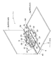
【図1】本発明の一実施形態を示す全体斜視図。
【図2】図1の分解斜視図。
【図3】図1の分解斜視図。
【図4】同開閉表紙部の内側の様子を示す全体斜視図。
【図5】本実施形態のファイル本体を示す背面図。
【図6】図5におけるX−X線断面図。
【図7】本実施形態の背カバー部材を示す背面側を示す図。
【図8】本実施形態の背カバー部材を示す前面側を示す図。
【図9】本実施形態の背カバー部材を示す側面図。
【図10】図7におけるY−Y線断面図。
【図11】図1におけるZ−Z線断面図による背表紙部を示す説明図。
【図12】図1におけるZ−Z線断面図による背表紙部を示す説明図。
【図13】本実施形態における変形例を示す説明図。
【図14】本実施形態における変形例を示す説明図。
【図15】本発明の別の実施形態における示す全体斜視図。
【図16】同実施形態の背面図。
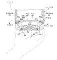
【図17】同実施形態における背表紙部の様子を示す部分断面図。
【符号の説明】
1、1’、A1・・・ファイル
2、2’、A2・・・ファイル本体
22、A22・・・係合部
2a、2b、2a’、2b’、A2a、A2b・・・開閉表紙部
2c、2c’・・・背部
2c2、2c2’・・・背部を貫通させた孔(貫通孔)
3、3‘、A3’・・・綴じ具
4、4’、A4・・・背カバー部材
4Ka、4Kb、4Ka’、4Kb’、A4K・・・開口
4W、4W’A4W・・・窓部
5a、5b、5a’、5b’、A5・・・凹部
6、6’A6・・・取手
7、A7・・・見出し片装着部
B、B’、AB・・・背表紙部
L、AL・・・見出し片[0001]
BACKGROUND OF THE INVENTION
The present invention relates to a file provided with a binding tool for binding or storing or using documents.
[0002]
[Prior art]
In recent years, a pair of front and back cover parts used in offices, a back cover part provided between the base ends of these open and close cover parts, and an inner surface of the back cover part or an inner surface near the base end part of the open and close cover part In a file having a binding tool, a plurality of handle members that can be gripped by hand are attached to the back cover part in parallel with the back cover part so as to protrude from the front surface (rear face) of the spine cover part. Products that can be taken out smoothly from the state and that are more convenient to carry are being developed.
[0003]
Furthermore, in a file configured by attaching such a handle member, the handle member is lifted from the surface of the spine cover portion, and the problem that the appearance of the spine cover portion is damaged is solved. It is also conceivable to form a handle housing portion that is recessed from the surface of the spine cover portion at the portion so that, when not in use, a handle member is housed in the handle housing portion so as not to protrude from the surface.
[0004]
[Problems to be solved by the invention]
However, in such a case, since the handle member is normally set at the center of the spine portion in consideration of the balance during use, the heading piece arranged on the spine portion is divided vertically. It will be. For a file whose back cover portion is to be placed on the front side on a bookshelf or the like, a heading piece indicating the contents of a document or the like bound to the binding tool is extremely important, and the heading piece is divided and small. It is inconvenient to become.
[0005]
On the other hand, it is considered that a concave part that allows a finger to be hooked is formed on the top and bottom of the spine part, and an area for mounting the heading piece is secured along the vertical direction. Even if the balance of gripping is poor and it is possible to pull it out from a bookshelf or the like, it is practically difficult to carry a file by gripping such a recess.
[0006]
Therefore, in order to solve the problems described above, a handle that does not impair the aesthetics of the file and that can be gripped in a balanced manner is provided, and a heading piece is provided in the center of the spine cover from the vicinity of the upper end to the vicinity of the lower end. Providing a new file with good usability that can secure the mounting area.
[0007]
[Means for Solving the Problems]
That is, the file of the present invention is provided on a pair of front and back open / close cover parts, a back cover part provided between the base ends of these open / close cover parts, and an inner surface of the back cover part or an inner surface near the base end part of the open / close cover part. And a binding tool for binding a body to be bound such as a document, wherein the opening includes at least a central portion in the vertical direction of the spine cover portion and is formed in the vicinity of at least one side end portion. A handle is provided in which a finger can be inserted and held in a concave portion that is continuous. The “center portion in the vertical direction” refers to the peripheral portion at the center in the vertical direction.
[0008]
With such a file, the center portion in the vertical direction on the spine cover side can be gripped by a handle provided in the file. In addition, since this handle uses a concave portion, it is possible to prevent the appearance of the file from being spoiled without being exposed outwardly from the spine portion like a case where a separate handle member is attached. Become. Furthermore, it is possible to secure an area for mounting a continuous heading piece from the vicinity of the upper end to the vicinity of the lower end without being interfered by the opening and the handle. Further, as long as the position for forming the opening is adjusted, the heading piece can be attached to the central portion in the width direction (left and right direction) of the spine cover portion so that it can be easily seen. That is, it is suitable for pulling out and carrying from the storage state, and has a handle that has a good weight balance when gripped and keeps the aesthetics of the file, and from the upper end to the lower end of the back cover. It becomes possible to provide a new file that has both easy-to-read headline pieces and improved usability.
[0009]
Further, as such a file, for example, an opening is formed so as to extend further up and down including the central portion in the vertical direction of the spine cover part, and the handle extends over the vertical part of the spine cover part. However, in order to secure the strength of the spine portion, it is preferable that the opening and the handle are provided only in the central portion in the vertical direction.
[0010]
In addition, in order to be able to handle both left and right fingers and to be able to grip in a stable state, openings should be formed in the vicinity of both side edges of the central portion in the vertical direction of the back cover. Thus, it is desirable to form the handle so that the fingers can be inserted from the left and right end portions.
[0011]
In addition, a file to which the present invention is applied includes a file body provided with the opening / closing cover portion and a back portion continuous between the base ends of the opening / closing cover portion, to which the binding tool is attached, and the back portion attached to cover the back portion. And a back cover member that constitutes the spine cover part, use a back cover member that has an effect of concealing a fixing tool or a rivet for attaching a binding tool. Thus, the handle can be provided in the central portion in the vertical direction on the back side of the spine cover portion without interfering with the binding tool attached to the central portion in the vertical direction of the inner surface of the spine cover portion. In particular, if the back cover member has a certain thickness dimension (front-rear width dimension), it is possible to use the thickness of the back cover member to form the recess and provide a handle.
[0012]
As a preferred specific mode of such a file, there is one in which a heading piece mounting portion is formed along the vertical direction at the center portion in the width direction of the spine portion, avoiding the opening. This is because it is easier to see the heading piece from either the left or right side.
[0013]
In addition, when the handle is provided on the back cover portion constituted by the back portion and the back cover member, the handle is formed integrally with the file body, Preferably, the opening is formed in the back cover member. If a handle is provided on the back cover member side, there is a possibility that the file body in the state in which documents etc. are bound to the engagement part between the back cover member and the file main body during work will be disengaged due to the load acting on the file main body. In such a case, since the file body is actually gripped, the engaging portion can be gripped in a stable state without loss.
[0014]
Further, when the handle is formed integrally with the file body, a window part opened on the back side is formed on the back cover member, and the file body is integrated with the window part through the window part. It is desirable that the molded handle is exposed through the window portion of the back cover member. In this way, the handle can be positioned on the back side by the thickness dimension of the wall portion of the back cover member that constitutes the window portion, that is, the thickness dimension of the wall portion is set to the concave portion into which the finger is inserted. It can be added to the thickness dimension. As a result, the thickness of the back cover member can be shortened, and the depth width of the file (length in the front-rear direction) can be shortened. When storing in a closed storage space such as a wagon drawer, This is particularly convenient when the open / close free end is positioned below. Then, if the handle is exposed through the window portion so as to be substantially flush with the peripheral portion of the window portion, even if the heading piece is attached across the window portion, Is easy to wear, and the heading piece is preferable in terms of appearance because it does not have an uneven shape.
[0015]
Further, in order to reduce the thickness of the back cover member as much as possible so that the thickness dimension of the concave portion can be increased, the thickness of the back portion penetrating the back portion so as to form a space continuously to the concave portion is penetrated. It is desirable to form a hole or a hole with a recessed back. And if the hole which penetrated such a back part or the hole which dented the back part shall be formed by the punching process at the time of shape | molding a handle, the convenience of manufacture can be aimed at now.
[0016]
In addition, in such a structure that the handle is exposed from the window part, it is desirable to attach the heading piece so as to conceal the handle exposed through the window part in order to maintain the beauty. And as a suitable specific mode for realizing such a concealment of the handle, the heading piece mounting portion according to
[0017]
In order to further improve the usability of a file having a handle in this way, it is desirable to provide a locking portion that selectively locks the open flat cover portion so that it cannot be opened. If this is the case, when holding the handle and storing it in a shelf, wagon, etc., it will be easy to store it in a predetermined place while keeping the opening / closing cover part unopened, and easy to carry Become. And as a specific aspect of such a locking part, it is formed in a part of the opening / closing cover part, and is engaged with a part of the binding tool by an operation from the outside, for example, in the closed state of the opening / closing cover part. What is configured is mentioned.
[0018]
DETAILED DESCRIPTION OF THE INVENTION
Hereinafter, an embodiment of the present invention will be described with reference to the drawings.
[0019]
The
[0020]
The file
[0021]
The open /
[0022]
The
[0023]
In addition, an attachment hole 2c1 for attaching a
[0024]
As shown in FIG. 4, the
[0025]
The
[0026]
Thus, in the present embodiment, the openings 4Ka and 4Kb are formed in the central portion in the vertical direction near the both end portions of the
[0027]
Specifically, first, the
[0028]
An
[0029]
The openings 4Ka and 4Kb are formed by setting the opening width so that a finger can be inserted from the side at the center in the vertical direction at the position straddling the both
[0030]
The
[0031]
Further, as shown in FIGS. 11 and 12, a through hole 2c2 is formed in the
[0032]
On the other hand, the heading
[0033]
Next, the procedure for assembling the
[0034]
The
[0035]
In addition, the
[0036]
Further, since the
[0037]
In addition, since the openings 4Ka and 4Kb are formed at both end portions, the
[0038]
As an effect peculiar to the present embodiment, since the
[0039]
Further, by gripping the
[0040]
Further, the gripping
[0041]
In addition, since the locking
[0042]
The present invention is not limited to the above embodiment.
[0043]
For example, as shown in FIGS. 13 and 14, a
In addition, the file A1 of the embodiment as shown in FIGS. In the figure, the configuration corresponding to the
[0044]
The file A1 is configured by fixing a back cover member A4 to a back portion A2c of a file body A2 having a configuration substantially similar to that of the
[0045]
Specifically, the handle A6 of this embodiment is so projected as to protrude from the back A2c of the file main body A2, as shown in the cross-sectional view of the state in which the heading piece AL and the heading piece cover ALC are not mounted in FIG. It is provided by integral molding with the file main body A2, and includes a gripping part A61 that is a part that comes into contact with fingers, and a support part A62 that supports the gripping part A61 so that the gripping part A61 is positioned rearward from the back surface A2ca by a predetermined distance. . And this handle A6 is made to expose on the back side from window part A4W formed in back cover member A4 similarly to the
[0046]
The heading mounting portion A7 has substantially the same configuration as the heading
[0047]
Further, the opening / closing cover portions A2a and A2b constituting the file main body A2 are formed with a locking tongue piece A22 which is a locking portion surrounded by a cut, and the opening and closing cover portions A2a and A2b are closed. In the closed state, it is configured to engage with a part of the corresponding binding tool A3 by operating it with a finger so that each of the open / close cover parts A2a and A2b can be locked so as not to be opened.
[0048]
Even with such a file A1, a handle A6 that can grip the center portion in the vertical direction of the spine portion AB when being pulled out from the stored state or carried, and that does not impair the appearance of the spine portion AB, It is possible to have an easy-to-see heading piece AL extending in the vertical direction. Furthermore, since the file A1 of this embodiment also has the handle A6 integrally formed with the file main body A2, the file A1 to which documents and the like are bound is directly held, and the back cover member A4 and the file main body The
[0049]
In addition, in this embodiment, you may make it further increase the thickness dimension of the said recessed part A5 by forming the hole penetrated in the back part A2c which comprises file main body A2, or the hollow hole. And if such a through-hole etc. are formed by the punching process for forming a handle like the said embodiment, the convenience of manufacture can be aimed at. In addition, the back cover member A4 in the illustrated example does not include a front wall portion, but includes a front wall portion, and an opening through which a handle is inserted to reach the window portion is formed in the front wall portion. It may be.
[0050]
In any of the above-described embodiments, an opening is formed in the back cover member, the inner space of the back cover member is formed as a concave portion continuous with the opening, and the back side of the back wall portion constituting the back cover member is gripped. The back cover member itself may be configured to function as a handle. If such a thing, the material for forming a handle is not required, but the convenience of manufacture can be aimed at and cost can also be reduced.
[0051]
In addition, the file is not provided with a back cover member but is composed of an opening / closing cover part and a back part, and a handle is provided by molding the back part to have a predetermined thickness dimension. It may be a thing.
[0052]
Further, the file may include a back member that integrally includes a back cover and an opening / closing cover part mounting portion that constitutes a part of the opening / closing cover part.
[0053]
Further, the binding tool attached to the file is not limited to the type used for the tube file as in the above embodiment, but may be the type used for the ring file.
[0054]
In addition, the specific configuration of each part is not limited to the above embodiment, and various modifications can be made without departing from the spirit of the present invention.
[0055]
【The invention's effect】
The present invention is implemented in the form as described above, and has the following effects.
[0056]
That is, according to the present invention, the center portion in the vertical direction on the spine cover side can be gripped by the handle provided in the file, and this handle uses a recess, so that a separate handle is used. It does not appear outward from the spine portion like a member is attached, and the appearance of the file is not impaired. Furthermore, it is possible to secure an area for mounting a continuous heading piece from the vicinity of the upper end to the vicinity of the lower end without being interfered by the opening and the handle. Further, as long as the position for forming the opening is adjusted, the heading piece can be attached to the central portion in the width direction (left-right direction) of the spine cover portion so that it is easier to see. In other words, a new file that is suitable for pulling out and carrying from the stored state and has a handle that keeps the aesthetic appearance of the file and an easy-to-see heading piece extending from the upper end to the lower end of the spine cover, and has improved usability. Can be provided.
[Brief description of the drawings]
FIG. 1 is an overall perspective view showing an embodiment of the present invention.
2 is an exploded perspective view of FIG. 1. FIG.
3 is an exploded perspective view of FIG. 1. FIG.
FIG. 4 is an overall perspective view showing the inside of the opening / closing cover part.
FIG. 5 is a rear view showing the file body of the embodiment.
6 is a cross-sectional view taken along line XX in FIG.
FIG. 7 is a view showing the back side of the back cover member of the present embodiment.
FIG. 8 is a diagram showing a front side showing a back cover member of the present embodiment.
FIG. 9 is a side view showing a back cover member of the present embodiment.
10 is a cross-sectional view taken along line YY in FIG.
11 is an explanatory diagram showing a spine portion according to a cross-sectional view taken along the line ZZ in FIG. 1. FIG.
12 is an explanatory view showing a spine portion according to a cross-sectional view taken along the line ZZ in FIG. 1. FIG.
FIG. 13 is an explanatory diagram showing a modification of the present embodiment.
FIG. 14 is an explanatory diagram showing a modification of the present embodiment.
FIG. 15 is an overall perspective view showing another embodiment of the present invention.
FIG. 16 is a rear view of the embodiment.
FIG. 17 is a partial cross-sectional view showing a situation of a spine portion in the same embodiment.
[Explanation of symbols]
1, 1 ', A1 ... file
2, 2 ', A2 ... File body
22, A22 ... engaging portion
2a, 2b, 2a ', 2b', A2a, A2b ... Open / close cover
2c, 2c '... back
2c2, 2c2 '... holes through the back (through holes)
3, 3 ', A3' ... binding tool
4, 4 ', A4 ... back cover member
4Ka, 4Kb, 4Ka ', 4Kb', A4K ... opening
4W, 4W'A4W ... Window
5a, 5b, 5a ', 5b', A5 ... concave portion
6, 6'A6 ... handle
7, A7 ... heading piece mounting part
B, B ', AB ... spine cover
L, AL ... Heading piece
Claims (11)
前記背表紙部の上下方向における中央部を少なくとも含んで少なくとも一方の側端部近傍に形成される開口を通じて当該開口に連続する凹部内に手指を差し入れて把持し得る取手を設けるとともに、
前記開閉表紙部と、この開閉表紙部の基端間に連続する背部とを備え前記綴じ具が取り付けられるファイル本体と、前記背部を覆うように取り付けられ当該背部と前記背表紙部を構成する背カバー部材とを備え、
前記取手が、前記ファイル本体と一体成形されたものであり、前記開口が、前記背カバー部材に形成されたものであることを特徴とするファイル。A pair of front and back opening and closing cover parts, a spine cover part provided between the base ends of these opening and closing cover parts, and a binding tool for binding a body to be bound such as documents,
While providing a handle that can be gripped by inserting a finger into a recess continuous with the opening through an opening formed in the vicinity of at least one side end including at least a central portion in the vertical direction of the spine portion,
A file main body provided with the opening / closing cover part and a back part continuous between the base ends of the opening / closing cover part, to which the binding tool is attached, and a spine that is attached to cover the back part and constitutes the back cover part A cover member,
The file is characterized in that the handle is formed integrally with the file body, and the opening is formed in the back cover member .
Priority Applications (2)
| Application Number | Priority Date | Filing Date | Title |
|---|---|---|---|
| JP2002201995A JP4201539B2 (en) | 2002-07-10 | 2002-07-10 | File |
| CN 02149063 CN1221404C (en) | 2002-07-10 | 2002-11-20 | File folder |
Applications Claiming Priority (1)
| Application Number | Priority Date | Filing Date | Title |
|---|---|---|---|
| JP2002201995A JP4201539B2 (en) | 2002-07-10 | 2002-07-10 | File |
Publications (2)
| Publication Number | Publication Date |
|---|---|
| JP2004042402A JP2004042402A (en) | 2004-02-12 |
| JP4201539B2 true JP4201539B2 (en) | 2008-12-24 |
Family
ID=29997142
Family Applications (1)
| Application Number | Title | Priority Date | Filing Date |
|---|---|---|---|
| JP2002201995A Expired - Lifetime JP4201539B2 (en) | 2002-07-10 | 2002-07-10 | File |
Country Status (2)
| Country | Link |
|---|---|
| JP (1) | JP4201539B2 (en) |
| CN (1) | CN1221404C (en) |
Families Citing this family (1)
| Publication number | Priority date | Publication date | Assignee | Title |
|---|---|---|---|---|
| JP6160050B2 (en) * | 2012-09-26 | 2017-07-12 | コクヨ株式会社 | File |
-
2002
- 2002-07-10 JP JP2002201995A patent/JP4201539B2/en not_active Expired - Lifetime
- 2002-11-20 CN CN 02149063 patent/CN1221404C/en not_active Expired - Lifetime
Also Published As
| Publication number | Publication date |
|---|---|
| CN1221404C (en) | 2005-10-05 |
| CN1467096A (en) | 2004-01-14 |
| JP2004042402A (en) | 2004-02-12 |
Similar Documents
| Publication | Publication Date | Title |
|---|---|---|
| JPS6239765Y2 (en) | ||
| USD453624S1 (en) | Tool box with compartment for a level | |
| JP2009502550A (en) | Activity center | |
| US4906057A (en) | Closed portable card file | |
| JP4201539B2 (en) | File | |
| US3198299A (en) | Luggage cases | |
| US20030085141A1 (en) | Compartmentalized tool box | |
| US20050109790A1 (en) | Window tabs storage case | |
| US20090158516A1 (en) | Carrying stool | |
| JP4769960B2 (en) | Key holding tool and key management case | |
| USD523839S1 (en) | Traveller's FM-scanner alarm clock with flashlight | |
| JP2661433B2 (en) | wagon | |
| JPH068809Y2 (en) | Compact container | |
| CN215455963U (en) | Glasses case | |
| JPH0423805Y2 (en) | ||
| JPH0722162Y2 (en) | Compact container | |
| JP6356650B2 (en) | Finding holder | |
| JP2545024Y2 (en) | Hook structure of container with lid | |
| KR930006143Y1 (en) | Sectional bag | |
| JPH088669Y2 (en) | Handle with name tag | |
| KR200266778Y1 (en) | A case for manicure and nail clipper set | |
| JP3057703U (en) | File cover | |
| JPS6214968Y2 (en) | ||
| JP3700023B2 (en) | Lid locking mechanism | |
| JP2017141634A (en) | Folding door |
Legal Events
| Date | Code | Title | Description |
|---|---|---|---|
| A621 | Written request for application examination |
Free format text: JAPANESE INTERMEDIATE CODE: A621 Effective date: 20050523 |
|
| A977 | Report on retrieval |
Free format text: JAPANESE INTERMEDIATE CODE: A971007 Effective date: 20080328 |
|
| A131 | Notification of reasons for refusal |
Free format text: JAPANESE INTERMEDIATE CODE: A131 Effective date: 20080422 |
|
| A521 | Request for written amendment filed |
Free format text: JAPANESE INTERMEDIATE CODE: A523 Effective date: 20080617 |
|
| A131 | Notification of reasons for refusal |
Free format text: JAPANESE INTERMEDIATE CODE: A131 Effective date: 20080715 |
|
| A521 | Request for written amendment filed |
Free format text: JAPANESE INTERMEDIATE CODE: A523 Effective date: 20080909 |
|
| TRDD | Decision of grant or rejection written | ||
| A01 | Written decision to grant a patent or to grant a registration (utility model) |
Free format text: JAPANESE INTERMEDIATE CODE: A01 Effective date: 20081007 |
|
| A01 | Written decision to grant a patent or to grant a registration (utility model) |
Free format text: JAPANESE INTERMEDIATE CODE: A01 |
|
| A61 | First payment of annual fees (during grant procedure) |
Free format text: JAPANESE INTERMEDIATE CODE: A61 Effective date: 20081007 |
|
| R150 | Certificate of patent or registration of utility model |
Free format text: JAPANESE INTERMEDIATE CODE: R150 Ref document number: 4201539 Country of ref document: JP Free format text: JAPANESE INTERMEDIATE CODE: R150 |
|
| FPAY | Renewal fee payment (event date is renewal date of database) |
Free format text: PAYMENT UNTIL: 20111017 Year of fee payment: 3 |
|
| FPAY | Renewal fee payment (event date is renewal date of database) |
Free format text: PAYMENT UNTIL: 20121017 Year of fee payment: 4 |
|
| FPAY | Renewal fee payment (event date is renewal date of database) |
Free format text: PAYMENT UNTIL: 20131017 Year of fee payment: 5 |
|
| R250 | Receipt of annual fees |
Free format text: JAPANESE INTERMEDIATE CODE: R250 |
|
| EXPY | Cancellation because of completion of term |