JP4201068B2 - Portable wireless device - Google Patents
Portable wireless device Download PDFInfo
- Publication number
- JP4201068B2 JP4201068B2 JP32294399A JP32294399A JP4201068B2 JP 4201068 B2 JP4201068 B2 JP 4201068B2 JP 32294399 A JP32294399 A JP 32294399A JP 32294399 A JP32294399 A JP 32294399A JP 4201068 B2 JP4201068 B2 JP 4201068B2
- Authority
- JP
- Japan
- Prior art keywords
- fitting
- convex portion
- concave hole
- cover
- key sheet
- Prior art date
- Legal status (The legal status is an assumption and is not a legal conclusion. Google has not performed a legal analysis and makes no representation as to the accuracy of the status listed.)
- Expired - Fee Related
Links
Images


Classifications
-
- H—ELECTRICITY
- H04—ELECTRIC COMMUNICATION TECHNIQUE
- H04M—TELEPHONIC COMMUNICATION
- H04M1/00—Substation equipment, e.g. for use by subscribers
- H04M1/02—Constructional features of telephone sets
- H04M1/23—Construction or mounting of dials or of equivalent devices; Means for facilitating the use thereof
-
- H—ELECTRICITY
- H04—ELECTRIC COMMUNICATION TECHNIQUE
- H04M—TELEPHONIC COMMUNICATION
- H04M1/00—Substation equipment, e.g. for use by subscribers
- H04M1/02—Constructional features of telephone sets
- H04M1/0202—Portable telephone sets, e.g. cordless phones, mobile phones or bar type handsets
Description
【0001】
【発明の属する技術分野】
本発明は、携帯無線装置に関し、特にキーシートを圧入嵌合してカバーに取り付ける場合に取付け易く、取付けた後は外れにくくするよう構成したものである。
【0002】
【従来の技術】
現在の携帯無線装置では、薄型化・小型化と大量生産によるコストダウン化が生産の上での使命となっており、各メーカは日夜腐心しているところである。そのため内蔵部品であるキーシートも薄型化・小型化が要求されており、薄型化・小型化かつ大量生産化されても取付け易く、外れにくくすることが求められている。
【0003】
しかし従来、携帯無線装置においてキーシートをカバーに取付ける場合、大量生産を優先するあまり、図7に示すように、取付けも、取り外しも簡単になってしまうような設計となるか、あるいは図8のように取付易いが実装部品等の配置関係からその設置場所が限定されてしまう設計となるか、または大量生産性を意識せずに図9に示されるような実装部品等の配置関係に影響されないが、取付寸法を厳密化してしまうために外れにくいが取付けにくい設計となっていた。
【0004】
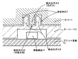
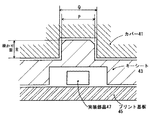
すなわち、図7から図9はカバーに設けた嵌合凸部と、キーシートに設けた嵌合凹部の断面図を示すものである。なお、図面では説明のために嵌合凸部と嵌合凹部との間に隙間があるように示しているが、図7においてはキーシート23に設けた嵌合凹部としての嵌合穴の穴径Gがカバー21に設けた嵌合凸部の外径Fよりも小さくなるように設計されており、この設計の下で嵌合凸部が嵌合凹部に圧入嵌合してキーシート23をカバー21に取付けていた。そのため、簡単に取付けできるが、簡単に外れてしまうという問題があった。なお、図7においては掛かり量Hは薄型化のためにあまりとれない構造となっている。
【0005】
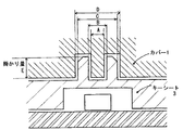
また、図8に示したものは、カバー31に設けた嵌合凸部の周囲にも嵌合凹部を設け、またキーシート33に設けた嵌合凹部の周囲にも嵌合凸部を設けておき、カバー31に設けた嵌合凸部の外径Jよりも小さくなるようにキーシート33に設けた嵌合凹部の内径Kを設計し、さらにカバー31に設けた嵌合凸部の周囲に設けた嵌合凹部の内径Mがキーシート33に設けた嵌合凹部の周囲に設けた嵌合凸部の外径Lよりも大きくなるように設計してある。この図8の例は取付け易く、掛かり量Nを自由に取れるが、掛かり量Nを確保するために嵌合凸部と嵌合凹部を設ける場所が実装部品等の配置関係に影響されて設置場所が限定されるという問題点があった。また、薄型化の影響を受けざるを得ない構造となっている。
【0006】
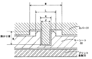
また、図9に示したものは、実装部品47がプリント基板45上にあるときに、実装部品47より大きい逃げ用の凹部をキーシート43に設けて、実装部品の配置関係に影響されないようにしたもので、キーシート43に設けた嵌合凸部の外径Pがカバー41に設けた嵌合凹部の内径Qが接近した値となるように設計して、この設計の下で圧入嵌合してキーシート43をカバー41に取付けるので、取付けにくく取り外しにくくなってしまうという問題点があった。なお、図9においては掛かり量Rは自由に取れるが薄型化の影響を受けざるを得ない構造となっている。
【0007】
【発明が解決しようとする課題】
本発明は、上記従来の問題を解決するもので、キーシートを圧入嵌合してカバーに取り付ける場合に取付け易く、取付けた後は外れにくくするように構成したを携帯無線装置提供することを目的とする。
【0008】
【課題を解決するための手段】
本発明の請求項1に記載の発明は、
キートップを有するキーシートと、前記キートップが挿入されるキートップ孔を有するカバーとを合体させて、キー操作部を構成する携帯無線装置において、前記カバーまたは前記キーシートの一方には、嵌合用凹穴と、この凹穴の中にこの凹穴の深さとほぼ同じ高さの嵌合用凸部を備えるようにし、他方には嵌合用凸部と、この凸部の中心にこの凸部の高さとほぼ同じ深さの嵌合用凹穴を備えるようにして、前記カバーに設けたキートップ孔に前記キートップを嵌入するときに前記嵌合用凹穴と嵌合用凸部とを圧入嵌合することにより取付けたことを特徴とする携帯無線装置としたものである。
【0009】
この構成により、キーシートをカバーと合体させるに際しては、取付け易く、取付けた後は外れにくくすることができる。
【0010】
また、請求項2に記載の発明は、前記嵌合用凹穴の中央に設けた嵌合用凸部と前記嵌合用凸部の中央に設けた嵌合用凹穴の嵌合関係は、締まりばめとしたことを特徴とする請求項1に記載の携帯無線装置としたものである。また、請求項3に記載の発明は、前記嵌合用凹穴の中央に設けた嵌合用凸部と前記嵌合用凸部の中央に設けた嵌合用凹穴の嵌合関係は、締まりばめとし、前記中央に設けられた嵌合用凹部と嵌合用凸部以外の嵌合関係は、すきまばめまたは中間ばめとしたことを特徴とする請求項1に記載の携帯無線装置としたものである。
【0011】
この構成により、請求項2と請求項3に記載の発明では、締まりばめにより前記中央に設けられた嵌合用凹穴が押し広げられ、その外側にある前記中央に設けられた嵌合用凹穴と嵌合用凸部以外の嵌合状態が締まりばめとなることから、キーシートをカバーと合体させるに際しては、取付け易く、取付けた後は外れにくくすることができる。
【0012】
本発明の請求項4に記載の発明は、キートップを有するキーシートと、前記キートップが挿入されるキートップ孔を有するカバーとを合体させて、キー操作部を構成する携帯無線装置において、前記カバーには、嵌合用凹穴と、この凹穴の中にこの凹穴の深さとほぼ同じ高さの嵌合用凸部を備えるようにし、前記キーシートには、嵌合用凸部と、この凸部の中心にこの凸部の高さとほぼ同じ深さの嵌合用凹穴を備えるようにして、前記カバーに設けたキートップ孔に前記キートップを嵌入するときに前記キーシートを圧入嵌合することにより取付けたことを特徴とする携帯無線装置としたものである。
【0013】
この構成により、取付け易く、取付けた後は外れにくくすることができる。
【0014】
また、請求項5に記載の発明は、前記嵌合用凹穴の中に設けられた前記嵌合用凸部は、前記カバーに立設したボスであることを特徴とする請求項4に記載の携帯無線装置としたものである。
【0015】
この構成により、構造が簡単であるが取付け易く、取付けた後は外れにくくすることができる。
【0016】
また、請求項6に記載の発明は、前記ボスの形状を円筒形としたことを特徴とする請求項5に記載の携帯無線装置としたものである。
【0017】
この構成により、構造が簡単であるが取付け易く、取付けた後は外れにくくすることができる。
【0018】
また、請求項7に記載の発明は、前記カバーに設けられた凹穴の中に嵌合用凸部を有する前記嵌合用凹穴は、前記カバーの縦方向の中心線に線対称に設けられ、且つ上端に設けられた前記嵌合用凹穴は、前記カバーの左右端部にあり、前記下端に設けられた前記嵌合用凹穴は、前記カバーの縦方向の中心線の近傍にあることを特徴とする請求項4に記載の携帯無線装置としたものである。
【0019】
この構成により、小型化で取付け位置が少ない箇所しか取れないにも拘わらず取付け易く、取付けた後は外れにくくすることができる。
【0020】
また、請求項8に記載の発明は、前記上端に設けられた前記嵌合用凹穴は、前記下端に設けられた前記嵌合用凹穴よりも深くなるように設定されていることを特徴とする請求項7に記載の携帯無線装置としたものである。
【0021】
この構成により、取付け易く、取付けた後は外れにくくすることができる。
【0022】
また、請求項9に記載の発明は、前記キーシートに設けられた中心に嵌合用凹穴を有する前記嵌合用凸部は、前記キーシートと同一材料で形成される中空円筒状のものであることを特徴とする請求項4に記載の携帯無線装置としたものである。
【0023】
この構成により、構造が簡単であるが取付け易く、取付けた後は外れにくくすることができる。
【0024】
また、請求項10に記載の発明は、前記キーシートはシリコンゴムであることを特徴とする請求項9に記載の携帯無線装置としたものである。
【0025】
この構成により、構造が簡単であるが取付け易く、取付けた後は外れにくくすることができる。
【0026】
また、請求項11に記載の発明は、前記キーシートに設けられた中心に嵌合用凹穴を有する前記嵌合用凸部は、前記キーシートの縦方向の中心線に線対称に設けられ、且つ上端に設けられた前記嵌合用凸部は、前記キーシートの左右端部にあり、前記下端に設けられた前記嵌合用凸部は、前記キーシートの縦方向の中心線の近傍にあることを特徴とする請求項4に記載の携帯無線装置としたものである。
【0027】
この構成により、小型化で取付け位置が少ない箇所しか取れないにも拘わらず取付け易く、取付けた後は外れにくくすることができる。
【0028】
また、請求項12に記載の発明は、前記上端に設けられた前記嵌合用凸部は、前記下端に設けられた前記嵌合用凸部よりも高くなるように設定されていることを特徴とする請求項11に記載の携帯無線装置としたものである。
【0029】
この構成により、構造が簡単であるが取付け易く、取付けた後は外れにくくすることができる。
【0030】
【発明の実施の形態】
以下、本発明の実施の形態について、図1から図6を用いて説明する。
【0031】
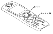
図1は本発明の実施の形態における携帯無線装置に係るカバー1とキーシート3の分解斜視図である。図2は本発明の実施の形態における携帯無線装置に係るカバー1にキーシート3を取付けた後の斜視図である。また、図3は本発明の実施の形態における携帯無線装置に係るカバー1の裏面図である。
【0032】
図1において携帯無線装置のカバー1には、キーシート3に装着されたキートップ4が挿入されるキートップ孔2が設けられている。一方、キーシート3にはキートップ4が設けられ、さらにキーシート3がカバー1に圧入嵌合される位置に第1の取付部5および第2の取付部6が設けられている。
【0033】
そして、図2に示すようにキーシート3をカバー1に取付ける。その場合、図3に示すように、キーシート3側に設けられている第1の取付部5および第2の取付部6に対応してカバー1側にも第1の取付部5'および第2の取付部6'が設けられている。
【0034】
図4〜図6は、キーシート3側に設けられている取付部の構成と、カバー1側に設けられている取付部の構成を示すものである。
【0035】
図4においてカバー1側に設けられている取付部5'または6'には、嵌合凹穴7に嵌合凸ボス(中凸ボス)8が設けられている。一方、キーシート3側に設けられている取付部5または6には、嵌合凸ボス9に嵌合凹穴(中抜き凹)10が設けられている。なお図4の例においては、キーシート3に実装部品11をプリント基板12との間に設けることができるようにされている。
【0036】
図5は、図4における各部の寸法関係を説明するための断面図であり、図面では説明のために嵌合凸ボス9と嵌合凹穴10との間に隙間があるように示しているが、嵌合凸ボス(中凸ボス)8の外径Aよりも嵌合凹穴(中抜き凹)10の内径Bの方が少しだけ小さくなるように設定されている。また、嵌合凸ボス9の外径Cよりも嵌合凹穴7の内径Dの方が少しだけ大きくなるように設定されている。なお嵌合の掛かり量Eは相互の挿入量によって決定される。
【0037】
図6は、図5における実際の嵌合の様子を説明する断面図である。図6において図5で説明したA寸法の嵌合凸ボス8をB寸法の嵌合凹穴10に圧入することで、C寸法の嵌合凸ボス9がキーシート3がゴムで構成されていることにより外に膨らむ。このためクリアランスを設定していた分がなくなり、C寸法が嵌合凹穴の寸法である略D寸法に等しくなり、C寸法とD寸法の嵌合が発生する。このように、A寸法とB寸法、およびC寸法とD寸法のダブルの嵌合が起こることによって取付け易く、外れにくい取付けが実現される。
【0038】
なお、上記実施の形態の説明では、カバーに嵌合用凹穴とこの凹穴の中に嵌合用凸部を備えるようにし、キーシートに嵌合用凸部とこの凸部の中心に嵌合用凹穴を備えた形態を例示したが、これとは逆に、キーシートに嵌合用凹穴とこの凹穴の中に嵌合用凸部を備えるようにし、カバーに嵌合用凸部とこの凸部の中心に嵌合用凹穴を備えた形態としても良い。
【0039】
また、上記の本発明の実施の形態では、嵌合用凹穴の中に設けられた嵌合用凸部はカバーに立設した円筒形のボスに形成し、カバーに縦方向の中心線に線対称に設けることによって取付け易く外れにくい構成にしている。また、中心線に対する凹穴の距離を上端と下端で異ならせて外れにくくするという配置にしている。なた凹穴の深さについても上端と下端で深さに差をつけて外れにくくしている。材質についてもキーシートをシリコンゴムとし、嵌合用凹穴を有する嵌合用凸部をキーシートと同一部材としている。
【0040】
【発明の効果】
以上のように本発明の請求項1に記載の発明は、キートップを有するキーシートと、前記キートップが挿入されるキートップ孔を有するカバーとを合体させて、キー操作部を構成する携帯無線装置において、前記カバーまたは前記キーシートの一方には、嵌合用凹穴と、この凹穴の中にこの凹穴の深さとほぼ同じ高さの嵌合用凸部を備えるようにし、他方には嵌合用凸部と、この凸部の中心にこの凸部の高さとほぼ同じ深さの嵌合用凹穴を備えるようにして、前記カバーに設けたキートップ孔に前記キートップを嵌入するときに前記嵌合用凹穴と嵌合用凸部とを圧入嵌合することにより取付けたことを特徴とする携帯無線装置としたものであり、これにより、キーシートをカバーと合体させるに際しては、取付け易く、取付けた後は外れにくくすることができるという利点がある。
【0041】
また、請求項2に記載の発明は、前記嵌合用凹穴の中央に設けた嵌合用凸部と前記嵌合用凸部の中央に設けた嵌合用凹穴の嵌合関係は、締まりばめとしたことを特徴とする請求項1に記載の携帯無線装置としたものである。また、請求項3に記載の発明は、前記嵌合用凹穴の中央に設けた嵌合用凸部と前記嵌合用凸部の中央に設けた嵌合用凹穴の嵌合関係は、締まりばめとし、前記中央に設けられた嵌合用凹部と嵌合用凸部以外の嵌合関係は、すきまばめまたは中間ばめとしたことを特徴とする請求項1に記載の携帯無線装置としたものである。この構成により、請求項2と請求項3に記載の発明では、締まりばめにより前記中央に設けられた嵌合用凹穴が押し広げられ、その外側にある前記中央に設けられた嵌合用凹穴と嵌合用凸部以外の嵌合状態が締まりばめとなることから、キーシートをカバーと合体させるに際しては、取付け易く、取付けた後は外れにくくすることができるという利点がある。
【0042】
本発明の請求項4に記載の発明は、キートップを有するキーシートと、前記キートップが挿入されるキートップ孔を有するカバーとを合体させて、キー操作部を構成する携帯無線装置において、前記カバーには、嵌合用凹穴と、この凹穴の中にこの凹穴の深さとほぼ同じ高さの嵌合用凸部を備えるようにし、前記キーシートには、嵌合用凸部と、この凸部の中心にこの凸部の高さとほぼ同じ深さの嵌合用凹穴を備えるようにして、前記カバーに設けたキートップ孔に前記キートップを嵌入するときに前記キーシートを圧入嵌合することにより取付けたことを特徴とする携帯無線装置としたものであり、これにより、取付け易く、取付けた後は外れにくくすることができるという利点がある。
【0043】
また、請求項5に記載の発明は、前記嵌合用凹穴の中に設けられた前記嵌合用凸部は、前記カバーに立設したボスであることを特徴とする請求項4に記載の携帯無線装置としたものであり、これにより、構造が簡単であるが取付け易く、取付けた後は外れにくくすることができるという利点がある。
【0044】
また、請求項6に記載の発明は、前記ボスの形状を円筒形としたことを特徴とする請求項5に記載の携帯無線装置としたものであり、これにより、構造が簡単であるが取付け易く、取付けた後は外れにくくすることができるという利点がある。
【0045】
また、請求項7に記載の発明は、前記カバーに設けられた凹穴の中に嵌合用凸部を有する前記嵌合用凹穴は、前記カバーの縦方向の中心線に線対称に設けられ、且つ上端に設けられた前記嵌合用凹穴は、前記カバーの左右端部にあり、前記下端に設けられた前記嵌合用凹穴は、前記カバーの縦方向の中心線の近傍にあることを特徴とする請求項4に記載の携帯無線装置としたものであり、これにより、小型化で取付け位置が少ない箇所しか取れないにも拘わらず取付け易く、取付けた後は外れにくくすることができるという利点がある。
【0046】
また、請求項8に記載の発明は、前記上端に設けられた前記嵌合用凹穴は、前記下端に設けられた前記嵌合用凹穴よりも深くなるように設定されていることを特徴とする請求項7に記載の携帯無線装置としたものであり、これにより、取付け易く、取付けた後は外れにくくすることができるという利点がある。
【0047】
また、請求項9に記載の発明は、前記キーシートに設けられた中心に嵌合用凹穴を有する前記嵌合用凸部は、前記キーシートと同一材料で形成される中空円筒状のものであることを特徴とする請求項4に記載の携帯無線装置としたものであり、これにより、構造が簡単であるが取付け易く、取付けた後は外れにくくすることができる。
【0048】
また、請求項10に記載の発明は、前記キーシートはシリコンゴムであることを特徴とする請求項9に記載の携帯無線装置としたものであり、これにより、構造が簡単であるが取付け易く、取付けた後は外れにくくすることができるという利点がある。
【0049】
また、請求項11に記載の発明は、前記キーシートに設けられた中心に嵌合用凹穴を有する前記嵌合用凸部は、前記キーシートの縦方向の中心線に線対称に設けられ、且つ上端に設けられた前記嵌合用凸部は、前記キーシートの左右端部にあり、前記下端に設けられた前記嵌合用凸部は、前記キーシートの縦方向の中心線の近傍にあることを特徴とする請求項4に記載の携帯無線装置としたものであり、これにより、小型化で取付け位置が少ない箇所しか取れないにも拘わらず取付け易く、取付けた後は外れにくくすることができるという利点がある。
【0050】
また、請求項12に記載の発明は、前記上端に設けられた前記嵌合用凸部は、前記下端に設けられた前記嵌合用凸部よりも高くなるように設定されていることを特徴とする請求項11に記載の携帯無線装置としたものであり、これにより、構造が簡単であるが取付け易く、取付けた後は外れにくくすることができるという利点がある。
【図面の簡単な説明】
【図1】本発明の実施の形態における携帯無線装置に係るカバーとキーシートの分解斜視図、
【図2】本発明の実施の形態における携帯無線装置に係るカバーにキーシートを取付けた後の斜視図、
【図3】本発明の実施の形態における携帯無線装置に係るカバーの裏面図、
【図4】キーシート側に設けられている取付部の構成と、カバー側に設けられている取付部の構成を示す断面図、
【図5】図4における各部の寸法関係を説明するための断面図、
【図6】図5における実際の嵌合の様子を説明する断面図、
【図7】第1の従来例におけるキーシート側に設けられている取付部の構成と、カバー側に設けられている取付部の構成を示す断面図、
【図8】第2の従来例におけるキーシート側に設けられている取付部の構成と、カバー側に設けられている取付部の構成を示す断面図、
【図9】第3の従来例におけるキーシート側に設けられている取付部の構成と、カバー側に設けられている取付部の構成を示す断面図である。
【符号の説明】
1、21、31、41 カバー
2 キートップ孔
3、23、33、43 キーシート
4 キートップ
5、5' 第1の取付部
6、6' 第2の取付部
7 嵌合凹穴(カバー側)
8 嵌合凸ボス(カバー側)
9 嵌合凸ボス(キーシート側)
10 嵌合凹穴(キーシート側)
11、47 実装部品
12、25、35、45 プリント基板[0001]
BACKGROUND OF THE INVENTION
The present invention relates to a portable wireless device, and is particularly configured to be easily attached when a key sheet is press-fitted and attached to a cover, and is difficult to come off after being attached.
[0002]
[Prior art]
In current portable wireless devices, the mission of production is to reduce the thickness and size, and to reduce the cost by mass production, and manufacturers are struggling day and night. For this reason, the key sheet, which is a built-in component, is also required to be thin and small, and it is required to be easy to attach and hard to come off even if it is thin, small, and mass-produced.
[0003]
However, conventionally, when attaching a key sheet to a cover in a portable wireless device, as shown in FIG. 7, it is designed to be easy to attach and remove as shown in FIG. It is easy to install, but the installation location is limited due to the placement relationship of the mounted components, or is not affected by the placement relationship of the mounted components as shown in FIG. 9 without being conscious of mass productivity. However, since the mounting dimensions are tightened, the design is difficult to come off but difficult to mount.
[0004]
That is, FIGS. 7 to 9 show sectional views of the fitting convex portion provided on the cover and the fitting concave portion provided on the key sheet. In the drawing, for the sake of explanation, there is shown a gap between the fitting convex part and the fitting concave part. However, in FIG. 7, the hole of the fitting hole as the fitting concave part provided in the key sheet 23 is shown. The diameter G is designed to be smaller than the outer diameter F of the fitting convex portion provided on the cover 21. Under this design, the fitting convex portion is press-fitted into the fitting concave portion so that the key sheet 23 is attached. It was attached to the cover 21. Therefore, although it can be easily attached, there is a problem that it is easily detached. In addition, in FIG. 7, the amount of application H has a structure that cannot be taken much for thinning.
[0005]
In addition, the one shown in FIG. 8 is provided with a fitting concave portion around the fitting convex portion provided on the cover 31, and also provided with a fitting convex portion around the fitting concave portion provided on the
[0006]
Further, in the case shown in FIG. 9, when the mounting component 47 is on the printed circuit board 45, a recess for escaping larger than the mounting component 47 is provided in the
[0007]
[Problems to be solved by the invention]
The present invention solves the above-described conventional problems, and an object of the present invention is to provide a portable radio device configured to be easy to attach when a key sheet is press-fitted and attached to a cover, and to be difficult to come off after being attached. And
[0008]
[Means for Solving the Problems]
The invention described in claim 1 of the present invention
In a portable wireless device that forms a key operation unit by combining a key sheet having a key top and a cover having a key top hole into which the key top is inserted, one of the cover and the key sheet is fitted to the cover. A fitting concave hole, and a fitting convex portion having a height substantially the same as the depth of the concave hole is provided in the concave hole, and the fitting convex portion is provided on the other side, and the convex portion is formed at the center of the convex portion. A fitting concave hole having a depth substantially the same as the height is provided, and the fitting concave hole and the fitting convex portion are press-fitted and fitted when the key top is fitted into the key top hole provided in the cover. Thus, the portable wireless device is characterized in that it is attached.
[0009]
With this configuration, when the key sheet is united with the cover, it can be easily attached, and can be made difficult to come off after being attached.
[0010]
In the invention according to claim 2, the fitting relationship between the fitting convex portion provided at the center of the fitting concave hole and the fitting concave hole provided at the center of the fitting convex portion is an interference fit. The portable wireless device according to claim 1, wherein the portable wireless device is provided. According to a third aspect of the present invention, the fitting relationship between the fitting convex portion provided at the center of the fitting concave hole and the fitting concave hole provided at the center of the fitting convex portion is an interference fit. 2. The portable wireless device according to claim 1, wherein the fitting relationship other than the fitting concave portion and the fitting convex portion provided in the center is a clearance fit or an intermediate fit. .
[0011]
With this configuration, in the inventions according to claim 2 and
[0012]
According to a fourth aspect of the present invention, there is provided a portable wireless device that forms a key operation unit by combining a key sheet having a key top and a cover having a key top hole into which the key top is inserted. The cover is provided with a fitting concave hole, and a fitting convex portion having a height substantially the same as the depth of the concave hole is provided in the concave hole , and the key sheet has a fitting convex portion, The key sheet is press-fitted when the key top is inserted into the key top hole provided in the cover so that the center of the convex part has a fitting concave hole having a depth substantially equal to the height of the convex part. In this way, the portable wireless device is attached.
[0013]
With this configuration, it is easy to install and can be made difficult to come off after being installed.
[0014]
According to a fifth aspect of the present invention, the fitting convex portion provided in the concave fitting hole is a boss standing on the cover. This is a wireless device.
[0015]
With this configuration, the structure is simple, but it is easy to attach, and it is difficult to come off after being attached.
[0016]
The invention according to claim 6 is the portable wireless device according to claim 5, wherein the boss has a cylindrical shape.
[0017]
With this configuration, the structure is simple, but it is easy to attach, and it is difficult to come off after being attached.
[0018]
Further, in the invention according to claim 7, the fitting concave hole having the fitting convex portion in the concave hole provided in the cover is provided symmetrically with respect to the longitudinal center line of the cover, The fitting concave hole provided at the upper end is at the left and right ends of the cover, and the fitting concave hole provided at the lower end is in the vicinity of the vertical center line of the cover. The portable wireless device according to claim 4 is provided.
[0019]
According to this configuration, it is easy to mount despite the fact that only a portion with a small mounting position and a small mounting position can be taken, and it is possible to make it difficult to come off after mounting.
[0020]
The invention according to claim 8 is characterized in that the fitting recessed hole provided at the upper end is set deeper than the fitting recessed hole provided at the lower end. The portable wireless device according to claim 7 is provided.
[0021]
With this configuration, it is easy to install and can be made difficult to come off after being installed.
[0022]
According to a ninth aspect of the present invention, the fitting convex portion having a fitting concave hole in the center provided in the key sheet is a hollow cylindrical shape formed of the same material as the key sheet. The portable wireless device according to claim 4 is provided.
[0023]
With this configuration, the structure is simple, but it is easy to attach, and it is difficult to come off after being attached.
[0024]
The invention according to claim 10 is the portable wireless device according to claim 9, wherein the key sheet is made of silicon rubber.
[0025]
With this configuration, the structure is simple, but it is easy to attach, and it is difficult to come off after being attached.
[0026]
The invention according to claim 11 is characterized in that the fitting convex portion having a fitting concave hole at the center provided on the key sheet is provided symmetrically with respect to a vertical center line of the key sheet, and The fitting convex portion provided at the upper end is at the left and right end portions of the key sheet, and the fitting convex portion provided at the lower end is in the vicinity of the vertical center line of the key sheet. The portable wireless device according to claim 4 is characterized.
[0027]
According to this configuration, it is easy to mount despite the fact that only a portion with a small mounting position and a small mounting position can be taken, and it is possible to make it difficult to come off after mounting.
[0028]
The invention according to
[0029]
With this configuration, the structure is simple, but it is easy to attach, and it is difficult to come off after being attached.
[0030]
DETAILED DESCRIPTION OF THE INVENTION
Hereinafter, embodiments of the present invention will be described with reference to FIGS.
[0031]
FIG. 1 is an exploded perspective view of a cover 1 and a
[0032]
In FIG. 1, a cover 1 of a portable wireless device is provided with a key top hole 2 into which a key top 4 attached to a
[0033]
Then, the
[0034]
4 to 6 show the configuration of the mounting portion provided on the
[0035]
In FIG. 4, the fitting portion 5 ′ or 6 ′ provided on the cover 1 side is provided with a fitting convex boss (medium convex boss) 8 in the fitting concave hole 7. On the other hand, in the mounting portion 5 or 6 provided on the
[0036]
FIG. 5 is a cross-sectional view for explaining the dimensional relationship of each part in FIG. 4, and in the drawing, there is shown a gap between the fitting convex boss 9 and the fitting concave hole 10 for explanation. However, the inner diameter B of the fitting concave hole (centering concave) 10 is set to be slightly smaller than the outer diameter A of the fitting convex boss (medium convex boss) 8. Further, the inner diameter D of the fitting concave hole 7 is set to be slightly larger than the outer diameter C of the fitting convex boss 9. The engagement amount E is determined by the mutual insertion amount.
[0037]
FIG. 6 is a cross-sectional view for explaining an actual fitting state in FIG. In FIG. 6, the fitting convex boss 8 having the A dimension described in FIG. 5 is press-fitted into the fitting concave hole 10 having the B dimension, so that the fitting convex boss 9 having the C dimension has the
[0038]
In the description of the above embodiment, the cover has a fitting concave hole and a fitting convex portion in the concave hole, and the key sheet has a fitting convex portion and a fitting concave hole at the center of the convex portion. On the contrary, the key sheet is provided with a fitting concave hole and a fitting convex portion in the concave hole, and the cover has a fitting convex portion and the center of the convex portion. It is good also as a form provided with the concave hole for fitting.
[0039]
Further, in the embodiment of the present invention described above, the fitting convex portion provided in the fitting concave hole is formed on the cylindrical boss standing on the cover, and the cover is symmetrical with respect to the vertical center line. So that it is easy to mount and hard to come off. Further, the distance of the concave hole with respect to the center line is made different at the upper end and the lower end to make it difficult to come off. The depth of the pit is also made difficult to remove by making a difference in depth between the upper and lower ends. Regarding the material, the key sheet is made of silicon rubber, and the fitting convex part having the fitting concave hole is made the same member as the key sheet.
[0040]
【The invention's effect】
As described above, according to the first aspect of the present invention, the key sheet having the key top and the cover having the key top hole into which the key top is inserted are combined to form a key operation unit. In the wireless device, one of the cover or the key sheet is provided with a fitting concave hole, and a fitting convex portion having a height substantially equal to the depth of the concave hole is provided in the concave hole, a fitting protrusion, the center of the convex portion so as to comprise a fitting recess hole of approximately the same depth as the height of the convex portion, when fitted the key top to the key top hole provided in the cover It is a portable wireless device characterized by being fitted by press-fitting the fitting concave hole and the fitting convex portion, and thereby, when combining the key sheet with the cover, it is easy to attach, It is hard to come off after installation There is an advantage that can be.
[0041]
In the invention according to claim 2, the fitting relationship between the fitting convex portion provided at the center of the fitting concave hole and the fitting concave hole provided at the center of the fitting convex portion is an interference fit. The portable wireless device according to claim 1, wherein the portable wireless device is provided. According to a third aspect of the present invention, the fitting relationship between the fitting convex portion provided at the center of the fitting concave hole and the fitting concave hole provided at the center of the fitting convex portion is an interference fit. 2. The portable wireless device according to claim 1, wherein the fitting relationship other than the fitting concave portion and the fitting convex portion provided in the center is a clearance fit or an intermediate fit. . With this configuration, in the inventions according to claim 2 and
[0042]
According to a fourth aspect of the present invention, there is provided a portable wireless device that forms a key operation unit by combining a key sheet having a key top and a cover having a key top hole into which the key top is inserted. The cover is provided with a fitting concave hole, and a fitting convex portion having a height substantially the same as the depth of the concave hole is provided in the concave hole , and the key sheet has a fitting convex portion, The key sheet is press-fitted when the key top is inserted into the key top hole provided in the cover so that the center of the convex part has a fitting concave hole having a depth substantially equal to the height of the convex part. Thus, there is an advantage that the portable wireless device is characterized in that it can be easily attached and can be hardly detached after being attached.
[0043]
According to a fifth aspect of the present invention, the fitting convex portion provided in the concave fitting hole is a boss standing on the cover. This is a wireless device, and this has the advantage that the structure is simple but easy to install and can be made difficult to come off after installation.
[0044]
The invention according to claim 6 is the portable wireless device according to claim 5, characterized in that the boss has a cylindrical shape. It has an advantage that it can be easily removed after installation.
[0045]
Further, in the invention according to claim 7, the fitting concave hole having the fitting convex portion in the concave hole provided in the cover is provided symmetrically with respect to the longitudinal center line of the cover, The fitting concave hole provided at the upper end is at the left and right ends of the cover, and the fitting concave hole provided at the lower end is in the vicinity of the vertical center line of the cover. The portable wireless device according to claim 4 is advantageous in that it can be easily mounted despite being small in size and having only a small number of mounting positions, and difficult to come off after mounting. There is.
[0046]
The invention according to claim 8 is characterized in that the fitting recessed hole provided at the upper end is set deeper than the fitting recessed hole provided at the lower end. According to the seventh aspect of the present invention, there is an advantage that it is easy to attach and difficult to come off after being attached.
[0047]
According to a ninth aspect of the present invention, the fitting convex portion having a fitting concave hole in the center provided in the key sheet is a hollow cylindrical shape formed of the same material as the key sheet. The portable wireless device according to claim 4 is characterized in that the structure is simple but easy to attach and difficult to come off after being attached.
[0048]
The invention according to claim 10 is the portable wireless device according to claim 9, wherein the key sheet is made of silicon rubber, whereby the structure is simple but easy to attach. There is an advantage that it can be made difficult to come off after installation.
[0049]
The invention according to claim 11 is characterized in that the fitting convex portion having a fitting concave hole at the center provided on the key sheet is provided symmetrically with respect to a vertical center line of the key sheet, and The fitting convex portion provided at the upper end is at the left and right end portions of the key sheet, and the fitting convex portion provided at the lower end is in the vicinity of the vertical center line of the key sheet. The portable wireless device according to claim 4, which is characterized in that it can be easily mounted despite being small in size and having only a few mounting positions, and can be made difficult to come off after being mounted. There are advantages.
[0050]
The invention according to
[Brief description of the drawings]
FIG. 1 is an exploded perspective view of a cover and a key sheet according to a portable radio apparatus in an embodiment of the present invention;
FIG. 2 is a perspective view after the key sheet is attached to the cover according to the portable wireless device in the embodiment of the present invention;
FIG. 3 is a rear view of a cover according to the portable wireless device in the embodiment of the present invention;
FIG. 4 is a cross-sectional view showing the configuration of the mounting portion provided on the key sheet side and the configuration of the mounting portion provided on the cover side;
5 is a cross-sectional view for explaining the dimensional relationship of each part in FIG.
6 is a cross-sectional view for explaining an actual fitting state in FIG.
FIG. 7 is a cross-sectional view showing the configuration of the mounting portion provided on the key sheet side and the configuration of the mounting portion provided on the cover side in the first conventional example;
FIG. 8 is a cross-sectional view showing the configuration of the mounting portion provided on the key sheet side and the configuration of the mounting portion provided on the cover side in the second conventional example;
FIG. 9 is a cross-sectional view showing the configuration of the mounting portion provided on the key sheet side and the configuration of the mounting portion provided on the cover side in the third conventional example.
[Explanation of symbols]
1, 21, 31, 41 Cover 2 Key
8 Fitting convex boss (cover side)
9 Fitting convex boss (key sheet side)
10 Mating recess (key sheet side)
11, 47 Mounted parts
12, 25, 35, 45 Printed circuit board
Claims (12)
Priority Applications (4)
| Application Number | Priority Date | Filing Date | Title |
|---|---|---|---|
| JP32294399A JP4201068B2 (en) | 1999-11-12 | 1999-11-12 | Portable wireless device |
| US09/708,956 US6718188B1 (en) | 1999-11-12 | 2000-11-08 | Mobile wireless apparatus |
| DE60020055T DE60020055T2 (en) | 1999-11-12 | 2000-11-10 | Mobile wireless terminal |
| EP00124639A EP1100241B1 (en) | 1999-11-12 | 2000-11-10 | Mobile wireless apparatus |
Applications Claiming Priority (1)
| Application Number | Priority Date | Filing Date | Title |
|---|---|---|---|
| JP32294399A JP4201068B2 (en) | 1999-11-12 | 1999-11-12 | Portable wireless device |
Publications (2)
| Publication Number | Publication Date |
|---|---|
| JP2001144835A JP2001144835A (en) | 2001-05-25 |
| JP4201068B2 true JP4201068B2 (en) | 2008-12-24 |
Family
ID=18149378
Family Applications (1)
| Application Number | Title | Priority Date | Filing Date |
|---|---|---|---|
| JP32294399A Expired - Fee Related JP4201068B2 (en) | 1999-11-12 | 1999-11-12 | Portable wireless device |
Country Status (4)
| Country | Link |
|---|---|
| US (1) | US6718188B1 (en) |
| EP (1) | EP1100241B1 (en) |
| JP (1) | JP4201068B2 (en) |
| DE (1) | DE60020055T2 (en) |
Families Citing this family (7)
| Publication number | Priority date | Publication date | Assignee | Title |
|---|---|---|---|---|
| GB2369519B (en) * | 2000-11-22 | 2004-07-14 | Nokia Mobile Phones Ltd | Housing for an electronic device |
| GB2386496A (en) * | 2002-03-11 | 2003-09-17 | Sendo Int Ltd | Interchangable cover for a communication device |
| US7522889B2 (en) * | 2002-12-30 | 2009-04-21 | Symbol Technologies, Inc. | Rugged design for hand held mobile terminals |
| US7224945B2 (en) * | 2003-06-10 | 2007-05-29 | Nokia Corporation | Mobile station having overlapping translucent material layers and method of forming the same |
| US7963709B2 (en) * | 2006-12-01 | 2011-06-21 | Casio Computer Co., Ltd. | Electronic device |
| CN101587790B (en) * | 2008-05-21 | 2012-11-21 | 深圳富泰宏精密工业有限公司 | Keyboard structure |
| CN102054614B (en) * | 2009-10-28 | 2015-04-22 | 淮南圣丹网络工程技术有限公司 | Keyboard structure |
Family Cites Families (7)
| Publication number | Priority date | Publication date | Assignee | Title |
|---|---|---|---|---|
| US4203016A (en) | 1978-11-08 | 1980-05-13 | Mechanical Enterprises, Incorporated | Electric switch utilizing coil spring torsion biasing in switch operation |
| US4314116A (en) * | 1980-06-23 | 1982-02-02 | Rogers Corporation | Keyboard switch with graphic overlay |
| US5247143A (en) * | 1990-03-09 | 1993-09-21 | Canon Kabushiki Kaisha | Key switch |
| CA2048458C (en) * | 1990-08-07 | 1995-02-14 | Hisamitsu Takagi | Portable telephone set |
| US5982881A (en) | 1995-09-26 | 1999-11-09 | Mischenko; Nicholas | Radiotelephone handset having a faceplate to accommodate a plurality of distinctive telephone appearances |
| SE513069C2 (en) * | 1997-03-03 | 2000-07-03 | Ericsson Telefon Ab L M | Protection against electrostatic discharge in a portable communication device |
| FR2774844A1 (en) * | 1998-02-10 | 1999-08-13 | Philips Electronics Nv | SETTING DEVICE FOR ELEMENTS SEPARATE FROM A MOBILE TELEPHONE HANDSET AND HANDSET THUS OBTAINED |
-
1999
- 1999-11-12 JP JP32294399A patent/JP4201068B2/en not_active Expired - Fee Related
-
2000
- 2000-11-08 US US09/708,956 patent/US6718188B1/en not_active Expired - Lifetime
- 2000-11-10 EP EP00124639A patent/EP1100241B1/en not_active Expired - Lifetime
- 2000-11-10 DE DE60020055T patent/DE60020055T2/en not_active Expired - Lifetime
Also Published As
| Publication number | Publication date |
|---|---|
| EP1100241A3 (en) | 2003-10-29 |
| DE60020055D1 (en) | 2005-06-16 |
| US6718188B1 (en) | 2004-04-06 |
| DE60020055T2 (en) | 2005-11-17 |
| EP1100241B1 (en) | 2005-05-11 |
| EP1100241A2 (en) | 2001-05-16 |
| JP2001144835A (en) | 2001-05-25 |
Similar Documents
| Publication | Publication Date | Title |
|---|---|---|
| JP4201068B2 (en) | Portable wireless device | |
| CN101898535A (en) | Door mirror | |
| US20060284501A1 (en) | Vibration motor | |
| JPH0851286A (en) | Motor retention mechanism | |
| JP2003115667A (en) | Housing used for vehicle | |
| JP2011160131A (en) | Microphone-unit supporting structure and electronic device | |
| KR200404801Y1 (en) | Leave a Space Device For Printed Circuit Board | |
| JP2006086279A (en) | Electronic apparatus, cover and structure | |
| JP2009004821A (en) | Speaker attachment structure | |
| USD440910S1 (en) | Radio installation mount for a motorcycle | |
| JP3599871B2 (en) | Electronic thermometer buzzer mounting structure | |
| JP3700591B2 (en) | Electronic control equipment | |
| CN214851777U (en) | Plastic headset structure convenient to assemble | |
| KR100559549B1 (en) | A Camera Mounted Mobile Phone | |
| JP4005450B2 (en) | Mounting structure of switch device | |
| JP2919402B2 (en) | Receiver fixed structure | |
| JP2009201271A (en) | Cap for closing hole of box body | |
| JPH0227669Y2 (en) | ||
| KR0120376Y1 (en) | Mounting structure of decoration badge | |
| KR200462030Y1 (en) | A contacting indicator of vehicles | |
| JP3106262U (en) | Golf ball marker clip | |
| JPH0658532U (en) | Waterproof structure of rubber switch mounting part | |
| JPH073711Y2 (en) | Speaker and microphone mounting structure for wireless device terminals | |
| JPH0539055U (en) | Cordless phone | |
| JPS6035339Y2 (en) | Built-in microphone mounting device |
Legal Events
| Date | Code | Title | Description |
|---|---|---|---|
| A621 | Written request for application examination |
Free format text: JAPANESE INTERMEDIATE CODE: A621 Effective date: 20061102 |
|
| A977 | Report on retrieval |
Free format text: JAPANESE INTERMEDIATE CODE: A971007 Effective date: 20080612 |
|
| A131 | Notification of reasons for refusal |
Free format text: JAPANESE INTERMEDIATE CODE: A131 Effective date: 20080624 |
|
| A521 | Request for written amendment filed |
Free format text: JAPANESE INTERMEDIATE CODE: A523 Effective date: 20080804 |
|
| TRDD | Decision of grant or rejection written | ||
| A01 | Written decision to grant a patent or to grant a registration (utility model) |
Free format text: JAPANESE INTERMEDIATE CODE: A01 Effective date: 20080902 |
|
| A01 | Written decision to grant a patent or to grant a registration (utility model) |
Free format text: JAPANESE INTERMEDIATE CODE: A01 |
|
| A61 | First payment of annual fees (during grant procedure) |
Free format text: JAPANESE INTERMEDIATE CODE: A61 Effective date: 20080930 |
|
| R150 | Certificate of patent or registration of utility model |
Free format text: JAPANESE INTERMEDIATE CODE: R150 |
|
| FPAY | Renewal fee payment (event date is renewal date of database) |
Free format text: PAYMENT UNTIL: 20111017 Year of fee payment: 3 |
|
| FPAY | Renewal fee payment (event date is renewal date of database) |
Free format text: PAYMENT UNTIL: 20121017 Year of fee payment: 4 |
|
| LAPS | Cancellation because of no payment of annual fees |