JP4200931B2 - Optical module - Google Patents
Optical module Download PDFInfo
- Publication number
- JP4200931B2 JP4200931B2 JP2004123280A JP2004123280A JP4200931B2 JP 4200931 B2 JP4200931 B2 JP 4200931B2 JP 2004123280 A JP2004123280 A JP 2004123280A JP 2004123280 A JP2004123280 A JP 2004123280A JP 4200931 B2 JP4200931 B2 JP 4200931B2
- Authority
- JP
- Japan
- Prior art keywords
- optical module
- lock
- actuator
- receptacle
- pair
- Prior art date
- Legal status (The legal status is an assumption and is not a legal conclusion. Google has not performed a legal analysis and makes no representation as to the accuracy of the status listed.)
- Expired - Lifetime
Links
- 230000003287 optical effect Effects 0.000 title claims description 159
- 210000000078 claw Anatomy 0.000 claims description 19
- 230000004308 accommodation Effects 0.000 claims description 10
- 229910052751 metal Inorganic materials 0.000 claims description 6
- 239000002184 metal Substances 0.000 claims description 6
- 230000002093 peripheral effect Effects 0.000 claims description 4
- 239000011347 resin Substances 0.000 claims description 4
- 229920005989 resin Polymers 0.000 claims description 4
- 238000006243 chemical reaction Methods 0.000 claims description 2
- 238000005192 partition Methods 0.000 description 7
- 230000017525 heat dissipation Effects 0.000 description 4
- 239000000463 material Substances 0.000 description 3
- 229910045601 alloy Inorganic materials 0.000 description 2
- 239000000956 alloy Substances 0.000 description 2
- 239000000758 substrate Substances 0.000 description 2
- 229910000838 Al alloy Inorganic materials 0.000 description 1
- 229910000906 Bronze Inorganic materials 0.000 description 1
- OAICVXFJPJFONN-UHFFFAOYSA-N Phosphorus Chemical compound [P] OAICVXFJPJFONN-UHFFFAOYSA-N 0.000 description 1
- 229910001297 Zn alloy Inorganic materials 0.000 description 1
- 239000010974 bronze Substances 0.000 description 1
- KUNSUQLRTQLHQQ-UHFFFAOYSA-N copper tin Chemical compound [Cu].[Sn] KUNSUQLRTQLHQQ-UHFFFAOYSA-N 0.000 description 1
- 238000003780 insertion Methods 0.000 description 1
- 230000037431 insertion Effects 0.000 description 1
- 239000013307 optical fiber Substances 0.000 description 1
- 229920001296 polysiloxane Polymers 0.000 description 1
- 239000004065 semiconductor Substances 0.000 description 1
- 239000010935 stainless steel Substances 0.000 description 1
- 229910001220 stainless steel Inorganic materials 0.000 description 1
Images


Description
本発明は、光モジュールに関するものである。 The present invention relates to an optical module.
ホストボードに搭載されたケージに着脱可能に装着される光モジュールには種々のものがある。その一種として、開口端から挿入される光コネクタを受容するレセプタクル部材と、ケージに設けられたラッチ孔に挿入されるラッチ爪を一端に有するブロックと、軸部と軸部に対向するよう設けられたグリップ部を有しラッチ孔に挿入されたラッチ爪を解放するためのベールとを備えるものがある。ブロックは、他端にベールの軸部が収容される溝が設けられており、一端と他端との間には軸部材が設けられている。この軸部材はレセプタクル部材の下壁に設けられた第1の軸受け部に支持されている。ベールの軸部は、レセプタクル部材の下壁に設けられた第2の軸受け部に軸支されており、グリップ部はレセプタクル部材の開口端前方を旋回可能とされている。 There are various types of optical modules that are detachably mounted on a cage mounted on the host board. As one type, a receptacle member that receives an optical connector inserted from an open end, a block that has a latch claw inserted into a latch hole provided in a cage at one end, and a shaft portion and a shaft portion are provided to face each other. And a bail for releasing the latch pawl inserted into the latch hole. The block is provided with a groove in which the shaft portion of the bale is accommodated at the other end, and a shaft member is provided between the one end and the other end. The shaft member is supported by a first bearing portion provided on the lower wall of the receptacle member. The shaft portion of the bale is pivotally supported by a second bearing portion provided on the lower wall of the receptacle member, and the grip portion can turn in front of the opening end of the receptacle member.
この光モジュールでは、ケージへの固定時に、ラッチ孔にラッチ爪が挿入されると共に、レセプタクル部材の下壁と反対側の上壁に設けられた固定部にベールのグリップ部が固定される。一方、固定部からベールのグリップ部を取り外して下方へ移動させブロックの他端を下方へ移動させるとラッチ孔に挿入されたラッチ爪が解放され、この光モジュールをケージから抜き取ることができる。この光モジュールは、上記の固定部にベールのグリップ部が固定され、レセプタクル部材に光コネクタが挿入された状態では、ベールを操作することができない。したがって、光コネクタの挿入時に光モジュールをケージから抜き取ることができない安全構造とされている。
しかしながら、上述した従来の光モジュールでは、ベールのグリップ部を固定部に固定していない状態でも、光コネクタをレセプタクル部材に挿入することができる。したがって、光コネクタを挿入したままの状態で、光モジュールをケージから取り外すことができるという問題点がある。また、ラッチを解除するためには、ベールを旋回させて下方へ、すなわち一方向へ移動させる必要がある。したがって、光モジュールを多段に設けることができないという問題点がある。 However, in the conventional optical module described above, the optical connector can be inserted into the receptacle member even when the grip portion of the bale is not fixed to the fixing portion. Therefore, there is a problem that the optical module can be removed from the cage while the optical connector is still inserted. In order to release the latch, it is necessary to turn the bale and move it downward, that is, in one direction. Therefore, there is a problem that optical modules cannot be provided in multiple stages.
そこで本発明は、光コネクタの挿入時にケージに対して確実に固定可能であり、多段に設けることが可能な光モジュールを提供することを課題としている。 Therefore, an object of the present invention is to provide an optical module that can be securely fixed to a cage when an optical connector is inserted and can be provided in multiple stages.
上記課題を解決するため、本発明の光モジュールは、所定軸方向に延び一端が開口するよう所定の収容空間を規定する壁部と、上記の一端と反対側の他端に対向するように所定の収容空間へ突出された端部と該端部から壁部へ延びる一対の縁部とが設けられ壁部に屈曲可能に支持されたロック片とを有しホストボードに搭載されたケージの所定の収容空間へ挿入される光モジュールであって、光電気変換素子が搭載された光ユニットと、ハウジングと、レセプタクル部材と、アクチュエータとを備える。ハウジングは、所定の収容空間に収容されたときにロック片の端部と対向するロック面を含むロック部を有する。レセプタクル部材は、所定軸方向に延び、一端から挿入される光コネクタを受容し他端に光ユニットが装着されるレセプタクルを規定する壁部を有し、壁部にガイド孔が設けられている。アクチュエータは、ガイド孔に沿って第1の位置から第2の位置へ所定軸方向に移動可能な部材であり、ガイド孔からレセプタクル内部に突出された突起と、第2の位置への移動時にロック片を所定の収容空間の外側に向けて駆動するロック解除部とを有する。 In order to solve the above-described problems, an optical module of the present invention has a wall portion that defines a predetermined housing space extending in a predetermined axial direction and opens at one end, and a predetermined end so as to face the other end opposite to the one end. A cage mounted on the host board having an end protruding into the housing space and a pair of edges extending from the end to the wall and supported by the wall so as to be bent. The optical module is inserted into the housing space, and includes an optical unit on which the photoelectric conversion element is mounted, a housing, a receptacle member, and an actuator. The housing has a lock portion including a lock surface facing the end portion of the lock piece when housed in the predetermined housing space. The receptacle member extends in a predetermined axial direction, has a wall portion that receives an optical connector inserted from one end and defines a receptacle to which an optical unit is mounted at the other end, and a guide hole is provided in the wall portion. The actuator is a member that can move in a predetermined axial direction from the first position to the second position along the guide hole, and is locked when the protrusion protrudes from the guide hole into the receptacle and moves to the second position. And a lock release portion that drives the piece toward the outside of the predetermined accommodation space.
かかる構成の光モジュールでは、レセプタクル内部に突出された突起の移動をレセプタクル部材に受容された光コネクタが規制するので、光コネクタの挿入時にアクチュエータを移動させることができない。したがって、この光モジュールは、光コネクタの挿入時にケージに対して確実に固定される。また、アクチュエータの突起を第2の位置に移動させた状態で光モジュールをケージに装着しても、光コネクタがレセプタクルに挿入されるとアクチュエータの突起が第1の位置に移動するので、光モジュールがケージに確実に固定される。さらに、この光モジュールは、アクチュエータを所定軸方向に移動させることによってケージから解放されるので、所定軸に交差する方向に多段に設けることができる。 In the optical module having such a configuration, since the optical connector received in the receptacle member restricts the movement of the protrusion protruding into the receptacle, the actuator cannot be moved when the optical connector is inserted. Therefore, this optical module is securely fixed to the cage when the optical connector is inserted. Even if the optical module is mounted on the cage with the projection of the actuator moved to the second position, the projection of the actuator moves to the first position when the optical connector is inserted into the receptacle. Is securely fixed to the cage. Further, since the optical module is released from the cage by moving the actuator in a predetermined axis direction, it can be provided in multiple stages in a direction crossing the predetermined axis.
また、本発明の光モジュールにおいては、上記の突起は、レセプタクルに挿入される光コネクタの端部の周縁に接することが好ましい。 In the optical module of the present invention, the protrusion is preferably in contact with the peripheral edge of the end of the optical connector inserted into the receptacle.
また、本発明の光モジュールにおいては、ロック部は所定軸方向に延びる一対の縁を有している。ロック解除部は、ロック部の一対の縁に沿うように延びる二股形状をなしており、第2の位置への移動時に前記ロック片の端部に接することを特徴とすることが好適である。 In the optical module of the present invention, the lock portion has a pair of edges extending in the predetermined axial direction. Preferably, the unlocking portion has a bifurcated shape extending along a pair of edges of the locking portion, and is in contact with the end of the lock piece when moving to the second position.
かかる構成によれば、ロック片が変形していても、ロック解除部がロック片を確実に外側へ押し出すので、ロック部とロック片とのラッチを確実に解除することができる。 According to such a configuration, even if the lock piece is deformed, the lock release portion reliably pushes the lock piece outward, so that the latch between the lock portion and the lock piece can be reliably released.
また、本発明の光モジュールにおいては、ハウジングは、第1の部材と第2の部材とを含み、第1の部材は、所定軸方向に延びる一対の側壁を有し、第2の部材は、所定軸方向に延び第1の部材の一対の側壁を囲むように設けられた一対の側壁を有し、アクチュエータは、一端にロック解除部が設けられ、第1の部材の側壁と第2の部材の側壁との間に収容される側部を有し、第1の部材の側壁には、ロック部が設けられており、第2の部材の側壁には、ロック片が挿入される開口が設けられていることが好ましい。 In the optical module of the present invention, the housing includes a first member and a second member, the first member has a pair of side walls extending in a predetermined axial direction, and the second member is The actuator has a pair of side walls provided to extend in a predetermined axial direction so as to surround the pair of side walls of the first member, and the actuator is provided with a lock release portion at one end, and the side wall of the first member and the second member The side wall of the first member is provided with a lock portion, and the side wall of the second member is provided with an opening into which the lock piece is inserted. It is preferable that
かかる構成によれば、アクチュエータの側部が第1の部材の側壁と第2の部材の側壁との間に収容されるので、アクチュエータを所定軸方向に安定して移動させることができる。 According to such a configuration, since the side portion of the actuator is accommodated between the side wall of the first member and the side wall of the second member, the actuator can be stably moved in the predetermined axial direction.
また、本発明の光モジュールにおいては、第1の部材は、金属製であり、レセプタクル部材は、表面に金属膜が設けられた樹脂製であることが好ましい。 In the optical module of the present invention, it is preferable that the first member is made of metal, and the receptacle member is made of resin having a metal film on the surface.
かかる構成によれば、第1の部材は金属製であり、放熱性に優れる。レセプタクル部材の表面には金属膜が設けられているので、光モジュール内部からのノイズ放射を抑えることができる。また、レセプタクル部材は樹脂製であるので、加工精度を得ることができる。 According to this configuration, the first member is made of metal and has excellent heat dissipation. Since the metal film is provided on the surface of the receptacle member, noise emission from the inside of the optical module can be suppressed. Further, since the receptacle member is made of resin, processing accuracy can be obtained.
また、本発明の光モジュールにおいては、第1の部材の側壁は、レセプタクル部材の側部を覆うように設けられていることが好ましい。 Moreover, in the optical module of this invention, it is preferable that the side wall of the 1st member is provided so that the side part of a receptacle member may be covered.
かかる構成によれば、第1の部材の側壁がレセプタクル部材の側部を覆うので、レセプタクル部材を設けた部分の光モジュールの放熱性を高めることができる。 According to such a configuration, since the side wall of the first member covers the side portion of the receptacle member, it is possible to improve the heat dissipation of the optical module in the portion where the receptacle member is provided.
また、本発明の光モジュールにおいては、アクチュエータの一対の側部各々には所定軸に交差する方向に延びる孔が形成されており、第1の部材一対の側壁及び第2の部材の一対の側壁各々には、上記の孔に連続し所定軸方向に長径が位置する長孔が設けられており、上記の孔に軸支されレセプタクル部材の一端前方を旋回可能に設けられたベールを更に備えることが好ましい。 In the optical module of the present invention, each of the pair of side portions of the actuator is formed with a hole extending in a direction crossing a predetermined axis, and the pair of side walls of the first member and the pair of side walls of the second member. Each is provided with a long hole that is continuous with the above hole and has a long axis located in a predetermined axial direction, and further includes a bail that is pivotally supported by the hole and is provided so as to be able to turn in front of one end of the receptacle member. Is preferred.
かかる構成によれば、アクチュエータに支持されたベールを更に備えるので、ベールを把持することによってアクチュエータを容易に移動させることができる。また、レセプタクル部材の一端前方でベールを旋回させることができるので、ベールによって妨げられることがなく、光コネクタをレセプタクルに挿入することができる。さらに、レセプタクル部材の一端前方でベールを上下の両方に旋回させることができるので、この光モジュールを2段に設けても、上段及び下段のベールを容易に操作することができる。 According to this configuration, since the bail supported by the actuator is further provided, the actuator can be easily moved by gripping the bale. Moreover, since the bail can be swung in front of one end of the receptacle member, the optical connector can be inserted into the receptacle without being hindered by the bail. Further, since the bale can be swung both up and down in front of one end of the receptacle member, even if the optical module is provided in two stages, the upper and lower bales can be easily operated.
また、本発明の光モジュールにおいては、ハウジングには、所定軸に交差する面に沿う一端面を有するガイド溝が更に設けられており、アクチュエータには、一端面に対向する面を有しガイド溝に挿入される爪が設けられており、一端面と爪との間には、突起が第2の位置へ向かうようにアクチュエータを押圧する押圧部材が設けられていることが好ましい。 In the optical module of the present invention, the housing is further provided with a guide groove having one end surface along a surface intersecting the predetermined axis, and the actuator has a surface facing the one end surface. It is preferable that a claw to be inserted into the claw is provided, and a pressing member that presses the actuator is provided between the one end surface and the claw so that the protrusion is directed to the second position.
この構成によれば、突起が第1の位置へ向かうようにアクチュエータが押圧部材によって押圧される。すなわち、光コネクタがレセプタクルに挿入されていない状態においても、ロック部とロック片とのラッチが解除されないように、アクチュエータの位置が保たれる。 According to this configuration, the actuator is pressed by the pressing member so that the protrusion is directed to the first position. That is, even when the optical connector is not inserted into the receptacle, the position of the actuator is maintained so that the latch between the lock portion and the lock piece is not released.
また、本発明の光モジュールは、所定軸に交差する回転軸中心に回転可能にハウジングに軸支された部材であって、回転軸方向に延びる突起を有するベールを更に備えることができる。アクチュエータは、ベールの回転時にベールの突起が摺動する摺動面を更に有する。ベールの突起は、ベールの回転によって、ロック片とロック部とによるロックを非解除とするロック位置と、ロック片とロック部とのロックを解除するロック解除位置との間で、ロック解除部を移動させるよう、アクチュエータを駆動する。 The optical module of the present invention may further include a bale that is a member that is pivotally supported by the housing so as to be rotatable about a rotation axis that intersects a predetermined axis and that has a protrusion extending in the rotation axis direction. The actuator further has a sliding surface on which the projection of the bale slides when the bail rotates. The protrusion of the bale has a lock release part between a lock position where the lock by the lock piece and the lock part is not released by the rotation of the bale and a lock release position where the lock of the lock piece and the lock part is released. The actuator is driven to move it.
この構成によれば、ベールを回転させると、ベールの突起がアクチュエータの摺動面と摺動することによって、アクチュエータが所定軸方向に駆動される。したがって、ベールの回転動作によって、ロック片とロック部とによるロックが解除又は非解除となるよう、ロック解除部を移動させることができる。 According to this configuration, when the bail is rotated, the projection of the bale slides on the sliding surface of the actuator, so that the actuator is driven in the predetermined axial direction. Therefore, the lock release portion can be moved so that the lock by the lock piece and the lock portion is released or not released by the rotating operation of the bale.
また、この構成において、本発明の光モジュールは、アクチュエータをケージの他端へ向けて付勢する付勢部材を更に備えることが好ましい。付勢部材によれば、アクチュエータがケージの他端に付勢されるので、ロック片とロック部とがロック状態になるように、ベールの位置が自動的に保たれる。 In this configuration, the optical module of the present invention preferably further includes a biasing member that biases the actuator toward the other end of the cage. According to the biasing member, the actuator is biased to the other end of the cage, so that the position of the bale is automatically maintained so that the lock piece and the lock portion are locked.
以上説明したように、アクチュエータにはレセプタクルに通じる突起が設けられているので、本発明の光モジュールは、光コネクタのレセプタクルへの挿入時にケージに対して確実に固定可能である。また、アクチュエータの突起を第2の位置に移動させた状態で光モジュールをケージに装着しても、光コネクタがレセプタクルに挿入されるとアクチュエータの突起が第1の位置に移動するので、光モジュールがケージに確実に固定される。さらに、本発明の光モジュールとケージとの固定を解除するためのアクチュエータの移動は、所定軸方向への一方向であるので、この光モジュールは所定軸に交差する方向へ多段に設けることが可能である。 As described above, since the actuator is provided with the protrusion that communicates with the receptacle, the optical module of the present invention can be reliably fixed to the cage when the optical connector is inserted into the receptacle. Even if the optical module is mounted on the cage with the projection of the actuator moved to the second position, the projection of the actuator moves to the first position when the optical connector is inserted into the receptacle. Is securely fixed to the cage. Furthermore, since the movement of the actuator for releasing the fixation between the optical module and the cage of the present invention is in one direction along the predetermined axis, the optical module can be provided in multiple stages in the direction intersecting the predetermined axis. It is.
[第1実施形態]
本発明の第1実施形態にかかる光モジュール1について添付の図面を参照して説明する。なお、以下の実施形態に関する説明においては、説明の理解を容易にするため、各図面において同一の構成要素に対しては可能な限り同一の符号を附す。
[First Embodiment]
An
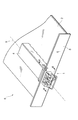
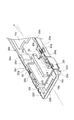
図1は、光モジュール1と、ホストボード2と、ケージ4とを含む光モジュール生産物6の斜視図である。図2は、ケージ4を一部破断して示す斜視図である。以下、本明細書において方向を示す語のうち「上下」については、ホストボード2の上方からケージ4を取り付けた状態、すなわち、図1に示す状態を基準とする。また、「前後」については、ケージ4への光モジュール1の挿入方向を後とし、光モジュール1を取り出す方向を前としている。また、「内外」については、ケージ4の中心軸線に向かう方向を内としている。
FIG. 1 is a perspective view of an
ケージ4は、所定軸X方向に延びる一対の側壁4a及び上壁4bとを有している。一対の側壁4a及び上壁4bは、光モジュール1を収容するための収容空間4cを規定している。ケージ4の前方端4dは光モジュール1を収容空間4cに受容するために開口されている。この開口は、ホストボード2の前面を構成するフロントパネル8に設けられた開口と連通している。
The cage 4 has a pair of
一対の側壁4aの各々には、ロック片4eが設けられている。ロック片4eは、側壁4aから切り出されたものである。ロック片4eは、その端部4fがケージ4の後端を向くように、収容空間4cへ突出されている。ロック片4eは、収容空間4cの外側に向けて屈曲可能とされている。
Each of the pair of
一対の側壁4aの所定軸X方向に延びる縁部には、所定の間隔を隔てて複数のピン4hが設けられている。ピン4hが、ホストボード2に設けられた孔に埋め込まれることによって、ケージ4はホストボード2に固定される。このようにホストボードに取り付けられたケージ4には、上記の前方端4dの開口から光モジュール1が装着される。
A plurality of
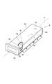
図3は、光モジュール1の斜視図である。また、図4は、光モジュール1の分解斜視図である。光モジュール1は、光ユニット10と、ホルダベース12、ホルダ14、レセプタクル部材16と、ハウジング18と、アクチュエータ20と、ベール22とを備える。
FIG. 3 is a perspective view of the
光ユニット10は、光電返還素子を搭載している。本実施形態では、光ユニット10は、発光ユニット10a、受光ユニット10b、回路基板10c、発光ユニット10aと回路基板10cとを電気的に接続する接続部品10d、及び受光ユニット10bと回路基板10cとを電気的に接続する接続部品10eを有している。
The
発光ユニット10aは、半導体レーザといった発光素子を搭載している。発光ユニット10aは、回路基板10cから接続部品10dを介して供給される電気信号に基づいて所定軸X方向に光を出射する。接続部品10dは、本実施形態では、フレキシブルプリント基板であるが、リードピンも適用可能である。
The
受光ユニット10bは、フォトダイオードといった受光素子を搭載している。受光ユニット10bは、所定軸X方向から入射する光の強度に応じた光電流を接続部品10eを介して回路基板10cに出力する。接続部品10eは、本実施形態では、フレキシブルプリント基板であるが、リードピンも適用可能である。
The
回路基板10cは、所定軸X方向に延びており、その一端には接続部品10d及び10eが接続されている。回路基板10cの他端10fは、ホストボード2に設けられた電気コネクタ(図示せず)と電気的に接続可能なカードエッジコネクタとされている。
The
回路基板10cは、所定軸X方向に延びる縁部10gの一端、及び縁部10gと反対側の縁部10hの一端には段部10iが設けられている。また、縁部10gの他端には、一方の基板面から反対側の基板面まで延びる孔10jが設けられている。
The
発光ユニット10a及び受光ユニット10bは、ホルダベース12に装着されている。ホルダベース12は、所定軸Xに交差する前壁12a、所定軸Xに交差する方向に延びる一対の側壁12b、発光ユニット10aと受光ユニット10bが装着される空間を隔する隔壁12cを有している。
The
前壁12aには、発光ユニット10aの頭部と受光ユニット10bの頭部とが挿入される開口が形成されている。側壁12b及び隔壁12cには所定軸Xに交差する方向に延びる溝12dが設けられている。溝12dにホルダ14が嵌め込まれることによって、発光ユニット10a及び受光ユニット10bが、ホルダベース12に固定される。発光ユニット10a及び受光ユニット10bが装着されたホルダベース12は、レセプタクル部材16に装着される。
The
レセプタクル部材16は、所定軸X方向に延びる一対の側壁16a、所定軸X方向に延びる隔壁16b、側壁16a及び隔壁16bに交差する面に沿い所定軸X方向に延びる下壁16cを有している。
The
レセプタクル部材16には、側壁16a及び隔壁16bによって規定されるレセプタクル16d及び16eが設けられている。レセプタクル16d及び16eは、所定軸X方向に延びており、一端の開口から挿入される光コネクタ24を受容する。レセプタクル部材16の他端には、上述したようにホルダベース12が装着されており、レセプタクル16dの他端には、ホルダベース12に装着された発光ユニット10aが挿入される。また、レセプタクル16eには、受光ユニット10bが挿入される。レセプタクル16d及び16eは、発光ユニット10a及び受光ユニット10bと光コネクタ24に保持された光ファイバとを光学的に結合する。
The
レセプタクル部材16は、表面にNiめっきを施した樹脂製であることが好ましい。かかる材料によってレセプタクル部材16を構成することによって、寸法精度、ノイズ耐性を得ることができる。なお、レセプタクル部材16は、Zn合金製であっても良い。
The
レセプタクル部材16の側壁16a及び隔壁16bの内面には、所定軸X方向に延びる溝16fが設けられている。レセプタクル部材16gには、この溝16fに交差する溝16gが、レセプタクル部材16の上部へ延びるように設けられている。光コネクタ24には、ラッチ爪24aが設けられており、ラッチ爪24aには所定軸Xに交差する方向に突出された係合部24bが設けられている。光コネクタ24の挿入時には、ラッチ爪24aを押下して溝16fに沿って係合部24bを通過させ、溝16gの位置でラッチ爪24aを解放すると、溝16gに係合部24bが係り合い、光コネクタ24がレセプタクル部材16に固定される。
ハウジング18は、第1の部材26と第2の部材28とを含んでいる。第1の部材26は、所定軸X方向に延びる一対の側壁26aと、側壁26aと交差する面に沿い、かつ、所定軸X方向に延びる上壁26bを有している。第1の部材26は、回路基板10cの一方の面を覆うように設けられている。第1の部材26は、放熱シリコーンシート等(図示せず)を介して回路基板10cと接触させることができる。第1の部材26は、アルミ合金製であることが好ましい。かかる材料を用いて第1の部材26を構成することによって、回路基板10c上の実装部品の熱が第1の部材26を介して拡散されるので、光モジュール1の放熱性を高めることができる。
The
第1の部材26の側壁26aは、所定の位置において凹状に切り欠かれた形状を有している。この凹状に切りかかれた部分の一端の段部26cに回路基板10cの段部10iが接し、他端にから突出された突起26dが回路基板10cの孔10jに嵌り合い、回路基板10cが第1の部材26に固定される。
The
第1の部材26の側壁26aの一端の内壁には、所定軸Xに交差する方向に延びる溝26eと凸部26fが設けられている。レセプタクル部材16の側壁16aの外面には、所定軸Xに交差する方向に延びる突起16hと、溝16iが設けられている。溝26eと突起16h、凸部26fと溝16iが係合することによって、レセプタクル部材16が第1の部材26に保持される。このように第1の部材26の側壁26aがレセプタクル部材16の側壁を覆うように設けられることによって、レセプタクル部材16近傍の放熱性を高めることができる。
The inner wall at one end of the
第2の部材28は、所定軸X方向に延びる一対の側壁28aと、側壁28aに交差する面に沿い、かつ、所定軸Xに沿って延びる下壁28bを有している。第2の部材28は、回路基板10cの他方の面を覆うように設けられている。また、側壁28aは、第1の部材26の側壁26aを外側から覆うように設けられている。
The
第2の部材28は、側壁28aから切り出され屈曲されたばね28cを有している。また、第2の部材28の後方端には、下壁28bから切り出されて前方端へ向けて屈曲されたばね28dが設けられている。ばね28cが回路基板10cの縁部10g及び10hを押さえつけ、また、ばね28dが回路基板10cの縁部10hの端部に設けられた段部10kを押さえつけることによって、回路基板10cが第2の部材28に固定される。
The
第2の部材28は、ばね用合金で構成されることが好ましい。ばね用合金としては、ステンレスやリン青銅が例示される。かかる材料を用いて第2の部材28を構成することによって、第2の部材28は、回路基板10cを押さえ込み、また、回路基板10cをシールドすることができる。
The
第2の部材28の側壁28aには、一端部に孔28e、他端部に孔28fが設けられている。孔28eに第1の部材26の側壁26aの一端部に設けられた突起26gが嵌め込まれ、孔28fに第1の部材26の側壁26aの他端部に設けられた突起26hがはめ込まれるることによって、第2の部材28が第1の部材26に固定される。
The
第1の部材26の側壁26aの外壁には、後述するアクチュエータの側部20aが収容される溝26iが所定軸X方向に延びるように設けられている。この溝26iの後端には、ロック部26jが設けられている。
On the outer wall of the
ロック部26jは、溝26iの後端から、前方に向けて設けられている。ロック部26jの端部には、所定軸Xに交差する面に沿うロック面26kが設けられている。ロック面26kは、光モジュール1がケージ4に挿入されたときに、ロック片4eの端部4fに対向することによって、光モジュール1がケージ4に固定される。
The
第2の部材28の側壁28aは、ロック片4eをロック部26jと対向させるために、ロック部26jと対向する位置に開口が設けられている。この開口から、ロック片4eが、収容空間4cに向けて挿入される。
The
アクチュエータ20は、所定軸X方向に延びる一対の側部20aと、側部20aを連結する連結部20bとを有している。側部20aは、第1の部材26の溝26iに収容される。溝26iに収容されることによって、側部20aは第1の部材26の側壁26aと第2の部材28の側壁28aとによって保持されるので、アクチュエータ20を所定軸X方向に安定して前後に移動させることができる。
The
側部20aの先端には、ロック解除部20cが設けられている。ロック解除部20cは、ロック部26jの一対の縁部26mに沿う二股形状をなしている。ロック解除部20cは、アクチュエータを前方へ移動させたときに、端部4fに接してロック片4eを外側へ押し出すように、その先端に向けて外側に屈曲されている。ロック解除部20cは外側に屈曲された二股形状を有するので、ロック片4eが変形していても、ロック解除部20cがロック片4eを確実に外側へ押し出すので、ロック部26jとロック片4eとのラッチを確実に解除することができる。
An unlocking
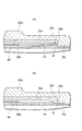
図5(a)は、図1のV−V断面図であり、光モジュール1をケージ4に固定した状態を示している。光モジュール1がケージ4に固定された状態では、ロック解除部20cは、ロック部26jの縁部26mに沿うように配置されている。
FIG. 5A is a cross-sectional view taken along the line VV in FIG. 1 and shows a state where the
図5(b)は、図1のV−V断面図であり、光モジュール1をケージ4から解放した状態を示している。光モジュール1をケージ4から解放するためにアクチュエータ20を前方へ移動させると、ロック部26jのロック面26kと対向する位置からロック片4eの端部4fがロック解除部20cによって外側に押し出され、光モジュール1がケージ4から解放される。
FIG. 5B is a cross-sectional view taken along the line VV in FIG. 1 and shows a state where the
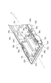
連結部20bの後端には、所定軸Xに交差する面に沿うように突起20dが設けられている。突起20dは、レセプタクル16d及び16eの内部に突出するように設けられている。図6は、図1のVI−VI線に沿って破断して示す光モジュール1の斜視図である。レセプタクル部材16の下壁16cの後端部には、突起20dをレセプタクル16d及び16eの内部に突出させるためのガイド孔16kが設けられている。突起20dは、このガイド孔16kからレセプタクル16d及び16eの内部へ突出されている。突起20dは、レセプタクル16d及び16eにおいて、光コネクタ24の端部の周縁に接するように設けられている。光コネクタ24のレセプタクル16d及び16eへの挿入時に、係合部24bがレセプタクル部材16の溝16gに係合することによって、光コネクタ24がレセプタクル部材16に固定される。光コネクタ24がレセプタクル部材16に固定された状態では、アクチュエータ20を引き出そうとしても、突起20dが光コネクタ24の端部の周縁に突き当たるので、アクチュエータ20を引き出すことができなくなる。なお、突起20dと光コネクタ24が接する幅は、光コネクタ24の端部の幅の1/3以下であることが好ましい。かかる構成によれば、光コネクタ24がレセプタクルに挿入された際の光コネクタ24の姿勢を制約する側壁16a、隔壁16b、及び下壁16cの機能が、レセプタクル部材16のガイド孔16kによって阻害されない。
A
ガイド孔16kは、突起20dを第1の位置から第2の位置へ案内するよう所定軸X方向に延びている。突起20dは、このガイド孔16kに沿って第1の位置から第2の位置へ移動可能である。第1の位置はガイド孔16kの後方端であり、突起20dは、光コネクタ24がレセプタクル16d及び16eに挿入されたときに第1の位置へ移動する。この第1の位置において、突起20dは、レセプタクル部材16に固定された光コネクタ24によって移動が制限される。したがって、レセプタクル部材16に光コネクタ24が固定された状態では、アクチュエータ20を移動させることができず、光モジュール1をケージ4から取り外すことができない。したがって、光モジュール1は、光コネクタ24の装着時にケージ4から取り外すことができない安全構造とされている。
The
第2の位置は、ガイド孔16kの前方端であり、突起20dは、光コネクタ24がレセプタクル部材16に固定されていないときに第2の位置へ移動可能である。アクチュエータ20を前方へ移動させて、突起20dを第2の位置へ移動させると、ロック解除部20cによってロック片4eが外側へ押し出され、光モジュール1がケージ4から解放される。このように、所定軸X方向にアクチュエータを移動させることによって、光モジュール1をケージ4から取り外すことができるので、この光モジュール1は、所定軸Xに交差する方向に多段に積み重ねて用いることができる。
The second position is the front end of the
さらに、連結部20bの前端には、所定軸Xに交差する面に沿うように屈曲された把持部20eが設けられている。把持部20eは、後述するベール22を用いない場合でも、この把持部20eを操作することによって、アクチュエータ20を所定軸X方向へ移動できるようにするために設けられている。
Furthermore, a
図4に示すように、アクチュエータ20の側部20aには、所定軸Xに交差する方向に孔20fを設けることができる。また、この孔20fに連続して、所定軸X方向に長径が位置する長孔28hを第2の部材28の側壁28aに設けることができる。この孔20fにベール22の軸部22aを挿入することによって、ベール22をアクチュエータ20に取り付けることができる。
As shown in FIG. 4, a
本実施形態では、ベール22の軸部22aは、所定軸Xに交差する方向に延びており、この軸部22aは、孔20fに軸支されている。また、ベール22は、所定軸X方向に延びるグリップ部22bを有している。グリップ部22bは、レセプタクル部材16の開口端前方を旋回可能である。光モジュール1をケージ4から解放するためにベール22が前方へ引き出されると、ベール22が長孔28hに沿って移動すると共に、アクチュエータ20が前方へ引き出される。
In the present embodiment, the
一方、レセプタクル部材16に光コネクタ24を装着したときには、ベール22のグリップ部22bをレセプタクル部材16の上方または下方に移動させることができる。ここで、本実施形態の光モジュール1では、長孔28hの後方端に、長孔28hに交差する長孔28iが設けられている。ベール22のグリップ部22bをレセプタクル部材16の上方または下方に移動させると、この長孔28iにベール22の内径部22cが嵌り合い、ベール22を固定することができる。
On the other hand, when the
このように、光モジュール1では、ベール22が設けられているので、アクチュエータ20の操作が更に容易とされている。また、光モジュール1では、光コネクタ24をレセプタクル部材16に装着したときに、ベール22をレセプタクル部材の上方に配置しても、下方に配置しても良い。したがって、光モジュール1を所定軸Xに交差する方向に2段に重ねて用いることも可能である。
Thus, in the
[第2実施形態]
本発明の第2実施形態にかかる光モジュール1aについて説明する。図7は、光モジュール1aの分解斜視図である。光モジュール1aは、第1実施形態の光モジュール1と同様に、光ユニット10と、ホルダベース12、ホルダ14、レセプタクル部材16と、ハウジング18と、アクチュエータ20と、ベール22とを備える。光モジュール1aでは、ハウジング18の第1の部材26、アクチュエータ20、ベール22が第1実施形態と異なる。さらに、光モジュール1aは、押圧部材30を有している。
[Second Embodiment]
An
図7に示されるように、アクチュエータ20の側部20aには、軸20iが更に設けられている。この軸20iは、側部20aから切り出され、アクチュエータ20の中心軸線に向けて屈曲されたものである。側部20aと連結部20bとの境界は、アクチュエータ20の前方端から所定長切りかかれている。また、側部20aの前方端は、外側へ屈曲されている。
As shown in FIG. 7, a
ベール22は、グリップ部22bと、グリップ部22bに交差する方向に延びる一対の側柱22dを有している。側柱22dには、孔22eが設けられている。側柱22dが側部20aと連結部20bとの境界の切り欠きを通り、孔22eに軸20iが通されることによって、ベール22は軸20iに軸支される。
The
アクチュエータ20は、側部20aに爪20gを更に有している。爪20gは、側部20aから切り出され、アクチュエータ20の中心軸線に向けて屈曲されている。爪20gは、所定軸Xに交差する面に沿うように設けられている。
The
第1の部材26の一対の側壁26a各々には、ガイド溝26pが更に設けられている。ガイド溝26pは、所定軸Xに交差する面に沿う一端面26qから他端面26rまで所定軸X方向に延びている。ガイド溝26pには、アクチュエータ20の爪20gが挿入される。
Each of the pair of
一端面26qと爪20gとの間には、押圧部材30が設けられている。本実施形態では、押圧部材30としてコイルバネが例示されている。
A pressing
図8は、光モジュール1aを破断して示す斜視図であり、アクチュエータ20が光モジュール1aの後方へ向けて押し込まれた状態を示す。押圧部材30は、自由状態では、爪20gが他端面26rに当接するようにアクチュエータ20を押圧する。この状態において、アクチュエータ20の突起20dはガイド孔16kの後方端に位置する。すなわち、押圧部材30は、ロック部26jとロック片4eとのラッチが解除されないように、アクチュエータ20の位置を保つ。
FIG. 8 is a cutaway perspective view of the
図9は、光モジュール1aを破断して示す斜視図であり、アクチュエータ20が引き出された状態を示している。前方に引き出す方向へアクチュエータ20に力が加わると、爪20gによって押圧部材30が縮められる。押圧部材30が縮められることによってアクチュエータ20が引き出され、ロック部26jとロック片4eとのラッチが解除される。なお、アクチュエータ20が引き出された状態においてもアクチュエータ20の側部20aはガイド溝26pの開口の一部を塞ぎ、ガイド溝26pから飛び出さないように押圧部材30をサポートしている。
FIG. 9 is a perspective view showing the
以上説明したように、第2実施形態の光モジュール1aでは、押圧部材30によってアクチュエータ20が光モジュール1aの後方へ押圧される。すなわち、光コネクタ24がレセプタクル部材16に固定されていない状態であっても、ロック部26jとロック片4eとのラッチが解除されないように、押圧部材30によってアクチュエータ20の位置が保たれる。したがって、押圧部材30を縮ませる力がアクチュエータ20に働かない限り、光モジュール1とケージ4とのラッチが解除されることがない。
As described above, in the
[第3実施形態]
本発明の第3実施形態にかかる光モジュール1bについて説明する。図10は、光モジュール1bの分解斜視図である。光モジュール1bは、第2実施形態の光モジュール1aと同様に、光ユニット10と、ホルダベース12、ホルダ14、レセプタクル部材16と、ハウジング18と、アクチュエータ20と、ベール22と、押圧部材(付勢部材)30を備える。光モジュール1bでは、ハウジング18の第1の部材26、アクチュエータ20、ベール22が第2実施形態と異なる。以下、第3実施形態の第1の部材26、アクチュエータ20、ベール22に関し、第2実施形態と異なる点について説明する。
[Third Embodiment]
An
図10に示すように、第3実施形態の第1の部材26では、後述するアクチュエータ20の側部20aの前方端部20jを収容するために、側壁26aの前方端部が、溝26iの底面と同様の高さになっている。また、側壁26aの前方端には、所定軸Xに交差する回転軸Yに沿って、軸26tが外側に延出している。
As shown in FIG. 10, in the
第3実施形態のベール22では、一対の側柱22dに、回転軸Y方向に延びる孔22fが、それぞれ設けられている。また、一対の側柱22dには、回転軸Y方向に外側へ延出する突起22gがそれぞれ設けられている。ベール22は、孔22fに軸26tが挿入されることによって、第1の部材26(ハウジング18)に軸支され、回転軸Y中心の回転が可能になっている。
In the
第3実施形態のアクチュエータ20では、一対の側部20aの前方端部20j各々に、摺動面20kを提供する孔20mが設けられている。摺動面20kは、所定軸Xに交差する面に沿って設けられている。突起22gは、孔20mに挿入され、ベール22の回転軸Y中心の回転によって、摺動面20kに摺動し、アクチュエータ20を、所定軸X方向に駆動する。
In the
図11は、第3実施形態にかかる光モジュールの一部を拡大した斜視図であり、ケージへのロック時におけるアクチュエータ20の位置とベール22の位置との関係を示す。また、図12は、第3実施形態にかかる光モジュールの一部を拡大した斜視図であり、ロック解除時のアクチュエータ20の位置とベール22の位置との関係を示す。なお、図11及び図12では、第2の部材28を除いて光モジュール1bが示されている。
FIG. 11 is an enlarged perspective view of a part of the optical module according to the third embodiment, and shows the relationship between the position of the
アクチュエータ20の爪20gは押圧部材30によって付勢されており、ガイド溝26pの他端面26r、すなわち、ケージ4の後端に向けて付勢されている。押圧部材30としては、コイルばねが例示される。図11に示すように、押圧部材30が自由状態の場合には、アクチュエータ20のロック解除部20cは、ロック部26jとケージ4のロック片4eとによるロックを非解除とするロック位置に位置する。このとき、突起22gは、摺動面20kによってケージ4の後端に向けて駆動されており、ベール22のグリップ部22bが、レセプタクル部材16の上方に位置するようになっている。
The
一方、図11に示す状態から図12に示す状態に、ベール22が回転されると、突起22gが摺動面20kと摺動しつつ、アクチュエータ20を所定軸X方向に前方へ駆動する。図11に示す状態から図12に示す状態へアクチュエータ20が移動するストローク長は、ロック部26jとロック片4eとによるロックを解除するロック解除位置へロック解除部20cを移動させる長さになっている。
On the other hand, when the
以上説明した第3実施形態に係る光モジュール1bによれば、ベール22の回転動作によって、ロック片4eとロック部26cとによるロックが解除又は非解除となるよう、ロック解除部20cを移動させることができる。また、アクチュエータ20が押圧部材30によって付勢されるので、平常時においては、ロック片4eとロック部26cとがロック状態になるように、ベール22の位置が自動的に保たれる。
According to the
なお、軸26tに代えて、第1の部材26(ハウジング18)に回転軸Y方向に延びる孔を軸受として設け、孔22fに代えて当該軸受によって軸支される軸をベール22に設けてもよい。
Instead of the
1…光モジュール、2…ホストボード、4…ケージ、4a…側壁、4c…収容空間、4e…ロック片、4f…端部、6…光モジュール生産物、8…フロントパネル、10…光ユニット、12…ホルダベース、14…ホルダ、16…レセプタクル部材、16d,16e…レセプタクル、16k…ガイド孔、18…ハウジング、20…アクチュエータ、20c…ロック解除部、20d…突起、22…ベール、24…光コネクタ、26…第1の部材、28…第2の部材。
DESCRIPTION OF
Claims (10)
光電変換素子が搭載された光ユニットと、
前記所定の収容空間に収容されたときに前記ロック片の端部と対向するロック面を含むロック部を有するハウジングと、
前記所定軸方向に延び、一端から挿入される光コネクタを受容し他端に前記光ユニットが装着されるレセプタクルを規定する壁部を有し、該壁部にガイド孔が設けられたレセプタクル部材と、
前記ガイド孔に沿って第1の位置から第2の位置へ前記所定軸方向に移動可能な部材であり、前記ガイド孔からレセプタクル内部に突出された突起と、前記第2の位置への移動時に前記ロック片を前記所定の収容空間の外側に向けて駆動するロック解除部とを有するアクチュエータと
を備える光モジュール。 A wall portion defining a predetermined accommodation space extending in a predetermined axial direction and having one end opened; an end projecting into the predetermined accommodation space so as to face the other end opposite to the one end; and the end portion An optical module provided with a pair of edge portions extending to the wall portion and having a locking piece that is bent and supported by the wall portion and is inserted into the predetermined accommodation space of the cage mounted on the host board. And
An optical unit equipped with a photoelectric conversion element;
A housing having a lock portion including a lock surface facing the end of the lock piece when housed in the predetermined housing space;
A receptacle member that extends in the predetermined axial direction, has a wall portion that receives an optical connector inserted from one end and defines a receptacle to which the optical unit is mounted at the other end, and a guide hole is provided in the wall portion; ,
A member that is movable in the predetermined axial direction from the first position to the second position along the guide hole, and a protrusion that protrudes from the guide hole into the receptacle, and at the time of movement to the second position. An optical module comprising: an actuator having a lock release unit that drives the lock piece toward the outside of the predetermined accommodation space.
前記ロック解除部は、前記ロック部の一対の縁に沿うように延びる二股形状をなしており、前記第2の位置への移動時に前記ロック片の端部に接する
ことを特徴とする請求項1または2に記載の光モジュール。 The lock portion has a pair of edges extending in a predetermined axial direction,
2. The lock release portion has a bifurcated shape extending along a pair of edges of the lock portion, and contacts the end of the lock piece when moving to the second position. Or the optical module of 2.
前記第1の部材は、所定軸方向に延びる一対の側壁を有し、
前記第2の部材は、所定軸方向に延び前記第1の部材の一対の側壁を囲むように設けられた一対の側壁を有し、
前記アクチュエータは、一端に前記ロック解除部が設けられ前記第1の部材の側壁と前記第2の部材の側壁との間に収容される側部を有し、
前記第1の部材の側壁には、前記ロック部が設けられており、
前記第2の部材の側壁には、前記ロック片が挿入される開口が設けられている
ことを特徴とする請求項1〜3のいずれか1項に記載の光モジュール。 The housing includes a first member and a second member;
The first member has a pair of side walls extending in a predetermined axial direction,
The second member has a pair of side walls provided in a predetermined axial direction so as to surround the pair of side walls of the first member,
The actuator has a side portion provided with the unlocking portion at one end and housed between the side wall of the first member and the side wall of the second member,
The lock portion is provided on a side wall of the first member,
The optical module according to claim 1, wherein an opening into which the lock piece is inserted is provided on a side wall of the second member.
前記レセプタクル部材は、表面に金属膜が設けられた樹脂製である
ことを特徴とする請求項1〜4のいずれか1項に記載の光モジュール。 The first member is made of metal,
The optical module according to claim 1, wherein the receptacle member is made of a resin having a metal film provided on a surface thereof.
前記第1の部材一対の側壁及び前記第2の部材の一対の側壁各々には、前記孔に連続し前記所定軸方向に長径が位置する長孔が設けられており、
前記孔に軸支され前記レセプタクル部材の一端前方を旋回可能に設けられたベールを更に備える
ことを特徴とする請求項4〜6のいずれか1項に記載の光モジュール。 Each of the pair of side portions of the actuator is formed with a hole extending in a direction intersecting a predetermined axis,
Each of the pair of side walls of the first member and the pair of side walls of the second member is provided with a long hole that is continuous with the hole and has a long diameter in the predetermined axial direction.
The optical module according to any one of claims 4 to 6, further comprising a bail that is pivotally supported by the hole and is provided so as to be rotatable in front of one end of the receptacle member.
前記アクチュエータには、前記一端面に対向する面を有し前記ガイド溝に挿入される爪が設けられており、
前記一端面と前記爪との間には、前記突起が前記第1の位置へ向かうように前記アクチュエータを押圧する押圧部材が設けられている、請求項1〜7のいずれか1項に記載の光モジュール。 The housing is further provided with a guide groove having one end surface along a surface intersecting the predetermined axis,
The actuator is provided with a claw having a surface facing the one end surface and inserted into the guide groove,
The pressing member according to any one of claims 1 to 7, wherein a pressing member that presses the actuator is provided between the one end surface and the claw so that the protrusion is directed to the first position. Optical module.
前記アクチュエータは、前記ベールの回転時に前記ベールの突起が摺動する摺動面を更に有し、
前記ベールの突起は、前記ベールの回転によって、前記ロック片と前記ロック部とのロックを非解除とするロック位置と、前記ロック片と前記ロック部とによるロックを解除するロック解除位置との間で、前記ロック解除部を移動させるよう、前記アクチュエータを駆動する、請求項1〜6の何れか1項に記載の光モジュール。 A member pivotally supported on the housing so as to be rotatable about a rotation axis that intersects the predetermined axis, further comprising a bail having a protrusion extending in the rotation axis direction;
The actuator further includes a sliding surface on which the projection of the bale slides when the bale rotates.
The protrusion of the bale is between a lock position where the lock of the lock piece and the lock part is not released by the rotation of the bale, and a lock release position where the lock of the lock piece and the lock part is released. The optical module according to claim 1, wherein the actuator is driven to move the lock release unit.
The optical module according to claim 9, further comprising a biasing member that biases the actuator toward the other end of the cage.
Priority Applications (1)
| Application Number | Priority Date | Filing Date | Title |
|---|---|---|---|
| JP2004123280A JP4200931B2 (en) | 2003-05-30 | 2004-04-19 | Optical module |
Applications Claiming Priority (3)
| Application Number | Priority Date | Filing Date | Title |
|---|---|---|---|
| JP2003155456 | 2003-05-30 | ||
| JP2003329102 | 2003-09-19 | ||
| JP2004123280A JP4200931B2 (en) | 2003-05-30 | 2004-04-19 | Optical module |
Publications (2)
| Publication Number | Publication Date |
|---|---|
| JP2005115324A JP2005115324A (en) | 2005-04-28 |
| JP4200931B2 true JP4200931B2 (en) | 2008-12-24 |
Family
ID=34556975
Family Applications (1)
| Application Number | Title | Priority Date | Filing Date |
|---|---|---|---|
| JP2004123280A Expired - Lifetime JP4200931B2 (en) | 2003-05-30 | 2004-04-19 | Optical module |
Country Status (1)
| Country | Link |
|---|---|
| JP (1) | JP4200931B2 (en) |
Families Citing this family (5)
| Publication number | Priority date | Publication date | Assignee | Title |
|---|---|---|---|---|
| MX2014014008A (en) | 2012-05-18 | 2015-06-10 | Adc Telecommunications Inc | Connectors and adapters with auto-latching features. |
| US9075205B2 (en) | 2012-07-11 | 2015-07-07 | Tyco Electronics Corporation | Connectors and adapters with auto-latching features |
| JP5282838B2 (en) * | 2012-08-07 | 2013-09-04 | 日立電線株式会社 | Photoelectric conversion module |
| US9709763B2 (en) * | 2014-06-16 | 2017-07-18 | Finisar Corporation | Pluggable connector |
| JP2017015888A (en) * | 2015-06-30 | 2017-01-19 | 富士通コンポーネント株式会社 | Optical module |
-
2004
- 2004-04-19 JP JP2004123280A patent/JP4200931B2/en not_active Expired - Lifetime
Also Published As
| Publication number | Publication date |
|---|---|
| JP2005115324A (en) | 2005-04-28 |
Similar Documents
| Publication | Publication Date | Title |
|---|---|---|
| US7303336B2 (en) | Transceiver module | |
| US6430053B1 (en) | Pluggable transceiver module having rotatable release and removal lever with living hinge | |
| US7114984B2 (en) | Lever style de-latch mechanism for pluggable electronic module | |
| EP1548896B1 (en) | Module connect/disconnect structure and method for disconnecting a module using the structure | |
| US6881095B2 (en) | Small form-factor transceiver module with pull-to-release | |
| JP5797018B2 (en) | Cable assembly latch | |
| JP5546982B2 (en) | Photoelectric composite connector | |
| US20050018979A1 (en) | Optical module having a simple mechanism for releasing from a cage | |
| JP4338960B2 (en) | Optical module locking mechanism | |
| US20120294571A1 (en) | Connector element containing a locking mechanism | |
| KR100637636B1 (en) | Optical module capable of facilitating release from locking state with cage which accommodates optical module | |
| JP2004343506A (en) | Optical module, and method for releasing locked state of optical module and cage | |
| US20060068628A1 (en) | Package with locking mechanism and optical transceiver | |
| US20080220643A1 (en) | Land grid array connector having improved cover | |
| US7033208B1 (en) | Flexible printed circuit connector | |
| JP2008243554A (en) | Cable connector | |
| KR20160090738A (en) | Card Tray and Card Connector | |
| JP4200931B2 (en) | Optical module | |
| US20100119196A1 (en) | Optical connector with improved retaining element | |
| JPH097556A (en) | Battery configuration unit for hand-carried type machine tool | |
| US6027351A (en) | Card connector | |
| US7059887B1 (en) | Optoelectric module with pop-out tab based latching/delatching mechanism | |
| JP2005300979A (en) | Lock releasing mechanism of optical module, optical module and method to release locked condition of the optical module and cage | |
| JP4186917B2 (en) | Optical module | |
| JP4096829B2 (en) | Optical module |
Legal Events
| Date | Code | Title | Description |
|---|---|---|---|
| A621 | Written request for application examination |
Free format text: JAPANESE INTERMEDIATE CODE: A621 Effective date: 20070315 |
|
| A977 | Report on retrieval |
Free format text: JAPANESE INTERMEDIATE CODE: A971007 Effective date: 20080902 |
|
| TRDD | Decision of grant or rejection written | ||
| A01 | Written decision to grant a patent or to grant a registration (utility model) |
Free format text: JAPANESE INTERMEDIATE CODE: A01 Effective date: 20080916 |
|
| A01 | Written decision to grant a patent or to grant a registration (utility model) |
Free format text: JAPANESE INTERMEDIATE CODE: A01 |
|
| A61 | First payment of annual fees (during grant procedure) |
Free format text: JAPANESE INTERMEDIATE CODE: A61 Effective date: 20080929 |
|
| R150 | Certificate of patent or registration of utility model |
Ref document number: 4200931 Country of ref document: JP Free format text: JAPANESE INTERMEDIATE CODE: R150 Free format text: JAPANESE INTERMEDIATE CODE: R150 |
|
| FPAY | Renewal fee payment (event date is renewal date of database) |
Free format text: PAYMENT UNTIL: 20111017 Year of fee payment: 3 |
|
| FPAY | Renewal fee payment (event date is renewal date of database) |
Free format text: PAYMENT UNTIL: 20121017 Year of fee payment: 4 |
|
| FPAY | Renewal fee payment (event date is renewal date of database) |
Free format text: PAYMENT UNTIL: 20131017 Year of fee payment: 5 |
|
| R250 | Receipt of annual fees |
Free format text: JAPANESE INTERMEDIATE CODE: R250 |
|
| R250 | Receipt of annual fees |
Free format text: JAPANESE INTERMEDIATE CODE: R250 |
|
| R250 | Receipt of annual fees |
Free format text: JAPANESE INTERMEDIATE CODE: R250 |
|
| R250 | Receipt of annual fees |
Free format text: JAPANESE INTERMEDIATE CODE: R250 |
|
| R250 | Receipt of annual fees |
Free format text: JAPANESE INTERMEDIATE CODE: R250 |
|
| R250 | Receipt of annual fees |
Free format text: JAPANESE INTERMEDIATE CODE: R250 |
|
| R250 | Receipt of annual fees |
Free format text: JAPANESE INTERMEDIATE CODE: R250 |
|
| R250 | Receipt of annual fees |
Free format text: JAPANESE INTERMEDIATE CODE: R250 |
|
| R250 | Receipt of annual fees |
Free format text: JAPANESE INTERMEDIATE CODE: R250 |
|
| R250 | Receipt of annual fees |
Free format text: JAPANESE INTERMEDIATE CODE: R250 |