JP4200747B2 - Movement information classification device, movement information classification method, and movement information classification program - Google Patents
Movement information classification device, movement information classification method, and movement information classification program Download PDFInfo
- Publication number
- JP4200747B2 JP4200747B2 JP2002344699A JP2002344699A JP4200747B2 JP 4200747 B2 JP4200747 B2 JP 4200747B2 JP 2002344699 A JP2002344699 A JP 2002344699A JP 2002344699 A JP2002344699 A JP 2002344699A JP 4200747 B2 JP4200747 B2 JP 4200747B2
- Authority
- JP
- Japan
- Prior art keywords
- time
- information
- movement
- travel
- specifying
- Prior art date
- Legal status (The legal status is an assumption and is not a legal conclusion. Google has not performed a legal analysis and makes no representation as to the accuracy of the status listed.)
- Expired - Fee Related
Links
Images


Landscapes
- Information Retrieval, Db Structures And Fs Structures Therefor (AREA)
- Traffic Control Systems (AREA)
- Mobile Radio Communication Systems (AREA)
Description
【0001】
【発明の属する技術分野】
この発明は、移動情報分類装置、移動情報分類方法、及び移動情報分類プログラムに関し、特に、移動体の移動位置や移動時間等の移動情報を効率よく分類する移動情報分類装置、移動情報分類方法、及び移動情報分類プログラムに関する。
【0002】
【従来の技術】
近年、カーナビゲーションシステムが広く普及してきている。カーナビゲーションシステムは、地図データ等を参照して目的地までのルート探索を行うほか、GPS(Global Positioning System)等を利用して自車位置を測定し、これを地図上に表示する。
【0003】
また、最近のカーナビゲーションシステムでは、FM放送等を受信して道路の渋滞情報等を取得し、渋滞箇所を避けたルート探索を行ったり、測定した自車位置を走行軌跡データとして時系列に記憶しておき、自車の走行軌跡を確認することができるようにしたもの等もある。
【0004】
この他にも、車両等の移動情報を収集する技術としては、様々なものがある(例えば、特許文献1、特許文献2参照)
【特許文献1】
特開平10−11688号公報
【特許文献2】
特開平11−245853号公報
【0005】
【発明が解決しようとする課題】
上述したように、カーナビゲーションシステム等のように、車両等の移動体の移動情報を収集するための技術が多く提案されている。しかしながら、収集した移動情報は、膨大な量となることが多く、情報量は多いものの、これらを効率よく、有効に利用することは困難な場合があった。
【0006】
そこで、この発明は、車両等の移動体の移動に関する移動情報を有効に、かつ効率よく利用するように分類することのできる移動情報分類装置、移動情報分類方法、及び移動情報分類プログラムを提供することを目的とする。
【0007】
【課題を解決するための手段】
上述した目的を達成するため、請求項1の発明は、移動体にて生成された、該移動体が所定の2点を結ぶ移動位置を移動するのに要した時間を特定する移動時間特定情報と該移動体が該移動位置を移動した時刻を特定する移動時刻特定情報と該移動位置を特定する移動位置特定情報とを取得する移動情報取得手段と、移動体外で生成された、前記移動位置を移動体が移動する移動時間に変動を与えた可能性を有する不定期イベントの発生を変動要因として、該変動要因を示す変動要因情報と該変動要因が発生した位置を特定する要因発生位置特定情報と該変動要因が発生した時刻を特定する時刻特定情報とを取得する変動情報取得手段と、前記移動情報取得手段により取得された移動位置特定情報により特定される移動位置と前記変動情報取得手段により取得された要因発生位置特定情報により特定される位置とが対応し、かつ、前記移動情報取得手段により取得された移動時刻特定情報により特定される時刻と前記変動情報取得手段により取得された時刻特定情報により特定される時刻とが対応する移動時間特定情報と変動要因情報とを関連付ける関連付手段と、移動時間を予測する対象となる移動位置を特定する移動位置特定手段と、前記移動情報取得手段により取得された移動時間特定情報のうち前記移動位置特定手段により特定された移動位置と同じ移動位置に対応する移動時間特定情報から前記関連付手段により変動要因情報が関連付けられた移動時間特定情報を除外した移動時間特定情報を、移動時間の予測値として利用する移動時間予測手段とを備えることを特徴とする。
【0008】
また、請求項2の発明は、請求項1の発明において、前記移動時間特定情報は、前記移動体が移動位置を移動した平均速度であることを特徴とする。
【0009】
また、請求項3の発明は、移動体にて生成された、該移動体が所定の2点を結ぶ移動位置を移動するのに要した時間を特定する移動時間特定情報と該移動体が該移動位置を移動した時刻を特定する移動時刻特定情報と該移動位置を特定する移動位置特定情報とを取得し、移動体外で生成された、前記移動位置を移動体が移動する移動時間に変動を与えた可能性を有する不定期イベントの発生を変動要因として、該変動要因を示す変動要因情報と該変動要因が発生した位置を特定する要因発生位置特定情報と該変動要因が発生した時刻を特定する時刻特定情報とを取得し、前記移動位置特定情報により特定される移動位置と前記要因発生位置特定情報により特定される位置とが対応し、かつ、前記移動時刻特定情報により特定される時刻と前記時刻特定情報により特定される時刻とが対応する移動時間特定情報と変動要因情報とを関連付け、移動時間を予測する対象となる移動位置を特定し、前記移動時間特定情報のうち前記特定された移動位置と同じ移動位置に対応する移動時間特定情報から前記変動要因情報が関連付けられた移動時間特定情報を除外した移動時間特定情報を、移動時間の予測値として利用することを特徴とする。
【0010】
また、請求項4の発明は、移動体にて生成された、該移動体が所定の2点を結ぶ移動位置を移動するのに要した時間を特定する移動時間特定情報と該移動体が該移動位置を移動した時刻を特定する移動時刻特定情報と該移動位置を特定する移動位置特定情報とを取得する移動情報取得処理と、移動体外で生成された、前記移動位置を移動体が移動する移動時間に変動を与えた可能性を有する不定期イベントの発生を変動要因として、該変動要因を示す変動要因情報と該変動要因が発生した位置を特定する要因発生位置特定情報と該変動要因が発生した時刻を特定する時刻特定情報とを取得する変動情報取得処理と、前記移動情報取得処理により取得された移動位置特定情報により特定される移動位置と前記変動情報取得処理により取得された要因発生位置特定情報により特定される位置とが対応し、かつ、前記移動情報取得処理により取得された移動時刻特定情報により特定される時刻と前記変動情報取得処理により取得された時刻特定情報により特定される時刻とが対応する移動時間特定情報と変動要因情報とを関連付ける関連付処理と、移動時間を予測する対象となる移動位置を特定する移動位置特定処理と、前記移動情報取得処理により取得された移動時間特定情報のうち前記移動位置特定処理により特定された移動位置と同じ移動位置に対応する移動時間特定情報から前記関連付処理により変動要因情報が関連付けられた移動時間特定情報を除外した移動時間特定情報を、移動時間の予測値として利用する移動時間予測処理とをコンピュータに実行させることを特徴とする。
【0019】
【発明の実施の形態】
以下、この発明に係る移動情報分類装置、移動情報分類方法、及び移動情報分類プログラムの一実施の形態について、添付図面を参照して詳細に説明するが、この説明においては、最初に目次を示し、当該目次に沿って以降の説明を行う。
【0020】
[目次]
1.概要
2.システム構成
2.1.走行ログ収集センタ
2.2.走行ログの収集
3.走行ログデータベースの構築
3.1.構築の流れ
3.2.走行ログと単位走行ログ
3.3.提供者属性
3.4.結合道路
3.5.交差点通過日時の算出
3.6.誤差の除去
3.7.結合道路所要時間データベースの構築
4.走行ログの収集
4.1.収集の流れ
4.2.走行ログの圧縮
4.3.交差点通過日時リストの送信
4.4.結合道路毎の統計処理後の送信
4.5.結合道路の特徴での統計処理後の送信
4.6.パソコンの利用
5.走行ログと提供者
5.1.プライバシーの保護
5.2.保護レベルの設定
5.3.利益供与
6.データのカーナビゲーションシステムでの利用
6.1.カーナビ構成例
6.2.ルート探索
6.3.天候毎のルート探索
6.4.不定期イベントを考慮したルート探索
6.5.到着日時指定ルート探索
7.走行ログデータベースの他の利用例
7.1.Web向けルート探索
7.2.渋滞予報
7.3.道路交通統計
7.4.コンサルティング
【0021】
[1.概要]
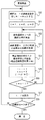
第1章では、この発明を適用した走行データ処理システムの概要について説明する。
【0022】
図1は、走行データ処理システムの概要を示した図である。同図に示すように、走行データ処理システムでは、走行ログ収集センタ10で走行軌跡データ(以下、走行ログと称する場合もある)の収集1と収集した走行ログに基づくコンテンツ事業2を行う。
【0023】
走行ログ収集1は、カーナビゲーションシステム(以下、カーナビと略称する場合もある)を利用しているカーナビユーザ3の協力の下に行い、カーナビユーザ3には、対価等の利益供与を行う。
【0024】
コンテンツ事業2は、収集した走行ログに基づいて様々な情報を生成し、生成した情報を提供する。
【0025】
例えば、走行ログに基づいて渋滞予測を加味したルート探索を行うための情報(ただし、事故渋滞を除く)をカーナビメーカー4に提供する。カーナビメーカー4は、当該情報をカーナビユーザ3への提供等に利用する。また、カーナビメーカー4に提供する情報は、別途、インターネットを利用して経路検索を行うためのWebサービス5としての提供や、情報自体を販売するデータベース販売6として提供、渋滞を予測した渋滞予報の配信7として提供できる。
【0026】
また、走行ログからは、各道路の交通量等を推測することが可能であるため、これを道路交通統計8や店舗出店計画9に利用することができる。
【0027】
[2.システム構成]
第2章では、走行データ処理システムの構成について説明する。
【0028】
図2は、走行データ処理システムの概略構成を示した図である。同図に示すように、走行データ処理システムでは、走行ログ収集センタ10が、カーナビを搭載したカーナビ搭載車11−1〜11−nからインターネット12を介して走行ログを収集する。
【0029】
そこで、走行ログ収集センタ10の構成を2.1節で、走行ログの収集のための構成を2.2節で説明する。
【0030】
[2.1.走行ログ収集センタ]
2.1節では、走行ログ収集センタ10の構成について説明する。
【0031】
図3は、走行ログ収集センタ10の構成例を示したブロック図である。同図に示すように、走行ログ収集センタ10は、送受信部21と提供者情報22、走行ログ取得部23、走行ログ処理部24、地図データベース25、走行ログデータベース26、走行ログ加工部27、結合道路所要時間データベース28を具備して構成される。
【0032】
送受信部21は、インターネット12との間で情報の送受信を行い、その情報の一つとして走行ログを受信する。提供者情報データベース22は、走行ログを提供した提供者の情報を格納するもので、ここに格納した提供者情報に基づいて対価等の利益供与を行う。ただし、提供者のプライバシー保護の観点(詳細は、第5章で説明する)から別の形態で提供者情報を管理する場合もある。
【0033】
走行ログ取得部23は、送受信部21が受信する情報から走行ログを取得し、走行ログ処理部24は、走行ログ取得部23が取得した走行ログを所定のフォーマットに変換して走行ログデータベース26に格納する。このとき、走行ログ処理部24は、必要に応じて地図データベース25を参照する。地図データベース25は、地図データを格納したものである。なお、地図データの利用法に関しては、第3章で説明する。走行ログデータベース26は、走行ログを格納・管理する。
【0034】
走行ログ加工部27は、走行ログデータベース26に格納されている走行ログに基づいて、結合道路(結合道路については、第3章で説明する)を通過する平均時間等を算出し、算出結果を結合道路所要時間データベース28に格納する。結合道路所要時間データベース28は、結合道路の通過に要する時間等の情報を格納・管理する。
【0035】
なお、走行ログ収集センタ10の各部における処理については、第3章で説明する。
【0036】
ところで、図3に示した走行ログ収集センタ10の構成例では、最終的に格納・管理している情報は、走行ログデータベース26に格納される走行ログと結合道路所要時間データベース28に格納される通過時間等である。しかしながら、走行ログ収集センタ10は、さらに多種の情報を管理することができ、その場合の構成は、別のものとなる。そこで、走行ログ収集センタ10の別の構成例についても説明する。
【0037】
図4は、走行ログ収集センタ10の別の構成例を示したブロック図である。同図に示すように、走行ログ収集センタ10は、送受信部21と提供者情報データベース22、地図データベース25、走行ログデータベース26、結合道路所要時間データベース28、データ処理部29、不定期イベント除外結合道路所要時間データベース30、不定期イベント補正値データベース31、天候データベース32、不定期イベントデータベース33を具備して構成される。
【0038】
送受信部21と提供者情報データベース22、地図データベース25、走行ログデータベース26、結合道路所要時間データベース28は、図3に示したものと同様のものである。
【0039】
データ処理部29は、図3に示した走行ログ取得部23、走行ログ処理部24、走行ログ加工部27の全ての機能を含むとともに、走行ログデータベース26に格納されている走行ログ等に基づいて、様々なデータを生成する。
【0040】
不定期イベント除外結合道路所要時間データベース30は、結合道路を通過する平均時間等のうち、不定期のイベントが発生した日時分を除外したものが格納されている。不定期のイベントとは、工事や事故、競馬、競輪、競艇、コンサート、有名人の葬式、デモ行進等がある。ただし、競馬等は、毎週開催されるものは、不定期イベントとして取り扱わないが、GIレース等のように人の出が特に多くなるようなものは、不定期イベントとして取り扱う。
【0041】
不定期イベント補正値データベース31は、不定期のイベントが発生した場合に、結合道路を通過する平均時間等を補正する値を格納するもので、この補正値を不定期イベント除外結合道路所要時間データベース30に格納されている平均時間等に適用することで、不定期イベントが発生した際の平均時間等を得ることができる。
【0042】
天候データベース32と不定期イベントデータベース33は、それぞれ天候と不定期イベントに関するデータが格納されている。なお、天候データベース32と不定期イベントデータベース33は、必ずしも走行ログ収集センタ10に配されている必要はなく、インターネット12等を介してデータを取得できる場所に配されていればよい。
【0043】
[2.2.走行ログの収集]
2.2節では、走行ログを収集するための構成について説明する。
【0044】
図5は、走行ログを収集するための構成例を示した図である。まず、図5(a)に示す構成では、カーナビ40−1は、携帯電話41と接続されている。そして、カーナビ40−1が蓄積した走行ログは、携帯電話41によりインターネット12を介して走行ログ収集センタ10に送信される。
【0045】
また、図5(b)に示す構成では、カーナビ40−2は、蓄積した走行ログをメモリカード42等の記憶媒体に記憶する。メモリカード42に記憶された走行ログは、提供者(カーナビの所有者)の自宅またはオフィス等に設置されたPC43で読み込まれ、インターネット12を介して走行ログ収集センタ10に送信される。
【0046】
また、図5(c)に示す構成では、カーナビ40−3は、無線LANに対応するLANアダプタ44と接続されている。そして、LANアダプタ44が提供者の自宅またはオフィス等に設置された宅内アクセスポイント45に接続した際に、カーナビ40−3が蓄積した走行ログは、インターネット12を介して走行ログ収集センタ10に送信される。
【0047】
さらに、図5(d)に示す構成では、図5(c)に示した構成と同様にカーナビ40−3は、無線LANに対応するLANアダプタ44と接続されている。そして、LANアダプタ44がコンビニエンスストアやガソリンスタンド、電柱、信号機等に設置された街頭アクセスポイント46に接続した際に、カーナビ40−3が蓄積した走行ログは、インターネット12を介して走行ログ収集センタ10に送信される。
【0048】
次に、走行ログを蓄積するカーナビゲーションシステムの構成について説明する。図6は、走行ログを蓄積するカーナビゲーションシステムの構成例を示すブロック図である。
【0049】
同図に示すように、カーナビゲーションシステム40は、地図データ51とルート探索部52、入力部53、車両位置測定部54、自車位置決定部55、表示部56、通信部57、日時管理部58、走行ログ取得部59、走行ログ蓄積部60、走行ログ処理部61を具備して構成される。
【0050】
地図データ51は、カーナビゲーションシステム40を利用する地域の地図データである。入力部53は、利用者により操作指示等が入力される。
【0051】
通信部57は、インターネット12等との間での通信を制御する。例えば、カーナビゲーションシステム40が、図5(a)に示したカーナビゲーションシステム40−1に相当する場合には、通信部57は、携帯電話41との接続および通信を制御し、図5(c)または図5(d)に示したカーナビゲーションシステム40−3に相当する場合には、通信部57は、LANアダプタ44との接続および通信を制御する。なお、カーナビゲーションシステム40が図5(b)に示したカーナビゲーションシステム40−2に相当する場合には、通信部57に代えてメモリカード42のアダプタが具備される。
【0052】
ルート探索部52は、入力部53より入力された目的地までの推奨経路を地図データ51を参照して探索する。このとき、必要に応じて通信部57を介して渋滞情報等を取得するようにしてもよい。
【0053】
車両位置測定部54は、GPSやジャイロにより、車両位置の緯度および経度を測定する。自車位置決定部55は、車両位置測定部54が測定した緯度および経度に基づいて、地図データ51を参照して自車の位置を決定する。
【0054】
表示部56は、ルート探索部52が探索した経路や自車位置決定部55が決定した自車の位置を地図データ51と重ね合わせて表示する。
【0055】
日時管理部58は、現在日時を管理する。走行ログ取得部59は、自車位置決定部55が決定した自車位置を所定の間隔で取得し、日時管理部58が管理する日時と併せて走行ログを生成する。走行ログ蓄積部60は、走行ログ取得部59が生成した走行ログを蓄積する。走行ログ処理部61は、走行ログ蓄積部60が蓄積している走行ログを所定のフォーマットに変換し、通信部57を介して走行ログ収集センタ10へ送信する。
【0056】
[3.走行ログデータベースの構築]
第3章では、走行ログ収集センタ10における走行ログデータベース26の構築方法について説明する。この説明に際しては、3.1節で全体の流れを説明し、3.2節以降で詳細を説明する。
【0057】
[3.1.構築の流れ]
3.1節では、走行ログデータベース26の構築の流れについて説明するが、ここでは、例として2通りの流れを説明する。なお、以下に示す処理は、人手や専用の装置を利用して行うこともできるが、コンピュータおよび以下に示す処理をコンピュータに実行させるプログラムを利用して行うことが適切であろう。もちろん、利用するコンピュータやプログラムの記述に制限は無い。
【0058】
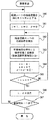
図7は、走行ログデータベース26の構築の流れ(1)を示すフローチャートである。
【0059】
走行ログ収集センタ10では、送受信部21が走行ログを受信すると(ステップ200)、走行ログ処理部24若しくはデータ処理部29が、受信した走行ログから位置と日時を抽出し(ステップ201)、単位走行ログを生成する(ステップ202)。走行ログと単位走行ログについては、3.2節で説明する。
【0060】
続いて、走行ログ処理部24(データ処理部29)は、生成した単位走行ログに提供者属性を付加する(ステップ203)。提供者属性とは、走行ログを提供した提供者の年齢や性別等であるが、その詳細については、3.3節で説明する。
【0061】
次に、走行ログ処理部24(データ処理部29)は、地図データベース25に格納されている地図データを参照して(ステップ204)、最初の結合道路を特定する(ステップ205)。結合道路とは、2つの交差点間を結ぶ1つの道路のことであるが、その詳細については、3.4節で説明する。
【0062】
最初の結合道路を特定すると、走行ログ処理部24(データ処理部29)は、当該結合道路の両端の交差点を特定し(ステップ206)、特定した交差点との距離が一定値以下で最小となる時刻を単位走行ログから特定し(ステップ207)、これを当該交差点の通過時刻とする。なお、最初の結合道路の場合、自動車は、通常、結合道路の途中から移動を開始するため、ステップ206で特定した交差点のいずれか一方のみを通過し、ステップ207では、その一方の交差点の通過時刻を特定する。ただし、最初の結合道路で両端の交差点の両者を通過しているような場合には、通過時刻が遅いほうの交差点とを通過したものとして処理を行う。
【0063】
最初の結合道路の交差点の通過時刻を特定すると(ステップ208でYES)、走行ログ処理部24(データ処理部29)は、当該交差点を共有する結合道路の他端の交差点を特定し(ステップ209)、特定した交差点との距離が一定値以下で最小となる時刻を当該交差点の通過時刻として特定する(ステップ207)。そして、これらの処理を交差点の通過時刻を特定できる限り繰り返し(ステップ208でYES)、通過時刻の特定が不可能となると(ステップ208でNO)、これまでに特定した交差点とその通過時刻のリストを生成する(ステップ210)。通過時刻の特定が不可能となるのは、結合道路の途中で自動車が移動を中止したためである。
【0064】
交差点と通過時刻のリストを生成すると、走行ログ処理部24(データ処理部29)は、当該リストを走行ログデータベース26に格納する(ステップ211)。
【0065】
このステップ203からステップ211の処理は、ステップ202で生成した全ての単位走行ログに対して行い(ステップ212でNO)、全ての単位走行ログに対しての処理が終了すると(ステップ212でYES)、受信した1つの走行ログに対する処理を終了する。
【0066】
図8は、走行ログデータベース26の構築の流れ(2)を示すフローチャートである。
【0067】
走行ログ収集センタ10では、送受信部21が走行ログを受信すると(ステップ220)、走行ログ処理部24若しくはデータ処理部29が、受信した走行ログから位置と日時を抽出し(ステップ221)、単位走行ログを生成する(ステップ222)。
【0068】
続いて、走行ログ処理部24(データ処理部29)は、生成した単位走行ログに提供者属性を付加する(ステップ223)。次に、走行ログ処理部24(データ処理部29)は、地図データベース25に格納されている地図データを参照して(ステップ224)、単位走行ログから最初の結合道路を特定し(ステップ225)、当該結合道路における自動車の進行方向を特定する(ステップ226)。
【0069】
最初の結合道路と進行方向を特定すると、走行ログ処理部24(データ処理部29)は、進行先の交差点との距離が一定値以下で最小となる時刻を単位走行ログから特定し(ステップ227)、これを当該交差点の通過時刻とする。
【0070】
進行先の交差点の通過時刻を特定すると(ステップ228でYES)、走行ログ処理部24(データ処理部29)は、当該交差点の通過後に進入した結合道路を特定し(ステップ229)、特定した結合道路の進行先の交差点との距離が一定値以下で最小となる時刻を当該交差点の通過時刻として特定する(ステップ227)。そして、これらの処理を交差点の通過時刻を特定できる限り繰り返し(ステップ228でYES)、通過時刻の特定が不可能となると(ステップ228でNO)、これまでに特定した交差点とその通過時刻のリストを生成する(ステップ230)。通過時刻の特定が不可能となるのは、結合道路の途中で自動車が移動を中止したためである。
【0071】
交差点と通過時刻のリストを生成すると、走行ログ処理部24(データ処理部29)は、当該リストを走行ログデータベース26に格納する(ステップ231)。
【0072】
このステップ223からステップ231の処理は、ステップ222で生成した全ての単位走行ログに対して行い(ステップ232でNO)、全ての単位走行ログに対しての処理が終了すると(ステップ232でYES)、受信した1つの走行ログに対する処理を終了する。
【0073】
[3.2.走行ログと単位走行ログ]
3.2節では、カーナビゲーションシステム40から収集する走行ログと、その走行ログから生成される単位走行ログについて説明する。
【0074】
図9は、走行ログの一例を示した図である。走行ログは、カーナビゲーションシステム40において、車両の位置を日時とともに、一定時間間隔で記録したものである。図9に示した走行ログでは、車両の位置を経度(東経)と緯度(北緯)で表し、日時を年月日(西暦下2桁+月+日)と時刻(時(24進法表記)+分+秒)で表し、これらをカンマ区切り文字列として記録している。
【0075】
また、走行ログには、車両位置の他に、車両に発生した事象、例えば、エンジンの始動、停止等が記録される。図9に示した走行ログでは、車両に発生した事象としてエンジンの始動(Power on)とエンジンの停止(Power off)が記録されている。なお、カーナビゲーションシステム40は、通常、エンジンが停止している間は電源が遮断されているため、その動作は停止している。カーナビゲーションシステム40は、動作が停止していれば、走行ログの記録を行うことができないため、一定時間以上の記録の中断をエンジンの始動、停止とみなすことで、その記録を省略することもできる。
【0076】
次に、単位走行ログについて説明する。図10は、単位走行ログの一例を示した図である。単位走行ログは、走行ログを車両の1運行を単位として分割したものである。車両の1運行とは、車両のエンジンが始動してカーナビゲーションシステム40の電源が投入されてからエンジンが停止してカーナビゲーションシステム40の電源が遮断されるまでとする。したがって、単位走行ログは、走行ログをエンジンの始動、停止があった時間で分割することにより生成される。
【0077】
[3.3.提供者属性]
3.3節では、単位走行ログ等に付加する提供者属性について説明する。
【0078】
提供者属性とは、走行ログを提供するカーナビの利用者の属性であり、性別や年齢、家族構成、同乗者数、車検証に記載の項目、車両の主用途、趣味等の様々な項目を設定することができる。また、カーナビのメーカー名や機種名を提供者属性として利用するようにしてもよい。これは、後述する結合道路所要時間データベース28を属性毎、即ち、性別や年齢、自動車の種類毎に作成するとき等に利用できる。
【0079】
例えば、性別は、男性・女性の2種類であり、年齢は、直接数字で入力してもよいが、19歳以下、29歳以下、39歳以下、49歳以下、50歳以上のように年齢層を選択させるようにしてもよい。家族構成は、配偶者の有無や子供、乳幼児の数等である。同乗者数は、車両の運行時に同乗していた人の数である。車検証に記載の項目は、自動車の用途、種別、自家用・事業用の区分、車体形状、車名形式、乗車定員、車両重量、車両総重量、原動機の形式、車両の長さ、幅、高さ、総排気量、燃料種別等の全部または一部である。主な用途は、通勤・通学、家族との外出、業務用移動、業務用荷物運搬、業務用乗用等の区別である。
【0080】
これらの項目のうちの大半は、一度設定してカーナビに記憶させておくことができるが、同乗者数等は、都度の入力を行う必要がある。
【0081】
なお、提供者属性の設定に関しては、第5章で説明するプライバシーの保護の観点から、個人を特定できるような情報を避ける場合もある。
【0082】
[3.4.結合道路]
3.4節では、結合道路について説明する。
【0083】
図11は、結合道路を説明するための図である。結合道路は、第1位置としての交差点と第2位置としての交差点の2つの交差点を結ぶ1つの道路であり、原則として結合道路中には交差点は存在しない。例えば、図11に示した道路では、交差点100と交差点101を結ぶ道路が結合道路であり、交差点101と交差点102を結ぶ道路が別の結合道路である。
【0084】
したがって、ある結合道路へ進入した車両は、当該結合道路の他端の交差点から退出することとなる。ただし、結合道路沿いの駐車場等に駐車を行った場合等で、車両が方向を転換した場合には、この限りではない。
【0085】
なお、上述したように、結合道路は途中に交差点を含まないものであるが、極端に幅員の少ない道路との交差点や袋小路となる道路との交差点等、カーナビによるルート探索で無視される可能性のある道路との交差点を含む場合もある。
【0086】
[3.5.交差点通過日時の算出]
3.5節では、交差点通過日時の算出方法について説明する。
【0087】
車両の交差点通過日時を算出する場合には、まず、単位走行ログから対象となる交差点の近傍のデータを抽出する。交差点近傍のデータは、その緯度および経度が交差点の緯度および経度を基準とした一定範囲内となるものや緯度および経度から距離を算出し、算出した距離が対象となる交差点から一定以内のものとなる。
【0088】
単位走行ログから対象となる交差点の近傍のデータを抽出すると、抽出したデータのうち最も交差点に近いデータの日時を当該交差点の通過日時とする。
【0089】
また、カーナビの位置精度が悪い場合や車両が高速で交差点を通過した場合には、最も交差点に近いデータの日時を当該交差点の通過日時とした場合には、数秒の誤差が生じる場合がある。このような場合には、図12に示すように、当該交差点の近傍のデータを関数として、近似式により当該交差点の通過日時を求める。
【0090】
[3.6.誤差の除去]
3.6.節では、走行ログに混入する誤差の除去について説明する。
【0091】
走行ログには、様々な原因により誤差が混入することがある。混入した誤差をそのままにしておけば、当然のことながら交差点通過日時に誤差が生じ、さらには、結合道路所要時間(次節で説明する)にまで誤差が生じてしまう。そのため、走行ログに混入した誤差を除去する必要がある。
【0092】
走行ログに混入する誤差の1つとしては、マップマッチングエラーがある。マップマッチングエラーは、測定した自車位置が実際の位置とずれることにより生じ、交差点等で曲がった際に、地図上の交差点の無い位置で曲がったと解釈されエラーとなるものである。
【0093】
図13は、マップマッチングエラーを説明するための図である。車両が、図13に示すように交差点110を左折し、交差点111および交差点112を直進した後に、図中の破線矢印で示すように交差点113を右折したものとする。このとき、カーナビで自車位置にずれが生じていたとすると、交差点113を右折した際に図中に実線矢印で示すように交差点の無い位置で右折を行った解釈されてエラーとなる。
【0094】
マップマッチングエラーが生じた際には、カーナビは、自車位置の訂正を行うことができるが、これまでに記録していた走行ログを訂正することはできない。そのため、当該走行ログから交差点通過日時を算出する際には、マップマッチングエラーが発生した時に隣接していた交差点から遡って車両が直進を続けた交差点のデータを削除する。例えば、図13に示した例では、交差点113から遡り、交差点110までのデータを削除する。このような処理を行う理由としては、直進を続けていると測定した自車位置がどの時点でずれたのかが判らないためである。
【0095】
このような処理を行うため、カーナビ40では、マップマッチングエラーが発生した際には、その旨を走行ログに記述しておき、後に走行ログ収集センタ10での処理の際に、当該エラーを除去できるようにする。図14は、マップマッチングエラーが発生した際の走行ログの一例を示した図である。同図に示すように、走行ログには、マップマッチングエラーが発生した箇所に「Error」が記述されるている。
【0096】
また、走行ログに混入する誤差の別の原因としては、運転者の意思による車両の駐停車がある。これは、結合道路途中での店舗の立ち寄りや荷物の積み卸し、人待ち等のための駐停車である。
【0097】
車両を駐停車した際に、運転者がエンジンを停止すれば、エンジンの停止が走行ログに記録されるため、単位走行ログを生成する際に駐停車の影響は除去されるが、エンジンを停止しなかった場合には、走行ログは、通常に結合道路を通過した場合と同様となってしまう。
【0098】
そこで、車両の駐停車による誤差の混入を除去するために、車両のパーキングブレーキが使用され、かつ、シートベルトが脱離されたことを走行ログに記録し、単位走行ログを生成する際に当該記録をエンジンの停止があった場合と同様に処理することで、車両の駐停車による誤差の混入を除去することができる。図15は、車両の駐停車があった際の走行ログの一例を示した図である。同図に示すように、走行ログには、車両の駐停車が発生した箇所に「Parking brake + Seat belt」が記述されている。
【0099】
この他にも、ドアの開閉などの車両の状態変化を更に組み合わせることで、より確実に誤差の混入が除去できる。
【0100】
[3.7.結合道路所要時間データベースの構築]
3.7節では、結合道路所要時間データベース28の構築について説明する。結合道路所要時間データベース28は、結合道路を通過するのに要する時間の平均等を格納したものである。ここでは、例として2通りの流れを説明する。
【0101】
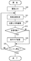
図16は、結合道路所要時間データベース28の構築の流れ(1)を示すフローチャートである。結合道路所要時間データベース28を構築する際には、まず、走行ログデータベース26から条件に適合するデータを抽出する(ステップ240)。条件とは、対象期間と対象地域であり、例えば、対象期間を2000年1月1日から2000年12月31日の1年間とし、対象地域を東京都として設定する。
【0102】
次に、走行ログデータベース26から抽出したデータ、つまり、交差点通過日時リストに基づいて、結合道路毎の通過所要時間を算出する(ステップ241)。所要時間の算出は、結合道路の入口交差点の通過時刻と出口交差点の通過時刻の差により求められる。そして、算出した所要時間毎に出口交差点での進行方向を特定する(ステップ242)。
【0103】
続いて、算出した所要時間毎に、対応する交差点通過日時リストから月、曜日、時を抽出するとともに(ステップ243)、天候データベース32を参照して(ステップ244)、対応する交差点通過日時リストの日時データと結合道路の位置に基づいて天候を特定する(ステップ245)。
【0104】
そして、ステップ241で算出した所要時間を対応する結合道路、出口交差点での進行方向、年、月、曜日、時(時刻)、天候で分類し(ステップ246)、分類毎に所要時間の平均と標準偏差を求め(ステップ247)、結合道路所要時間データベース28に格納する(ステップ248)。
【0105】
つまり、これらの処理は、結合道路とその通過所要時間との関連付け、結合道路と進行方向、年、月、曜日、時(時刻)、天候等の車両の移動時間に変動を与える可能性のある要素との関連付け、これらの結合道路が一致する要素と通過所要時間との関連付け等を行うものである。
【0106】
なお、ステップ246でのデータ分類処理では、必ずしも上述の項目で分類を行う必要はなく、適宜、項目を変更するようにしてもよい。これらの項目は、原則として、車両の移動時間に変動を与える可能性のある要素を示したものであり、これらを適宜変更することで、より適切なデータ分類処理を行うことが可能となる。
【0107】
図17は、結合道路所要時間データベース28の構築の流れ(2)を示すフローチャートである。結合道路所要時間データベース28を構築する際には、まず、走行ログデータベース26から条件に適合するデータを抽出する(ステップ260)。条件とは、対象期間と対象地域であり、例えば、対象期間を2000年1月1日から2000年12月31日の1年間とし、対象地域を東京都として設定する。
【0108】
次に、走行ログデータベース26から抽出したデータ、つまり、交差点通過日時リストに基づいて、結合道路毎の通過所要時間を算出する(ステップ261)。所要時間の算出は、結合道路の入口交差点の通過時刻と出口交差点の通過時刻の差により求められる。そして、算出した所要時間毎に出口交差点での進行方向を特定する(ステップ262)。
【0109】
続いて、算出した所要時間毎に、対応する交差点通過日時リストから月、曜日、時を抽出するとともに(ステップ263)、天候データベース32を参照して(ステップ264)、対応する交差点通過日時リストの日時データと結合道路の位置に基づいて天候を特定する(ステップ265)。
【0110】
次に、地図データベース25を参照して(ステップ266)、道路特徴、地域特徴、周辺施設特徴等を特定する(ステップ267)。道路特徴とは、結合道路の道路としての特徴を示すもので、幅員や車線数、種類(都市間高速道路、都市内高速道路、その他の有料道路、国道、県道、市町村道、その他の幹線道、その他)、制限速度、勾配等により表される。地域特徴とは、結同道路の存在する地域の特徴を示すもので、商業地、住宅地、工業地、山間部、臨海部、春型行楽地、夏型行楽地、秋型行楽地、冬型行楽地、その他の行楽地等により表される。周辺施設特徴とは、結合道路周辺での渋滞の原因となる施設の有無を示すもので、朝夕混雑型施設(駅等)、休日混雑型施設(遊園地等)、午前混雑型施設(病院等)の有無により表される。
【0111】
そして、ステップ261で算出した所要時間を対応する結合道路、出口交差点での進行方向、月、曜日、時、天候で分類し(ステップ268)、分類毎に所要時間の平均と標準偏差を求め(ステップ269)、結合道路所要時間データベース28に格納する(ステップ270)。
【0112】
次に、結合道路所要時間データベース28に格納するデータのフォーマットについて説明する。図18は、結合道路所要時間データベース28に格納するデータのフォーマットの一例を示した図である。
【0113】
同図に示すように、結合所要時間データベース28に格納するデータは、Index120と所要時間の平均121、標準偏差122、進行方向123、出口交差点124、時125、曜日126、月127、天候128により構成される。
【0114】
Index120は、結合道路のシリアルナンバーを示しており、所要時間の平均121は、Index120が示す結合道路における進行方向123、出口交差点124、時125、曜日126、月127、天候128が示す条件での通過所要時間の平均を示している。標準偏差122は、所要時間の平均121の標準偏差である。
【0115】
進行方向123は、車両の進行方向を示すもので、例えば、1が上り、2が下りを示す。出口交差点124は、当該結合道路の出口交差点での車両の進行方向を示すもので、例えば、1が左折等、2が直進等、3が右折等である。ただし、当該交差点が三叉路等の場合には、この限りでは無い。
【0116】
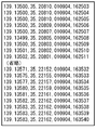
時125は、車両の通過時の時刻のうちの時を示すものであり、曜日126は、車両の通過時の曜日を示すもので、例えば、1が月、2が火、3が水、4が木、5が金、6が土、7が日を示す。月127は、車両の通過時の月を示したものであり、天候128は、車両の通過時の天候を示すもので、例えば、0が快晴、1が晴れ、2がうす曇り、3が曇り、4が小雨、5が雨、6が大雨、7が小雪、8が雪、9が大雪を示している。
【0117】
したがって、「009264,49.9,3.6,1,3,16,2,9,3」で示されるデータは、シリアルナンバーが009264の結合道路を9月の火曜日、16時頃、天候が曇りの条件で、上り方向に進行して右折する場合の通過所要時間の平均が49.9秒となり、その標準偏差が3.6秒となることを示している。
【0118】
なお、ここで示したフォーマットは一例であり、他のフォーマットでデータを構成することもできる。図19は、他のフォーマットの例を示した図である。
【0119】
図19(a)に示す例では、データは、入口交差点位置130と出口交差点位置131、所要時間の平均132、標準偏差133、出口交差点134、時135、曜日136、月137、天候138により構成される。このフォーマットは、入口交差点位置130と出口交差点位置131により結合道路への入口位置と出口位置を特定することで、図18に示したフォーマットのIndex120と進行方向123に代えている。
【0120】
図19(b)に示す例では、データは、Index140と平均速度の平均141、標準偏差142、進行方向143、出口交差点144、時145、曜日146、月147、天候148により構成される。このフォーマットは、結合道路を通過する各車両の通過平均速度を平均した平均速度の平均141を図18に示したフォーマットの所要時間の平均121に代えている。
【0121】
通過平均速度で記録すると、結合道路の長短によるデータ長の変化、つまり、バイト数の変化が生じないといった特徴や、出現頻度が正規分布に近いので統計処理に向いているといった特徴がある。
【0122】
図19(c)に示す例では、データは、Index150と所要時間の平均151、標準偏差152、進行方向153、出口交差点154、時155、曜日156、月157、月の上中下旬158、休日159、五十日160、天候161により構成される。このフォーマットは、日時のうちの日が月の上旬、中旬、下旬のいずれかに相当するかを示す月の上中下旬158と、休日であるか否かを示す休日159、五十日であるか否か示す五十日160を図18に示したフォーマットに加えている。さらに、連休、およびその前日、およびその最終日等の日付の特徴やその結合道路への進入が入口交差点での直進、右折、左折によるものかを付加することもできる。
【0123】
このようなフォーマット、例えば、図19(a)に示したフォーマットにより、結合道路所要時間データベース28へデータを格納すると、結合道路所要時間データベース28の内容は、図20に示すようになる。
【0124】
[4.走行ログの収集]
第4章では、カーナビ40が走行ログを蓄積し、走行ログ収集センタ10へ送信するまでの処理を説明するが、まず、4.1節で走行ログ収集の基本的な処理を説明し、4.2節以降で走行ログ収集の変形例についての説明を行う。
【0125】
[4.1.収集の流れ]
4.1節では、カーナビ40による走行ログ収集の基本的な処理について説明する。ここでは、例として2通りの流れを説明する。
【0126】
図21は、カーナビ40による走行ログ収集の流れ(1)を示すフローチャートである。なお、ここで示す処理の流れは、走行ログ収集センタ10への走行ログの送信を車両が駐車または停車している状態で行う場合(図5(a)、図5(c)、図5(d)等に対応)の例である。
【0127】
カーナビ40は、車両のエンジンが始動されると走行ログの収集を開始するが、最初に、提供者(運転者)に対して提供者属性の入力を促し、入力部53で提供者属性の入力を受け付ける(ステップ300)。続いて、カーナビ40は、自車位置決定部55が車両位置測定部54が測定した車両位置と地図データ51を参照して自車の車両位置を決定し(ステップ301)、走行ログ取得部59が自車位置決定部55が決定した車両位置を取得するとともに日時管理部58が管理している日時を取得して走行ログ蓄積部60に蓄積する(ステップ302)。
【0128】
このステップ301とステップ302の処理は、車両のエンジンが停止されるまで繰り返される(ステップ303でNO)。
【0129】
一方、車両のエンジンが停止されると(ステップ303でYES)、通信部57が走行ログ収集センタ10と通信が可能であれば(ステップ304でYES)、走行ログ処理部61が、走行ログ蓄積部60に現に蓄積した走行ログや過去に蓄積して未送信である走行ログを通信部57を介して走行ログ収集センタ10に送信して(ステップ305)、処理を終了する。
【0130】
また、通信部57が走行ログ収集センタ10との通信が不可能であれば(ステップ304でNO)、走行ログの送信は次回に行うものとして、処理を終了する。
【0131】
図22は、カーナビ40による走行ログ収集の流れ(2)を示すフローチャートである。なお、ここで示す処理の流れは、走行ログ収集センタ10への走行ログの送信を車両が走行している状態で行う場合(図5(a)、図5(d)等に対応)の例である。
【0132】
カーナビ40は、車両のエンジンが始動されると走行ログの収集を開始するが、最初に、提供者(運転者)に対して提供者属性の入力を促し、入力部53で提供者属性の入力を受け付ける(ステップ320)。続いて、カーナビ40は、自車位置決定部55が車両位置測定部54が測定した車両位置と地図データ51を参照して自車の車両位置を決定し(ステップ321)、走行ログ取得部59が自車位置決定部55が決定した車両位置を取得するとともに日時管理部58が管理している日時を取得して走行ログ蓄積部60に蓄積する(ステップ322)。
【0133】
ここで、通信部57が走行ログ収集センタ10との送信が可能で、かつ、走行ログ蓄積部60に過去に蓄積して未送信である走行ログが存在すれば(ステップ323でYES)、走行ログ処理部61が、当該走行ログを通信部57を介して走行ログ収集センタ10に送信する(ステップ324)。
【0134】
また、通信部57による走行ログ収集センタ10との通信が不可能である場合や、送信すべき走行ログが存在しない場合には(ステップ323でNO)、走行ログの送信は行わない。
【0135】
そして、これらの処理を車両のエンジンが停止されるまで繰り返し(ステップ325でNO)、エンジンが停止されると(ステップ325でYES)、カーナビ40は、走行ログの収集処理を終了する。
【0136】
[4.2.走行ログの圧縮]
4.2節では、走行ログの圧縮について説明する。走行ログは、上述したように、車両のエンジンが動作している間、一定の間隔で蓄積される。このため、相当量の走行ログがカーナビ40の走行ログ蓄積部60に蓄積され、走行ログ収集センタ10に送信されることとなるが、走行ログ蓄積部60の容量や走行ログ10との間の通信量を考慮すれば、走行ログは、可能な限り少量であることが望まれる。ここでは、走行ログを圧縮することにより、走行ログの蓄積量や送信量を低減する場合の説明を行う。
【0137】
図23は、走行ログを圧縮する場合の走行ログ収集の流れを示すフローチャートである。なお、ここで示す処理の流れは、図21に示した処理に準じたものであるが、図22に対応した処理(説明は省略する)も可能である。
【0138】
カーナビ40は、車両のエンジンが始動されると走行ログの収集を開始するが、最初に、提供者(運転者)に対して提供者属性の入力を促し、入力部53で提供者属性の入力を受け付ける(ステップ340)。続いて、カーナビ40は、自車位置決定部55が車両位置測定部54が測定した車両位置と地図データ51を参照して自車の車両位置を決定し(ステップ341)、走行ログ取得部59が自車位置決定部55が決定した車両位置を取得するとともに日時管理部58が管理している日時を取得し、これらを圧縮する(ステップ342)。そして、圧縮した走行ログを走行ログ蓄積部60に蓄積する(ステップ343)。なお、走行ログの圧縮方法については、後述する。
【0139】
このステップ341乃至ステップ343の処理は、車両のエンジンが停止されるまで繰り返される(ステップ344でNO)。
【0140】
一方、車両のエンジンが停止されると(ステップ344でYES)、通信部57が走行ログ収集センタ10と通信が可能であれば(ステップ345でYES)、走行ログ処理部61が、走行ログ蓄積部60に現に蓄積した走行ログや過去に蓄積して未送信である走行ログをファイル圧縮し(ステップ346)、通信部57を介して走行ログ収集センタ10に送信して(ステップ347)、処理を終了する。走行ログのファイル圧縮は、コンピュータ間での通信等で通常に用いられているものを利用する。
【0141】
また、通信部57が走行ログ収集センタ10との通信が不可能であれば(ステップ345でNO)、走行ログの送信は次回に行うものとして、処理を終了する。
【0142】
次に、ステップ342における走行ログの圧縮方法について説明するが、ここでは、3通りの圧縮方法について説明する。図24乃至図26は、それぞれ、圧縮した走行ログの例を示した図である。
【0143】
まず、第1の圧縮方法では、走行ログ取得部59は、図24に示すように、車両のエンジンが始動されて走行ログの収集を開始した際に、その時点の日時と以降の走行ログの記録間隔を記録する。そして、以降の走行ログを記録する際には、車両の位置のみを記録する。
【0144】
図24に示す「Power on 010904,162502,1」は、エンジンが始動された際の日時が2001年9月4日16時25分2秒であり、以降、1秒間隔で走行ログを記録することを示している。
【0145】
第2の圧縮方法では、走行ログ取得部59は、図25に示すように、車両のエンジンが始動されて走行ログの収集を開始した際に、その時点での車両の位置と日時、以降の走行ログの記録間隔を記録する。そして、以降は、最初に記録した位置との差分の位置のみを記録する。
【0146】
図25に示す「Power on 139.13500,35.20810,0.00001,010904,162502,1」は、エンジンが始動された際の車両の位置が東経139.13500度、北緯35.20810度、以降に記録する走行ログの差分の乗数が0.00001、日時が2001年9月4日16時25分2秒、以降の記録間隔が1秒で走行ログを記録することを示している。そして、走行ログのうち「0,−1」は、車両の位置が東経139.13500度、北緯35.20809度であることを示している。
【0147】
また、第3の圧縮方法では、走行ログ取得部59は、図26に示すように、車両のエンジンが始動されて走行ログの収集を開始した際に、その時点での車両の位置と日時、以降の走行ログの記録間隔を記録する。そして、以降は、直前に記録した位置との差分の位置のみを記録する。
【0148】
図26に示す「Power on 139.13500,35.20810,0.00001,010904,162502,1」は、エンジンが始動された際の車両の位置が東経139.13500度、北緯35.20810度、以降に記録する走行ログの差分の乗数が0.00001、日時が2001年9月4日16時25分2秒、以降の記録間隔が1秒で走行ログを記録することを示している。そして、走行ログのうち「0,−1」は、直前に「0,0」で示される位置である東経139.13500度、北緯35.20810度から0.00001度分だけ南方に移動した位置である東経139.13500度、北緯35.20809度であることを示している。
【0149】
[4.3.交差点通過日時リストの送信]
4.3節では、カーナビ40が走行ログを交差点通過日時リストに加工して送信する場合について説明する。走行ログは、上述した用に少量で送信することが望ましいが、交差点通過日時リストは、交差点の近傍のデータのみとなるため、走行ログをそのまま送信するよりも通信量が少なくなることが多い。そこで、カーナビ40で交差点通過日時リストへの加工を行った後に走行ログ収集センタ10への送信を行う場合を説明する。
【0150】
図27は、カーナビ40で交差点通過日時リストを生成する場合の走行ログ収集の流れを示すフローチャートである。なお、ここで示す処理の流れは、走行ログの収集を図21に示した処理に準じて行い、走行ログへの加工を図7に示した処理に準じて行うものであるが、図21に示した処理と図8に示した処理、図22に示した処理と図7に示した処理、図22に示した処理と図8に示した処理の組み合わせ等も同様に実行することが可能である。
【0151】
カーナビ40は、車両のエンジンが始動されると走行ログの収集を開始するが、最初に、提供者(運転者)に対して提供者属性の入力を促し、入力部53で提供者属性の入力を受け付ける(ステップ400)。続いて、カーナビ40は、自車位置決定部55が車両位置測定部54が測定した車両位置と地図データ51を参照して自車の車両位置を決定し(ステップ401)、走行ログ取得部59が自車位置決定部55が決定した車両位置を取得するとともに日時管理部58が管理している日時を取得して走行ログ蓄積部60に蓄積する(ステップ402)。
【0152】
このステップ401とステップ402の処理は、車両のエンジンが停止されるまで繰り返される(ステップ403でNO)。
【0153】
一方、車両のエンジンが停止されると(ステップ403でYES)、走行ログ処理部61が、走行ログ蓄積部60に蓄積された走行ログから位置と日時を抽出し(ステップ404)、単位走行ログを生成する(ステップ405)。
【0154】
続いて、走行ログ処理部61は、生成した単位走行ログに、ステップ400で入力された提供者属性を付加し(ステップ406)、地図データ51を参照して(ステップ407)、最初の結合道路を特定する(ステップ408)。
【0155】
最初の結合道路を特定すると、走行ログ処理部61は、当該結合道路の両端の交差点を特定し(ステップ409)、特定した交差点との距離が一定値以下で最小となる時刻を単位走行ログから特定して(ステップ410)、これを当該交差点の通過時刻とする。
【0156】
最初の結合道路の交差点の通過時刻を特定すると(ステップ411でYES)、走行ログ処理部61は、当該交差点を共有する結合道路の他端の交差点を特定し(ステップ412)、特定した交差点との距離が一定値以下で最小となる時刻を当該交差点の通過時刻として特定する(ステップ410)。そして、これらの処理を交差点の通過時刻を特定できる限り繰り返し(ステップ411でYES)、通過時刻の特定が不可能となると(ステップ411でNO)、これまでに特定した交差点とその通過時刻のリストを生成して走行ログ蓄積部60に格納する(ステップ413)。なお、リストを走行ログ蓄積部60に格納する際に、リストに対してファイル圧縮処理を施すようにしてもよい。
【0157】
このステップ406からステップ413の処理は、ステップ405で生成した全ての単位走行ログに対して行う(ステップ414でNO)。
【0158】
そして、全ての単位走行ログに対しての処理が終了すると(ステップ414でYES)、通信部57が走行ログ収集センタ10と通信が可能であれば(ステップ415でYES)、走行ログ処理部61が、走行ログ蓄積部60に蓄積されている交差点通過日時リストを通信部57を介して走行ログ収集センタ10に送信して(ステップ416)、処理を終了する。また、通信部57が走行ログ収集センタ10との通信が不可能であれば(ステップ415でNO)、交差点通過日時リストの送信は次回に行うものとして、処理を終了する。
【0159】
以上は、エンジン停止後に交差点通過日時リストを生成する例を示したが、走行中に交差点通過日時リストを生成するようにしてもよい。
【0160】
なお、走行ログ収集センタ10では、カーナビ40から交差点通過日時リストを受信した場合には、これを走行ログデータベース26に格納し、図7に示した処理若しくは図8に示した処理は行わない。
【0161】
[4.4.結合道路毎の統計処理後の送信]
4.4節では、カーナビ40が走行ログに結合道路毎の所要時間等の統計処理を施して送信する場合について説明する。走行ログは、上述したように少量で送信することが望ましいが、結合道路毎の統計処理結果は、走行ログをそのまま送信するよりも通信量が少なくなることが多い。そこで、カーナビ40で結合道路毎の統計処理を施した後に走行ログ収集センタ10への送信を行う場合を説明する。
【0162】
図28は、カーナビ40で結合道路毎の統計処理を施す場合の走行ログ収集の流れを示すフローチャートである。なお、ここで示す処理の流れは、走行ログの収集を図21に示した処理に準じて行い、結合道路毎の統計処理を図16に示した処理に準じて行うものであるが、図22に示した処理と図16に示した処理の組み合わせ等も同様に実行することが可能である。
【0163】
カーナビ40は、車両のエンジンが始動されると走行ログの収集を開始し、図27で示したステップ400乃至ステップ404の処理と同様の処理を行った後に、単位走行ログを生成する(ステップ420)。そして、図27で示したステップ406乃至ステップ412の処理と同様の処理を行った後に、交差点通過日時リストを生成する(ステップ421)。
【0164】
次に、走行ログ処理部61が交差点通過日時リストに基づいて、結合道路毎の通過所要時間を算出する(ステップ422)。所要時間の算出は、結合道路の入口交差点の通過時刻と出口交差点の通過時刻の差により求められる。そして、算出した所要時間毎に出口交差点での進行方向を特定する(ステップ423)。
【0165】
続いて、走行ログ処理部61は、算出した所要時間毎に、対応する交差点通過日時リストから月、曜日、時を抽出するとともに(ステップ424)、通信部57を介して取得される天候データ若しくは提供者(運転者)により入力される天候データを参照して(ステップ425)、対応する交差点通過日時リストの日時データと結合道路の位置に基づいて天候を特定する(ステップ426)。
【0166】
そして、ステップ422で算出した所要時間を対応する結合道路、出口交差点での進行方向、月、曜日、時、天候で分類し(ステップ427)、分類毎に算出に使ったデータ数と所要時間の平均、標準偏差を求める(ステップ428)。
【0167】
このステップ421(ステップ406乃至ステップ412の処理と同様の処理を含む)からステップ428の処理は、ステップ420で生成した全ての単位走行ログに対して行う(ステップ429でNO)。
【0168】
そして、全ての単位走行ログに対しての処理が終了すると(ステップ429でYES)、通信部57が走行ログ収集センタ10と通信が可能であれば(ステップ430でYES)、走行ログ処理部61が、走行ログ蓄積部60に蓄積されている結合道路毎の統計情報を通信部57を介して走行ログ収集センタ10に送信して(ステップ431)、処理を終了する。また、通信部57が走行ログ収集センタ10との通信が不可能であれば(ステップ430でNO)、結合道路毎の統計情報の送信は次回に行うものとして、処理を終了する。
【0169】
なお、走行ログ収集センタ10では、カーナビ40から結合道路毎の統計情報を受信した場合には、これを結合道路所要時間データベース28に格納し、図16に示した処理は行わない。ただし、結合道路毎の統計情報を格納する際には、結合道路の通過所要時間の平均や標準偏差等を再度算出することとなる。
【0170】
[4.5.結合道路の特徴での統計処理後の送信]
4.5節では、カーナビ40が走行ログに結合道路の特徴で統計処理を施して送信する場合について説明する。結合道路の特徴での統計処理は、4.4節で説明した処理とほぼ同様であるが、最終的に結合道路を特定しないので、第5章で説明する提供者のプライバシーを強固に保護する場合に適している。
【0171】
図29は、カーナビ40で結合道路の特徴での統計処理を施す場合の走行ログ収集の流れを示すフローチャートである。なお、ここで示す処理の流れは、走行ログの収集を図21に示した処理に準じて行い、結合道路毎の統計処理を図17に示した処理に準じて行うものであるが、図22に示した処理と図17に示した処理の組み合わせ等も同様に実行することが可能である。
【0172】
カーナビ40は、車両のエンジンが始動されると走行ログの収集を開始し、図27で示したステップ400乃至ステップ404の処理と同様の処理を行った後に、単位走行ログを生成する(ステップ440)。そして、図27で示したステップ406乃至ステップ412の処理と同様の処理を行った後に、交差点通過日時リストを生成する(ステップ441)。
【0173】
次に、走行ログ処理部61が交差点通過日時リストに基づいて、結合道路毎の通過所要時間を算出する(ステップ442)。所要時間の算出は、結合道路の入口交差点の通過時刻と出口交差点の通過時刻の差により求められる。そして、算出した所要時間毎に出口交差点での進行方向を特定する(ステップ443)。
【0174】
続いて、走行ログ処理部61は、算出した所要時間毎に、対応する交差点通過日時リストから月、曜日、時を抽出するとともに(ステップ444)、通信部57を介して取得される天候データ若しくは提供者(運転者)により入力される天候データを参照して(ステップ445)、対応する交差点通過日時リストの日時データと結合道路の位置に基づいて天候を特定する(ステップ446)。
【0175】
次に、走行ログ処理部61は、地図データ51を参照して(ステップ447)、道路特徴、地域特徴、周辺施設特徴等を特定する(ステップ448)。道路特徴、地域特徴、周辺施設特徴等は、上述した通りである。そして、ステップ442で算出した所要時間を道路特徴、地域特徴、周辺施設特徴、月、曜日、時、天候で分類し(ステップ449)、分類毎に算出に使ったデータ数と所要時間の平均、標準偏差を求める(ステップ450)。
【0176】
このステップ441(ステップ406乃至ステップ412の処理と同様の処理を含む)からステップ450の処理は、ステップ440で生成した全ての単位走行ログに対して行う(ステップ451でNO)。
【0177】
そして、全ての単位走行ログに対しての処理が終了すると(ステップ451でYES)、通信部57が走行ログ収集センタ10と通信が可能であれば(ステップ452でYES)、走行ログ処理部61が、走行ログ蓄積部60に蓄積されている結合道路の特徴での統計情報を通信部57を介して走行ログ収集センタ10に送信して(ステップ453)、処理を終了する。また、通信部57が走行ログ収集センタ10との通信が不可能であれば(ステップ452でNO)、結合道路の特徴での統計情報の送信は次回に行うものとして、処理を終了する。
【0178】
なお、走行ログ収集センタ10では、カーナビ40から結合道路毎の統計情報を受信した場合には、これを結合道路所要時間データベース28に格納し、図17に示した処理は行わない。ただし、結合道路毎の統計情報を格納する際には、結合道路の通過所要時間の平均や標準偏差等を再度算出することとなる。
【0179】
また、この処理により送信された通過所要時間の平均や標準偏差等からは、結合道路を特定することはできないが、図17で説明した処理では、結合道路を特定しているとともに、結合道路の特徴を含むデータを生成しているため、走行ログ収集センタ10では、図17に示した処理で生成したデータに、図29の処理で生成されたデータを結合することで、他のデータと同様の利用を行うことができる。
【0180】
[4.6.パソコンの利用]
4.6節では、カーナビ40が蓄積した走行ログをパソコンを利用して加工し、加工したデータを送信する場合を説明する。この場合、カーナビ40は、単に走行ログを蓄積するのみの処理を行い、カーナビ40により蓄積された走行ログを図5(b)若しくは図5(c)に示した構成によりパソコン(PC43等)で取得して、4.2節で説明した走行ログの圧縮処理、4.3節で説明した交差点通過日時リストの生成処理、4.4節で説明した結合道路毎の統計処理、4.5節で説明した結合道路の特徴での統計処理のいずれかを行って、走行ログ収集センタ10に送信する。
【0181】
なお、パソコンで行う処理は、基本的には、4.2節から4.5節で説明した処理に準じるため、ここでは、交差点通過日時リストを生成する場合の例のみを説明し、他の処理の説明は省略する。
【0182】
図30は、カーナビ40が蓄積した走行ログに基づいて、パソコンを利用して交差点通過日時リストを生成する場合の走行ログ収集の流れを示すフローチャートである。なお、ここで示す処理の流れは、図27で説明した処理に準じているが、他の処理も同様に実行することが可能である。
【0183】
PC43は、カーナビ40から走行ログを取得すると(ステップ460)、取得した走行ログから位置と日時を抽出し(ステップ461)、単位走行ログを生成する(ステップ462)。
【0184】
続いて、PC43は、生成した単位走行ログに、カーナビ40から別途取得した提供者属性を付加し(ステップ462)、地図データ(不図示、PC43内部に保持していてもインターネット12を介して取得しても良い)を参照して(ステップ464)、最初の結合道路を特定する(ステップ465)。
【0185】
最初の結合道路を特定すると、PC43は、当該結合道路の両端の交差点を特定し(ステップ467)、特定した交差点との距離が一定値以下で最小となる時刻を単位走行ログから特定して(ステップ468)、これを当該交差点の通過時刻とする。
【0186】
最初の結合道路の交差点の通過時刻を特定すると(ステップ469でYES)、PC43は、当該交差点を共有する結合道路の他端の交差点を特定し(ステップ470)、特定した交差点との距離が一定値以下で最小となる時刻を当該交差点の通過時刻として特定する(ステップ468)。そして、これらの処理を交差点の通過時刻を特定できる限り繰り返し(ステップ469でYES)、通過時刻の特定が不可能となると(ステップ469でNO)、これまでに特定した交差点とその通過時刻のリストを生成する(ステップ471)。
【0187】
このステップ463からステップ471の処理は、ステップ462で生成した全ての単位走行ログに対して行う(ステップ472でNO)。
【0188】
そして、全ての単位走行ログに対しての処理が終了すると(ステップ472でYES)、PC43は、インターネット12を介して、交差点通過日時リストを走行ログ収集センタ10に送信して(ステップ473)、処理を終了する。
【0189】
なお、走行ログ収集センタ10では、PC43から交差点通過日時リストを受信した場合には、これを走行ログデータベース26に格納し、図7に示した処理若しくは図8に示した処理は行わない。
【0190】
[5.走行ログと提供者]
第5章では、走行ログを提供する提供者に関する処理について説明する。
【0191】
[5.1.プライバシーの保護]
5.1節では、提供者のプライバシーの保護について説明する。これまでに説明してきた走行ログは、高度なプライバシー情報を含んでいる。例えば、走行ログには、提供者の車両が何月何日何時何分何秒にどの位置に存在するかが容易に判明し、さらには、車両の運行中の速度も含むため、速度超過等の法令違反の有無もが判明してしまう。そのため、提供者のプライバシーを徹底して保護しなければ、走行ログの提供者が皆無となってしまう恐れがある。
【0192】
プライバシーの保護においては、走行ログ収集センタ10でのデータ管理はもちろんのこと、インターネット12における情報の漏洩防止に努める必要があるが、インターネット12での漏洩防止には、通信する情報の制限や暗号化処理等を施し、これを提供者に対してホームページ等で明示するようにする。
【0193】
また、走行ログ収集センタ10でのデータ管理は、基本的には、提供者に走行ログ収集センタ10におけるデータ管理を信頼してもらうこととなるが、この他に提供者が送信する走行ログに含まれる情報を制限できるようにしたり、送信した情報を自ら確認できるようにする。
【0194】
[5.2.保護レベルの設定]
5.2節では、提供者のプライバシーの保護レベルの設定について説明する。プライバシーの保護レベルとは、走行ログに含まれる情報の制限レベルであり、提供者が自ら保護レベルを設定することができるようにする。
【0195】
図31乃至33は、それぞれ、カーナビ40の表示部56に表示される保護レベルの設定画面の例を示した図である。図31に示した画面では、提供者に対して走行ログの自動送信の実施を確認する。提供者は、走行ログを制限無く送信するレベルと、情報を制限するレベル、手動送信を行うレベル、送信を行わないレベルを選択することができる。
【0196】
提供者が、送信する情報を制限する場合には、カーナビ40の表示部56には、図32(a)に示すような画面が表示される。当該画面では、送信しない情報として、日時の詳細と、1秒ごとの位置情報、通過した交差点の位置情報を1以上選択できるようになっている。ここで、「1秒」は一例であり、0.5秒や2秒等であっても良い。
【0197】
この画面において、例えば、図32(b)に示すように、通過した交差点の位置情報を送信しないように設定した場合には、走行ログは、4.2節で説明した方法で走行ログ収集センタに送信される。
【0198】
また、図32(c)に示すように、1秒ごとの位置情報を送信しないように設定した場合には、走行ログは、4.3節で説明した方法で走行ログ収集センタに送信される。
【0199】
図33(a)に示すように、1秒ごとの位置情報と通過した交差点の位置情報を送信しないように設定した場合には、走行ログは、4.5節で説明した方法で走行ログ収集センタに送信される。
【0200】
図33(b)に示すように、日時の詳細を送信しないように設定した場合には、走行ログは、4.4節で説明した方法で走行ログ収集センタに送信される。
【0201】
さらに、図33(c)に示すように、日時の詳細と1秒ごとの位置情報、通過した交差点の位置情報を送信しないように設定した場合には、走行ログは、4.5節で説明した方法で走行ログ収集センタに送信される。
【0202】
なお、ここに示した設定は一例であり、この他にも、日付は送信不可能であるが時刻は送信可能とする設定(どこに、いつ、行ったかを特定されたくない場合)等も行うことができる。
【0203】
[5.3.利益供与]
5.3節では、提供者に対する利益供与について説明する。上述したようにプライバシーの保護を徹底した場合であっても、提供者が自らの利益にならないのであれば、通常、通信費をかけてまで走行ログを提供することは、考えられない。このため、提供者に対しては、何らかの利益を供与する。なお、利益の供与は、提供者情報データベース22に格納された提供者の走行ログの提供状況に基づいて行うが、この場合にもプライバシーの保護を徹底する必要があるのは、言うまでもない。
【0204】
提供者に供与する利益としては、単純に、金銭若しくはこれに相当するものが考えられる。また、提供者は、カーナビを利用するユーザでもあるため、供与する利益として、収集した走行ログに基づいて生成した結合道路所要時間データを提供することが考えられる。結合道路所要時間データは、第6章で説明するように、渋滞等の道路状態を考慮したルート探索に用いることができるので、提供者にとっても有用なものである。このとき、提供者には、自らが提供した走行ログを含む地域の結合道路所要時間データを提供するようにしてもよい。
【0205】
また、結合道路所要時間データと組み合わせて利用する不定期イベント予定や天気予報データを提供するようにしてもよい。
【0206】
また、カーナビメーカとの提携により、カーナビ40の地図データ50が更新された際に、更新された地図若しくはその一部を提供者に供与するようにしてもよい。
【0207】
さらに、第7章で説明するWeb向けのルート探索の利用権を提供者に供与することもできる。
【0208】
[6.データのカーナビゲーションシステムでの利用]
第6章では、走行ログ収集センタ10が収集した走行ログや走行ログに基づいて構築した結合道路所要時間データベース28のカーナビゲーションシステムでの利用について説明する。
【0209】
[6.1.カーナビ構成例]
6.1節では、結合道路所要時間データベース28等を利用するカーナビゲーションシステムの構成について説明する。
【0210】
図34は、走行ログを蓄積するカーナビゲーションシステムの構成例を示すブロック図である。同図に示すように、カーナビゲーションシステム70は、地図データ71とルート探索部72、入力部73、車両位置測定部74、自車位置決定部75、表示部76、通信部77、日時管理部78、走行ログ取得部79、走行ログ蓄積部80、走行ログ処理部81、結合道路所要時間データベース82、不定期イベント除外結合道路所要時間データベース83、不定期イベント補正値データベース84を具備して構成される。
【0211】
なお、地図データ71、ルート探索部72、入力部73、車両位置測定部74、自車位置決定部75、表示部76、通信部77、日時管理部78、走行ログ取得部79、走行ログ蓄積部80、走行ログ処理部81は、それぞれ、図6に示したカーナビゲーションシステム40の地図データ51、ルート探索部52、入力部53、車両位置測定部54、自車位置決定部55、表示部56、通信部57、日時管理部58、走行ログ取得部59、走行ログ蓄積部60、走行ログ処理部61に対応する。
【0212】
また、結合道路所要時間データベース82、不定期イベント除外結合道路所要時間データベース83、不定期イベント補正値データベース84は、それぞれ、図4に示した走行ログ収集センタ10に配される結合道路所要時間データベース28、不定期イベント除外結合道路所要時間データベース30、不定期イベント補正値データベース31に格納されるデータの少なくとも一部を格納したものである。
【0213】
この結合道路所要時間データベース82、不定期イベント除外結合道路所要時間データベース83、不定期イベント補正値データベース84は、それぞれ、ルート探索部72によるルート探索時に利用される。次節で説明するルート探索は、結合道路所要時間データベース82だけで可能であるが、この代わりに不定期イベント除外結合道路所要時間データベース83と不定期イベント補正値データベース84を具備することで、より高度なルート検索が可能になる。
【0214】
つまり、結合道路所要時間データベース82、不定期イベント除外結合道路所要時間データベース83、不定期イベント補正値データベース84を用いた場合には、決定された候補ルート毎に通過所要時間に変動を与える可能性のある要因を認識し、この要因に関連付けられた通過所要時間や補正値等を利用して、予測される通過所要時間を算出することができる。
【0215】
[6.2.ルート探索]
6.2節では、カーナビゲーションシステム70でのルート探索について説明する。
【0216】
図35および図36は、カーナビゲーションシステム70におけるルート探索処理の流れを示すフローチャートである。
【0217】
カーナビゲーションシステム70は、入力部73からルート探索の指示があると、ルート探索部72が、自車位置決定部75から車両の現在地を取得する(ステップ500)。そして、提供者により入力部73から目的地が入力されると(ステップ501)、ルート検索を行う(ステップ502)。なお、ここでは、複数のルート候補が探索される。
【0218】
続いて、ルート探索部72は、提供者により入力部72から出発日時が入力されるか、日時管理部78から現在時刻を取得すると(ステップ503)、ステップ502で探索された全候補ルートに対する所要時間の見積を算出する(ステップ504)。この見積の算出については、後述する。
【0219】
ルート探索部72は、全候補ルートの見積を算出すると、当該算出結果に基づいて、推奨ルートとその所要時間(予測)を表示し(ステップ505)、ルート探索処理を終了する。なお、推奨ルートの表示に際しては、例えば、平均所要時間が最小のものと、平均所要時間に標準偏差の2倍の値を加えた時間が最小のもの2ルートを表示する。平均時間が最小のものは、予想される所要時間内での到着確率が50%程度で、平均所要時間に標準偏差の2倍の値を加えた時間が最小のものは、予想される所要時間内での到着確率が96%程度となる。
【0220】
次に、ステップ504での所要時間の見積算出処理について説明する。見積算出処理では、まず、ステップ502で探索された1の候補ルートの結合道路を出発地から目的地の順にR1、R2、・・・Rnと設定する(ステップ520)。そして、変数iを1に、変数tと変数σを0に設定する(ステップ521)。
【0221】
続いて、結合道路Ri、つまり、結合道路R1への到達日時を算出するが、結合道路R1は、出発地からの最初の結合道路となるので、結合道路R1への到達日時は、ステップ503で入力された出発日時とする(ステップ522)。そして、結合道路Riを含む地域の出発日の天候を取得する(ステップ533)。天候の取得は、通信部77によりインターネットを介して行ってもよく、提供者に天気予報に基づく天候を入力させるようにしてもよい。
【0222】
次に、ルート探索部72は、結合道路所要時間データベース82から結合道路Riの曜日や天候等の結合道路所要時間データベース82(結合道路所要時間データベース28)を構築する際に用いた分類項目が該当する所要時間の平均Tと標準偏差Σを検索する(ステップ524)。そして、変数iを1だけインクリメントするとともに、変数tにTの値を加え、変数σの2乗に標準偏差Σの2乗を加える(ステップ525)。曜日や天候等は、車両が移動する際の所要時間に変動を与える要素であるため、これを考慮することでより適切な所要時間を求めることができる。
【0223】
続いて、変数iがn+1でなければ(ステップ526でNO)、ステップ522に戻り、結合道路Ri、つまり、結合道路R2への到達日時を算出する(ステップ522)。到達日時の算出は、出発日時の値に変数tの値を加えたものとなる。
【0224】
そして、このステップ522乃至525の処理を変数iがn+1となるまで、つまり、目的地近傍の結合道路Rnに対する処理が終了するまで繰り返し(ステップ526でNO)、変数iがn+1となると(ステップ526でYES)、変数tと変数σの値を出力する(ステップ527)。
【0225】
これらの処理により、1の候補ルートに対する見積算出処理が終了したので、続いて、別の候補ルートに対する見積算出処理を行い(ステップ528でNO)、全候補ルートに対する見積算出処理を終了すると(ステップ528でYES)、ステップ504の見積算出処理を終了する。
【0226】
[6.3.天候毎のルート探索]
6.2節では、カーナビゲーションシステム70で出発日の天候を取得してルート探索を行ったが、6.3節では、天候を取得することなく、全ての天候のルート探索を行って表示する場合について説明する。
【0227】
図37および図38は、カーナビゲーションシステム70における天候毎のルート探索処理の流れを示すフローチャートである。
【0228】
カーナビゲーションシステム70は、入力部73からルート探索の指示があると、ルート探索部72が、自車位置決定部75から車両の現在地を取得する(ステップ540)。そして、提供者により入力部73から目的地が入力されると(ステップ541)、ルート検索を行う(ステップ542)。なお、ここでは、複数のルート候補が探索される。
【0229】
続いて、ルート探索部72は、提供者により入力部72から出発日時が入力されるか、日時管理部78から現在時刻を取得すると(ステップ543)、見積算出を行うべき天候を決定し(ステップ544)、決定した天候でステップ542で探索された全候補ルートに対する所要時間の見積を算出する(ステップ545)。この見積の算出については、後述する。
【0230】
ルート探索部72は、全候補ルートの見積算出処理を全天候に対して行い(ステップ546でNO)、全天候に対して見積算出処理が終了すると(ステップ546でYES)、当該算出結果に基づいて、推奨ルートとその所要時間(予測)を表示し(ステップ547)、ルート探索処理を終了する。なお、推奨ルートの表示に際しては、例えば、平均所要時間が最小のものと、平均所要時間に標準偏差の2倍の値を加えた時間が最小のもの2ルートを表示する。
【0231】
次に、ステップ545での所要時間の見積算出処理について説明する。見積算出処理では、まず、ステップ542で探索された1の候補ルートの結合道路を出発地から目的地の順にR1、R2、・・・Rnと設定する(ステップ560)。そして、変数iを1に、変数tと変数σを0に設定する(ステップ561)。
【0232】
続いて、結合道路Ri、つまり、結合道路R1への到達日時を算出するが、結合道路R1は、出発地からの最初の結合道路となるので、結合道路R1への到達日時は、ステップ543で入力された出発日時とする(ステップ562)。
【0233】
次に、ルート探索部72は、結合道路所要時間データベース82から結合道路Riの出発日およびステップ544で決定された天候が該当する所要時間の平均Tと標準偏差Σを検索する(ステップ563)。そして、変数iを1だけインクリメントするとともに、変数tにTの値を加え、変数σの2乗に標準偏差Σの2乗を加える(ステップ564)。
【0234】
続いて、変数iがn+1でなければ(ステップ565でNO)、ステップ562に戻り、結合道路Ri、つまり、結合道路R2への到達日時を算出する(ステップ562)。到達日時の算出は、出発日時の値に変数tの値を加えたものとなる。
【0235】
そして、このステップ562乃至564の処理を変数iがn+1となるまで、つまり、目的地近傍の結合道路Rnに対する処理が終了するまで繰り返し(ステップ565でNO)、変数iがn+1となると(ステップ565でYES)、変数tと変数σの値を出力する(ステップ566)。
【0236】
これらの処理により、1の候補ルートに対する見積算出処理が終了したので、続いて、別の候補ルートに対する見積算出処理を行い(ステップ567でNO)、全候補ルートに対する見積算出処理を終了すると(ステップ567でYES)、ステップ545の見積算出処理を終了する。
【0237】
[6.4.不定期イベントを考慮したルート探索]
6.2節および6.3節では、カーナビゲーションシステム70で不定期イベントを考慮しない、つまり、不定期イベント除外結合道路所要時間データベース83と不定期イベント補正値データベース84を利用しないルート探索を行う場合を説明したが、6.4節では、不定期イベント除外結合道路所要時間データベース83と不定期イベント補正値データベース84を利用したルート検索について説明する。
【0238】
まず、不定期イベント除外結合道路所要時間データベース83について説明するが、不定期イベント除外結合道路所要時間データベース83は、走行ログ収集センタ10に配される不定期イベント除外結合道路所要時間データベース30のデータの少なくとも一部を格納したものであるため、不定期イベント除外結合道路所要時間データベース30の構築処理について説明する。
【0239】
図39は、不定期イベント除外結合道路所要時間データベース30の構築処理の流れを示すフローチャートである。不定期イベント除外結合道路所要時間データベース30を構築する際には、まず、データ処理部29が走行ログデータベース26から条件に適合するデータを抽出する(ステップ600)。条件とは、対象期間と対象地域であり、例えば、対象期間を2000年1月1日から2000年12月31日の1年間とし、対象地域を東京都として設定する。
【0240】
次に、データ処理部29は、不定期イベントデータベース33を参照して、対象期間内における不定期イベントの発生日時を取得し(ステップ601)、抽出した走行ログから不定期イベントに影響される日時分を除外する(ステップ602)。
【0241】
そして、データ処理部29は、不定期イベントに影響される日時分を除外したデータ、つまり、不定期イベントに影響される日時分を除外した交差点通過日時リストに基づいて、結合道路毎の通過所要時間を算出する(ステップ603)。所要時間の算出は、結合道路の入口交差点の通過時刻と出口交差点の通過時刻の差により求められる。そして、算出した所要時間毎に出口交差点での進行方向を特定する(ステップ604)。
【0242】
続いて、算出した所要時間毎に、対応する交差点通過日時リストから月、曜日、時を抽出するとともに(ステップ605)、天候データベース32を参照して(ステップ606)、対応する交差点通過日時リストの日時データと結合道路の位置に基づいて天候を特定する(ステップ607)。
【0243】
そして、ステップ603で算出した所要時間を対応する結合道路、出口交差点での進行方向、月、曜日、時、天候で分類し(ステップ608)、分類毎に所要時間の平均と標準偏差を求め(ステップ609)、結合道路所要時間データベース28に格納する(ステップ610)。
【0244】
次に、不定期イベント補正値データベース84について説明するが、不定期イベント補正値データベース84は、走行ログ収集センタ10に配される不定期イベント補正値データベース31のデータの少なくとも一部を格納したものであるため、不定期イベント補正値データベース31の構築処理について説明する。
【0245】
図40は、不定期イベント補正値データベース31の構築処理の流れを示すフローチャートである。不定期イベント補正値データベース31を構築する際には、まず、データ処理部29が結合道路所要時間データベース28から条件に適合する不定期イベントが開催された日のデータを抽出する(ステップ620)。条件とは、対対象期間と対象地域であり、ここで抽出したデータを情報(A)とする。
【0246】
次に、データ処理部29は、不定期イベント除外結合道路所要時間データベース30から条件に適合するデータを抽出する(ステップ621)。そして、ここで抽出したデータを情報(B)とする。
【0247】
続いて、データ処理部29は、情報(A)と情報(B)の差若しくは比をデータの分類毎に算出し(ステップ622)、算出した差若しくは比を不定期イベントの補正値として、不定期イベント補正値データベース31へ格納し(ステップ623)、処理を終了する。
【0248】
次に、不定期イベント除外結合道路所要時間データベース83と不定期イベント補正値データベース84を利用したルート検索について説明する。
【0249】
不定期イベント除外結合道路所要時間データベース83と不定期イベント補正値データベース84を利用したルート検索処理は、基本的には、図35に示した処理の流れと同様であり、この処理のうち、ステップ504での見積算出処理のみが異なるため、ここでは、見積算出処理の流れのみを説明する。
【0250】
図41は、不定期イベント除外結合道路所要時間データベース83と不定期イベント補正値データベース84を利用したルート検索処理における見積算出処理の流れを示したフローチャートである。
【0251】
見積算出処理では、まず、ステップ502で探索された1の候補ルートの結合道路を出発地から目的地の順にR1、R2、・・・Rnと設定する(ステップ640)。そして、変数iを1に、変数tと変数σを0に設定する(ステップ641)。
【0252】
続いて、結合道路Ri、つまり、結合道路R1への到達日時を算出するが、結合道路R1は、出発地からの最初の結合道路となるので、結合道路R1への到達日時は、ステップ503で入力された出発日時とする(ステップ642)。そして、結合道路Riを含む地域の出発日の天候を取得する(ステップ643)。天候の取得は、通信部77によりインターネットを介して行ってもよく、提供者に天気予報に基づく天候を入力させるようにしてもよい。
【0253】
次に、ルート探索部72は、不定期イベント除外結合道路所要時間データベース83から結合道路Riの曜日や天候等の結合道路所要時間データベース82(結合道路所要時間データベース28)を構築する際に用いた分類項目が該当する所要時間の平均Tと標準偏差Σを検索する(ステップ644)。そして、結合道路Riを含む地域のイベント情報を取得する(ステップ645)。イベント情報の取得は、通信部77によりインターネットを介して行ってもよく、提供者に入力させるようにしてもよい。
【0254】
イベント情報を取得した結果、出発日の結合道路Riに影響が生じるイベントが存在した場合には(ステップ646でYES)、不定期イベント補正値データベース84を検索して、当該結合道路の該当する不定期イベントの補正値を取得し、ステップ644で検索した所要時間の平均Tと標準偏差Σを補正する(ステップ647)。補正処理は、補正値が上述の情報(A)と情報(B)の差である場合には、補正値の加算処理を行い、補正値が上述の情報(A)と情報(B)の比である場合には、補正値の乗算処理を行う。
【0255】
一方、出発日の結合道路Riに影響が生じるイベントが存在しない場合には(ステップ646でNO)、所要時間の平均Tと標準偏差Σの補正は行わない。
【0256】
そして、変数iを1だけインクリメントするとともに、変数tにT若しくは補正したTの値を加え、変数σの2乗に標準偏差Σ若しくは補正したΣの2乗を加える(ステップ648)。
【0257】
続いて、変数iがn+1でなければ(ステップ649でNO)、ステップ642に戻り、結合道路Ri、つまり、結合道路R2への到達日時を算出する(ステップ642)。到達日時の算出は、出発日時の値に変数tの値を加えたものとなる。
【0258】
そして、このステップ642乃至648の処理を変数iがn+1となるまで、つまり、目的地近傍の結合道路Rnに対する処理が終了するまで繰り返し(ステップ649でNO)、変数iがn+1となると(ステップ649でYES)、変数tと変数σの値を出力する(ステップ650)。
【0259】
これらの処理により、1の候補ルートに対する見積算出処理が終了したので、続いて、別の候補ルートに対する見積算出処理を行い(ステップ651でNO)、全候補ルートに対する見積算出処理を終了すると(ステップ651でYES)、ステップ504の見積算出処理に相当する不定期イベント除外結合道路所要時間データベース83と不定期イベント補正値データベース84を利用したルート検索処理における見積算出処理を終了する。
【0260】
[6.5.到着日時指定ルート探索]
6.5節では、カーナビゲーションシステム70での到着日時指定ルート探索について説明する。
【0261】
図42および図43は、カーナビゲーションシステム70における到着日時指定ルート探索処理の流れを示すフローチャートである。
【0262】
カーナビゲーションシステム70は、入力部73からルート探索の指示があると、ルート探索部72が、自車位置決定部75から車両の現在地を取得する(ステップ660)。そして、提供者により入力部73から目的地が入力されると(ステップ661)、ルート検索を行う(ステップ662)。なお、ここでは、複数のルート候補が探索される。
【0263】
続いて、ルート探索部72は、提供者により入力部72から到着希望日時が入力されと(ステップ663)、ステップ662で探索された全候補ルートに対する所要時間の見積を算出する(ステップ664)。この見積の算出については、後述する。
【0264】
ルート探索部72は、全候補ルートの見積を算出すると、当該算出結果に基づいて、推奨ルートとその所要時間(予測)を表示し(ステップ665)、ルート探索処理を終了する。なお、推奨ルートの表示に際しては、例えば、平均所要時間が最小のものと、平均所要時間に標準偏差の2倍の値を加えた時間が最小のもの2ルートを表示する。
【0265】
次に、ステップ664での所要時間の見積算出処理について説明する。見積算出処理では、まず、ステップ662で探索された1の候補ルートの結合道路を出発地から目的地の順にR1、R2、・・・Rnと設定する(ステップ680)。そして、変数iをnに、変数tと変数σを0に設定する(ステップ681)。
【0266】
続いて、結合道路Ri、つまり、結合道路Rnへの到達日時を算出するが、結合道路Rnは、目的地に最近傍の結合道路となるので、結合道路Rnへの到達日時は、ステップ663で入力された希望到着日時とする(ステップ682)。そして、結合道路Riを含む地域の出発日の天候を取得する(ステップ683)。天候の取得は、通信部77によりインターネットを介して行ってもよく、提供者に天気予報に基づく天候を入力させるようにしてもよい。
【0267】
次に、ルート探索部72は、不定期イベント除外結合道路所要時間データベース83から結合道路Riの曜日や天候等の結合道路所要時間データベース82(結合道路所要時間データベース28)を構築する際に用いた分類項目が該当する所要時間の平均Tと標準偏差Σを検索する(ステップ684)。そして、結合道路Riを含む地域のイベント情報を取得する(ステップ685)。イベント情報の取得は、通信部77によりインターネットを介して行ってもよく、提供者に入力させるようにしてもよい。
【0268】
イベント情報を取得した結果、出発日の結合道路Riに影響が生じるイベントが存在した場合には(ステップ686でYES)、不定期イベント補正値データベース84を検索して、当該結合道路の該当する不定期イベントの補正値を取得し、ステップ684で検索した所要時間の平均Tと標準偏差Σを補正する(ステップ687)。補正処理は、補正値が上述の情報(A)と情報(B)の差である場合には、補正値の加算処理を行い、補正値が上述の情報(A)と情報(B)の比である場合には、補正値の乗算処理を行う。
【0269】
一方、出発日の結合道路Riに影響が生じるイベントが存在しない場合には(ステップ686でNO)、所要時間の平均Tと標準偏差Σの補正は行わない。
【0270】
そして、変数iを1だけデクリメントするとともに、変数tにT若しくは補正したTの値を加え、変数σの2乗に標準偏差Σ若しくは補正したΣの2乗を加える(ステップ688)。
【0271】
続いて、変数iが0でなければ(ステップ689でNO)、ステップ682に戻り、結合道路Ri、つまり、結合道路R(n−1)への到達日時を算出する(ステップ682)。到達日時の算出は、出発日時の値に変数tの値を加えたものとなる。
【0272】
そして、このステップ682乃至688の処理を変数iが0となるまで、つまり、出発地近傍の結合道路R1に対する処理が終了するまで繰り返し(ステップ689でNO)、変数iが0となると(ステップ689でYES)、変数tと変数σの値を出力する(ステップ690)。
【0273】
これらの処理により、1の候補ルートに対する見積算出処理が終了したので、続いて、別の候補ルートに対する見積算出処理を行い(ステップ691でNO)、全候補ルートに対する見積算出処理を終了すると(ステップ691でYES)、ステップ664の見積算出処理を終了する。
【0274】
なお、ここでは、不定期イベント除外結合道路所要時間データベース83と不定期イベント補正値データベース84を利用した場合を説明したが、結合道路所要時間データベース82のみを利用した処理も可能である。ただし、当該処理は、図35および図36に示した処理と図42および図43に示した処理とから類推できると考えられるので、その説明は、省略する。
【0275】
[7.走行ログデータベースの他の利用例]
第7章では、走行ログデータベース26や結合道路所要時間データベース28等のカーナビゲーションシステム以外への利用例について説明する。
【0276】
[7.1.Web向けルート探索]
7.1節では、Web向けのルート検索について説明する。Web向けのルート検索とは、インターネット12を利用して、PC等のWebクライアントでカーナビゲーションシステムと同様のルート検索を行えるようにしたサービスを提供するものである。このサービスの提供は、Webサーバにより行われ、当該Webサーバが上述のカーナビゲーションシステム70と同様に動作し、ルート検索を行う。なお、Webサーバでの処理は、上述の説明から類推できると考えられるため、ここでの説明は、省略する。
【0277】
[7.2.渋滞予報]
7.2節では、渋滞予報について説明する。走行ログ収集センタ10では、様々な車両から収集した走行ログに基づくいて構築した結合道路所要時間データベース28を有している。この結合道路所要時間データベース28は、各結合道路での所要時間等を時刻や曜日、天候等の渋滞量に影響する要因で分類したデータを管理しているため、これらを利用することで渋滞の予想が可能となり、渋滞予報をサービスとして提供することができる。
【0278】
[7.3.道路交通統計]
7.3節では、道路交通統計への利用について説明する。
【0279】
図44は、走行ログの道路交通統計への利用を説明するための図である。道路交通統計において、図44(a)に示すような交差点170と交差点171の間の着目点172での道路交通量を取得したいとする。この場合には、図44(b)に示すような交差点180と交差点181の間に測定器設置点182が存在する道路を着目点172の近傍で条件が似通ったから探し、以下に説明する処理を実行することで、着目点172の道路交通量を推定することができる。
【0280】
図45は、着目点172における道路交通量推定処理の流れを示すフローチャートである。
【0281】
道路交通量推定処理では、まず、着目点172と日時等の条件を指定する(ステップ700)。続いて、着目点172を含む結合道路を特定する(ステップ701)。次に、交差点通過日時リストから入口交差点である交差点170を通過した車両のデータを抽出する(ステップ702)。そして、抽出したデータを日時等の指定条件で絞り込み(ステップ703)、さらに進行方向が交差点171方向であるデータへの絞り込みを行う(ステップ704)。そして、絞り込みを行った結果のデータ数をN1とする(ステップ705)。
【0282】
次に、測定器設置点182を含む参考結合道路を特定する(ステップ706)。同様に、交差点通過日時リストから入口交差点である交差点180を通過した車両のデータを抽出する(ステップ707)。そして、抽出したデータを日時等の指定条件で絞り込み(ステップ708)、さらに進行方向が交差点181方向であるデータへの絞り込みを行う(ステップ709)。そして、絞り込みを行った結果のデータ数をN2とする(ステップ710)。
【0283】
続いて、測定器設置点182に設置された測定器により測定された交通量N3を取得し(ステップ711)、(N1/N2)×N3により着目点172の推定交通量を算出する。なお、(N1/N2)×N3は、N1/(N2/N3)と表すことができるが、N2/N3は、走行ログの収集対象となるカーナビの普及率である。
【0284】
[7.4.コンサルティング]
7.4節では、コンサルティングサービスへの利用について説明する。走行ログ収集センタ10では、走行ログを収集する際に、提供者属性を併せて収集している。このため、各結合道路毎に、7.3節で示した処理を提供者属性毎に分けて実施することで、どのような目的の車両がどの位の量通過するかが判る。このため、これらのデータを店舗の出店計画等のコンサルティングに利用することができる。
【0285】
【発明の効果】
以上説明したように、本発明によれば、移動体が移動する移動時間に変動を与えた可能性を有する変動要因毎に実際の移動時間を分類したので、変動要因に基づいて将来の移動時間をより正確に予測することが可能となる。
【図面の簡単な説明】
【図1】走行データ処理システムの概要を示した図である。
【図2】走行データ処理システムの概略構成を示した図である。
【図3】走行ログ収集センタ10の構成例を示したブロック図である。
【図4】走行ログ収集センタ10の別の構成例を示したブロック図である。
【図5】走行ログを収集するための構成例を示した図である。
【図6】走行ログを蓄積するカーナビゲーションシステムの構成例を示すブロック図である。
【図7】走行ログデータベース26の構築の流れ(1)を示すフローチャートである。
【図8】走行ログデータベース26の構築の流れ(2)を示すフローチャートである。
【図9】走行ログの一例を示した図である。
【図10】単位走行ログの一例を示した図である。
【図11】結合道路を説明するための図である。
【図12】交差点通過日時の算出方法を説明するための図である。
【図13】マップマッチングエラーを説明するための図である。
【図14】マップマッチングエラーが発生した際の走行ログの一例を示した図である。
【図15】車両の駐停車があった際の走行ログの一例を示した図である。
【図16】結合道路所要時間データベース28の構築の流れ(1)を示すフローチャートである。
【図17】結合道路所要時間データベース28の構築の流れ(2)を示すフローチャートである。
【図18】結合道路所要時間データベース28に格納するデータのフォーマットの一例を示した図である。
【図19】結合道路所要時間データベース28に格納するデータのフォーマットの他の例を示した図である。
【図20】結合道路所要時間データベース28の内容の例を示した図である。
【図21】カーナビ40による走行ログ収集の流れ(1)を示すフローチャートである。
【図22】カーナビ40による走行ログ収集の流れ(2)を示すフローチャートである。
【図23】走行ログを圧縮する場合の走行ログ収集の流れを示すフローチャートである。
【図24】圧縮した走行ログの例を示した図(1)である。
【図25】圧縮した走行ログの例を示した図(2)である。
【図26】圧縮した走行ログの例を示した図(3)である。
【図27】カーナビ40で交差点通過日時リストを生成する場合の走行ログ収集の流れを示すフローチャートである。
【図28】カーナビ40で結合道路毎の統計処理を施す場合の走行ログ収集の流れを示すフローチャートである。
【図29】カーナビ40で結合道路の特徴での統計処理を施す場合の走行ログ収集の流れを示すフローチャートである。
【図30】カーナビ40が蓄積した走行ログに基づいて、パソコンを利用して交差点通過日時リストを生成する場合の走行ログ収集の流れを示すフローチャートである。
【図31】カーナビ40の表示部56に表示される保護レベルの設定画面の例を示した図(1)である。
【図32】カーナビ40の表示部56に表示される保護レベルの設定画面の例を示した図(2)である。
【図33】カーナビ40の表示部56に表示される保護レベルの設定画面の例を示した図(3)である。
【図34】走行ログを蓄積するカーナビゲーションシステムの構成例を示すブロック図である。
【図35】カーナビゲーションシステム70におけるルート探索処理の流れを示すフローチャート(1)である。
【図36】カーナビゲーションシステム70におけるルート探索処理の流れを示すフローチャート(2)である。
【図37】カーナビゲーションシステム70における天候毎のルート探索処理の流れを示すフローチャート(1)である。
【図38】カーナビゲーションシステム70における天候毎のルート探索処理の流れを示すフローチャート(2)である。
【図39】不定期イベント除外結合道路所要時間データベース30の構築処理の流れを示すフローチャートである。
【図40】不定期イベント補正値データベース31の構築処理の流れを示すフローチャートである。
【図41】不定期イベント除外結合道路所要時間データベース83と不定期イベント補正値データベース84を利用したルート検索処理における見積算出処理の流れを示したフローチャートである。
【図42】カーナビゲーションシステム70における到着日時指定ルート探索処理の流れを示すフローチャート(1)である。
【図43】カーナビゲーションシステム70における到着日時指定ルート探索処理の流れを示すフローチャート(2)である。
【図44】走行ログの道路交通統計への利用を説明するための図である。
【図45】着目点172における道路交通量推定処理の流れを示すフローチャートである。
【符号の説明】
1 走行ログ収集
2 コンテンツ事業
3 カーナビユーザ
4 カーナビメーカ
5 Webサービス
6 データベース販売
7 渋滞予報配信
8 道路交通統計
9 店舗出店計画
10 走行ログ収集センタ
11−1〜11−n カーナビ搭載車
12 インターンネット
21 送受信部
22 提供者情報データベース
23 走行ログ取得部
24 走行ログ処理部
25 地図データベース
26 走行ログデータベース
27 走行ログ加工部
28 結合道路所要時間データベース
29 データ処理部
30 不定期イベント除外結合道路所要時間データベース
31 不定期イベント補正値データベース
32 天候データベース
33 不定期イベントデータベース
40、40−1〜40−3 カーナビゲーションシステム
41 携帯電話
42 メモリカード
43 PC
44 LANアダプタ
45 宅内アクセスポイント
46 街頭アクセスポイント
51 地図データ
52 ルート探索部
53 入力部
54 車両位置測定部
55 自車位置決定部
56 表示部
57 通信部
58 日時管理部
59 走行ログ取得部
60 走行ログ蓄積部
61 走行ログ処理部
70 カーナビゲーションシステム
71 地図データ
72 ルート探索部
73 入力部
74 車両位置測定部
75 自車位置決定部
76 表示部
77 通信部
78 日時管理部
79 走行ログ取得部
80 走行ログ蓄積部
81 走行ログ処理部
82 結合道路所要時間データベース
83 不定期イベント除外結合道路所要時間データベース
84 不定期イベント補正値データベース
100 交差点
101 交差点
102 交差点
110 交差点
111 交差点
112 交差点
113 交差点
120 Index
121 所要時間の平均
122 標準偏差
123 進行方向
124 出口交差点
125 時
126 曜日
127 月
128 天候
130 入口交差点位置
131 出口交差点位置
132 所要時間の平均
133 標準偏差
134 出口交差点
135 時
136 曜日
137 月
138 天候
140 Index
141 平均速度の平均
142 標準偏差
143 進行方向
144 出口交差点
145 時
146 曜日
147 月
148 天候
150 Index
151 所要時間の平均
152 標準偏差
153 進行方向
154 出口交差点
155 時
156 曜日
157 月
158 月の上中下旬
159 休日
160 五十日
161 天候
170 交差点
171 交差点
172 着目点
180 交差点
181 交差点
182 測定器設置点[0001]
BACKGROUND OF THE INVENTION
The present invention relates to a movement information classification device, a movement information classification method, and a movement information classification program, and in particular, a movement information classification apparatus, a movement information classification method, and the like that efficiently classify movement information such as a movement position and movement time of a moving object, And a movement information classification program.
[0002]
[Prior art]
In recent years, car navigation systems have become widespread. The car navigation system searches for a route to a destination by referring to map data or the like, and measures the position of the vehicle using GPS (Global Positioning System) or the like and displays it on a map.
[0003]
Also, in recent car navigation systems, FM traffic etc. are received to acquire road traffic jam information, etc., route search avoiding traffic jam locations, and measured vehicle position is stored in time series as travel trajectory data In addition, there are some that can check the traveling locus of the vehicle.
[0004]
In addition, there are various techniques for collecting movement information of vehicles and the like (see, for example,
[Patent Document 1]
Japanese Patent Laid-Open No. 10-11688
[Patent Document 2]
Japanese Patent Laid-Open No. 11-245853
[0005]
[Problems to be solved by the invention]
As described above, many techniques for collecting movement information of a moving body such as a vehicle such as a car navigation system have been proposed. However, the collected movement information is often an enormous amount and the amount of information is large, but there are cases where it is difficult to use these efficiently and effectively.
[0006]
Accordingly, the present invention provides a movement information classification device, a movement information classification method, and a movement information classification program that can classify movement information related to movement of a moving body such as a vehicle so as to be used effectively and efficiently. For the purpose.
[0007]
[Means for Solving the Problems]
In order to achieve the above-described object, the invention according to
[0008]
The invention of claim 2The invention according to
[0009]
The invention of claim 3The moving time specifying information for specifying the time required for the moving body to move the moving position connecting the two predetermined points and the time when the moving body moved the moving position are specified. An irregular event that has acquired the moving time specifying information and the moving position specifying information for specifying the moving position, and has been generated outside the moving body, and has the possibility of giving fluctuation to the moving time for the moving body to move the moving position. As a fluctuation factor, obtain fluctuation factor information indicating the fluctuation factor, factor occurrence position specifying information for specifying the position where the fluctuation factor has occurred, and time specifying information for specifying the time when the fluctuation factor has occurred, The movement position specified by the movement position specification information corresponds to the position specified by the factor occurrence position specification information, and is specified by the time specified by the movement time specification information and the time specification information. The movement time identification information and the fluctuation factor information corresponding to the time to be associated are associated, the movement position that is the target of the movement time is identified, and the movement position is the same as the identified movement position in the movement time identification information. The travel time specifying information obtained by excluding the travel time specifying information associated with the variation factor information from the corresponding travel time specifying information is used as a predicted value of the travel time.
[0010]
The invention of claim 4The moving time specifying information for specifying the time required for the moving body to move the moving position connecting the two predetermined points and the time when the moving body moved the moving position are specified. Possibility that movement information acquisition processing for acquiring movement time specifying information and movement position specifying information for specifying the movement position, and a movement time generated by the moving body moving outside the moving body have been changed. With the occurrence of an irregular event having a variable as a variable factor, variable factor information indicating the variable factor, factor generation position specifying information for specifying the position where the variable factor has occurred, and time specifying information for specifying the time at which the variable factor has occurred According to the fluctuation information acquisition process, the movement position specified by the movement position specification information acquired by the movement information acquisition process, and the factor occurrence position specification information acquired by the fluctuation information acquisition process. Corresponds to the position specified and the time specified by the movement time specifying information acquired by the movement information acquiring process and the time specified by the time specifying information acquired by the variation information acquiring process An associating process for associating the traveling time specifying information and the variation factor information, a moving position specifying process for specifying a moving position to be predicted for the moving time, and the moving time specifying information acquired by the moving information acquiring process. Among them, the moving time specifying information obtained by excluding the moving time specifying information associated with the variation factor information by the association process from the moving time specifying information corresponding to the same moving position as the moving position specified by the moving position specifying process is moved. It is characterized by causing a computer to execute travel time prediction processing used as a predicted time value.
[0019]
DETAILED DESCRIPTION OF THE INVENTION
Hereinafter, an embodiment of a movement information classification device, a movement information classification method, and a movement information classification program according to the present invention will be described in detail with reference to the accompanying drawings. In this description, a table of contents is shown first. The following description will be made along the table of contents.
[0020]
[table of contents]
1. Overview
2. System configuration
2.1. Travel log collection center
2.2. Travel log collection
3. Construction of travel log database
3.1. Construction flow
3.2. Travel log and unit travel log
3.3. Provider attribute
3.4. Combined road
3.5. Calculation of intersection passage date and time
3.6. Error elimination
3.7. Construction of combined road travel time database
4). Travel log collection
4.1. Collection flow
4.2. Travel log compression
4.3. Send intersection crossing date list
4.4. Transmission after statistical processing for each combined road
4.5. Post-statistical transmission on combined road features
4.6. Use of PC
5. Travel log and provider
5.1. Privacy protection
5.2. Setting the protection level
5.3. Benefit
6). Use of data in car navigation systems
6.1. Car navigation configuration example
6.2. Route search
6.3. Route search by weather
6.4. Route search considering irregular events
6.5. Route search with specified arrival date
7. Other usage examples of the travel log database
7.1. Route search for the Web
7.2. Traffic jam forecast
7.3. Road traffic statistics
7.4. consulting
[0021]
[1. Overview]
In
[0022]
FIG. 1 is a diagram showing an outline of a travel data processing system. As shown in the figure, in the travel data processing system, a travel
[0023]
The
[0024]
The
[0025]
For example, information (however, excluding accident traffic jams) for performing route search taking into account traffic jam prediction based on the travel log is provided to the
[0026]
Moreover, since it is possible to estimate the traffic volume and the like of each road from the travel log, this can be used for the
[0027]
[2. System configuration]
[0028]
FIG. 2 is a diagram showing a schematic configuration of the travel data processing system. As shown in the figure, in the travel data processing system, the travel
[0029]
Therefore, the configuration of the travel
[0030]
[2.1. Travel log collection center]
In section 2.1, the configuration of the travel
[0031]
FIG. 3 is a block diagram illustrating a configuration example of the travel
[0032]
The transmission /
[0033]
The travel
[0034]
Based on the travel log stored in the
[0035]
The processing in each part of the travel
[0036]
Incidentally, in the configuration example of the travel
[0037]
FIG. 4 is a block diagram showing another configuration example of the travel
[0038]
The transmission /
[0039]
The
[0040]
The irregular event-excluded combined road required
[0041]
The irregular event
[0042]
The
[0043]
[2.2. Travel log collection]
Section 2.2 describes the configuration for collecting travel logs.
[0044]
FIG. 5 is a diagram illustrating a configuration example for collecting a travel log. First, in the configuration shown in FIG. 5A, the car navigation system 40-1 is connected to the
[0045]
In the configuration shown in FIG. 5B, the car navigation system 40-2 stores the accumulated travel log in a storage medium such as the
[0046]
In the configuration shown in FIG. 5C, the car navigation system 40-3 is connected to a
[0047]
Further, in the configuration shown in FIG. 5D, the car navigation system 40-3 is connected to the
[0048]
Next, the configuration of a car navigation system that accumulates travel logs will be described. FIG. 6 is a block diagram illustrating a configuration example of a car navigation system that accumulates a travel log.
[0049]
As shown in the figure, the
[0050]
The
[0051]
The
[0052]
The
[0053]
The vehicle
[0054]
The
[0055]
The date and
[0056]
[3. Construction of travel log database]
In
[0057]
[3.1. Construction flow]
In Section 3.1, the flow of construction of the
[0058]
FIG. 7 is a flowchart showing a flow (1) of construction of the
[0059]
In the travel
[0060]
Subsequently, the travel log processing unit 24 (data processing unit 29) adds a provider attribute to the generated unit travel log (step 203). The provider attribute is the age, sex, etc. of the provider who provided the travel log, and details thereof will be described in Section 3.3.
[0061]
Next, the travel log processing unit 24 (data processing unit 29) refers to the map data stored in the map database 25 (step 204) and identifies the first combined road (step 205). The combined road is one road that connects two intersections, and details thereof will be described in section 3.4.
[0062]
When the first combined road is specified, the travel log processing unit 24 (data processing unit 29) specifies the intersections at both ends of the combined road (step 206), and the distance from the specified intersection becomes the minimum at a certain value or less. The time is specified from the unit travel log (step 207), and this is set as the passing time of the intersection. In the case of the first combined road, since the car usually starts moving from the middle of the combined road, it passes only one of the intersections identified in
[0063]
When the passage time of the intersection of the first combined road is specified (YES in step 208), the travel log processing unit 24 (data processing unit 29) specifies the intersection of the other end of the combined road sharing the intersection (step 209). ) The time at which the distance to the specified intersection is the minimum at a certain value or less is specified as the passing time of the intersection (step 207). These processes are repeated as long as the passage time of the intersection can be identified (YES in step 208). When the passage time cannot be identified (NO in step 208), the intersections identified so far and the list of the passage times are listed. Is generated (step 210). The reason why the passage time cannot be specified is that the car has stopped moving in the middle of the combined road.
[0064]
When a list of intersections and passage times is generated, the travel log processing unit 24 (data processing unit 29) stores the list in the travel log database 26 (step 211).
[0065]
The processing from
[0066]
FIG. 8 is a flowchart showing a flow (2) of constructing the
[0067]
In the travel
[0068]
Subsequently, the travel log processing unit 24 (data processing unit 29) adds a provider attribute to the generated unit travel log (step 223). Next, the travel log processing unit 24 (data processing unit 29) refers to the map data stored in the map database 25 (step 224) and identifies the first combined road from the unit travel log (step 225). Then, the traveling direction of the car on the combined road is specified (step 226).
[0069]
When the first combined road and the traveling direction are identified, the traveling log processing unit 24 (data processing unit 29) identifies from the unit traveling log the time at which the distance from the traveling destination intersection is a certain value or less and becomes the minimum (step 227). ), This is the passing time of the intersection.
[0070]
When the passage time of the destination intersection is identified (YES in step 228), the travel log processing unit 24 (data processing unit 29) identifies the combined road that has entered after passing the intersection (step 229), and the identified combination The time at which the distance to the intersection where the road travels is the smallest at a certain value or less is specified as the passing time of the intersection (step 227). These processes are repeated as long as the intersection passage time can be identified (YES in step 228). When the passage time cannot be identified (NO in step 228), the intersections identified so far and the list of the passage times are listed. Is generated (step 230). The reason why the passage time cannot be specified is that the car has stopped moving in the middle of the combined road.
[0071]
When a list of intersections and passage times is generated, the travel log processing unit 24 (data processing unit 29) stores the list in the travel log database 26 (step 231).
[0072]
The processing from
[0073]
[3.2. Travel log and unit travel log]
In Section 3.2, a travel log collected from the
[0074]
FIG. 9 is a diagram illustrating an example of a travel log. The travel log is obtained by recording the position of the vehicle at a predetermined time interval together with the date and time in the
[0075]
In addition to the vehicle position, the travel log records events that have occurred in the vehicle, such as engine start and stop. In the travel log shown in FIG. 9, engine start (Power on) and engine stop (Power off) are recorded as events occurring in the vehicle. The
[0076]
Next, the unit travel log will be described. FIG. 10 is a diagram showing an example of the unit travel log. The unit travel log is obtained by dividing the travel log in units of one operation of the vehicle. One operation of the vehicle is from when the vehicle engine is started and the
[0077]
[3.3. Provider attribute]
Section 3.3 explains the provider attributes added to the unit travel log and the like.
[0078]
The provider attribute is the attribute of the car navigation user who provides the driving log, and includes various items such as gender, age, family structure, number of passengers, car verification items, main use of vehicles, hobbies, etc. Can be set. Further, the manufacturer name or model name of the car navigation system may be used as the provider attribute. This can be used when a combined road required
[0079]
For example, there are two types of sex, male and female, and the age may be entered directly in numbers, but the age is 19 years old or less, 29 years old or less, 39 years old or less, 49 years old or less, 50 years old or older. You may make it select a layer. The family structure includes the existence of spouses, the number of children and infants, and the like. The number of passengers is the number of passengers who were traveling with the vehicle. The items listed in the car verification are: automotive use, type, private / business classification, body shape, vehicle name format, passenger capacity, vehicle weight, total vehicle weight, prime mover type, vehicle length, width, high It is all or part of the total displacement, fuel type, and the like. The main uses are commuting and attending school, going out with family, traveling for business, carrying luggage for business, and riding for business.
[0080]
Most of these items can be set once and stored in the car navigation system, but it is necessary to input the number of passengers each time.
[0081]
Regarding the setting of provider attributes, information that can identify an individual may be avoided from the viewpoint of privacy protection described in
[0082]
[3.4. Combined road]
Section 3.4 explains the combined road.
[0083]
FIG. 11 is a diagram for explaining a combined road. The combined road is one road that connects two intersections of the intersection as the first position and the intersection as the second position. In principle, there is no intersection on the combined road. For example, in the road shown in FIG. 11, the road connecting the
[0084]
Therefore, a vehicle that has entered a certain combined road will leave the intersection at the other end of the combined road. However, this does not apply to cases where the vehicle has changed direction, such as when parking at a parking lot along the combined road.
[0085]
As mentioned above, combined roads do not include intersections on the way, but may be ignored in route searches by car navigation systems such as intersections with extremely narrow roads or intersections with roads that become congested roads. It may include an intersection with a certain road.
[0086]
[3.5. Calculation of intersection passage date and time]
Section 3.5 explains how to calculate the intersection passage date and time.
[0087]
When calculating the intersection passage date and time of a vehicle, first, data in the vicinity of the target intersection is extracted from the unit travel log. The data in the vicinity of the intersection is that the latitude and longitude are within a certain range based on the latitude and longitude of the intersection, or the distance is calculated from the latitude and longitude, and the calculated distance is within a certain distance from the target intersection. Become.
[0088]
When data in the vicinity of the target intersection is extracted from the unit travel log, the date and time of the data closest to the intersection among the extracted data is set as the passage date and time of the intersection.
[0089]
In addition, when the position accuracy of the car navigation system is poor or the vehicle passes through the intersection at high speed, an error of several seconds may occur when the date and time of data closest to the intersection is set as the passage date and time of the intersection. In such a case, as shown in FIG. 12, the passing date and time of the intersection is obtained by an approximate expression using the data in the vicinity of the intersection as a function.
[0090]
[3.6. Error removal]
3.6. In the section, the removal of errors mixed in the travel log will be described.
[0091]
An error may be mixed in the traveling log due to various causes. If the mixed error is left as it is, an error will naturally occur in the intersection passage date and time, and further an error will occur up to the time required for the combined road (described in the next section). Therefore, it is necessary to remove errors mixed in the travel log.
[0092]
One of the errors mixed in the travel log is a map matching error. A map matching error occurs when the measured vehicle position deviates from the actual position. When the vehicle is bent at an intersection or the like, it is interpreted as being bent at a position where there is no intersection on the map, and an error occurs.
[0093]
FIG. 13 is a diagram for explaining a map matching error. It is assumed that the vehicle turns left at the
[0094]
When a map matching error occurs, the car navigation system can correct the vehicle position, but cannot correct the travel log recorded so far. Therefore, when calculating the intersection passage date and time from the travel log, the data of the intersection where the vehicle has continued straight ahead from the adjacent intersection when the map matching error occurs is deleted. For example, in the example illustrated in FIG. 13, data from the
[0095]
In order to perform such processing, in the
[0096]
Another cause of the error mixed in the travel log is parking / stopping of the vehicle by the driver's intention. This is a parking and stopping for store visits, loading / unloading of luggage, waiting for people, etc. on the connecting road.
[0097]
If the driver stops the engine when the vehicle is parked or stopped, the engine stop is recorded in the travel log, so the effect of parking or stopping is removed when generating the unit travel log, but the engine is stopped. If not, the travel log will be the same as when the vehicle normally passes through the combined road.
[0098]
Therefore, in order to remove the error caused by parking and stopping of the vehicle, the fact that the parking brake of the vehicle is used and the seat belt is detached is recorded in the travel log, and the unit travel log is generated when the unit travel log is generated. By processing the recording in the same manner as when the engine is stopped, it is possible to eliminate the mixing of errors due to parking and stopping of the vehicle. FIG. 15 is a diagram illustrating an example of a travel log when a vehicle is parked or stopped. As shown in the figure, in the travel log, “Parking break + Seat belt” is described at a location where the vehicle is parked or stopped.
[0099]
In addition to this, by further combining vehicle state changes such as opening and closing of doors, it is possible to more reliably remove errors.
[0100]
[3.7. Construction of combined road travel time database]
Section 3.7 explains the construction of the combined road required
[0101]
FIG. 16 is a flowchart showing a flow (1) of constructing the combined road required
[0102]
Next, on the basis of the data extracted from the
[0103]
Subsequently, for each calculated required time, the month, day of the week, and hour are extracted from the corresponding intersection passage date list (step 243), and the
[0104]
Then, the required time calculated in
[0105]
In other words, these processes may change the travel time of the vehicle such as the association between the combined road and its required travel time, the combined road and the traveling direction, year, month, day of the week, time (time), and weather. The association with the elements, the association of the connecting roads with the elements and the required travel time are performed.
[0106]
In the data classification process in
[0107]
FIG. 17 is a flowchart showing a flow (2) of construction of the combined road required
[0108]
Next, based on the data extracted from the
[0109]
Next, for each calculated required time, the month, day of the week, and hour are extracted from the corresponding intersection passage date list (step 263), and the
[0110]
Next, referring to the map database 25 (step 266), road features, regional features, peripheral facility features, etc. are specified (step 267). A road feature indicates the characteristics of a combined road as a road. The width, the number of lanes, and the type (intercity expressway, intracity expressway, other toll roads, national roads, prefectural roads, municipal roads, and other main roads) , Others), speed limit, gradient, etc. Regional characteristics indicate the characteristics of the area where the joint road exists. Commercial area, residential area, industrial area, mountainous area, coastal area, spring-style resort, summer-type resort, autumn-type resort, winter-type It is represented by a resort or other resort. Peripheral facility characteristics indicate the presence or absence of facilities that cause traffic congestion around the combined roads. Morning and evening congestion facilities (stations, etc.), holiday congestion facilities (amusement parks, etc.), morning congestion facilities (hospitals, etc.) ).
[0111]
Then, the required time calculated in
[0112]
Next, the format of data stored in the combined road required
[0113]
As shown in the figure, the data stored in the combined required
[0114]
[0115]
The advancing
[0116]
The
[0117]
Therefore, the data shown as “009264, 49.9, 3.6, 1, 3, 16, 2, 9, 3” shows that the weather on the connecting road with
[0118]
Note that the format shown here is merely an example, and data can be configured in other formats. FIG. 19 is a diagram showing an example of another format.
[0119]
In the example shown in FIG. 19A, the data is composed of the
[0120]
In the example shown in FIG. 19B, the data includes an
[0121]
When recorded at the passing average speed, there is a feature that the data length changes due to the length of the combined road, that is, the number of bytes does not change, and the appearance frequency is close to the normal distribution, which is suitable for statistical processing.
[0122]
In the example shown in FIG. 19C, the data includes the
[0123]
When data is stored in the combined road required
[0124]
[4. Travel log collection]
In
[0125]
[4.1. Flow of collection]
In section 4.1, basic processing for collecting travel logs by the
[0126]
FIG. 21 is a flowchart showing a flow (1) of travel log collection by the
[0127]
When the vehicle engine is started, the
[0128]
The processing in
[0129]
On the other hand, when the vehicle engine is stopped (YES in step 303), if the
[0130]
If the
[0131]
FIG. 22 is a flowchart showing a flow (2) of travel log collection by the
[0132]
When the vehicle engine is started, the
[0133]
Here, if the
[0134]
Further, when communication with the travel
[0135]
These processes are repeated until the engine of the vehicle is stopped (NO in step 325). When the engine is stopped (YES in step 325), the
[0136]
[4.2. Travel log compression]
Section 4.2 will explain how to compress the travel log. As described above, the travel log is accumulated at regular intervals while the engine of the vehicle is operating. For this reason, a considerable amount of travel log is accumulated in the travel
[0137]
FIG. 23 is a flowchart showing a flow of travel log collection when the travel log is compressed. The processing flow shown here is in accordance with the processing shown in FIG. 21, but processing corresponding to FIG. 22 (description is omitted) is also possible.
[0138]
When the vehicle engine is started, the
[0139]
The processing from
[0140]
On the other hand, when the engine of the vehicle is stopped (YES in step 344), if the
[0141]
If the
[0142]
Next, the travel log compression method in
[0143]
First, in the first compression method, as shown in FIG. 24, the travel
[0144]
“Power on 010904, 162502, 1” shown in FIG. 24 has a date and time when the engine was started on September 4, 2001 at 16: 25: 2 and records a travel log at intervals of 1 second thereafter. It is shown that.
[0145]
In the second compression method, as shown in FIG. 25, the travel
[0146]
“Power on 139.1500, 35.20810, 0.00001, 010904, 162502, 1” shown in FIG. 25 indicates that the position of the vehicle when the engine is started is 139.1500 degrees east longitude, 35.20810 degrees north latitude, This indicates that the travel log is recorded with a multiplier of the difference between the travel logs recorded thereafter of 0.00001, a date and time of 16:25:02 on September 4, 2001, and a subsequent recording interval of 1 second. In the travel log, “0, −1” indicates that the position of the vehicle is 139.13500 degrees east longitude and 35.20809 degrees north latitude.
[0147]
In the third compression method, as shown in FIG. 26, the travel
[0148]
"Power on 139.1500, 35.20810, 0.00001, 010904, 162502, 1" shown in FIG. 26 indicates that the position of the vehicle when the engine is started is 139.1500 degrees east longitude, 35.20810 degrees north latitude, This indicates that the travel log is recorded with a multiplier of the difference between the travel logs recorded thereafter of 0.00001, a date and time of 16:25:02 on September 4, 2001, and a subsequent recording interval of 1 second. In the travel log, “0, −1” is a position that has moved to the south by 0.00001 degrees from 139.13500 degrees east longitude and 35.20810 degrees north latitude, which is the position indicated by “0, 0”. It is 139.13500 degrees east longitude and 35.20809 degrees north latitude.
[0149]
[4.3. Send intersection crossing date list]
In section 4.3, a case will be described in which the
[0150]
FIG. 27 is a flowchart showing a flow of traveling log collection when an intersection passing date / time list is generated by the
[0151]
When the vehicle engine is started, the
[0152]
The processing in
[0153]
On the other hand, when the vehicle engine is stopped (YES in step 403), the travel
[0154]
Subsequently, the travel
[0155]
When the first combined road is specified, the travel
[0156]
When the passage time of the intersection of the first combined road is identified (YES in step 411), the travel
[0157]
The processing from
[0158]
When the processing for all unit travel logs is completed (YES in step 414), if the
[0159]
Although the example in which the intersection passage date / time list is generated after the engine is stopped has been described above, the intersection passage date / time list may be generated during traveling.
[0160]
When the intersection log date / time list is received from the
[0161]
[4.4. Transmission after statistical processing for each combined road]
In Section 4.4, a case where the
[0162]
FIG. 28 is a flowchart showing the flow of travel log collection when the
[0163]
When the vehicle engine is started, the
[0164]
Next, the travel
[0165]
Subsequently, the travel
[0166]
Then, the required time calculated in
[0167]
The processing from step 421 (including processing similar to the processing from
[0168]
When the processing for all the unit travel logs is completed (YES in step 429), if the
[0169]
When the travel
[0170]
[4.5. Sending after statistical processing on the characteristics of the combined road]
Section 4.5 describes a case where the
[0171]
FIG. 29 is a flowchart showing a flow of travel log collection when the
[0172]
When the engine of the vehicle is started, the
[0173]
Next, the travel
[0174]
Subsequently, the travel
[0175]
Next, the travel
[0176]
The processing from step 441 (including processing similar to the processing from
[0177]
When the processing for all the unit travel logs is completed (YES in step 451), if the
[0178]
When the travel
[0179]
In addition, the combined road cannot be identified from the average required travel time or standard deviation transmitted by this process. However, in the process described with reference to FIG. Since the data including the characteristics is generated, the traveling
[0180]
[4.6. Use of PC]
Section 4.6 describes a case where the traveling log accumulated by the
[0181]
Note that the processing performed on a personal computer is basically the same as the processing described in Sections 4.2 to 4.5, so only an example of generating an intersection passing date / time list will be described here. A description of the processing is omitted.
[0182]
FIG. 30 is a flowchart showing a flow of collecting travel logs when an intersection passing date / time list is generated using a personal computer based on the travel logs accumulated by the
[0183]
When the
[0184]
Subsequently, the
[0185]
When the first combined road is specified, the
[0186]
When the passage time of the intersection of the first combined road is identified (YES in step 469), the
[0187]
The processing from
[0188]
When the processing for all unit travel logs is completed (YES in step 472), the
[0189]
When the intersection log date / time list is received from the
[0190]
[5. Travel log and provider]
[0191]
[5.1. Privacy protection]
Section 5.1 explains how to protect the privacy of the provider. The travel log described so far includes advanced privacy information. For example, the travel log can easily find out where the provider's vehicle is located in what month, day, hour, minute, and second, and also includes the speed during operation of the vehicle. The existence of violations of laws and regulations will also be revealed. Therefore, if the privacy of the provider is not thoroughly protected, there is a possibility that there will be no travel log provider.
[0192]
In order to protect privacy, it is necessary not only to manage data at the travel
[0193]
In addition, the data management in the travel
[0194]
[5.2. Protection level setting]
Section 5.2 explains how to set the privacy protection level of the provider. The privacy protection level is a restriction level of information included in the travel log, and allows the provider to set the protection level by himself / herself.
[0195]
FIGS. 31 to 33 are diagrams showing examples of protection level setting screens displayed on the
[0196]
When the provider restricts information to be transmitted, a screen as shown in FIG. 32A is displayed on the
[0197]
In this screen, for example, as shown in FIG. 32 (b), when it is set not to transmit the position information of the intersection that has passed, the travel log is recorded in the travel log collection center by the method described in section 4.2. Sent to.
[0198]
Further, as shown in FIG. 32 (c), when it is set not to transmit the position information every second, the traveling log is transmitted to the traveling log collection center by the method described in section 4.3. .
[0199]
As shown in FIG. 33 (a), when it is set not to transmit the position information for every second and the position information of the passing intersection, the travel log is collected by the method described in section 4.5. Sent to the center.
[0200]
As shown in FIG. 33 (b), when it is set not to transmit the details of the date and time, the travel log is transmitted to the travel log collection center by the method described in section 4.4.
[0201]
Furthermore, as shown in FIG. 33 (c), when it is set not to transmit the details of the date and time, the position information per second, and the position information of the passing intersection, the traveling log is described in section 4.5. Is transmitted to the traveling log collection center by the above method.
[0202]
The setting shown here is an example. In addition to this, the date cannot be sent but the time can be sent (if you do not want to specify where and when) Can do.
[0203]
[5.3. Benefiting]
Section 5.3 explains the provision of benefits to providers. As described above, even if privacy is thoroughly protected, if the provider does not benefit his / her own, it is usually impossible to provide the travel log until the communication cost is spent. For this reason, a certain benefit is provided to the provider. The provision of profit is performed based on the provision status of the provider's travel log stored in the
[0204]
The profit provided to the provider can be simply money or equivalent. Further, since the provider is also a user who uses the car navigation system, it is conceivable to provide the combined road required time data generated based on the collected travel log as a benefit to be provided. As described in
[0205]
Moreover, you may make it provide the irregular event schedule and weather forecast data used in combination with combined road required time data.
[0206]
In addition, when the
[0207]
Furthermore, the use right of the route search for Web described in
[0208]
[6. Use of data in car navigation systems]
In
[0209]
[6.1. Car navigation configuration example]
Section 6.1 describes the configuration of a car navigation system that uses the combined road required
[0210]
FIG. 34 is a block diagram illustrating a configuration example of a car navigation system that accumulates travel logs. As shown in the figure, the
[0211]
In addition, map data 71,
[0212]
Further, the combined road required
[0213]
The combined road required
[0214]
That is, when the combined road required
[0215]
[6.2. Route search]
In Section 6.2, route search in the
[0216]
35 and 36 are flowcharts showing the flow of route search processing in the
[0217]
In the
[0218]
Subsequently, when the departure date / time is input from the
[0219]
When the
[0220]
Next, the required time estimation calculation process in
[0221]
Subsequently, the arrival date and time to the combined road Ri, that is, the combined road R1, is calculated. Since the combined road R1 is the first combined road from the departure place, the arrival date and time to the combined road R1 is determined in
[0222]
Next, the
[0223]
Subsequently, if the variable i is not n + 1 (NO in step 526), the process returns to step 522, and the arrival date and time to the combined road Ri, that is, the combined road R2 is calculated (step 522). The arrival date and time is calculated by adding the value of the variable t to the value of the departure date and time.
[0224]
The processes in
[0225]
With these processes, the estimate calculation process for one candidate route is completed. Subsequently, the estimate calculation process for another candidate route is performed (NO in step 528), and the estimate calculation process for all candidate routes is completed (step YES at 528), the estimate calculation process at
[0226]
[6.3. Route search by weather]
In Section 6.2, the
[0227]
37 and 38 are flowcharts showing the flow of route search processing for each weather in the
[0228]
In the
[0229]
Subsequently, when the departure date / time is input from the
[0230]
The
[0231]
Next, the required time estimation calculation process in
[0232]
Subsequently, the arrival date and time to the combined road Ri, that is, the combined road R1, is calculated. Since the combined road R1 is the first combined road from the departure place, the arrival date and time to the combined road R1 is determined in
[0233]
Next, the
[0234]
Subsequently, if the variable i is not n + 1 (NO in step 565), the process returns to step 562, and the arrival date and time to the combined road Ri, that is, the combined road R2 is calculated (step 562). The arrival date and time is calculated by adding the value of the variable t to the value of the departure date and time.
[0235]
The processes in
[0236]
With these processes, the estimate calculation process for one candidate route is completed. Subsequently, the estimate calculation process for another candidate route is performed (NO in step 567), and the estimate calculation process for all candidate routes is completed (step YES at 567), the estimate calculation process at
[0237]
[6.4. Route search considering irregular events]
In Sections 6.2 and 6.3, the
[0238]
First, the irregular event excluded combined road required
[0239]
FIG. 39 is a flowchart showing the flow of the construction process of the irregular event excluded combined road required
[0240]
Next, the
[0241]
Then, the
[0242]
Subsequently, for each calculated required time, the month, day of the week, and hour are extracted from the corresponding intersection passage date list (step 605), and the
[0243]
Then, the required time calculated in
[0244]
Next, the irregular event
[0245]
FIG. 40 is a flowchart showing the flow of the process for constructing the irregular event
[0246]
Next, the
[0247]
Subsequently, the
[0248]
Next, route search using the irregular event excluded combined road required
[0249]
The route search process using the irregular event exclusion combined road required
[0250]
FIG. 41 is a flowchart showing the flow of the estimate calculation process in the route search process using the irregular event excluded combined road required
[0251]
In the estimation calculation process, first, the combined road of one candidate route searched in
[0252]
Subsequently, the arrival date and time to the combined road Ri, that is, the combined road R1, is calculated. Since the combined road R1 is the first combined road from the departure place, the arrival date and time to the combined road R1 is determined in
[0253]
Next, the
[0254]
As a result of acquiring the event information, if there is an event that affects the combined road Ri on the departure date (YES in step 646), the irregular event
[0255]
On the other hand, when there is no event that affects the combined road Ri on the departure date (NO in step 646), the average T of the required time and the standard deviation Σ are not corrected.
[0256]
Then, the variable i is incremented by 1, and T or the corrected T value is added to the variable t, and the standard deviation Σ or the corrected Σ square is added to the square of the variable σ (step 648).
[0257]
Subsequently, if the variable i is not n + 1 (NO in step 649), the process returns to step 642, and the arrival date and time to the combined road Ri, that is, the combined road R2 is calculated (step 642). The arrival date and time is calculated by adding the value of the variable t to the value of the departure date and time.
[0258]
The processes in
[0259]
As a result of these processes, the estimate calculation process for one candidate route is completed. Subsequently, the estimate calculation process for another candidate route is performed (NO in step 651), and the estimate calculation process for all candidate routes is completed (step S1). 651), the estimate calculation process in the route search process using the irregular event excluded combined road required
[0260]
[6.5. Route search by arrival date and time]
In Section 6.5, the arrival date / time designated route search in the
[0261]
42 and 43 are flowcharts showing the flow of arrival date / time designation route search processing in the
[0262]
In the
[0263]
Subsequently, when the desired arrival date and time is input from the
[0264]
When the
[0265]
Next, the required time estimation calculation process in
[0266]
Subsequently, the arrival date and time to the combined road Ri, that is, the combined road Rn is calculated. Since the combined road Rn is the closest combined road to the destination, the arrival date and time to the combined road Rn is determined in
[0267]
Next, the
[0268]
As a result of acquiring the event information, if there is an event that affects the combined road Ri on the departure day (YES in step 686), the irregular event
[0269]
On the other hand, when there is no event that affects the combined road Ri on the departure date (NO in step 686), the average T of the required time and the standard deviation Σ are not corrected.
[0270]
Then, the variable i is decremented by 1, and T or the corrected T value is added to the variable t, and the standard deviation Σ or the corrected Σ square is added to the square of the variable σ (step 688).
[0271]
Subsequently, if the variable i is not 0 (NO in step 689), the process returns to step 682, and the arrival date and time to the combined road Ri, that is, the combined road R (n-1) is calculated (step 682). The arrival date and time is calculated by adding the value of the variable t to the value of the departure date and time.
[0272]
The processes in
[0273]
With these processes, the estimate calculation process for one candidate route is completed. Subsequently, the estimate calculation process for another candidate route is performed (NO in step 691), and the estimate calculation process for all candidate routes is completed (step 691), the estimate calculation process in
[0274]
Although the case where the irregular event excluded combined road required
[0275]
[7. Other examples of running log database]
In
[0276]
[7.1. Route search for the Web]
Section 7.1 describes route search for the Web. The route search for the Web provides a service that enables the
[0277]
[7.2. Traffic jam forecast]
Section 7.2 explains the traffic jam forecast. The travel
[0278]
[7.3. Road traffic statistics]
Section 7.3 explains the use for road traffic statistics.
[0279]
FIG. 44 is a diagram for explaining the use of travel logs for road traffic statistics. In the road traffic statistics, it is assumed that the road traffic volume at the point of
[0280]
FIG. 45 is a flowchart showing the flow of road traffic volume estimation processing at the point of
[0281]
In the road traffic volume estimation process, first, a point of
[0282]
Next, the reference joint road including the measuring
[0283]
Subsequently, the traffic volume N3 measured by the measuring instrument installed at the measuring
[0284]
[7.4. consulting]
Section 7.4 explains the use of consulting services. The travel
[0285]
【The invention's effect】
As described above, according to the present invention, since the actual travel time is classified for each variation factor that has the possibility of varying the travel time for the moving object, the future travel time is based on the variation factor. Can be predicted more accurately.
[Brief description of the drawings]
FIG. 1 is a diagram showing an outline of a travel data processing system.
FIG. 2 is a diagram showing a schematic configuration of a travel data processing system.
FIG. 3 is a block diagram showing a configuration example of a travel
FIG. 4 is a block diagram showing another configuration example of the travel
FIG. 5 is a diagram illustrating a configuration example for collecting a travel log.
FIG. 6 is a block diagram illustrating a configuration example of a car navigation system that accumulates a travel log.
FIG. 7 is a flowchart showing a flow (1) of construction of a
FIG. 8 is a flowchart showing a flow (2) of construction of the
FIG. 9 is a diagram showing an example of a travel log.
FIG. 10 is a diagram showing an example of a unit travel log.
FIG. 11 is a diagram for explaining a combined road;
FIG. 12 is a diagram for explaining a method of calculating an intersection passage date and time.
FIG. 13 is a diagram for explaining a map matching error.
FIG. 14 is a diagram showing an example of a travel log when a map matching error occurs.
FIG. 15 is a diagram illustrating an example of a travel log when a vehicle is parked or stopped.
FIG. 16 is a flowchart showing a flow (1) of construction of a combined road required
FIG. 17 is a flowchart showing a flow (2) of construction of the combined road required
18 is a diagram showing an example of a format of data stored in a combined road required
FIG. 19 is a diagram showing another example of the format of data stored in the combined road required
20 is a diagram showing an example of the contents of a combined road required
FIG. 21 is a flowchart showing a flow (1) of travel log collection by the
22 is a flowchart showing a flow (2) of travel log collection by the
FIG. 23 is a flowchart showing a flow of travel log collection when a travel log is compressed.
FIG. 24 is a diagram (1) showing an example of a compressed travel log.
FIG. 25 is a diagram (2) showing an example of a compressed travel log.
FIG. 26 is a diagram (3) showing an example of a compressed travel log.
FIG. 27 is a flowchart showing a flow of traveling log collection when an intersection passing date / time list is generated by the
FIG. 28 is a flowchart showing a flow of travel log collection when the
FIG. 29 is a flowchart showing a flow of travel log collection when the
FIG. 30 is a flowchart showing a flow of traveling log collection when an intersection passing date / time list is generated using a personal computer based on traveling logs accumulated by the car navigation system.
31 is a diagram (1) illustrating an example of a protection level setting screen displayed on the
32 is a diagram (2) illustrating an example of a protection level setting screen displayed on the
33 is a diagram (3) illustrating an example of a protection level setting screen displayed on the
FIG. 34 is a block diagram illustrating a configuration example of a car navigation system that accumulates a travel log.
FIG. 35 is a flowchart (1) showing a flow of route search processing in the
FIG. 36 is a flowchart (2) showing a flow of route search processing in the
FIG. 37 is a flowchart (1) showing a flow of route search processing for each weather in the
FIG. 38 is a flowchart (2) illustrating a flow of route search processing for each weather in the
FIG. 39 is a flowchart showing the flow of the construction process of the irregular event exclusion combined road required
FIG. 40 is a flowchart showing a flow of processing for constructing an irregular event
FIG. 41 is a flowchart showing the flow of an estimate calculation process in a route search process using an irregular event excluded combined road required
42 is a flowchart (1) showing the flow of arrival date / time designation route search processing in the
43 is a flowchart (2) showing the flow of the arrival date / time designation route search process in the
FIG. 44 is a diagram for explaining the use of travel logs for road traffic statistics;
45 is a flowchart showing the flow of road traffic volume estimation processing at a point of
[Explanation of symbols]
1 Travel log collection
2 Content business
3 Car navigation users
4 Car navigation manufacturers
5 Web services
6 Database sales
7 Congestion forecast distribution
8 Road traffic statistics
9 Store opening plan
10 Travel log collection center
11-1 to 11-n Car navigation system
12 Internnet
21 Transceiver
22 Provider information database
23 Travel log acquisition unit
24 Travel log processing section
25 Map database
26 Travel log database
27 Travel log processing section
28 Combined road time database
29 Data processing section
30 Random event exclusion combined road time database
31 irregular event correction value database
32 Weather Database
33 Irregular event database
40, 40-1 to 40-3 Car navigation system
41 Mobile phone
42 Memory card
43 PC
44 LAN adapter
45 Home access point
46 Street access point
51 Map data
52 Route search unit
53 Input section
54 Vehicle position measurement unit
55 Own vehicle position determination part
56 display
57 Communication Department
58 Date & Time Management Department
59 Travel log acquisition unit
60 Travel log storage unit
61 Travel log processing unit
70 Car navigation system
71 Map data
72 Route search unit
73 Input section
74 Vehicle position measurement unit
75 Own vehicle position determination part
76 Display
77 Communication Department
78 Date & Time Management Department
79 Travel log acquisition unit
80 Travel log storage
81 Travel log processor
82 Combined road time database
83 Random Event Exclusion Combined Road Time Database
84 Irregular Event Correction Value Database
100 intersection
101 intersection
102 Intersection
110 Intersection
111 intersection
112 intersection
113 intersection
120 Index
121 Average time required
122 standard deviation
123 Direction of travel
124 Exit intersection
125 hours
126 days of the week
127 month
128 weather
130 Entrance intersection position
131 Exit intersection position
132 Average time required
133 standard deviation
134 Exit intersection
135 o'clock
136 days of the week
137 months
138 weather
140 Index
141 Average speed average
142 standard deviation
143 Direction of travel
144 Exit intersection
145 hour
146 days of the week
147 month
148 weather
150 Index
151 Average time required
152 standard deviation
153 Direction of travel
154 Exit intersection
155 hour
156 days of the week
157 month
The middle of late 158
159 holiday
160 Fifty days
161 Weather
170 intersection
171 intersection
172 Points of interest
180 intersection
181 intersection
182 Measuring point
Claims (4)
移動体外で生成された、前記移動位置を移動体が移動する移動時間に変動を与えた可能性を有する不定期イベントの発生を変動要因として、該変動要因を示す変動要因情報と該変動要因が発生した位置を特定する要因発生位置特定情報と該変動要因が発生した時刻を特定する時刻特定情報とを取得する変動情報取得手段と、
前記移動情報取得手段により取得された移動位置特定情報により特定される移動位置と前記変動情報取得手段により取得された要因発生位置特定情報により特定される位置とが対応し、かつ、前記移動情報取得手段により取得された移動時刻特定情報により特定される時刻と前記変動情報取得手段により取得された時刻特定情報により特定される時刻とが対応する移動時間特定情報と変動要因情報とを関連付ける関連付手段と、
移動時間を予測する対象となる移動位置を特定する移動位置特定手段と、
前記移動情報取得手段により取得された移動時間特定情報のうち前記移動位置特定手段により特定された移動位置と同じ移動位置に対応する移動時間特定情報から前記関連付手段により変動要因情報が関連付けられた移動時間特定情報を除外した移動時間特定情報を、移動時間の予測値として利用する移動時間予測手段と
を備えることを特徴とする移動情報分類装置。The moving time specifying information for specifying the time required for the moving body to move the moving position connecting the two predetermined points and the time when the moving body moved the moving position are specified. Movement information acquisition means for acquiring movement time specification information and movement position specification information for specifying the movement position;
Using the occurrence of an irregular event generated outside the moving body and having the possibility of giving fluctuations to the moving time of the moving body moving the moving position, the fluctuation factor information indicating the fluctuation factor and the fluctuation factor are Fluctuation information acquisition means for acquiring factor generation position specifying information for specifying the generated position and time specifying information for specifying the time at which the fluctuation factor occurs ;
The movement position specified by the movement position specification information acquired by the movement information acquisition means corresponds to the position specified by the factor occurrence position specification information acquired by the variation information acquisition means , and the movement information acquisition Association means for associating the movement time specifying information and the fluctuation factor information corresponding to the time specified by the movement time specifying information acquired by the means and the time specified by the time specifying information acquired by the fluctuation information acquiring means and,
A moving position specifying means for specifying a moving position for which a moving time is predicted;
Fluctuation factor information is associated by the association means from the movement time identification information corresponding to the same movement position as the movement position identified by the movement position identification means among the movement time identification information acquired by the movement information acquisition means. A travel information classifying device comprising travel time prediction means that uses travel time specification information excluding travel time specification information as a predicted value of travel time .
前記移動体が移動位置を移動した平均速度であることを特徴とする請求項1記載の移動情報分類装置。The travel time specifying information is:
2. The movement information classification device according to claim 1, wherein the moving body has an average speed at which the moving position is moved.
移動体外で生成された、前記移動位置を移動体が移動する移動時間に変動を与えた可能性を有する不定期イベントの発生を変動要因として、該変動要因を示す変動要因情報と該変動要因が発生した位置を特定する要因発生位置特定情報と該変動要因が発生した時刻を特定する時刻特定情報とを取得し、
前記移動位置特定情報により特定される移動位置と前記要因発生位置特定情報により特定される位置とが対応し、かつ、前記移動時刻特定情報により特定される時刻と前記時刻特定情報により特定される時刻とが対応する移動時間特定情報と変動要因情報とを関連付け、
移動時間を予測する対象となる移動位置を特定し、
前記移動時間特定情報のうち前記特定された移動位置と同じ移動位置に対応する移動時間特定情報から前記変動要因情報が関連付けられた移動時間特定情報を除外した移動時間特定情報を、移動時間の予測値として利用する
ことを特徴とする移動情報分類方法。The moving time specifying information for specifying the time required for the moving body to move the moving position connecting the two predetermined points generated by the moving body and the time when the moving body moved the moving position are specified. Obtaining movement time specifying information and moving position specifying information for specifying the moving position;
With the occurrence of an irregular event generated outside the moving body and having the possibility of giving fluctuations to the moving time during which the moving body moves at the moving position, the fluctuation factor information indicating the fluctuation factor and the fluctuation factor are Obtaining the factor occurrence position specifying information for specifying the position where it occurred and the time specifying information for specifying the time at which the fluctuation factor occurred ;
The movement position specified by the movement position specification information corresponds to the position specified by the factor generation position specification information , and the time specified by the movement time specification information and the time specified by the time specification information Associate the travel time identification information corresponding to and the fluctuation factor information ,
Identify the location of the movement to be predicted,
The travel time prediction information is obtained by excluding the travel time specification information associated with the variation factor information from the travel time specification information corresponding to the same travel position as the identified travel position in the travel time specification information. A movement information classification method characterized by being used as a value .
移動体外で生成された、前記移動位置を移動体が移動する移動時間に変動を与えた可能性を有する不定期イベントの発生を変動要因として、該変動要因を示す変動要因情報と該変動要因が発生した位置を特定する要因発生位置特定情報と該変動要因が発生した時刻を特定する時刻特定情報とを取得する変動情報取得処理と、
前記移動情報取得処理により取得された移動位置特定情報により特定される移動位置と前記変動情報取得処理により取得された要因発生位置特定情報により特定される位置とが対応し、かつ、前記移動情報取得処理により取得された移動時刻特定情報により特定され る時刻と前記変動情報取得処理により取得された時刻特定情報により特定される時刻とが対応する移動時間特定情報と変動要因情報とを関連付ける関連付処理と、
移動時間を予測する対象となる移動位置を特定する移動位置特定処理と、
前記移動情報取得処理により取得された移動時間特定情報のうち前記移動位置特定処理により特定された移動位置と同じ移動位置に対応する移動時間特定情報から前記関連付処理により変動要因情報が関連付けられた移動時間特定情報を除外した移動時間特定情報を、移動時間の予測値として利用する移動時間予測処理と
をコンピュータに実行させることを特徴とする移動情報分類プログラム。The moving time specifying information for specifying the time required for the moving body to move the moving position connecting the two predetermined points generated by the moving body and the time when the moving body moved the moving position are specified. Movement information acquisition processing for acquiring movement time specification information and movement position specification information for specifying the movement position;
With the occurrence of an irregular event generated outside the moving body and having the possibility of giving fluctuations to the moving time during which the moving body moves at the moving position, the fluctuation factor information indicating the fluctuation factor and the fluctuation factor are Fluctuation information acquisition processing for acquiring factor generation position specifying information for specifying the generated position and time specifying information for specifying the time at which the fluctuation factor occurred ;
The movement position identified by the movement position identification information acquired by the movement information acquisition process corresponds to the position specified by the factor occurrence position identification information acquired by the variation information acquisition process , and the movement information acquisition association process of associating moving time specifying information and time specified by the time specifying information acquired by the fluctuation information acquiring process and time that will be identified by the movement time specifying information acquired by the processing corresponding to the variation factor information and,
A moving position specifying process for specifying a moving position for which a moving time is predicted;
Fluctuation factor information is associated by the association process from the movement time identification information corresponding to the same movement position as the movement position identified by the movement position identification process among the movement time identification information acquired by the movement information acquisition process. travel time specifying information excluding the traveling time specifying information, movement information classification program, characterized in that to execute the travel time prediction process utilizing as a prediction value of the travel time to the computer.
Priority Applications (1)
| Application Number | Priority Date | Filing Date | Title |
|---|---|---|---|
| JP2002344699A JP4200747B2 (en) | 2001-11-27 | 2002-11-27 | Movement information classification device, movement information classification method, and movement information classification program |
Applications Claiming Priority (3)
| Application Number | Priority Date | Filing Date | Title |
|---|---|---|---|
| JP2001-361538 | 2001-11-27 | ||
| JP2001361538 | 2001-11-27 | ||
| JP2002344699A JP4200747B2 (en) | 2001-11-27 | 2002-11-27 | Movement information classification device, movement information classification method, and movement information classification program |
Publications (2)
| Publication Number | Publication Date |
|---|---|
| JP2003228788A JP2003228788A (en) | 2003-08-15 |
| JP4200747B2 true JP4200747B2 (en) | 2008-12-24 |
Family
ID=27759358
Family Applications (1)
| Application Number | Title | Priority Date | Filing Date |
|---|---|---|---|
| JP2002344699A Expired - Fee Related JP4200747B2 (en) | 2001-11-27 | 2002-11-27 | Movement information classification device, movement information classification method, and movement information classification program |
Country Status (1)
| Country | Link |
|---|---|
| JP (1) | JP4200747B2 (en) |
Cited By (1)
| Publication number | Priority date | Publication date | Assignee | Title |
|---|---|---|---|---|
| CN107248282A (en) * | 2017-06-29 | 2017-10-13 | 中兴软创科技股份有限公司 | The method for obtaining road running status grade |
Families Citing this family (6)
| Publication number | Priority date | Publication date | Assignee | Title |
|---|---|---|---|---|
| JP2005091303A (en) * | 2003-09-19 | 2005-04-07 | Sumitomo Electric Ind Ltd | Route providing device and program |
| JP4735243B2 (en) * | 2005-12-26 | 2011-07-27 | アイシン・エィ・ダブリュ株式会社 | Vehicle information provision system |
| EP2161697A4 (en) * | 2007-06-22 | 2011-09-28 | Pioneer Corp | Information collecting device, information collecting method, information collecting program, and recording medium |
| JP4555321B2 (en) * | 2007-07-25 | 2010-09-29 | クラリオン株式会社 | Route search apparatus and route search method |
| GB0822893D0 (en) * | 2008-12-16 | 2009-01-21 | Tele Atlas Bv | Advanced speed profiles - Further updates |
| CN109923595B (en) * | 2016-12-30 | 2021-07-13 | 同济大学 | Urban road traffic abnormity detection method based on floating car data |
-
2002
- 2002-11-27 JP JP2002344699A patent/JP4200747B2/en not_active Expired - Fee Related
Cited By (2)
| Publication number | Priority date | Publication date | Assignee | Title |
|---|---|---|---|---|
| CN107248282A (en) * | 2017-06-29 | 2017-10-13 | 中兴软创科技股份有限公司 | The method for obtaining road running status grade |
| CN107248282B (en) * | 2017-06-29 | 2021-07-02 | 浩鲸云计算科技股份有限公司 | Method for acquiring road running state grade |
Also Published As
| Publication number | Publication date |
|---|---|
| JP2003228788A (en) | 2003-08-15 |
Similar Documents
| Publication | Publication Date | Title |
|---|---|---|
| US11776391B2 (en) | Generating and transmitting parking instructions for autonomous and non-autonomous vehicles | |
| US12013246B2 (en) | Systems and methods of monitoring and analyzing multimodal transportation usage | |
| US11565654B2 (en) | Methods of providing insurance savings based upon telematics and driving behavior identification | |
| US10860986B2 (en) | Schedule management apparatus | |
| US11425530B2 (en) | Generating and transmitting parking instructions for autonomous and non-autonomous vehicles | |
| US7487918B2 (en) | Information acquisition method, information presenting method, and information acquisition system | |
| US6356836B1 (en) | Method and device for generating, merging and updating of destination tracking data | |
| CN100357989C (en) | Traffic information prediction apparatus | |
| US7706964B2 (en) | Inferring road speeds for context-sensitive routing | |
| US7499949B2 (en) | Method and system for obtaining recurring delay data using navigation systems | |
| US7516010B1 (en) | Method of operating a navigation system to provide parking availability information | |
| US6944533B2 (en) | Method of operation of a navigation system to reduce expenses on future trips and to provide other functions | |
| US20180053237A1 (en) | Generating and Transmitting Parking Instructions for Autonomous and Non-Autonomous Vehicles | |
| US20060074551A1 (en) | Navigation systems, methods, and programs | |
| US9754226B2 (en) | Urban computing of route-oriented vehicles | |
| US11725955B2 (en) | Method and system for dynamically navigating routes according to safety-related risk profiles | |
| US20200242646A1 (en) | Commercializing user patterns via blockchain | |
| CA2979206A1 (en) | Facility and infrastructure utilization | |
| JP2003228798A (en) | Transmitter and method for transmitting moving information | |
| JP4200747B2 (en) | Movement information classification device, movement information classification method, and movement information classification program | |
| JP2005038447A (en) | Moving information processor and moving information processing method | |
| Manikas et al. | Misalignment between societal well-being and business profit maximization: the case of New York taxis drivers’ incentive system | |
| JP4412018B2 (en) | Navigation system | |
| JP2005032275A (en) | Mobile information processing apparatus and method | |
| JP2005011014A (en) | Method, device and program for creating traffic information |
Legal Events
| Date | Code | Title | Description |
|---|---|---|---|
| A621 | Written request for application examination |
Free format text: JAPANESE INTERMEDIATE CODE: A621 Effective date: 20051121 |
|
| A131 | Notification of reasons for refusal |
Free format text: JAPANESE INTERMEDIATE CODE: A131 Effective date: 20070508 |
|
| A521 | Written amendment |
Free format text: JAPANESE INTERMEDIATE CODE: A523 Effective date: 20070709 |
|
| A131 | Notification of reasons for refusal |
Free format text: JAPANESE INTERMEDIATE CODE: A131 Effective date: 20080122 |
|
| A521 | Written amendment |
Free format text: JAPANESE INTERMEDIATE CODE: A523 Effective date: 20080324 |
|
| TRDD | Decision of grant or rejection written | ||
| A01 | Written decision to grant a patent or to grant a registration (utility model) |
Free format text: JAPANESE INTERMEDIATE CODE: A01 Effective date: 20080916 |
|
| A01 | Written decision to grant a patent or to grant a registration (utility model) |
Free format text: JAPANESE INTERMEDIATE CODE: A01 |
|
| A61 | First payment of annual fees (during grant procedure) |
Free format text: JAPANESE INTERMEDIATE CODE: A61 Effective date: 20080929 |
|
| R150 | Certificate of patent or registration of utility model |
Free format text: JAPANESE INTERMEDIATE CODE: R150 |
|
| FPAY | Renewal fee payment (event date is renewal date of database) |
Free format text: PAYMENT UNTIL: 20111017 Year of fee payment: 3 |
|
| FPAY | Renewal fee payment (event date is renewal date of database) |
Free format text: PAYMENT UNTIL: 20121017 Year of fee payment: 4 |
|
| FPAY | Renewal fee payment (event date is renewal date of database) |
Free format text: PAYMENT UNTIL: 20121017 Year of fee payment: 4 |
|
| FPAY | Renewal fee payment (event date is renewal date of database) |
Free format text: PAYMENT UNTIL: 20131017 Year of fee payment: 5 |
|
| LAPS | Cancellation because of no payment of annual fees |