JP4200181B2 - Spray gun - Google Patents
Spray gun Download PDFInfo
- Publication number
- JP4200181B2 JP4200181B2 JP2007552428A JP2007552428A JP4200181B2 JP 4200181 B2 JP4200181 B2 JP 4200181B2 JP 2007552428 A JP2007552428 A JP 2007552428A JP 2007552428 A JP2007552428 A JP 2007552428A JP 4200181 B2 JP4200181 B2 JP 4200181B2
- Authority
- JP
- Japan
- Prior art keywords
- air
- main body
- gun
- paint
- guide member
- Prior art date
- Legal status (The legal status is an assumption and is not a legal conclusion. Google has not performed a legal analysis and makes no representation as to the accuracy of the status listed.)
- Expired - Fee Related
Links
- 239000007921 spray Substances 0.000 title claims description 96
- 239000003973 paint Substances 0.000 claims description 93
- 230000002093 peripheral effect Effects 0.000 claims description 46
- 238000005507 spraying Methods 0.000 claims description 17
- 239000000919 ceramic Substances 0.000 claims description 5
- 239000000463 material Substances 0.000 description 7
- 230000000149 penetrating effect Effects 0.000 description 4
- 239000011248 coating agent Substances 0.000 description 3
- 238000000576 coating method Methods 0.000 description 3
- 238000004891 communication Methods 0.000 description 3
- 238000005553 drilling Methods 0.000 description 3
- 238000000926 separation method Methods 0.000 description 3
- XEEYBQQBJWHFJM-UHFFFAOYSA-N Iron Chemical compound [Fe] XEEYBQQBJWHFJM-UHFFFAOYSA-N 0.000 description 2
- 238000009792 diffusion process Methods 0.000 description 2
- 230000000694 effects Effects 0.000 description 2
- 238000010422 painting Methods 0.000 description 2
- 229910001369 Brass Inorganic materials 0.000 description 1
- RYGMFSIKBFXOCR-UHFFFAOYSA-N Copper Chemical compound [Cu] RYGMFSIKBFXOCR-UHFFFAOYSA-N 0.000 description 1
- 229910052782 aluminium Inorganic materials 0.000 description 1
- XAGFODPZIPBFFR-UHFFFAOYSA-N aluminium Chemical compound [Al] XAGFODPZIPBFFR-UHFFFAOYSA-N 0.000 description 1
- 230000015572 biosynthetic process Effects 0.000 description 1
- 239000010951 brass Substances 0.000 description 1
- 238000005266 casting Methods 0.000 description 1
- 229910052802 copper Inorganic materials 0.000 description 1
- 239000010949 copper Substances 0.000 description 1
- 125000004122 cyclic group Chemical group 0.000 description 1
- 230000007423 decrease Effects 0.000 description 1
- 230000003247 decreasing effect Effects 0.000 description 1
- 235000013399 edible fruits Nutrition 0.000 description 1
- 239000003337 fertilizer Substances 0.000 description 1
- 238000003898 horticulture Methods 0.000 description 1
- 229910052742 iron Inorganic materials 0.000 description 1
- 239000007788 liquid Substances 0.000 description 1
- 239000007769 metal material Substances 0.000 description 1
- 238000000034 method Methods 0.000 description 1
- 239000003595 mist Substances 0.000 description 1
- 239000011347 resin Substances 0.000 description 1
- 229920005989 resin Polymers 0.000 description 1
- 239000011343 solid material Substances 0.000 description 1
- 229910001220 stainless steel Inorganic materials 0.000 description 1
- 239000010935 stainless steel Substances 0.000 description 1
- 239000000126 substance Substances 0.000 description 1
Images


Classifications
-
- B—PERFORMING OPERATIONS; TRANSPORTING
- B05—SPRAYING OR ATOMISING IN GENERAL; APPLYING FLUENT MATERIALS TO SURFACES, IN GENERAL
- B05B—SPRAYING APPARATUS; ATOMISING APPARATUS; NOZZLES
- B05B11/00—Single-unit hand-held apparatus in which flow of contents is produced by the muscular force of the operator at the moment of use
- B05B11/01—Single-unit hand-held apparatus in which flow of contents is produced by the muscular force of the operator at the moment of use characterised by the means producing the flow
- B05B11/06—Gas or vapour producing the flow, e.g. from a compressible bulb or air pump
-
- B—PERFORMING OPERATIONS; TRANSPORTING
- B05—SPRAYING OR ATOMISING IN GENERAL; APPLYING FLUENT MATERIALS TO SURFACES, IN GENERAL
- B05B—SPRAYING APPARATUS; ATOMISING APPARATUS; NOZZLES
- B05B7/00—Spraying apparatus for discharge of liquids or other fluent materials from two or more sources, e.g. of liquid and air, of powder and gas
- B05B7/02—Spray pistols; Apparatus for discharge
- B05B7/06—Spray pistols; Apparatus for discharge with at least one outlet orifice surrounding another approximately in the same plane
- B05B7/062—Spray pistols; Apparatus for discharge with at least one outlet orifice surrounding another approximately in the same plane with only one liquid outlet and at least one gas outlet
- B05B7/066—Spray pistols; Apparatus for discharge with at least one outlet orifice surrounding another approximately in the same plane with only one liquid outlet and at least one gas outlet with an inner liquid outlet surrounded by at least one annular gas outlet
-
- B—PERFORMING OPERATIONS; TRANSPORTING
- B05—SPRAYING OR ATOMISING IN GENERAL; APPLYING FLUENT MATERIALS TO SURFACES, IN GENERAL
- B05B—SPRAYING APPARATUS; ATOMISING APPARATUS; NOZZLES
- B05B15/00—Details of spraying plant or spraying apparatus not otherwise provided for; Accessories
- B05B15/14—Arrangements for preventing or controlling structural damage to spraying apparatus or its outlets, e.g. for breaking at desired places; Arrangements for handling or replacing damaged parts
- B05B15/18—Arrangements for preventing or controlling structural damage to spraying apparatus or its outlets, e.g. for breaking at desired places; Arrangements for handling or replacing damaged parts for improving resistance to wear, e.g. inserts or coatings; for indicating wear; for handling or replacing worn parts
-
- B—PERFORMING OPERATIONS; TRANSPORTING
- B05—SPRAYING OR ATOMISING IN GENERAL; APPLYING FLUENT MATERIALS TO SURFACES, IN GENERAL
- B05B—SPRAYING APPARATUS; ATOMISING APPARATUS; NOZZLES
- B05B7/00—Spraying apparatus for discharge of liquids or other fluent materials from two or more sources, e.g. of liquid and air, of powder and gas
- B05B7/02—Spray pistols; Apparatus for discharge
- B05B7/08—Spray pistols; Apparatus for discharge with separate outlet orifices, e.g. to form parallel jets, i.e. the axis of the jets being parallel, to form intersecting jets, i.e. the axis of the jets converging but not necessarily intersecting at a point
- B05B7/0807—Spray pistols; Apparatus for discharge with separate outlet orifices, e.g. to form parallel jets, i.e. the axis of the jets being parallel, to form intersecting jets, i.e. the axis of the jets converging but not necessarily intersecting at a point to form intersecting jets
- B05B7/0815—Spray pistols; Apparatus for discharge with separate outlet orifices, e.g. to form parallel jets, i.e. the axis of the jets being parallel, to form intersecting jets, i.e. the axis of the jets converging but not necessarily intersecting at a point to form intersecting jets with at least one gas jet intersecting a jet constituted by a liquid or a mixture containing a liquid for controlling the shape of the latter
-
- B—PERFORMING OPERATIONS; TRANSPORTING
- B05—SPRAYING OR ATOMISING IN GENERAL; APPLYING FLUENT MATERIALS TO SURFACES, IN GENERAL
- B05B—SPRAYING APPARATUS; ATOMISING APPARATUS; NOZZLES
- B05B7/00—Spraying apparatus for discharge of liquids or other fluent materials from two or more sources, e.g. of liquid and air, of powder and gas
- B05B7/24—Spraying apparatus for discharge of liquids or other fluent materials from two or more sources, e.g. of liquid and air, of powder and gas with means, e.g. a container, for supplying liquid or other fluent material to a discharge device
- B05B7/2402—Apparatus to be carried on or by a person, e.g. by hand; Apparatus comprising containers fixed to the discharge device
- B05B7/2405—Apparatus to be carried on or by a person, e.g. by hand; Apparatus comprising containers fixed to the discharge device using an atomising fluid as carrying fluid for feeding, e.g. by suction or pressure, a carried liquid from the container to the nozzle
- B05B7/2435—Apparatus to be carried on or by a person, e.g. by hand; Apparatus comprising containers fixed to the discharge device using an atomising fluid as carrying fluid for feeding, e.g. by suction or pressure, a carried liquid from the container to the nozzle the carried liquid and the main stream of atomising fluid being brought together by parallel conduits placed one inside the other
Description
本発明は、スプレーガンに関するものである。 The present invention relates to a spray gun.
塗装に用いるスプレーガンとして、ガン本体と、このガン本体に装着される噴霧ノズルと、同じくガン本体に装着され、上記噴霧ノズルに設けられた塗料噴出孔の周囲を取り囲む状態で環状のエア噴出孔を形成するエアキャップとを備えたものが公知である(例えば、特許文献1等参照)。噴霧ノズルには、塗料噴出孔の内側に円錐形の弁座が形成されており、この弁座に対して塗料の通過量を調節するためのニードル弁が当接と離反又は離反距離を調節自在となるように進退自在な状態で設けられていた。
噴霧ノズルの塗料噴出孔へはガン本体内を介して塗料が供給される。またエアキャップのエア噴出孔へは、ガン本体内から噴霧ノズルの外周とエアキャップの内周との間に環状に形成されたエア供給通路を介してエアが供給される。このエア供給通路へのエアの供給は、噴霧ノズルの外周部の鍔部にその軸方向に沿って形成した複数のエア連通孔を経由して行われる。As a spray gun used for painting, a gun main body, a spray nozzle attached to the gun main body, and an annular air ejection hole that is also attached to the gun main body and surrounds the periphery of the paint ejection hole provided in the spray nozzle It is known that includes an air cap for forming (see, for example, Patent Document 1). In the spray nozzle, a conical valve seat is formed inside the paint ejection hole, and the needle valve for adjusting the amount of paint passing through the valve seat is adjustable in contact and separation or separation distance It was provided in such a way that it could move forward and backward.
The paint is supplied to the paint ejection hole of the spray nozzle through the inside of the gun body. Air is supplied to the air ejection hole of the air cap from the inside of the gun body through an air supply passage formed in an annular shape between the outer periphery of the spray nozzle and the inner periphery of the air cap. The supply of air to the air supply passage is performed via a plurality of air communication holes formed along the axial direction in the flange portion of the outer peripheral portion of the spray nozzle.
なお、エアキャップには、噴霧ノズルの塗料噴出孔から吹き出される塗料へ向けてエアを噴出する第2エア噴出孔が形成されており、この第2エア噴出孔へもガン本体内を介してエアが供給可能になっている。
このような構成であるため、エアキャップのエア噴出孔から前方へ噴出されるエアの勢い(負圧)に伴って噴霧ノズルの塗料噴出孔から塗料が勢いよく吸い出され、これらエアと塗料とが適度に混合されながら霧状に拡散することになる。この拡散は円錐状の広がりとなろうとするが、第2エア噴出孔から噴出されるエアが円錐状の拡散状態を両側から押し潰すように作用することで、結果、塗料の噴霧形態は楕円形乃至長円形を底とする扁平な錐形として拡散することになる。
Because of such a configuration, the paint is vigorously sucked out from the paint ejection hole of the spray nozzle with the momentum (negative pressure) of the air ejected forward from the air ejection hole of the air cap. Will diffuse like a mist while being properly mixed. This diffusion tends to become a conical spread, but the air sprayed from the second air ejection hole acts to crush the conical diffusion state from both sides, resulting in the spray form of the paint being elliptical. It diffuses as a flat cone with an oval bottom.
従来のスプレーガンでは、塗料の通過量を調節すべくニードル弁を進退動作させるのに伴い、噴霧ノズルの内側に設けられたニードル弁用の弁座が徐々に摩耗してゆくため、噴霧ノズルは比較的頻繁に交換する必要があった。
ここにおいて、噴霧ノズルは、ニードル弁を進退自在に収納させ且つ弁座を形成させた内部構造を具備すると共に、その外周部には、エアキャップと同心的に嵌合させるための鍔部を設け、この鍔部には、孔明け加工して複数個のエア連通孔を軸方向に沿って貫通形成する必要があった。In conventional spray guns, the needle valve seat provided inside the spray nozzle gradually wears as the needle valve is moved forward and backward to adjust the amount of paint passing through. It had to be replaced relatively frequently.
Here, the spray nozzle has an internal structure in which the needle valve is housed so as to be movable back and forth and a valve seat is formed, and a collar portion for concentrically fitting with the air cap is provided on the outer peripheral portion thereof. In this collar part, it was necessary to form a plurality of air communication holes penetrating along the axial direction by drilling.
このように、従来の噴霧ノズルは、形状が複雑であるために加工が容易でなく、その上、弁座の磨耗が激しく、耐久性が乏しかった。
本発明は、上記問題点に鑑みてなされたものであって、ノズル形状を単純化して加工を容易化し、ノズルの耐久性を向上させて交換頻度を低下させ得るスプレーガンを提供することを目的としている。As described above, the conventional spray nozzle is not easy to process due to its complicated shape. In addition, the valve seat is severely worn and its durability is poor.
The present invention has been made in view of the above problems, and it is an object of the present invention to provide a spray gun that can simplify the nozzle shape to facilitate processing, improve the durability of the nozzle, and reduce the replacement frequency. It is said.
本発明は、塗料供給部及びエア供給部を備えたガン本体と、このガン本体に装着され、中心部にニードル弁によって塗料通過量調節可能な塗料噴出孔を備え、この塗料噴出孔の周囲に環状のエア噴出孔を形成する噴霧ノズルと、この噴霧ノズルの塗料噴霧形態を制御する制御用エア噴出孔を備え、前記噴霧ノズルと共に前記ガン本体に装着されるエアキャップとを備えたスプレーガンにおいて、前記噴霧ノズルを前記ガン本体の塗料供給部からの塗料を通す塗料供給路が中心部に軸方向に貫通して形成され、この塗料供給路の先端側に塗料噴出孔が開口形成されている筒体形状のノズル主体と、前記ノズル主体の外側周囲に嵌合される筒体形状のエアガイド部材とに分けて構成し、前記エアガイド部材には、前記ガン本体のエア供給部からのエアを前記エア噴出孔に向けて供給する環状エア通路が形成され、この環状エア通路は、前記ノズル主体の外周面とエアガイド部材の内周面とで軸方向に沿って形成してある。 The present invention includes a gun body provided with a paint supply portion and an air supply portion, and a paint ejection hole which is attached to the gun body and whose paint passage amount can be adjusted by a needle valve at the center, and around the paint ejection hole. In a spray gun comprising: a spray nozzle that forms an annular air jet hole; and a control air jet hole that controls a paint spraying form of the spray nozzle, and an air cap that is attached to the gun body together with the spray nozzle A paint supply path through which the paint from the paint supply part of the gun body passes through the spray nozzle is formed in the axial direction so as to penetrate through the center, and a paint ejection hole is formed at the tip side of the paint supply path. The main body is divided into a cylindrical nozzle main body and a cylindrical air guide member fitted around the outer periphery of the nozzle main body. Annular air passage is formed to supply toward the A to the air ejection hole, the annular air passage is formed along the axial direction between the outer peripheral surface and the inner circumferential surface of the air guide member of the nozzle main body.
前記ノズル主体の後部外周面に環状凸部が形成され、エアガイド部材には、前記ノズル主体の環状凸部と当接する環状肩部が形成されていることが好ましい。
前記環状凸部と環状肩部との当接面は、テーパー面とされていることが好ましい。
前記ノズル主体とエアガイド部材とは、ガン本体に螺合された組付筒体を介して前記ガン本体に組み付けられており、前記ノズル主体は、後端を組付筒体の先端に挿入され、前記エアガイド部材は、後端を組付筒体の先端に螺合され、前記ガン本体の塗料供給部と前記ノズル主体の塗料供給路とは前記組付筒体によって連通するように構成されていることが好ましい。It is preferable that an annular convex portion is formed on the outer peripheral surface of the rear portion of the nozzle main body, and an annular shoulder portion that is in contact with the annular convex portion of the nozzle main body is formed on the air guide member.
The contact surface between the annular convex portion and the annular shoulder portion is preferably a tapered surface.
The nozzle body and the air guide member are assembled to the gun body via an assembly cylinder that is screwed to the gun body, and the nozzle body has a rear end inserted into the tip of the assembly cylinder. The air guide member is configured such that the rear end is screwed into the tip of the assembly cylinder, and the paint supply portion of the gun body and the paint supply path mainly composed of the nozzle communicate with each other by the assembly cylinder. It is preferable.
前記エアガイド部材は、外周面に外側へ張り出す鍔部が形成されており、この鍔部の前面には、エアキャップを同心的に位置決め当接させるための円錐状の当接部が形成されていることが好ましい。
前記エアガイド部材には、ガン本体のエア供給部と前記環状エア通路とを連通させるための径方向の孔が形成されていることが好ましい。
前記エアガイド部材は、先端が前記ノズル主体の先端まで延長され、前記エア噴出孔が、前記ノズル主体の先端外周面と前記エアガイド部材の前記延長端部内周面との間に形成されていてもよい。The air guide member has a flange portion protruding outward on the outer peripheral surface, and a conical contact portion for concentrically positioning and contacting the air cap is formed on the front surface of the flange portion. It is preferable.
The air guide member is preferably formed with a radial hole for communicating the air supply part of the gun body with the annular air passage.
The air guide member has a tip extended to the tip of the nozzle main body, and the air ejection hole is formed between the outer peripheral surface of the tip of the nozzle main body and the inner peripheral surface of the extended end portion of the air guide member. Also good.
また、前記エアガイド部材は、先端が前記ノズル主体の軸方向途中まで延長され、かつ、前記エア噴出孔が、前記ノズル主体の先端外周面と前記エアキャップから前記ノズル主体の先端部に向けて延長形成された環状壁部の内周面との間に形成されていてもよい。
前記ノズル主体が、セラミックで構成されていることが好ましい。
また、本発明のスプレーガンは、塗料供給部及びエア供給部を備えたガン本体と、このガン本体に装着され、中心部にニードル弁によって塗料通過量調節可能な塗料噴出孔を備え、この塗料噴出孔の周囲に環状のエア噴出孔を形成する噴霧ノズルと、この噴霧ノズルの塗料噴霧形態を制御する制御用エア噴出孔を備え、前記噴霧ノズルと共に前記ガン本体に接続リングを介してロックナットで螺合装着されるエアキャップとを備えたスプレーガンにおいて、前記噴霧ノズルを前記ガン本体の塗料供給部からの塗料を通す塗料供給路が中心部に軸方向に貫通して形成され、この塗料供給路の先端側に塗料噴出孔が開口形成されている筒体形状のノズル主体と、前記ノズル主体の外側周囲に嵌合される筒体形状のエアガイド部材とに分けて構成し、前記ノズル主体とエアガイド部材とは、ガン本体に螺合された組付筒体を介して前記ガン本体に組み付けられ、前記ガン本体の塗料供給部と前記ノズル主体の塗料供給路とは前記組付筒体によって連通するように構成されており、前記エアガイド部材には、前記ガン本体のエア供給部からのエアを前記エアガイド部材に形成された径方向の孔から導入して前記エア噴出孔に向けて供給する環状エア通路が形成され、この環状エア通路は、前記ノズル主体の外周面とエアガイド部材の内周面とで軸方向に沿って形成してあることが望ましい。In addition, the air guide member has a tip extended to the middle of the nozzle main body in the axial direction, and the air ejection hole extends from the outer peripheral surface of the nozzle main body and the air cap toward the tip of the nozzle main body. You may form between the inner peripheral surfaces of the cyclic | annular wall part formed by extension.
The nozzle main body is preferably made of ceramic.
The spray gun of the present invention comprises a gun body provided with a paint supply portion and an air supply portion, and a paint ejection hole which is attached to the gun body and whose paint passage amount can be adjusted by a needle valve at the center portion. A spray nozzle that forms an annular air spray hole around the spray hole, and a control air spray hole that controls the paint spraying form of the spray nozzle, and a lock nut through the connection ring to the gun body together with the spray nozzle A spray gun provided with an air cap screwed in, wherein a paint supply path through which the paint from the paint supply part of the gun body passes through the spray nozzle is formed in the axial direction so as to penetrate in the axial direction. It is divided into a cylindrical nozzle main body in which a paint jet hole is formed at the front end side of the supply path and a cylindrical air guide member fitted around the outside of the nozzle main body. The nozzle main body and the air guide member are assembled to the gun main body via an assembly cylinder screwed to the gun main body, and the paint supply portion of the gun main body and the paint supply path of the nozzle main body are The air guide member is configured to communicate with the air guide member, and air from the air supply portion of the gun body is introduced into the air guide member through a radial hole formed in the air guide member. It is desirable that an annular air passage to be supplied toward the hole is formed, and this annular air passage is formed along the axial direction between the outer peripheral surface of the nozzle main body and the inner peripheral surface of the air guide member.
本発明によれば、ノズル形状を単純化して加工を容易化し、ノズルの耐久性を向上させて交換頻度を低下させ得るスプレーガンを提供することができる。 According to the present invention, it is possible to provide a spray gun that can simplify the nozzle shape to facilitate processing, improve the durability of the nozzle, and reduce the replacement frequency.
1 スプレーガン
2 ガン本体
2A 塗料供給部
2B エア供給部
3 噴霧ノズル
4 エアキャップ
5 ノズル主体
6 エアガイド部材
7 組付筒体
10 塗料噴出孔
11 塗料噴霧用エア噴出孔
25 エア通路
26 径方向孔
27 第2の径方向孔
40 ロックナット
45 制御用エア噴出孔
48 補助エア通路
49 補助エア噴出孔
52 接続リングDESCRIPTION OF SYMBOLS 1 Spray gun 2
以下、本発明の実施の形態を、図面に基づき説明する。
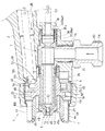
図1は本発明に係るスプレーガン1の第1実施形態についてその主要部(先端部分)を示した側断面図である。このスプレーガン1は、ガン本体2と、このガン本体2の先端に装着された噴霧ノズル3とを有している。またガン本体2の先端には、噴霧ノズル3の先端回りを取り囲むようにしてエアキャップ4が装着されている。
なお、ガン本体2には外部から塗料の供給を受ける塗料供給部2Aと、外部からエアの供給を受けるエア供給部2Bとが各別に設けられており、塗料供給部2Aにはトリガーレバーの操作によって開弁方向に移動し、通常時には、スプリングによって閉弁方向に押圧付勢されているニードル弁100が組み込まれて塗料通過量を調節可能になっており、またエア供給部2Bにはネジ螺進構造を備えたニードル弁105が組み込まれてエア通過量を調節可能になっている。Hereinafter, embodiments of the present invention will be described with reference to the drawings.
FIG. 1 is a side sectional view showing a main part (tip portion) of a spray gun 1 according to a first embodiment of the present invention. The spray gun 1 has a gun body 2 and a
The gun body 2 is provided with a
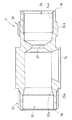
図2に示すように、噴霧ノズル3はノズル主体5とエアガイド部材6とを有しており、これらを別々に分解することができる(ノズル主体5を図3に示しエアガイド部材6を図4及び図5に示す)。また、この噴霧ノズル3はノズル主体5とエアガイド部材6とをガン本体2に同心状に組み込むための組付筒体7(図6に示す)を有しており、この組付筒体7を介してガン本体2に装着可能となっている。そしてノズル主体5の後端部5bの外周面が組付筒体7の先端部7aの内周面にテーパー嵌合(挿入)され、またエアガイド部材6の後端部6bの内周面が組付筒体7の先端部7aの外周面に螺合されるようになっている。組付筒体7の軸方向途中には、ガン本体2の塗料供給部2Aに連通する横孔7cが形成されている。塗料供給部2Aには、塗料接続管60が装着されている。塗料接続管60は、ガン本体2の先端よりも若干後方位置の下面に形成された接続口2Cに螺合接続され、先端部を組付筒体7の横孔7cに嵌合させて組付筒体7の回り止めを行わせている。
As shown in FIG. 2, the
ノズル主体5とエアガイド部材6とは互いに同心の関係に組み立てられており、ノズル主体5の先端部5aには塗料噴出孔10が設けられ、ノズル主体5とエアガイド部材6との先端間(ノズル主体5の先端部5a外周面とエアガイド部材6の先端部6a内周面との環状隙間)には、円環状の塗料噴霧用エア噴出孔11が形成されるようになっている。当然に、これら塗料噴出孔10と塗料噴霧用エア噴出孔11との間も、互いに同心関係となっている。
図3に示すように、ノズル主体5は、先端部5aが細く絞られたストレートの円筒形に形成されており、この先端部5aの細く絞られた部分を軸方向に貫通する状態で塗料噴出孔10が形成されている。ノズル主体5の内部に形成される筒孔が塗料供給路12とされる。この塗料供給路12において、塗料噴出孔10の内側には前方になるほど径小化されたテーパ面が形成されており、このテーパ面が、塗料通過量を調節するためのニードル弁100に対する弁座13を形成している。The nozzle
As shown in FIG. 3, the nozzle
本実施形態では、ノズル主体5の先端部5aにおいて細く絞られた部分が円筒状に突出する形状としてあり、従ってその内部に形成された塗料噴出孔10も所定長さのストレート孔となっている。そのため、この塗料噴出孔10を経て噴射される塗料に直進指向性が付与され、噴射距離が可及的に遠くまで及ぶようになっている。
ノズル主体5の後端部5b寄りとなる外周面には、周方向に張り出す環状凸部14が設けられており、この環状凸部14を境とする後方は、環状凸部14の前方側に比べてやや肉厚が分厚くなるように形成されている。また、ノズル主体5の後端部5b外周面は、後方ほど径小となるテーパ面15として形成されている。In the present embodiment, the narrowed portion of the
An annular
ノズル主体5は、上記のように先端部5aの絞りや後端部5bのテーパ面15、及び環状凸部14の形成を除けば、略ストレートの円筒形をしたものであり、ネジなどの複雑な構造を有しない簡潔構造となっていると共に、後端部5b寄りの僅かな厚肉化を除けば薄肉円筒状部品となっているので、セラミックなどを形成材料として形成することができる。それ故、耐摩耗性に優れた部品とすることができる。
図4及び図5に示すように、エアガイド部材6は、ノズル主体5よりも一回り径大な円筒形を基本形として形成されたものであって、先端部6aは細く絞られ、軸方向中央部の外周面に周方向に張り出す鍔部20が設けられ、後端部6bの内周面には雌ねじ部21が形成されている。As described above, the nozzle
As shown in FIGS. 4 and 5, the
鍔部20の外周面は、スパナなどの工具を係合させるために例えば正面視正六角形等の正多角形に形成されたものであって、エアガイド部材6と組付筒体7との連結又は分離や、噴霧ノズル3としてのガン本体2への着脱を行わせるときに使用される。またこの鍔部20の後方には、ガン本体2への装着時にガン本体2の先端開口部51を閉鎖する接続リング52のテーパー内面53に当接し、該接続リング52を軸方向に押圧して前記開口部51を閉鎖させるためのテーパー外面29がエアガイド部材6の外周面に形成されている。接続リング52は、ガン本体2のエア供給部2Bからエアキャップ4へ供給されるエア通過量を調節する1つの弁孔54を備えている。接続リング52は、この弁孔54をニードル弁105に位置決め対応させてガン本体2に取り付けることができるように構成されている。
The outer peripheral surface of the
本実施形態では、鍔部20の前面に、エアキャップ4を同心的に位置決め当接させるためのテーパー凹部19が形成されており、このテーパー凹部19によってエアキャップ4の後端の円錐状のテーパー凸部を回転自在に嵌合当接させてある(図1参照)。なお、テーパー凹部19は、円錐状の当接部であればよい。
エアガイド部材6において、先端部6aの細く絞られた部分には軸方向に貫通する先端孔22が形成されている。この先端孔22にはノズル主体5の先端部5aを嵌め込むことができ、更にそのうえでノズル主体5の先端部5aまわりに周方向で一定の環状隙間(上記した塗料噴霧用エア噴出孔11)を形成可能となる内径に形成されている。In this embodiment, a
In the
本実施形態では、エアガイド部材6の先端部6aにおいて細く絞られた部分が円筒状に突出する形状としてあり、従ってその内部に形成された先端孔22も所定長さのストレート孔となっている。そのため、この先端孔22にノズル主体5の先端部5a(細く絞られた部分であって円筒状に突出する形状をした部分)が嵌め込まれて形成される上記の塗料噴霧用エア噴出孔11も所定長さのストレート円筒孔となっている。そのため、この塗料噴霧用エア噴出孔11を経て噴射されるエアに直進指向性が付与され(無用な拡散性が抑制され)、噴射距離が可及的に遠くまで及ぶようになっている。
In the present embodiment, the narrowed portion of the
エアガイド部材6の内部に形成された筒孔23は、前方では上記先端孔22と連通し、また後方も雌ねじ部21を通り越して開放されている。この筒孔23にはノズル主体5における環状凸部14より前方側を挿入することができ、更にそのうえでノズル主体5のまわりに周方向で一定の環状隙間を形成可能となる内径に形成されている。言うまでもなく、ここに形成される環状隙間は、先端孔22とノズル主体5の先端部5aまわりとで形成される上記の塗料噴霧用エア噴出孔11に対し、相互連通するものであって、これによりエア通路25を形成することになる(図2参照)。
A
エアガイド部材6には、鍔部20より後方であって且つ雌ねじ部21よりは前方となる位置で、筒壁を貫通する径方向孔26が形成されており、この径方向孔26によってエア通路25がエアガイド部材6の内外を連通するものとなっている。この径方向孔26は、少なくとも1個あればよいが、筒壁の周方向に沿って複数設けるようにするのがよい。この径方向孔26が設けられていることにより、上記エア通路25は、噴霧ノズル3がガン本体2へ組み込まれたときにガン本体2のエア供給部2Bと連通する状態とされる。
なお、エアガイド部材6には、鍔部20より前方であって且つ先端孔22よりは後方となる位置で、筒壁を貫通する第2の径方向孔27が形成されている。この第2の径方向孔27によっても、エア通路25はエアガイド部材6の内外で連通した状態とされている。1個でも複数個でもよい事情については上記径方向孔26の場合と同じである。この第2の径方向孔27が設けられていることにより形成されるエアの流通路に関しては後述する。The
The
上記した雌ねじ部21の内径(ネジ山位置での内径)は筒孔23の内径よりも径大に形成されており、この雌ねじ部21の最奥部であって筒孔23との境部となる位置には、径方向に拡大した環状凹部28が形成されている。この環状凹部28は、雌ねじ部21の加工を容易にするための作用と共に、環状凹部28から筒孔23へ臨む位置にできる環状肩部28aにより、ノズル主体5の環状凸部14を当て止めして位置決めする作用を奏するものとなっている(図2参照)。
このエアガイド部材6は、真鍮やアルミ、銅、鉄、ステンレス等の適宜金属材を形成材料として無垢材又は鋳物素材からの削り出しによって製作すればよい。場合によっては樹脂材を形成材料とすることも可能である。The inner diameter (inner diameter at the screw thread position) of the
The
図6に示すように、組付筒体7は、エアガイド部材6と同程度の円筒形を基本形として形成されたものであって、先端部7aの内周面にはノズル主体5用の連結部32が設けられ、先端部7aの外周面にはエアガイド部材6用の連結部33が設けられている。
ノズル主体5用の連結部32には、ノズル主体5の後端部5bに形成されたテーパ面15とテーパー嵌合が可能なように、円錐状のテーパ状面32aが形成されており、エアガイド部材6用の連結部33には、エアガイド部材6の後端部6bに設けられた雌ねじ部21と螺合が可能なように雄ねじ部33aが設けられている。As shown in FIG. 6, the assembled
The connecting
一方、組付筒体7の後端部7bには、尾部キャップ連結部34と連結部35とが設けられている。尾部キャップ連結部34は、ニードル弁100の弁軸101を摺動自在に保持し且つ塗料漏れを止める尾部キャップ36(図1参照)を取り付けるためのもので、本実施形態では尾部キャップ36が雄ねじ部36aを具備したものとしてこの雄ねじ部36aと螺合可能な雌ねじ部34aが形成されたものとしてある。
なお、本実施形態では組付筒体7の軸方向中途部にも内径を絞って形成した弁軸受け37を設けてあり、ニードル弁100の弁軸101を2点支持できるようにしてある。これにより、弁軸101に円滑で安定した摺動が得られるようになり、ノズル主体5の弁座13に対するニードル弁100の当接及び離反が同軸関係を保証され、偏摩耗が生じないようになっている。On the other hand, a tail
In the present embodiment, a valve bearing 37 formed with a narrowed inner diameter is also provided in the middle of the
また上記連結部35は、噴霧ノズル3の全体として、ガン本体2への取り付けに用いるためのもので、本実施形態ではガン本体2側に雌ねじ部38(図1参照)が設けられたものとしてこの雌ねじ部38に螺合可能な雄ねじ部35aが形成されたものとしてある。
図2から明らかなように、ノズル主体5、エアガイド部材6、及び組付筒体7を連結することで噴霧ノズル3を形成させた状態では、ノズル主体5の後端部5bの外周のテーパ面15と組付筒体7のノズル主体5用の連結部32の内周のテーパ状面32aとがテーパー嵌合し、エアガイド部材6の環状凹部28から筒孔23へ臨む位置に設けられた環状肩部28aによりノズル主体5の環状凸部14が後方へ押圧され、これで上記テーパー嵌合が強められるようになりながら、エアガイド部材6の後端部6bの内周の雌ねじ部21と組付筒体7のエアガイド部材6用の連結部33の外周の雄ねじ部33aとが螺合されるようになっている。Further, the connecting
As apparent from FIG. 2, in the state where the
図1に示すように、エアキャップ4は、短筒形をしたロックナット40を接続リング52の外周面の雄ねじ部55に螺合することによってガン本体2の先端に装着されるようになっている。そのため、エアキャップ4の外周面にはロックナット40と軸方向では係合するが周方向では回転自在な状態を保持させるための環状リブ41が形成されている。
このエアキャップ4は、噴霧ノズル3の先端部を貫通して前方へ突出させるように、前壁4aに開口径の大きな中央口43が形成されていると共に、この中央口43を挟んだ径方向の両側位置で前方へ向けて角状に突出する上下一対の突起(角=ホーン)部44を有している。そして、これら両側の突起44には制御用エア噴出孔45が形成されている。As shown in FIG. 1, the air cap 4 is attached to the tip of the gun body 2 by screwing a
The air cap 4 has a
各突起44には、ガン本体2内のエア供給部2Bから、接続リング52の弁孔54を経由し、さらに、噴霧ノズル3におけるエアガイド部材6の外周とロックナット40の内周との間に環状に形成されたエア通路46を通してエアが供給される。従って、このエア通路46から各突起44内へ送り込まれたエアが制御用エア噴出孔45から噴出される。この噴出エアは、噴霧ノズル3の外側を被覆するようになって、噴霧ノズル3の先端から円錐状に噴霧される塗料噴霧形態を、楕円形乃至長円形を底とする扁平な錐形へと制御するようになる。そのため、接続リング52の弁孔54からのエア通過量をニードル弁105で制御することにより、塗料噴霧形態を制御して用途や目的等に応じた塗装が行えるようになる。
Each protrusion 44 is connected to the
なお、上記したようにエアキャップ4はガン本体2の先端部で回転自在な状態に保持されているので、このエアキャップ4の回転角を調節することで、噴霧ノズル3の先端から円錐状に噴霧される塗料噴霧形態に対し、突起44の制御用エア噴出孔45から噴出されるエアの吹き付け位置を変えることができる。
すなわち、噴霧ノズル3の先端から噴霧される塗料噴霧形態を、楕円形乃至長円形を底とする扁平な錐形とさせる場合にあって、楕円形乃至長円形が縦長となる姿勢としたり横長となる姿勢としたり、或いは斜め向きとなる姿勢としたりすることが任意に選択できるものである。As described above, since the air cap 4 is held in a freely rotatable state at the tip of the gun body 2, by adjusting the rotation angle of the air cap 4, a conical shape is formed from the tip of the
That is, in the case where the paint spraying form sprayed from the tip of the
エアキャップ4において、噴霧ノズル3(エアガイド部材6)に設けられた鍔部20より前方側を取り囲むようになる部分では、噴霧ノズル3の外周とこのエアキャップ4の内周との間に環状の補助エア通路48が形成されるようになっている。この補助エア通路48は、エアキャップ4における中央口43の内周面と、この中央口43から突出する噴霧ノズル3の外周面との接触によって仕切られている。
これに対し、エアキャップ4の前壁4a(即ち、中央口43の開口周部)には、周方向に所定間隔をおいて複数の補助エア噴出孔49が形成されている。従って、これら補助エア噴出孔49には補助エア通路48を介してエアが供給され、前方へ向けて噴射されるようになっている。In the air cap 4, an annular portion is formed between the outer periphery of the
On the other hand, a plurality of auxiliary air ejection holes 49 are formed in the
なお、上記したように補助エア通路48は、噴霧ノズル3の第2の径方向孔27を介し、エアガイド部材6の筒孔23とノズル主体5の外周との間で形成されたエア通路25と連通しており、このエア通路25は、噴霧ノズル3の後方側の径方向孔26を介してガン本体2のエア供給部2Bと連通しているので、結果、ガン本体2側からエア通路25へと供給されるエアが途中で補助エア噴出孔49へと分岐供給される状態にある。
かくして、補助エア通路48から補助エア噴出孔49を介して前方へと噴出するエアは、噴霧ノズル3の先端から噴射される塗料噴霧形態に対してそれが拡散するのを防止するカーテンを形成する状態となり、塗料をより遠くへ飛ばす作用を奏することになる。As described above, the
Thus, the air ejected forward from the
なお、本実施形態では、各補助エア噴出孔49が軸方向に対して内向きに傾斜した状態で形成させた。しかし軸方向に平行させるようにしてもよい。
以上、詳説したところから明かなように、本発明に係るスプレーガン1において、噴霧ノズル3がノズル主体5とエアガイド部材6とによって形成されるものであるから、交換予定部品としては、ノズル主体5だけとさせることができる。この場合、ノズル主体5とエアガイド部材6との内外周面間でエア通路25を形成させるようにしており、これをもって噴霧ノズル3には軸方向の孔を形成させる孔明け加工の必要がなくなっている。In the present embodiment, each auxiliary
As described above in detail, in the spray gun 1 according to the present invention, since the
それ故、ノズル主体5は薄肉円筒状部品で安価に形成することができるものであり、軸方向の孔明け加工等の複雑な加工も不要化できる。また、ノズル主体5は複雑な加工が不要であることから、耐摩耗性に優れたセラミックを形成材料として形成させることも可能になる。これにより、交換の頻度自体を低く抑制でき、使用者に対する交換作業の煩わしさを解消する利点にも繋がる。
エアガイド部材6には径方向孔26が形成されているために、わざわざ軸方向の孔を形成させる必要がない。そのため、エアガイド部材6(頻繁な交換を予定していない部品)としても薄肉円筒状部品で安価に形成でき、複雑な加工が不要であるから、スプレーガン1全体としての低廉化が可能となる。Therefore, the nozzle
Since the
噴霧ノズル3は組付筒体7を介してガン本体2へ装着されるので、ガン本体2に対する噴霧ノズル3の装着は簡単且つ確実となり、しかもノズル主体5とエアガイド部材6との内外周間隔を一定化させる(同心精度を高くさせる)ことが簡単且つ確実となる。従って塗装装置としての性能を向上させることにも繋がる。
図7は本発明に係るスプレーガンの第2実施形態を示す側断面図であって、ノズル主体5の外周面の環状凸部14とエアガイド部材6の内周面の環状肩部28aとの当接面をテーパー状当接面14aとし、これらをテーパー嵌合させたものである。この第2実施形態では、ノズル主体5とエアガイド部材6との同心性を第1実施形態よりも向上させている。第2実施形態における他の構成は、前述した第1実施形態とほぼ同様であって、同一部材には同一符号を付してその説明を省略する。Since the
FIG. 7 is a side sectional view showing a second embodiment of the spray gun according to the present invention, in which an annular
図8及び図9は本発明に係るスプレーガンの第3実施形態及び第4実施形態を示す側断面図であって、いずれも、エアガイド部材6の先端をノズル主体5の先端まで延長せずに途中までとし、エアキャップ4の前壁4aを中心方向に延長して、ノズル主体5の先端周囲に前記エア通路25と連通して塗料噴霧用エアを噴出するためのエア噴出孔11を形成する環状壁部4bをエアキャップ4に一体に形成したものである。なお、環状壁部4bには、補助エア噴出孔49が適宜形成されており、この補助エア噴出孔49には、エア通路25から直接的にエアが供給される。この補助エア噴出孔49からエアを噴出させることによって、中心部のエア噴出孔11及び塗料噴出孔10から前方に噴出される塗料噴霧形態の拡散を防止するエアカーテンの作用をさせ、直進性を向上させることができる。しかし、用途や目的によっては、補助エア噴出孔49は、省略してもよい。これら第3実施形態及び第4実施形態における他の構成は、第1実施形態及び第2実施形態とほぼ同様であり、同一部材には同一符号を付してその説明を省略する。
FIGS. 8 and 9 are side sectional views showing the third and fourth embodiments of the spray gun according to the present invention, and neither of them extends the tip of the
なお、第3実施形態と第4実施形態とは、次の点で相違している。即ち、第3実施形態は、エアガイド部材6が、先端を鍔部20の位置までとして長さを短縮し、エア噴出孔11を形成しないことによって先端形状を簡単化している。これに対して、第4実施形態は、エアガイド部材6が、先端を鍔部20よりもやや前方まで延長しているが、第1実施形態及び第2実施形態に比べて短縮し、エア噴出孔11を形成しないことによって先端形状を簡単化している。そして、鍔部20よりも前方に延長した部分6dの外周面をスパナ等の工具が係合する六角形等の正多角形状とし、その代わりに鍔部20の外周面は、正多角形ではなく、それよりも径の小さい円形としてエアキャップ4側へのエアの流通抵抗を低減させるようにしたものである。
The third embodiment and the fourth embodiment are different in the following points. That is, in the third embodiment, the
本発明の実施形態は以上であるが、本発明は、上記実施形態に限定されるものではなく、適宜変更可能である。 Although the embodiments of the present invention are as described above, the present invention is not limited to the above-described embodiments, and can be appropriately changed.
本発明のスプレーガンは、塗装作業に好適に利用されるが、果樹栽培、園芸等で薬液の散布や液体肥料の散布等にも利用可能であり、これら以外の用途に利用することも可能である。 The spray gun of the present invention is suitably used for painting operations, but can also be used for spraying chemicals and liquid fertilizers in fruit tree cultivation, horticulture, etc., and can be used for other purposes. is there.
Claims (8)
前記噴霧ノズルを前記ガン本体の塗料供給部からの塗料を通す塗料供給路が中心部に軸方向に貫通して形成され、この塗料供給路の先端側に塗料噴出孔が開口形成されている筒体形状のノズル主体と、前記ノズル主体の外側周囲に嵌合され、内周面を前記ガン本体のエア供給部に連通させた筒体形状のエアガイド部材とに分けて構成すると共に、前記ノズル主体をセラミックで構成し、
前記ノズル主体とエアガイド部材とは、ガン本体に螺合された組付筒体を介して前記ガン本体に組み付けられており、前記ノズル主体は、後端を組付筒体の先端に挿入され、前記エアガイド部材は、後端を組付筒体の先端に螺合され、前記ガン本体の塗料供給部と前記ノズル主体の塗料供給路とは前記組付筒体によって連通するように構成されており、
前記エアガイド部材には、前記ガン本体のエア供給部からのエアを前記エア噴出孔に向けて供給する環状エア通路が形成され、この環状エア通路は、前記ノズル主体の外周面とエアガイド部材の内周面とで軸方向に沿って形成してあることを特徴とするスプレーガン。A gun body provided with a paint supply unit and an air supply unit, and a paint ejection hole which is attached to the gun body and whose paint passage amount can be adjusted by a needle valve at the center, and an annular air jet around the paint ejection hole In a spray gun comprising a spray nozzle that forms a hole, a control air ejection hole that controls a paint spraying form of the spray nozzle, and an air cap that is mounted on the gun body together with the spray nozzle,
A cylinder in which a paint supply path through which the paint from the paint supply section of the gun body passes through the spray nozzle is formed so as to penetrate the central portion in the axial direction, and a paint ejection hole is formed at the front end side of the paint supply path The nozzle main body is divided into a body-shaped nozzle main body and a cylindrical air guide member that is fitted around the outer periphery of the nozzle main body and communicates with the air supply portion of the gun body. The main body is made of ceramic ,
The nozzle body and the air guide member are assembled to the gun body via an assembly cylinder that is screwed to the gun body, and the nozzle body has a rear end inserted into the tip of the assembly cylinder. The air guide member is configured such that the rear end is screwed into the tip of the assembly cylinder, and the paint supply portion of the gun body and the paint supply path mainly composed of the nozzle communicate with each other by the assembly cylinder. And
The air guide member is formed with an annular air passage for supplying air from the air supply portion of the gun body toward the air ejection hole. The annular air passage is formed between the outer peripheral surface of the nozzle main body and the air guide member. A spray gun formed along the axial direction with the inner peripheral surface of the spray gun.
前記噴霧ノズルを前記ガン本体の塗料供給部からの塗料を通す塗料供給路が中心部に軸方向に貫通して形成され、この塗料供給路の先端側に塗料噴出孔が開口形成されている筒体形状のノズル主体と、前記ノズル主体の外側周囲に嵌合され、内周面を前記ガン本体のエア供給部に連通させた筒体形状のエアガイド部材とに分けて構成すると共に、前記ノズル主体をセラミックで構成し、
前記ノズル主体とエアガイド部材とは、ガン本体に螺合された組付筒体を介して前記ガン本体に組み付けられ、前記ガン本体の塗料供給部と前記ノズル主体の塗料供給路とは前記組付筒体によって連通するように構成されており、
前記エアガイド部材には、前記ガン本体のエア供給部からのエアを前記エアガイド部材に形成された径方向の孔から導入して前記エア噴出孔に向けて供給する環状エア通路が形成され、この環状エア通路は、前記ノズル主体の外周面とエアガイド部材の内周面とで軸方向に沿って形成してあることを特徴とするスプレーガン。 A gun body provided with a paint supply unit and an air supply unit, and a paint ejection hole which is attached to the gun body and whose paint passage amount can be adjusted by a needle valve at the center, and an annular air jet around the paint ejection hole A spray nozzle that forms a hole, and an air cap that is provided with a control air ejection hole that controls the paint spraying form of the spray nozzle and is screwed to the gun body with a lock nut via a connection ring together with the spray nozzle. In the provided spray gun,
A cylinder in which a paint supply path through which the paint from the paint supply section of the gun body passes through the spray nozzle is formed so as to penetrate the central portion in the axial direction, and a paint ejection hole is formed at the front end side of the paint supply path The nozzle main body is divided into a body-shaped nozzle main body and a cylindrical air guide member that is fitted around the outer periphery of the nozzle main body and communicates with the air supply portion of the gun body. The main body is made of ceramic,
The nozzle main body and the air guide member are assembled to the gun main body via an assembly cylinder screwed to the gun main body, and the paint supply portion of the gun main body and the paint supply path of the nozzle main body are It is configured to communicate with the attached cylinder,
The air guide member is formed with an annular air passage that introduces air from an air supply portion of the gun body from a radial hole formed in the air guide member and supplies the air toward the air ejection hole. The annular air passage is formed along the axial direction between the outer peripheral surface of the nozzle main body and the inner peripheral surface of the air guide member .
Applications Claiming Priority (3)
| Application Number | Priority Date | Filing Date | Title |
|---|---|---|---|
| JP2007019618 | 2007-01-30 | ||
| JP2007019618 | 2007-01-30 | ||
| PCT/JP2007/064599 WO2008093441A1 (en) | 2007-01-30 | 2007-07-25 | Spray gun |
Publications (2)
| Publication Number | Publication Date |
|---|---|
| JP4200181B2 true JP4200181B2 (en) | 2008-12-24 |
| JPWO2008093441A1 JPWO2008093441A1 (en) | 2010-05-20 |
Family
ID=39673757
Family Applications (1)
| Application Number | Title | Priority Date | Filing Date |
|---|---|---|---|
| JP2007552428A Expired - Fee Related JP4200181B2 (en) | 2007-01-30 | 2007-07-25 | Spray gun |
Country Status (8)
| Country | Link |
|---|---|
| US (1) | US20090121048A1 (en) |
| EP (1) | EP2108460A4 (en) |
| JP (1) | JP4200181B2 (en) |
| KR (1) | KR100990080B1 (en) |
| CN (1) | CN101410188B (en) |
| HK (1) | HK1128256A1 (en) |
| MY (1) | MY149966A (en) |
| WO (1) | WO2008093441A1 (en) |
Families Citing this family (24)
| Publication number | Priority date | Publication date | Assignee | Title |
|---|---|---|---|---|
| DE102007053855A1 (en) * | 2007-02-27 | 2008-09-04 | Martin Ruda | Paint spray pistol has base with main contact region for replaceable paint conductor that is formed by outer base surface |
| CN105107653B (en) | 2009-01-26 | 2018-01-09 | 3M创新有限公司 | Liquid spray gun, spray gun platform and nozzle component |
| EP2492018B1 (en) * | 2009-10-20 | 2015-05-06 | Freund Corporation | Spray gun |
| EP3476492B1 (en) | 2011-02-09 | 2020-05-27 | 3M Innovative Properties Co. | Nozzle tips and spray head assemblies for liquid spray guns |
| WO2013016474A1 (en) | 2011-07-28 | 2013-01-31 | 3M Innovative Properties Company | Spray head assembly with integrated air cap/nozzle for a liquid spray gun |
| WO2013055730A1 (en) * | 2011-10-12 | 2013-04-18 | 3M Innovative Properties Company | Spray head assemblies for liquid spray guns |
| MX370998B (en) | 2012-03-06 | 2020-01-13 | 3M Innovative Properties Co | Spray gun having internal boost passageway. |
| KR102111467B1 (en) * | 2012-03-23 | 2020-05-15 | 쓰리엠 이노베이티브 프로퍼티즈 컴파니 | Spray gun barrel with inseparable nozzle |
| AU2014290641B2 (en) | 2013-07-15 | 2017-07-06 | 3M Innovative Properties Company | Air caps with face geometry inserts for liquid spray guns |
| CN103521378B (en) * | 2013-09-26 | 2016-09-07 | 宁波李氏实业有限公司 | A kind of spray gun device |
| JP6267538B2 (en) * | 2014-02-21 | 2018-01-24 | アネスト岩田株式会社 | Spray gun |
| JP2015217346A (en) * | 2014-05-19 | 2015-12-07 | アネスト岩田株式会社 | Coater and coating method |
| EP3154707B2 (en) * | 2014-06-10 | 2022-08-17 | 3M Innovative Properties Company | Nozzle assembly with external baffles |
| JP6444163B2 (en) * | 2014-12-22 | 2018-12-26 | アネスト岩田株式会社 | Spray gun |
| US9533316B2 (en) * | 2015-03-31 | 2017-01-03 | Stolle Machinery Company, Llc | Spray gun with air halo nozzle assembly |
| JP6531939B2 (en) * | 2015-04-09 | 2019-06-19 | アネスト岩田株式会社 | Automatic spray gun |
| CN105537020B (en) * | 2015-12-30 | 2018-01-23 | 向卫东 | Nozzle is set with and spray gun |
| US11020759B2 (en) * | 2016-04-20 | 2021-06-01 | Carlisle Fluid Technologies, Inc. | System for controlling air shaping flow in spray cap of spray tool |
| WO2021257564A1 (en) * | 2020-06-19 | 2021-12-23 | Graco Minnesota Inc. | Fluid sprayer and components of a fluid sprayer |
| KR102383622B1 (en) * | 2020-09-28 | 2022-04-05 | 조명제 | water-soluble latex spray gun |
| CN112942752B (en) * | 2021-01-28 | 2022-12-09 | 广州天翔建设工程有限公司 | Paint spraying device and method for construction site |
| JP7034352B1 (en) * | 2021-03-25 | 2022-03-11 | 株式会社スギノマシン | nozzle |
| CN113174642A (en) * | 2021-04-30 | 2021-07-27 | 苏州市吴中喷丝板有限公司 | Superhard ceramic high-speed kinetic energy gun body for epidemic prevention spinneret body and preparation method |
| CN115027056B (en) * | 2022-06-11 | 2023-12-08 | 上海占瑞模具设备有限公司 | 3D printing hot runner nozzle tip structure and preparation process thereof |
Family Cites Families (20)
| Publication number | Priority date | Publication date | Assignee | Title |
|---|---|---|---|---|
| USRE19907E (en) * | 1936-03-31 | Means for coating by spraying | ||
| US5080285A (en) * | 1988-07-11 | 1992-01-14 | Toth Denis W | Automatic paint spray gun |
| JPH02107364A (en) * | 1988-10-17 | 1990-04-19 | Asahi Okuma Ind Co Ltd | Air spray gun |
| US5170941A (en) * | 1989-04-20 | 1992-12-15 | Iwata Air Compressor Mfg. Co., Ltd. | Premixing-type spray gun |
| JPH0737728Y2 (en) * | 1989-08-11 | 1995-08-30 | 岩田塗装機工業株式会社 | Spray gun with internal mixing and atomization |
| US5322221A (en) * | 1992-11-09 | 1994-06-21 | Graco Inc. | Air nozzle |
| JP2769962B2 (en) * | 1993-04-21 | 1998-06-25 | アロイ工器株式会社 | Air-added sprayer suitable for painting |
| US5799875A (en) * | 1995-03-30 | 1998-09-01 | Asahi Sunac Corporation | HVLP spray gun and integrated fluid nozzle therefor |
| JP3633233B2 (en) * | 1996-11-12 | 2005-03-30 | 日産自動車株式会社 | Air spray gun |
| US6085996A (en) * | 1998-03-05 | 2000-07-11 | Coating Atomization Technologies, Llc | Two-piece spray nozzle |
| FR2788231B1 (en) * | 1999-01-11 | 2001-03-09 | Itw Surfaces & Finitions | SPRAY HEAD OF A PRODUCT SUCH AS PAINT |
| AU4394399A (en) * | 1999-06-30 | 2001-01-22 | Anest Iwata Corporation | Low-pressure atomizing spray gun |
| US6293476B1 (en) | 2000-06-28 | 2001-09-25 | Illinois Tool Works Inc. | Spray gun nozzle assembly air cap |
| CN2442755Y (en) * | 2000-09-14 | 2001-08-15 | 黄条祥 | Replaceable spray pistol nozzle structure |
| DE10127693A1 (en) * | 2001-06-08 | 2002-12-12 | Walter Swoboda | Jet for two substances has cylindrical vortex chamber downstream of metering jets |
| JP3737731B2 (en) * | 2001-10-03 | 2006-01-25 | 株式会社明治機械製作所 | Paint nozzle fitting for air spray gun and air spray gun using the same |
| FR2839663B1 (en) * | 2002-05-16 | 2004-07-23 | Itw Surfaces & Finitions | SPRAY HEAD OF A PRODUCT SUCH AS PAINT |
| FR2863512B1 (en) * | 2003-12-10 | 2006-01-21 | Itw Surfaces & Finitions | AUTOMATIC SPRAY GUN |
| US20080116296A1 (en) * | 2006-11-22 | 2008-05-22 | Chung-Tsuen Juo | Spray gun |
| JP2010137202A (en) * | 2008-12-15 | 2010-06-24 | Meiji Kikai Seisakusho:Kk | Automatic spray gun |
-
2007
- 2007-07-25 MY MYPI20092863A patent/MY149966A/en unknown
- 2007-07-25 KR KR1020087021991A patent/KR100990080B1/en active IP Right Grant
- 2007-07-25 CN CN2007800110809A patent/CN101410188B/en not_active Expired - Fee Related
- 2007-07-25 US US12/296,290 patent/US20090121048A1/en not_active Abandoned
- 2007-07-25 WO PCT/JP2007/064599 patent/WO2008093441A1/en active Application Filing
- 2007-07-25 EP EP07791315A patent/EP2108460A4/en not_active Withdrawn
- 2007-07-25 JP JP2007552428A patent/JP4200181B2/en not_active Expired - Fee Related
-
2009
- 2009-07-03 HK HK09105986.6A patent/HK1128256A1/en not_active IP Right Cessation
Also Published As
| Publication number | Publication date |
|---|---|
| KR20080103064A (en) | 2008-11-26 |
| EP2108460A1 (en) | 2009-10-14 |
| CN101410188B (en) | 2011-04-13 |
| CN101410188A (en) | 2009-04-15 |
| HK1128256A1 (en) | 2009-10-23 |
| KR100990080B1 (en) | 2010-10-29 |
| WO2008093441A1 (en) | 2008-08-07 |
| MY149966A (en) | 2013-11-15 |
| JPWO2008093441A1 (en) | 2010-05-20 |
| US20090121048A1 (en) | 2009-05-14 |
| EP2108460A4 (en) | 2011-05-18 |
Similar Documents
| Publication | Publication Date | Title |
|---|---|---|
| JP4200181B2 (en) | Spray gun | |
| US9358559B2 (en) | Spray gun | |
| EP3508279B1 (en) | Air cap arrangement and spray gun | |
| US4744518A (en) | Fan adjustment for paint spray gun | |
| US6612506B1 (en) | Spray gun head with dual air ports & a diverter bushing | |
| JP2008194696A (en) | Spray gun | |
| US9498788B2 (en) | Spray gun | |
| US9358558B2 (en) | Spray gun | |
| US9358560B2 (en) | Spray gun | |
| US20140246516A1 (en) | Replaceable head part of probe of spray gun | |
| WO2016104346A1 (en) | Spray gun | |
| US2146416A (en) | Spray gun nozzle | |
| JP2019093438A (en) | Laser nozzle | |
| US9302278B2 (en) | Nozzle of spray gun | |
| WO2018230589A1 (en) | Spray gun | |
| JP2020078771A (en) | Fluid nozzle | |
| CN211587114U (en) | Nozzle applied to paint spray gun | |
| JP2006192405A (en) | Spray gun for coating work | |
| US20080251606A1 (en) | Air Spray Gun Improvements in Nozzle and Aircap | |
| US20180185863A1 (en) | Gardening water spray gun | |
| JP2009050820A (en) | Paint gun | |
| KR101584721B1 (en) | Two-fluid jetting nozzle | |
| JPH1147645A (en) | Airless gun using air jointly | |
| JP2017035673A (en) | Spray gun | |
| CN103836628A (en) | Welding and cutting torch |
Legal Events
| Date | Code | Title | Description |
|---|---|---|---|
| TRDD | Decision of grant or rejection written | ||
| A01 | Written decision to grant a patent or to grant a registration (utility model) |
Free format text: JAPANESE INTERMEDIATE CODE: A01 Effective date: 20080930 |
|
| A01 | Written decision to grant a patent or to grant a registration (utility model) |
Free format text: JAPANESE INTERMEDIATE CODE: A01 |
|
| A61 | First payment of annual fees (during grant procedure) |
Free format text: JAPANESE INTERMEDIATE CODE: A61 Effective date: 20081006 |
|
| FPAY | Renewal fee payment (event date is renewal date of database) |
Free format text: PAYMENT UNTIL: 20111010 Year of fee payment: 3 |
|
| R150 | Certificate of patent or registration of utility model |
Ref document number: 4200181 Country of ref document: JP Free format text: JAPANESE INTERMEDIATE CODE: R150 Free format text: JAPANESE INTERMEDIATE CODE: R150 |
|
| FPAY | Renewal fee payment (event date is renewal date of database) |
Free format text: PAYMENT UNTIL: 20111010 Year of fee payment: 3 |
|
| FPAY | Renewal fee payment (event date is renewal date of database) |
Free format text: PAYMENT UNTIL: 20121010 Year of fee payment: 4 |
|
| R250 | Receipt of annual fees |
Free format text: JAPANESE INTERMEDIATE CODE: R250 |
|
| FPAY | Renewal fee payment (event date is renewal date of database) |
Free format text: PAYMENT UNTIL: 20121010 Year of fee payment: 4 |
|
| FPAY | Renewal fee payment (event date is renewal date of database) |
Free format text: PAYMENT UNTIL: 20131010 Year of fee payment: 5 |
|
| R250 | Receipt of annual fees |
Free format text: JAPANESE INTERMEDIATE CODE: R250 |
|
| R250 | Receipt of annual fees |
Free format text: JAPANESE INTERMEDIATE CODE: R250 |
|
| R250 | Receipt of annual fees |
Free format text: JAPANESE INTERMEDIATE CODE: R250 |
|
| A621 | Written request for application examination |
Free format text: JAPANESE INTERMEDIATE CODE: A621 Effective date: 20071121 |
|
| A871 | Explanation of circumstances concerning accelerated examination |
Free format text: JAPANESE INTERMEDIATE CODE: A871 Effective date: 20071121 |
|
| R250 | Receipt of annual fees |
Free format text: JAPANESE INTERMEDIATE CODE: R250 |
|
| R250 | Receipt of annual fees |
Free format text: JAPANESE INTERMEDIATE CODE: R250 |
|
| R250 | Receipt of annual fees |
Free format text: JAPANESE INTERMEDIATE CODE: R250 |
|
| R250 | Receipt of annual fees |
Free format text: JAPANESE INTERMEDIATE CODE: R250 |
|
| R250 | Receipt of annual fees |
Free format text: JAPANESE INTERMEDIATE CODE: R250 |
|
| LAPS | Cancellation because of no payment of annual fees |