JP4199843B2 - Ink supply variable pressure control method - Google Patents
Ink supply variable pressure control method Download PDFInfo
- Publication number
- JP4199843B2 JP4199843B2 JP04954398A JP4954398A JP4199843B2 JP 4199843 B2 JP4199843 B2 JP 4199843B2 JP 04954398 A JP04954398 A JP 04954398A JP 4954398 A JP4954398 A JP 4954398A JP 4199843 B2 JP4199843 B2 JP 4199843B2
- Authority
- JP
- Japan
- Prior art keywords
- ink
- carriage
- print cartridge
- ink supply
- storage container
- Prior art date
- Legal status (The legal status is an assumption and is not a legal conclusion. Google has not performed a legal analysis and makes no representation as to the accuracy of the status listed.)
- Expired - Fee Related
Links
Images


Classifications
-
- B—PERFORMING OPERATIONS; TRANSPORTING
- B41—PRINTING; LINING MACHINES; TYPEWRITERS; STAMPS
- B41J—TYPEWRITERS; SELECTIVE PRINTING MECHANISMS, i.e. MECHANISMS PRINTING OTHERWISE THAN FROM A FORME; CORRECTION OF TYPOGRAPHICAL ERRORS
- B41J2/00—Typewriters or selective printing mechanisms characterised by the printing or marking process for which they are designed
- B41J2/005—Typewriters or selective printing mechanisms characterised by the printing or marking process for which they are designed characterised by bringing liquid or particles selectively into contact with a printing material
- B41J2/01—Ink jet
- B41J2/17—Ink jet characterised by ink handling
- B41J2/175—Ink supply systems ; Circuit parts therefor
- B41J2/17503—Ink cartridges
- B41J2/17506—Refilling of the cartridge
- B41J2/17509—Whilst mounted in the printer
-
- B—PERFORMING OPERATIONS; TRANSPORTING
- B41—PRINTING; LINING MACHINES; TYPEWRITERS; STAMPS
- B41J—TYPEWRITERS; SELECTIVE PRINTING MECHANISMS, i.e. MECHANISMS PRINTING OTHERWISE THAN FROM A FORME; CORRECTION OF TYPOGRAPHICAL ERRORS
- B41J2/00—Typewriters or selective printing mechanisms characterised by the printing or marking process for which they are designed
- B41J2/005—Typewriters or selective printing mechanisms characterised by the printing or marking process for which they are designed characterised by bringing liquid or particles selectively into contact with a printing material
- B41J2/01—Ink jet
- B41J2/17—Ink jet characterised by ink handling
- B41J2/175—Ink supply systems ; Circuit parts therefor
- B41J2/17503—Ink cartridges
- B41J2/17506—Refilling of the cartridge
-
- B—PERFORMING OPERATIONS; TRANSPORTING
- B41—PRINTING; LINING MACHINES; TYPEWRITERS; STAMPS
- B41J—TYPEWRITERS; SELECTIVE PRINTING MECHANISMS, i.e. MECHANISMS PRINTING OTHERWISE THAN FROM A FORME; CORRECTION OF TYPOGRAPHICAL ERRORS
- B41J2/00—Typewriters or selective printing mechanisms characterised by the printing or marking process for which they are designed
- B41J2/005—Typewriters or selective printing mechanisms characterised by the printing or marking process for which they are designed characterised by bringing liquid or particles selectively into contact with a printing material
- B41J2/01—Ink jet
- B41J2/17—Ink jet characterised by ink handling
- B41J2/175—Ink supply systems ; Circuit parts therefor
- B41J2/17503—Ink cartridges
- B41J2/17513—Inner structure
-
- B—PERFORMING OPERATIONS; TRANSPORTING
- B41—PRINTING; LINING MACHINES; TYPEWRITERS; STAMPS
- B41J—TYPEWRITERS; SELECTIVE PRINTING MECHANISMS, i.e. MECHANISMS PRINTING OTHERWISE THAN FROM A FORME; CORRECTION OF TYPOGRAPHICAL ERRORS
- B41J2/00—Typewriters or selective printing mechanisms characterised by the printing or marking process for which they are designed
- B41J2/005—Typewriters or selective printing mechanisms characterised by the printing or marking process for which they are designed characterised by bringing liquid or particles selectively into contact with a printing material
- B41J2/01—Ink jet
- B41J2/17—Ink jet characterised by ink handling
- B41J2/175—Ink supply systems ; Circuit parts therefor
- B41J2/17503—Ink cartridges
- B41J2/1752—Mounting within the printer
-
- B—PERFORMING OPERATIONS; TRANSPORTING
- B41—PRINTING; LINING MACHINES; TYPEWRITERS; STAMPS
- B41J—TYPEWRITERS; SELECTIVE PRINTING MECHANISMS, i.e. MECHANISMS PRINTING OTHERWISE THAN FROM A FORME; CORRECTION OF TYPOGRAPHICAL ERRORS
- B41J2/00—Typewriters or selective printing mechanisms characterised by the printing or marking process for which they are designed
- B41J2/005—Typewriters or selective printing mechanisms characterised by the printing or marking process for which they are designed characterised by bringing liquid or particles selectively into contact with a printing material
- B41J2/01—Ink jet
- B41J2/17—Ink jet characterised by ink handling
- B41J2/175—Ink supply systems ; Circuit parts therefor
- B41J2/17566—Ink level or ink residue control
Landscapes
- Ink Jet (AREA)
Description
【0001】
【発明の属する技術分野】
本発明はインクジェットプリンタおよび/またはインクジェットプロッタに係り、とりわけ軸外(off-axis)インクカートリッジの貯蔵容器の高さを変えて、キャリッジ搭載印字カートリッジの補充時間を減らし、インク補充体積の確実性を確保し、印字カートリッジの真空圧力を設定する技術に関する。
【0002】
【従来の技術】
印刷システムは、「インクジェットスウォスプリンタ/プロッタのばね袋インク貯蔵容器に連続的に補充する方法」という名称の、共通に譲渡されている特許出願に記載されている。これは、曲げることのできる管によりキャリッジ搭載印字カートリッジに接続されたキャリッジ外インク貯蔵容器が採用されている。キャリッジ外インク貯蔵容器は、オンキャリッジ印字カートリッジの内部貯蔵容器の中のインク供給品を連続的に補給し、背圧を高品位印刷の生ずる範囲に維持する。このシステムには多数の長所があるが、キャリッジ外インク貯蔵容器およびキャリッジ搭載貯蔵容器を管により相対的に永久接続することが望ましくないという用途が幾つか存在する。
【0003】
プリンタ/プロッタ用の新しいインク分配システム(IDS)が開発されており、それによれば、印字カートリッジのキャリッジ搭載ばね貯蔵容器がキャリッジ外インク貯蔵容器に単に周期的に接続されて「インクを瞬間充填(take a gulp)」してから、キャリッジ外インク貯蔵容器から切り離される。キャリッジ搭載要素とキャリッジ外要素とを永久的に接続する管は不要である。以上参照された関連出願、「複数の交換可能インク供給袋を共に組み込むための空間効率の良い外囲器形状」、「印刷ヘッドの周期的インク補充のための単一オンオフ制御バルブを備えた印刷システム」および「並列印刷ヘッドを備えたインク供給バルブの周期的自動接続のための装置」は、本発明の分配システムのある部分について記述している。
【0004】
本発明は、この新しいキャリッジ外(off-carriage)を備えた瞬間充填(take-a-gulp)インク分配システムを最適化するものである。この種のIDSでは、内部ばねを使用して真空圧力を与える印字カートリッジがキャリッジ走査軸を外れて設置されているインク貯蔵容器に周期的に接続される。「満杯の」印字カートリッジから始めて、プリンタ/プロッタは使用されるインクの量を監視しながら多様な描画を印刷する。指定量のインクが分配されてから、キャリッジはインク補給のため補充ステーションに移動する。この補充ステーションで、バルブが印字カートリッジに係合され、インク貯蔵容器が印字カートリッジに接続され、インクが自由に流れるための経路が開かれる。印字カートリッジに存在する真空圧力だけを使用して、インクは、貯蔵容器から印字カートリッジ内に引き込まれる。
【0005】
【発明が解決しようとする課題】
印字カートリッジの真空圧力は、印字カートリッジに入っているインクの量と共に変化する。通常、低いインク体積は高い真空圧力に関係し、高いインク体積は低い真空圧力に関係する。真空圧力−インク体積曲線はヒステリシスを示し、所定のインク体積に対して、印刷中(インク体積が減少する)に、補充するとき(インク体積が増大する)とは異なる真空圧力が印字カートリッジ内に生ずる。他に、補充真空圧力曲線にはそれにより幾つかのインク体積が同じ真空圧力を生ずる幾つかの相対的ピークまたは「隆起」がある。これは、この種の自己調整補充システムににおいて、印字カートリッジ内の真空圧力が、インク貯蔵容器が印字カートリッジの下で偏っている(offset)距離に等しいとき、印字カートリッジへのインクの流入が停止するという重大な問題を提示する。従って、所定の偏り(offset)距離に対して、印字カートリッジは常にオフセット距離に等しい圧力を生ずる最小体積まで補充される。これら最小の「締め括り」補充体積は予測不能であり、しばしば非常に小さく(印字カートリッジの貯蔵容器体積のほぼ半分)、これは望ましくない。
【0006】
【課題を解決するための手段】
この過小充填(underfilling)問題を回避するには、貯蔵容器の位置を垂直運動により上下に活動的に移動させる。バルブを印字カートリッジに係合させてから、貯蔵容器を印字カートリッジに非常に近接させて設置する(インク貯蔵容器の頂部を印字カートリッジのノズルの下約1/2″にする)。この貯蔵容器の位置で、オフセット距離は十分小さく、インクは、圧力−体積曲線の隆起の存在または大きさに関係なく、印字カートリッジに流入し続ける。他に、オフセット距離が小さくなれば、管内のインクの加速度が増大し、補充時間が速くなる。しかし、この位置では、印字カートリッジは過充填され、この場合、印字カートリッジの貯蔵容器の中の真空圧力が高印刷品質を確保するには小さすぎる。真空圧力を適切な範囲内にするには、貯蔵容器を下げると、少量のインクが貯蔵容器に逆流する。このわずかなインク体積の減少により真空圧力が適切な範囲内に上昇する。
【0007】
本発明のこれらおよび他の特徴および長所は、図面に示したように、例示された実施形態の下記詳細説明から一層明らかになるであろう。
【0008】
また、本発明は、1995年5月31日付けで出願された米国特許出願第08/454,975号、Joseph E. Scheffelin他の「インクジェットスウォスプリンタ/プロッタにおけるばね袋貯蔵の連続補充」の一部を改良したものである。関連する総合的な内容は、この米国特許出願第08/454,975号に記載されている。
【0009】
また、米国特許出願第08/454,975号は以下に関連している。Erich Coiner他の「複数の交換可能インク供給袋を共に組み込むための空間効率の良い外囲器形状」、Max S. Gunther他の「印刷ヘッドの周期的インク補充のための単一オンオフ制御バルブを備えた印刷システム」、Ignacio Olazabal他の「並列印刷ヘッドを備えたインク供給バルブの周期的自動接続のための装置」、Robert J. Katon他の「インクジェットカートリッジの充填ポートアダプタ」。
【0010】
【発明の実施の形態】
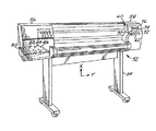
本発明の実施の形態は、大型印刷(LFP)用スウォス(swath)プロッタ/プリンタである。図1は、感熱式インクジェット大型プリンタ/プロッタ50の斜視図である。感熱式インクジェット大型プリンタ/プロッタ50は、左ハウジング56および右ハウジング58の付いたスタンド54に取付けられたハウジング52を備えている。キャリッジ組立体60がキャリッジ滑り棒に沿って往復移動するようになっている。紙のような印刷媒体が媒体軸駆動機構(図示せず)により垂直軸または媒体軸に沿って設置されている。当技術において、通常のように媒体駆動軸を「x」軸と名付け、キャリッジ走査軸を「y」軸と名付ける。
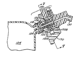
【0011】
図3は、キャリッジ組立体60、および補充ステーションの上面図である。キャリッジ組立体60は、滑り棒94A、94Bの上を滑る。水平軸またはキャリッジ走査軸に沿うキャリッジ組立体60の位置は、エンコーダストリップ92に関してキャリッジ位置決め機構により決定される。キャリッジ位置決め機構は、キャリッジ組立体60に取付けられたベルト96を駆動し、キャリッジを位置決めするキャリッジモータ404(図15)を備えている。走査軸に沿うキャリッジ組立体60の位置は、エンコーダストリップ92を使用することにより精密に決定される。キャリッジエンコーダセンサ406(図15)がキャリッジ組立体60上に設置され、最適画像整列および精密キャリッジ位置決めを行なうのに利用されるキャリッジ位置信号を発生する。適切なキャリッジ位置決め装置の更なる説明は、上に引用した米国特許出願第08/454,975号に示されている。
【0012】
感熱式インクジェット大型プリンタ/プロッタ50は、別々の色、例えば、黒、黄色、マゼンタおよびシアンのインクをそれぞれ貯蔵する4個の印字カートリッジ70〜76を内部ばね袋インク貯蔵容器に備えている。キャリッジ組立体60がy軸の方向に媒体に対して平行移動するとき、インクジェットカートリッジの所定のノズルが作動し、インクが媒体に加えられる。
【0013】
キャリッジ組立体60は、印字カートリッジ70〜76を位置決めし、印字カートリッジ70〜76内のヒータ回路(図示せず)に接続するのに必要な回路類を保持している。キャリッジ組立体60は、前のスライダ92Aおよび後のスライダ92Bの上を往復運動するようになっているキャリッジ62を備えている。印字カートリッジ70〜76は、緻密な実装構成として固定され、各々を新しいペンと交換するために選択的にキャリッジ組立体60から取り外すことができる。キャリッジ組立体60は、一対の対向側壁および離して設けられた短い内壁を備え、これらがカートリッジ区画室を形成している。キャリッジ組立体60の壁は、堅いエンジニヤリングプラスチックから製作される。印字カートリッジ70〜76の印字ヘッド106は、印刷媒体に面するカートリッジ区画室の開口を通して露出している。
【0014】
上記の通り、全カラー印刷および描画には個別印字カートリッジからの色を媒体に加える必要がある。これにより内部貯蔵容器104からインクが消耗する。感熱式インクジェット大型プリンタ/プロッタ50は、印刷システムのインク配給要請を満たすのに、4個の瞬間充填IDSを備えている。各IDSは、三つの構成要素、キャリッジ外インク貯蔵容器80〜86と、キャリッジ搭載の印字カートリッジ70〜76と、印字ヘッドクリーナと、を備えている。キャリッジ外インク貯蔵容器80〜86は、短い管および補充バルブが取付けられた、370mlのインクを保持する袋を備えている。この目的に適するインク貯蔵容器袋の構造の詳細は、Erich Coiner他の「複数の交換可能インク供給袋を共に組み込むための空間効率の良い外囲器形状」に述べられている。これらキャリッジ外インク貯蔵容器80〜86は、感熱式インクジェット大型プリンタ/プロッタ50の左側面に(左ハウジング56のドアの後)に取付けられ、バルブは下に説明するように、やはり左ハウジング56のドアの後で、バルブ保持器腕170に取付けられている。この例示された実施形態の印字カートリッジ70〜76は、これを通して補充される口の付いた、300個のノズルを備えた600dpiの印字ヘッド106を備えている。ヘッドクリーナ(図示せず)は、保守および印字ヘッド106を校正(calibrate)するとき使用されるインクを捕らえるスピツーン(spittoon)と、印字ヘッド面を拭くのに使用されるワイパと、キャップ(使用しないとき印字ヘッドを保護するのに使用される)とを備えている。これら3個の構成要素は、共に所定色用のIDSを構成し、ユーザによりセットとして交換される。
【0015】
各構成要素の正しい位置は、好適に色によって区別される。交換構成要素の色がその構成要素を受け入れる枠の色と合致すれば、その構成要素の正しい位置が確保される。三つの構成要素は全て同じ順序にあり、例示された実施形態では、黄色の構成要素は一番左に、シアンの構成要素は中心の左位置に、マゼンタの構成要素は中心の右位置に、そして黒の構成要素は一番右の位置にある。
【0016】
インク分配システムは、瞬間充填インク補充システムである。本システムは、印字カートリッジ70〜76の内部貯蔵容器104のインク体積のどれか一つが閾値より下に下ると4個の印字カートリッジ70〜76の全てを同時に補充する。補充プラットフォーム150を用いた補充シーケンスは、印字カートリッジ70〜76の内部貯蔵容器104のインク体積を閾値より下に下げた印刷が完了した直後に開始され、従って印刷が、補充のため中断されることはない(但し、ある色のインクを15.5ccsより多く使用する長軸印刷を行なうときを除く)。
【0017】
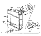
米国特許出願第08/454,975号は、連続補充を行なうようになっている負圧およびばね袋印字カートリッジについて述べている。図4〜図8は、米国特許出願第08/454,975号に述べられているのと同様であるが、印字カートリッジ70〜76の握り把手に自己シール補充ポートを追加することにより周期補充するようになっているインクジェット印字カートリッジ100を示す。インクジェット印字カートリッジ100は、図1のインク分配システムの印字カートリッジ70〜76を示している。インクジェット印字カートリッジ100は、インクを貯蔵する内部貯蔵容器104を囲むハウジング102を備えている。インクジェットノズルの付いた印字ヘッド106は、ハウジング102に取付けられている。印字ヘッド106は、内部貯蔵容器104からインクを受取り、印刷動作中印字カートリッジ70〜76が印字キャリッジに沿って前後に走査している間にインク小滴を放出する。突出握り(protruding grip)108が ハウジング102から突出してインクジェットプリンタの印字カートリッジ70〜76に対する便利な設置および取り外しを可能にしている。
【0018】
図5〜図8は、突出握り108の別の詳細図を示す。突出握り108は、内部貯蔵容器104と連通している円筒形の補給ポート114の対向側面に二つのコネクタ110、112を備えている。円筒形の補給ポート114は、エラストマ材料から形成された隔壁であるポート116によりシールされている。ポート116には小さい開口118が形成されている。その円筒形の補給ポート114を有する突出握り108は、中空の管状の針122により図1のシステムのキャリッジ外インク貯蔵容器80〜86の一つに接続されているバルブ構造120と周期的に係合するように設計されている。図5は、ポート116に隣接しているが係合はしていないバルブ構造120を示す。図6は、ポート116と完全に係合しているバルブ構造120を示す。図6に示すように、バルブ構造120は、閉じた遠端を有するが、端に隣接して複数の開口が形成されている針122を備えている。滑りバルブ加湿器128が針122の周りに堅く取付けられ、ばね126により図5に示すバルブ閉位置に片寄せられている。バルブ構造120がポート116の方に押されると、滑りバルブ加湿器128が針122の長さ押し上げられ、図6に示すように、針122の先端をポート開口118の中に滑入させる。この位置で、インクは、針開口124を通って内部貯蔵容器104と補充管130との間を流れることができる。従って、インクジェット印字カートリッジ100がバルブ構造120のような構造を介してキャリッジ外インク貯蔵容器80〜86に接続された状態で、印字カートリッジ70〜76とキャリッジ外インク貯蔵容器80〜86との間に流体経路が確定される。インクは、キャリッジ外インク貯蔵容器80〜86と内部貯蔵容器104との間を流れることができる。バルブ構造120が突出握り108から向こうに引かれると、バルブ構造120は、滑りバルブ加湿器128に作用するばね126のため自動的に閉じる。ポート開口118は、ポート116の材料の弾性により同様に閉じ、それにより印字カートリッジ70〜76に対して自己シール補充ポートを与える。図4〜図8は、バルブ構造120を補充腕ソケット174にあるバルブ保持器腕170に解放可能にロックするロック構造172を示す。ロック構造172は、バルブ本体120Aの外部ハウジングに係合するロッキング面172Bを備えている(図5)。ロック構造172は組み込みばね部材172Aによりロック位置に片寄せられている(図7および図8)。点170C(図7および図8)でロック構造172に力を加えることにより、ばね126が圧縮され、ロッキング面172Bを移動させてバルブ本体120Aとの係合から外し、バルブを補充腕ソケット174の外に引っ張る。このロック構造172の解放によりバルブおよび内部貯蔵容器104をユニットとして急速に交換することができる。
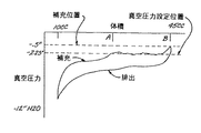
【0019】
印字カートリッジ70〜76は各々、米国特許出願第08/454,975号に更に詳細に説明されている、負圧ばね袋インク分配システムを利用する単独室本体を備えている。印字カートリッジ70〜76のインク排出背圧曲線はヒステリシスを示す。図9は、図1のシステムに採用されている印字カートリッジに対する典型的な真空圧力−インク体積曲線を示す。インク排出背圧曲線は、インク補充背圧曲線とは異なること、およびインク補充背圧曲線には幾つかの相対的ピークまたは「隆起」があることがわかる。キャリッジ外インク貯蔵容器80〜86に補充中印字カートリッジ70〜76に対して一定高さに保持し(すなわち、補給ポート114をバルブ構造120に接続し)、印刷に適確な真空圧力を与えると、非常にあり得る状態は印字カートリッジ70〜76が、図9に示すインク補充背圧曲線でAで示した小さい体積にだけしか充填されないことである。
【0020】
本発明によれば、キャリッジ外インク貯蔵容器80〜86は高さ可変な補充プラットフォーム150に設置され、これによりキャリッジ外インク貯蔵容器80〜86を上位置、「補充」位置、カートリッジ印字ヘッドノズルより1インチ未満下、に設置することができる。この位置で、その高さ位置のためキャリッジ外インク貯蔵容器80〜86における圧力水頭が増大している状態で、印字カートリッジ70〜76の内部貯蔵容器104は、図9の補充曲線のBで示した大きい体積に充填される。このため、印字カートリッジ70〜76の真空圧力は、高印刷品質を与えるには低すぎ、キャリッジ外インク貯蔵容器80〜86の位置は、その後印字ヘッドノズルに対して下がり、少量のインク、例えば、例示された実施形態では約1〜3ccのインクが印字カートリッジ70〜76の内部貯蔵容器104から補充管130を通って、キャリッジ外インク貯蔵容器80〜86に逆に流入して、真空圧力を図9のインク排出背圧曲線に沿う適切な範囲に流れることができるようになる。次に、バルブ構造120をポート116から切り離すことができ、印刷システムがインクが補充された印字カートリッジで印刷を進めることができる。
【0021】
内部貯蔵容器104の出力ポートで供給される圧力水頭も、袋の中のインクの体積が消耗されるにつれて変化する。図10は、例示された内部貯蔵容器104の袋に対する関係を示す。インクの体積が消耗するにつれて、圧力が減少する。この圧力減少は、インクの流れの割合がインクの体積が減少するにつれて減少するから、補充印字カートリッジに別の問題を提示する。高さ可変な補充プラットフォーム150が印字ヘッドノズルに対して袋を高く移動させて圧力水頭を増大させ、インクを印字カートリッジ70〜76に流入させる圧力差を極大にすることにより、この問題をよく処理し、各印字カートリッジ70〜76の内部貯蔵容器104の袋を究極的にインクを確実に消耗させることができる。
【0022】
本発明による補充プラットフォーム150の目的は、図9のヒステリシス曲線を用いて印字キャリッジ70〜76搭載の内部貯蔵容器104の最適補充を与えるために、すなわち、印字カートリッジ70〜76に大量のインクを少ない時間で補充するために、全てのキャリッジ外インク貯蔵容器80〜86を上下に移動させることである。
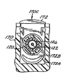
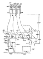
【0023】
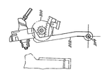
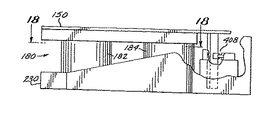
図1に例示されたシステムでは、補充プラットフォーム150は、図2に示すように、感熱式インクジェット大型プリンタ/プロッタ50の左ハウジング56の中にある。120度の間隔で設置されている3個のカム182、184、186を有するカムシステム180が補充プラットフォーム150を昇降させるのに採用されている。プラットフォームモータ188が歯車列190を駆動してカムシステムを作動させる。
【0024】
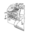
4個のキャリッジ外インク貯蔵容器80〜86が補充プラットフォーム150に支持されている。短い柔軟管152、154、156、158が対応するキャリッジ外インク貯蔵容器80〜86のポート80A、82A、84A、86Aとバルブ保持器腕170で支持されている遮断バルブ160〜166との間に接続されている。これら遮断バルブ160〜166は各々、図4〜図8のバルブ構造120に対応する。
【0025】
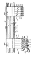
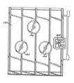
補充プラットフォーム150は、4個のキャリッジ外インク貯蔵容器80〜86を保持し、プロットフォーム188により上下に移動できる昇降機である。補充プラットフォーム150には図11に示すように三つの安定位置がある。上位置Pup、すなわち、最高高さ位置は印字カートリッジ70〜76を過剰補充するのに使用される。印字カートリッジ70〜76に補充する必要があるごとに、キャリッジ外インク貯蔵容器80〜86をこの位置に上昇させ、補充時間中そこに保持する。この位置の目的は、印字カートリッジ70〜76内の背圧を(内部貯蔵容器104の中のインクの量に応じ)水柱−0.5"と水柱−2.5"との間に平衡させ、各印字カートリッジ70〜76が可能な限り多量のインクを飲むことができるようにすることである。各印字カートリッジ70〜76は、既に消費したインクの量、すなわち、キャリッジ外インク貯蔵容器80〜86に残っているインクの量により異なる量のインクを飲むことになる。
【0026】
補充プラットフォーム150の下位置Pdownは安定位置であり、印字カートリッジ70〜76の内部貯蔵容器104の内側の圧力は、ほぼキャリッジ外インク貯蔵容器80〜86が下に移動した距離だけ減少している。
【0027】
印字カートリッジ70〜76の内部貯蔵容器104の内側の圧力は、印字ヘッドノズルと補充プラットフォーム150、すなわちキャリッジ外インク貯蔵容器80〜86の底部、との間の偏り(負)距離にキャリッジ外インク貯蔵容器80〜86の圧力の量を加えたものに等しい値に安定している。例えば、補充プラットフォーム150が上位置Pupにあるとき、オフセット距離は−2.25インチである。キャリッジ外インク貯蔵容器80〜86が貯蔵容器充填ポートで+0.5インチ(水柱のインチで表して)の出口圧力を与える体積にあると想像しよう。充填されたとき印字カートリッジのキャリッジ外インク貯蔵容器80〜86の中の圧力は、−2.25インチ+0.5インチ=−1.75インチ(全て水柱のインチで表して)になる。さて、安定化期間中、キャリッジ外インク貯蔵容器80〜86および補充プラットフォーム150は、印字ヘッドノズルより4インチ下の、例示された実施形態ではPup位置より1.75インチ下の、Pdown位置まで下降する。この移動により印字カートリッジ70〜76の真空圧力が−1.75インチだけ効果的に変化するので、真空圧力は、−1.75インチ−1.75インチ=−3.5インチ(水柱のインチで表して)の真空圧力になる。
【0028】
補充プラットフォーム150の中間位置Pparkは、キャリッジ外インク貯蔵容器80〜86を装着および取り外しするのに使用され、駐機位置である。
【0029】
カートリッジの補給ポート114と係合しているバルブ構造120により補充している間の背圧は(水柱のインチで表して)、−0.5インチより大きく、−2.5インチより小さい。補充後の背圧は−2.25インチより大きく、−4インチより小さい。印刷動作中、背圧は(水柱の)−2インチより大きく、インクが印字カートリッジ70〜76の内部貯蔵容器104から消耗するにつれて、水柱の約−8乃至−9インチに近づく。
【0030】
上位置Pupで2分後、補充プラットフォーム150は、キャリッジ外インク貯蔵容器80〜86を印字ヘッド106より4インチ下の下位置まで下げてカートリッジ内の背圧を動作範囲に設定し、キャリッジ外インク貯蔵容器80〜86をこの下位置Pdownに約15分間保持する。背圧はカートリッジ内で減少するが、内部貯蔵容器104の中のインクの体積は、わずかしか減少しない。なぜならば、圧力は背圧曲線の疑似垂直域で移動しているからである。
【0031】
その後、印字カートリッジ70〜76は補充ステーションバルブから切り離され、補充プラットフォーム150は中間位置Pparkに移動し、次の補充または交換に常に応じ得る態勢になっている。
【0032】
補充を行なうには、キャリッジ組立体60を4個のキャリッジ外インク貯蔵容器80〜86が遮断バルブ160〜166を介して対応する印字カートリッジ70〜76に接続されている補充ステーションに移動させる。上に引用したMaxS. Gunther他の「印字ヘッドの定期的インク補給のための単一オンオフ制御バルブを用いる印刷システム」は、遮断バルブの別の詳細を示している。この目的に適する遮断バルブの他の形態は、上に引用したRobert J.Katon他の「インクジェットカートリッジの充填ポートアダプタ」に記されている。内部貯蔵容器104の接続は、図3および図12〜図13に示すように、バルブ構造120およびバルブ保持器腕170が取付けられているレバー202を前進させるステッパモータ200を回転することにより行なわれる。バルブをポートに係合および解放するようバルブを動かすのに適したシステムは、Ignacio Olazabal他の「インク供給バルブを多数印字ヘッドと定期的に自動接続する装置」に完全に説明されている。バルブ構造120はインクジェット印字カートリッジ100の補給ポート114に係合するが、インクは、わずかな真空圧力(背圧)のため印字カートリッジ70〜76の内部貯蔵容器104に引き込まれる。この背圧はインク体積の増大とともに減少することが知られている。この結果、更に多量のインクが印字カートリッジ70〜76に導入されるにつれて、背圧が印字カートリッジ70〜76がもはやカートリッジから追加インクを引くことができない点まで減少して補充が停止する自己調整補充プロセスを生ずる。インクの流れが停止する圧力は、印字カートリッジ70〜76およびキャリッジ外インク貯蔵容器80〜86を片寄せる(offset)距離により支配される。キャリッジ外インク貯蔵容器80〜86の位置が印字カートリッジ70〜76より低くなればなるほど、印字カートリッジ70〜76の最終真空圧力は大きくなり、印字カートリッジ70〜76内の内部貯蔵容器104内のインクの体積は減少する。
【0033】
背圧−インク体積曲線は、印字カートリッジごとに異なる。このため補充体積に大きな変動を生ずる可能性がある。この変動を除去するために、印字カートリッジ70〜76とキャリッジ外インク貯蔵容器80〜86との間の距離を積極的に制御する。補充プロセスの始めに、キャリッジ外インク貯蔵容器80〜86を印字カートリッジ70〜76の非常に近くに設置すると、インクは印字カートリッジ70〜76内に比較的急速に移動する。この高い位置では、得られる背圧は、良好な印刷品質を確保するには低すぎる。それでキャリッジ外インク貯蔵容器80〜86を下げることにより背圧を印刷可能範囲内にあるように設定すると、少量のインクが印字カートリッジ70〜76から逆にキャリッジ外インク貯蔵容器80〜86に戻り、従って背圧が増大する。印字カートリッジ70〜76に過充填し、次に少量のインクを除去することにより、全ての印字カートリッジ70〜76に対する充填完了時体積があまり変わり得なくなる。
【0034】
補充動作のシーケンス全体を比較的急速に行なうことができる。補充プロセスに対する代表的所要時間は、次のとおりである。キャリッジを補充ステーションまで移動…5秒、バルブを印字カートリッジ70〜76の再充填ポートに係合させる…15秒、Pupの補充プラットフォーム150で充填する時間を待つ…120秒、補充プラットフォーム150をPdownまで下降させる…15秒、バルブを解放する…10秒。以上から、例示された実施形態に対する補充動作の全予想時間として180秒が得られた。これは補充に対して比較的短い時間である。他の長所は、印字カートリッジ70〜76をキャリッジから取り外したり交換したりせずに補充を行なうことができ、従って、補充プロセスの効率に更に寄与するということである。更に他の長所は、印字カートリッジ70〜76が全て、補充プロセス中、印字カートリッジ70〜76をキャリッジから取り外さずに、同時にインクを補給されるということである。
【0035】
本発明による補充技術の他の特徴は、インク補給の途中でインクレベルを検出する必要がないということである。補充プラットフォーム150はPup設置される、すなわち必要な圧力水頭を与えて印字カートリッジ70〜76の内部貯蔵容器104に補充する位置に所定の時間に単に設置されるだけであり、この期間が満了後、カートリッジは確実に充填されている。
【0036】
補充シーケンスは下記のようにして始められる。この例示された補充システムの実施形態の目標は、補充の終わりに各キャリッジ搭載の印字カートリッジ70〜76の内部貯蔵容器104の中の分配可能なインクの少なくとも18ccを得ることである。この目標が満たされると仮定すると、印刷後に印字カートリッジ70〜76内にあるインクの量を、最近の補充以来発射されたインク滴の数を数えてインク滴の数を消費されたインク体積に関連付けることにより決定することができる。これは、キャリッジ搭載のカートリッジの印字ヘッド106から発射された全てのインク滴が統計的に最悪の場合の大きいサイズであると仮定し、この最悪の場合のサイズを使用して消費されたインク体積の推定値を計算することにより行なうことができる。補充システムの他の目標は、ユーザが最悪の場合の100%の範囲の、すなわち100%の濃いEサイズの印刷を確実に完了することができることである。この印刷に必要なインクの体積は、概略11.5ccである。従って、計算した印字カートリッジ70〜76のインク体積が11.5ccより下がったとき補充を始めることができる。代わりに、インク滴の体積を実際の印刷状態に基づいて、例えば、特定の印刷モードおよび実際のインク滴体積に影響する他の因子を考慮し、次に消費したインク体積の全体量を保持することにより、予測することができる。補充をカートリッジ内の推定残存インク体積に達したときに始めるのではなく、予測した消費インク体積がある値、例えば4ccを超えたとき始めることができる。
【0037】
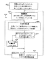
システムの動作シーケンス300を一般に図14に示す。ステップ302で、カートリッジ、印字ヘッド106およびヘッドクリーナセットのインストール後直ちに、制御装置はこのIDSにより使用された全インクに対するパラメータ数を0にリセットする。ステップ304で、補充動作を行い、最近の補充以来使用された現在のインク体積に対するパラメータを全ての色について0にリセットする。これによりキャリッジ搭載の印字カートリッジ70〜76が既知のインクレベルになる。このことは、全ての印字カートリッジ70〜76が印字ヘッド106に分配可能インクの18.5ccの補充後最小使用可能インク(MUIAR)目標体積より上にあるべきことを意味する。
【0038】
ステップ306で、システムは、所要画像を印刷し、制御装置は、各色について使用された全インク体積、および使用された現在のインク体積に対するパラメータ値を増加させる。
【0039】
ステップ308は、印刷作業が完了してから行なわれ、使用された全インクに対するパラメータを全ての印字ヘッドに利用し得る最大インクに対する所定閾値と比較する試験である。全てのIDSに対して使用された全インク体積が閾値を超えていれば、ユーザは、ステップ310で、通常は前パネルのメッセージにより、低インク状態の警告を受ける。動作は、ステップ312に進む。ここで、他の試験が行なわれる。
【0040】
ステップ312で使用されたインクの現在の量に基づき補充が始められる。図示した例示された実施形態では、印字カートリッジ70〜76により最近の補充以来消費された、インク滴計数により決定されたインクの量が、補充開始体積を超えていれば、補充が始められる。
【0041】
補充シーケンスが完了してから、補充プラットフォーム150は、駐機位置に移動する。他の補充シーケンスが始まり、バルブが印字カートリッジの補給ポート114に接続されてから、補充プラットフォーム150は、上位置に上昇する。
【0042】
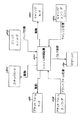
図15は、システム制御装置400、駆動機構および制御システムの種々の要素を示す簡略機能ブロック図である。システム制御装置400は、発射インパルスを印字ヘッド106の発射室抵抗器に与え、各色について発射されたインク滴の数を数える。システム制御装置400はステッパを駆動するキャリッジモータ404を制御し、キャリッジエンコーダセンサ406からキャリッジ位置データを受け取る。プラットフォームモータ188およびステッパモータ200に発し、プラットフォームエンコーダ408およびステッパエンコーダ402から補充プラットフォーム150およびバルブの位置データを受け取る。
【0043】
図16〜図20は、補充プラットフォーム150および昇降機構造を更に詳細に示している。補充プラットフォーム150を上下させるのに、120度離して設置された3個のカム182、184、186を有するカムシステム180を採用している。プラットフォームモータ188が歯車列190を駆動してカムシステムを作動させる。補充ステーション板230がカムシステム180およびプラットフォームモータ188を支持している。補充ステーション板230は、3個の上向きに突出する中空円筒ボス232、234、236を備えている。図19および図20は、中空円筒ボス232および対応するカム182を示している。補充プラットフォーム150はまた、遠端から突出するカム面150B、150Cを有する、下向きに突出する円筒ボス150Aを形成している。カム面150B、150Cは、カム182により形成されるスロット182C(図11)に乗っている。カム182は、上部部材182Aおよび下部部材182Bにより形成され、下部部材182Bは歯車182Dをも形成している。プラットフォームモータ188が回転するにつれて、歯車182Dも回転し、カム面150B、150Cをスロット182Cに追随させる。上位置Pupおよび下位置Pdownは、スロット182Cの先端により形成されている(図11)。駐機位置(Ppark)は、スロットの先端間の中間に形成されたジョグである歯車182Dにより設定されている。
【0044】
補充機構は、感熱式インクジェット大型プリンタ/プロッタ50の始動中、関心を与える。補充中不注意にパワーが遮断され、バルブがなお印字ヘッド106に係合していると想像しよう。バルブが印字カートリッジ70〜76に長時間係合していると仮定することは賢明である。これは、始動し初期設定されても、バルブがなお係合しており、重大な損傷を生ずることがあるので、キャリッジは直ちに移動することができないということを意味している。その他、機械がバルブと長時間係合し且つ補充プラットフォーム150が下降していないので、印字カートリッジ70〜76が非常に一杯であると仮定されるから、補充プラットフォーム150を下に移動して、インクを除去し、印字ヘッドの背圧を設定することにより、補充サイクルを完了する必要がある。従って、始動中、(1)補充プラットフォーム150を下位置に移動させて背圧を設定し、(2)次にバルブを解放する。最後に、補充操作を行なって印字カートリッジが健全であることを確認すべきである。
【0045】
上述の実施形態は、本発明の原理を表す可能な特定の実施例の単なる例示であることが理解される。当業者は、本発明の範囲および精神を逸脱することなく、これら原理に従って他の装置を容易に工夫できるであろう。
【0046】
以下に本発明の実施の形態を要約する。
1. プリンタ/プロッタのキャリッジに搭載の印字カートリッジで液体インク供給品を周期的に補給するインク補給可変圧力制御方法であって、可動キャリッジ(60)上にインク供給品を負圧下で保持する内部貯蔵容器(104)を備えたインクジェット式の印字カートリッジ(100)を設けるステップと、インク供給品を前記内部貯蔵容器(104)に供給するステップと、前記印字カートリッジ(100)の前記内部貯蔵容器(104)に周期的に接続するのに利用できるキャリッジ外インク供給源(80)を準備するステップと、前記キャリッジ外インク供給源(80)と前記印字カートリッジ(100)の前記内部貯蔵容器(104)との間にインク流路(120、122)を確定するステップと、前記キャリッジ外インク供給源(80)に前記キャリッジ外インク供給源(80)から前記印字カートリッジ(100)の前記内部貯蔵容器(104)までインクを流し、インクを前記キャリッジ外インク供給源(80)から前記印字カートリッジ(100)の前記内部貯蔵容器(104)に流入させ、前記インク供給品を前記内部貯蔵容器(104)に補給するのに十分なインク圧力水頭を確定するステップと、前記内部貯蔵容器(104)の内部に負圧を保持しながら前記インク流路(120、122)を前記印字カートリッジ(100)の前記内部貯蔵容器(104)から切り離すステップと、から成るインク補給可変圧力制御方法。
【0047】
2. 更に、前記インク供給品を前記印字カートリッジ(100)の前記内部貯蔵容器(104)に補給してから、前記インク流路(120、122)を切り離す前に、有効な前記インク圧力水頭を下げて少量のインクを前記印字カートリッジ(100)の前記内部貯蔵容器(104)から前記キャリッジ外インク供給源(80)に流入させ、前記内部貯蔵容器(104)内の負圧を適切な圧力に設定して高い印字品質を確保するステップ、を備えている上記1記載のインク補給可変圧力制御方法。
【0048】
3. 更に、前記インク流路(120、122)は閉流路である上記1または2に記載のインク補給可変圧力制御方法。
【0049】
4. 更に、前記インク圧力水頭を確定する前記ステップは、前記キャリッジ外インク供給源(80)から前記印字カートリッジ(100)の前記内部貯蔵容器(104)にインクを流入させるのに十分な前記インク圧力水頭を与える高さに前記キャリッジ外インク供給源(80)の容器を設置することから成る上記1〜3のいずれかに記載のインク補給可変圧力制御方法。
【0050】
5. 更に、前記インク流路(120、122)を確定する前記ステップ、前記インク圧力水頭を確定する前記ステップ、およびインクを前記キャリッジ外インク供給源(80)から前記印字カートリッジ(100)の前記内部貯蔵容器(104)に流入させて前記内部貯蔵容器(104)に前記インク供給品を補給する前記ステップは、前記印字カートリッジ(100)を前記キャリッジから取り外さずに行なわれる上記1〜4のいずれかに記載のインク補給可変圧力制御方法。
【0051】
6. 更に、インクを流す前記ステップは所定の時間だけ行なわれる上記1〜5のいずれかに記載のインク補給可変圧力制御方法。
【0052】
7. 更に、インクを流す前記ステップはインクのレベルを検出することなく行なわれる上記6に記載のインク補給可変圧力制御方法。
【0053】
8. 更に、複数のインクジェットカートリッジ(70、72、74、76)が前記可動キャリッジ(60)に設けられ、前記インクジェットカートリッジ(70、72、74、76)のそれぞれは異なる色のインク供給品を負圧下に保持し、対応する内部貯蔵容器(104)を備え、前記インク供給品が前記内部貯蔵容器(104)のそれぞれに供給され、対応するキャリッジ外インク供給源(80、82、84、86)が前記印字カートリッジ(100)のそれぞれに設けられており、前記インク流路を確定する前記ステップは、前記印字カートリッジ(100)のそれぞれとこれに対応する前記キャリッジ外インク供給源(80、82、84、86)との間に対応するインク流路を確定することから成り、前記インク圧力水頭を確定してインクを流す前記ステップは、前記キャリッジ外インク供給源(80、82、84、86)について前記インク圧力水頭を確定し、インクを対応する前記キャリッジ外インク供給品(80、82、84、86)の貯蔵容器から前記印字カートリッジ(100)の前記内部貯蔵容器(104)のそれぞれに流入させて前記内部貯蔵容器(104)のそれぞれにインク供給品を補給することから成る上記1〜7のいずれかに記載のインク補給可変圧力制御方法。
【0054】
9. 更に、前記印字カートリッジ(100)を使用してインクを印字ヘッドから放出し記録媒体上に画像を印刷するステップと、前記可動キャリッジ(60)を移動させ前記印字カートリッジ(100)を補充ステーションに位置決めするステップと、を備えており、前記インク流路(120、122)を確定する前記ステップ、前記インク圧力水頭を確定する前記ステップ、前記インク圧力水頭を下げる前記ステップ、および前記インク流路(120、122)を切り離す前記ステップは、前記印字カートリッジ(100)を補充ステーションに置いて行なわれる上記2に記載のインク補給可変圧力制御方法。
【0055】
10. 更に、前記インク圧力水頭を上げる前記ステップは前記キャリッジ外インク供給源(80)を第1の高さに位置決めすることから成り、前記インク圧力水頭を下げる前記ステップは前記キャリッジ外インク供給源(80)を前記第1の高さより低い第2の高さに位置決めすることから成る上記9に記載のインク補給可変圧力制御方法。
【0056】
11. 前記インク流路(120、122)を確定する前記ステップはバルブ構造(120)を前記印字カートリッジ(100)のインク補給ポート(114)に接続することから成り、前記インク流路(120、122)を切り離す前記ステップは前記バルブ構造(120)を前記インク補給ポート(114)から切り離すことから成る上記9または10に記載のインク補給可変圧力制御方法。
【0057】
12. 負圧インクジェット印字カートリッジを使用するプリンタ/プロッタシステム(50)であって、
液体インク供給品を負圧下で保持する内部貯蔵容器(104)を有し、インク補給ポート(114)を備えているインクジェット式の印字カートリッジ(100)と、
前記内部貯蔵容器(104)にあるインク補給品と、
印字カートリッジ(60)を保持するキャリッジと、
前記キャリッジをキャリッジ走査軸の方向に駆動するキャリッジ走査装置(96、404)と、
キャリッジ外インク供給源(80)と、
インク補給ステーションで前記キャリッジ外インク供給源(80)と前記キャリッジの前記インク補給ポート(114)との間に流体経路を周期的に接続するバルブ装置(120)と、
前記キャリッジ外インク供給源(80)を支持するプラットフォーム構造(150)と、
前記プラットフォーム構造(150)を昇降させて前記キャリッジ外インク供給源(80)を前記バルブ装置(120)が接続されている間に第1の高さ位置に位置決めし、前記バルブ装置(120)が接続されている間に第2の高さ位置に位置決めする装置(188)と、を備えているプリンタ/プロッタシステム(50)。
【0058】
【発明の効果】
上述のように本発明のインク補給可変圧力制御方法およびプリンタ/プロッタシステムによれば、インクの補充を比較的短時間で実行でき、印字カートリッジをキャリッジから取り外したり交換したりせずに補充を行なうことができる。また、インクの補給の途中でインクレベルを検出する必要がない。
【図面の簡単な説明】
【図1】本発明に係る大型プリンタ/プロッタシステムを示す等角図である。
【図2】図1の大型プリンタ/プロッタシステムの一部の拡大図であり、補充ステーションを示す図である。
【図3】プリンタキャリッジおよび補充ステーションを示す上面図である。
【図4】補充腕部、針バルブ、および供給管を分解して示した、図1の大型プリンタ/プロッタシステムに使用できるインクジェット印字カートリッジを示す等角図である。
【図5】図4の線5−5で切った断面図であり、印字カートリッジの補充ポートに対して解放位置にあるバルブ構造を示す図である。
【図6】図5と同様の断面図であるが、印字カートリッジの補充ポートに対して係合位置にあるバルブ構造を示す図である。
【図7】図6の線7−7で切った断面図であり、針弁の構造および補充ステーションにおいて補充腕ソケットにあるバルブをロックするロック構造を示す図である。
【図8】図7と同様の断面図であり、解放位置におけるロックを示す図である。
【図9】インク排出(印刷)および補充の期間中の、ペンの真空圧力を、例示印字カートリッジの内部貯蔵容器の中のインクの体積の関数として示す図である。
【図10】例示キャリッジ外インク貯蔵容器袋の内部の圧力を袋の中のインクの体積の関数として示す図である。
【図11】インク補充ステーションの要素を示す、インク貯蔵容器プラットフォームが色々な高さにある状態の簡略された前部平面図である。
【図12】補充ステーションにおいてバルブ構造を印字カートリッジ充填ポートに対して係合および解放する機構を簡略側面図で示している。解放位置にあるバルブ構造を示す図である。
【図13】補充ステーションにおいてバルブ構造を印字カートリッジ充填ポートに対して係合および解放する機構を簡略側面図で示している。係合位置に移動したバルブ構造を示す図である。
【図14】印字カートリッジに周期的に補充する際の図1の印刷システムの動作を示す簡略フローチャートである。
【図15】図1の印刷システムのシステム制御装置および制御要素の機能ブロック図である。
【図16】補充プラットフォームを示す部分破断上面図である。
【図17】図16のプラットフォームを示す側面図である。
【図18】図17の線18−18で切った断面図である。
【図19】図18の線19−19で切った断面図である。
【図20】図20の線20−20で切った断面図である。
【符号の説明】
50 感熱式インクジェット大型プリンタ/プロッタ
60 キャリッジ組立体
80〜86 キャリッジ外インク貯蔵容器
100 インクジェット印字カートリッジ
104 内部貯蔵容器
114 補給ポート
120、122 インク流路
150 補充プラットフォーム[0001]
BACKGROUND OF THE INVENTION
The present invention relates to an ink jet printer and / or an ink jet plotter, and in particular, changes the height of an off-axis ink cartridge storage container to reduce the refill time of a carriage-mounted print cartridge and increase the ink refill volume reliability. The present invention relates to a technique for securing and setting the vacuum pressure of a print cartridge.
[0002]
[Prior art]
The printing system is described in a commonly assigned patent application entitled “Method of Continuously Refilling Inkjet Swash Printer / Plotter Spring Bag Ink Storage Container”. This employs a non-carriage ink reservoir connected to the carriage-mounted print cartridge by a bendable tube. The ink storage container outside the carriage continuously replenishes the ink supply in the internal storage container of the on-carriage print cartridge and maintains the back pressure within the range where high quality printing occurs. While this system has many advantages, there are some applications in which it is not desirable to have a relatively permanent connection of the off-carriage ink reservoir and the carriage-mounted reservoir with a tube.
[0003]
A new ink distribution system (IDS) for printers / plotters has been developed, according to which the print cartridge carriage-mounted spring reservoir is simply periodically connected to the off-carriage ink reservoir to “instantly fill ink ( take a gulp) and then separated from the ink storage container outside the carriage. A tube for permanently connecting the carriage mounting element and the carriage outer element is not required. Related applications referred to above, “Space Efficient Envelope Shape for Incorporating Multiple Replaceable Ink Supply Bags”, “Printing with Single On / Off Control Valve for Periodic Ink Refill of Print Head "System" and "Apparatus for periodic automatic connection of ink supply valves with parallel printheads" describe certain parts of the dispensing system of the present invention.
[0004]
The present invention optimizes this take-a-gulp ink dispensing system with this new off-carriage. In this type of IDS, a print cartridge that applies a vacuum pressure using an internal spring is periodically connected to an ink storage container installed off the carriage scanning axis. Starting with a “full” print cartridge, the printer / plotter prints various drawings while monitoring the amount of ink used. After the specified amount of ink has been dispensed, the carriage moves to the refill station for ink replenishment. At this refill station, the valve is engaged with the print cartridge, the ink reservoir is connected to the print cartridge, and the path for free flow of ink is opened. Ink is drawn from the storage container into the print cartridge using only the vacuum pressure present in the print cartridge.
[0005]
[Problems to be solved by the invention]
The vacuum pressure of the print cartridge varies with the amount of ink contained in the print cartridge. Usually, a low ink volume is associated with a high vacuum pressure and a high ink volume is associated with a low vacuum pressure. The vacuum pressure-ink volume curve shows hysteresis, and for a given ink volume, there is a different vacuum pressure in the print cartridge than when refilling (increasing ink volume) during printing (ink volume decreasing). Arise. In addition, the refill vacuum pressure curve has several relative peaks or “ridges” whereby several ink volumes produce the same vacuum pressure. This is because in this type of self-regulating refill system, the flow of ink to the print cartridge stops when the vacuum pressure in the print cartridge is equal to the distance that the ink reservoir is offset under the print cartridge. Presents a serious problem. Thus, for a given offset distance, the print cartridge is always refilled to a minimum volume that produces a pressure equal to the offset distance. These minimum “tight” refill volumes are unpredictable and often very small (approximately half the print cartridge storage container volume), which is undesirable.
[0006]
[Means for Solving the Problems]
To avoid this underfilling problem, the position of the storage container is actively moved up and down by vertical movement. After the valve is engaged with the print cartridge, the storage container is placed in close proximity to the print cartridge (the top of the ink storage container is approximately ½ ″ below the nozzle of the print cartridge). In position, the offset distance is small enough that the ink will continue to flow into the print cartridge regardless of the presence or magnitude of the pressure-volume curve bulges. In this position, however, the print cartridge is overfilled, in which case the vacuum pressure in the print cartridge reservoir is too small to ensure high print quality. To get within the proper range, lowering the storage container causes a small amount of ink to flow back into the storage container. It increases in the switching range.
[0007]
These and other features and advantages of the present invention will become more apparent from the following detailed description of the illustrated embodiments, as illustrated in the drawings.
[0008]
The present invention also relates to US patent application Ser. No. 08 / 454,975, filed May 31, 1995, Joseph E. et al. A modification of Scheffelin et al.'S "Continuous replenishment of spring bag storage in inkjet swath printer / plotter". The relevant overall contents are described in this US patent application Ser. No. 08 / 454,975.
[0009]
US patent application Ser. No. 08 / 454,975 is also related to: Erich Coiner et al., “Space Efficient Envelope Shape for Incorporating Multiple Replaceable Ink Supply Bags”, Max. Gunther et al. “Printing system with single on / off control valve for periodic ink replenishment of print heads”, Ignacio Olazabal et al. “Apparatus for periodic automatic connection of ink supply valves with parallel print heads”. Robert J .; Katon et al. "Inkjet Cartridge Filling Port Adapter".
[0010]
DETAILED DESCRIPTION OF THE INVENTION
An embodiment of the present invention is a swath plotter / printer for large printing (LFP). FIG. 1 is a perspective view of a thermal ink jet large size printer / plotter 50. The thermal inkjet large printer / plotter 50 includes a
[0011]
FIG. 3 is a top view of the carriage assembly 60 and the refill station. The carriage assembly 60 slides on the slide bars 94A and 94B. The position of the carriage assembly 60 along the horizontal axis or carriage scan axis is determined by the carriage positioning mechanism with respect to the
[0012]
The thermal ink jet large size printer / plotter 50 includes four print cartridges 70-76 in the internal spring bag ink storage container for storing different colors, for example, black, yellow, magenta and cyan ink, respectively. When the carriage assembly 60 is translated relative to the medium in the y-axis direction, a predetermined nozzle of the inkjet cartridge is activated and ink is added to the medium.
[0013]
The carriage assembly 60 holds circuits necessary for positioning the
[0014]
As described above, for all color printing and drawing, it is necessary to add the color from the individual print cartridge to the medium. As a result, the ink is consumed from the
[0015]
The correct location of each component is preferably distinguished by color. If the color of the replacement component matches the color of the frame that receives the component, the correct position of the component is ensured. All three components are in the same order, and in the illustrated embodiment, the yellow component is in the leftmost position, the cyan component is in the center left position, and the magenta component is in the center right position. And the black component is in the rightmost position.
[0016]
The ink dispensing system is an instantaneous filling ink replenishment system. The system replenishes all four print cartridges 70-76 simultaneously when any one of the ink volumes in the
[0017]
US patent application Ser. No. 08 / 454,975 describes a negative pressure and spring bag print cartridge adapted for continuous refilling. 4-8 are similar to those described in US patent application Ser. No. 08 / 454,975, but are refilled periodically by adding a self-seal refill port to the grip of print cartridges 70-76. An
[0018]
5-8 show another detailed view of the protruding
[0019]
Each of the print cartridges 70-76 includes a single chamber body utilizing a negative pressure spring bag ink dispensing system, which is described in further detail in US patent application Ser. No. 08 / 454,975. The ink discharge back pressure curve of the
[0020]
According to the present invention, the
[0021]
Supplied at the output port of the
[0022]
The purpose of the
[0023]
In the system illustrated in FIG. 1, the
[0024]
Four off-carriage ink storage containers 80-86 are supported on the
[0025]
The
[0026]
The lower position Pdown of the
[0027]
The pressure inside the
[0028]
The intermediate position Ppark of the
[0029]
The back pressure (expressed in inches of water column) during refilling by the
[0030]
After 2 minutes at the upper position Pup, the
[0031]
Thereafter, the print cartridges 70-76 are disconnected from the refill station valve, and the
[0032]
To perform refilling, the carriage assembly 60 is moved to a refilling station in which four out-carriage ink reservoirs 80-86 are connected to corresponding print cartridges 70-76 via shutoff valves 160-166. MaxS. Cited above. Gunther et al., "Printing System with a Single On / Off Control Valve for Periodic Inking of the Printhead" shows another detail of the shutoff valve. Another form of shut-off valve suitable for this purpose is Robert J., cited above. Katon et al., “Inkjet Cartridge Fill Port Adapter”. The
[0033]
The back pressure-ink volume curve is different for each print cartridge. This can cause large fluctuations in the replenishment volume. In order to eliminate this variation, the distance between the
[0034]
The entire sequence of replenishment operations can be performed relatively quickly. A typical duration for the replenishment process is as follows: Move the carriage to the refill station ... 5 seconds, engage the valve with the refill port of the print cartridges 70-76 ... 15 seconds, wait for time to fill with the
[0035]
Another feature of the replenishment technique according to the present invention is that it is not necessary to detect the ink level during ink replenishment.
[0036]
The replenishment sequence is started as follows. The goal of this illustrated refill system embodiment is to obtain at least 18 cc of dispenseable ink in the
[0037]
A
[0038]
At
[0039]
Step 308 is a test that is performed after the printing operation is completed and compares the parameters for all used inks with a predetermined threshold value for the maximum ink available for all print heads. If the total ink volume used for all IDSs exceeds the threshold, the user is alerted of a low ink condition at
[0040]
Replenishment is initiated based on the current amount of ink used in step 312. In the illustrated exemplary embodiment, replenishment is initiated if the amount of ink, as determined by ink drop count, that has been consumed by the print cartridges 70-76 since the last refill exceeds the refill start volume.
[0041]
After the replenishment sequence is complete, the
[0042]
FIG. 15 is a simplified functional block diagram illustrating the various elements of the
[0043]
16-20 show the
[0044]
The replenishment mechanism is of interest during startup of the thermal ink jet large printer / plotter 50. Imagine that power was inadvertently shut off during refill and the valve is still engaged with the
[0045]
It is understood that the above-described embodiments are merely illustrative of possible specific examples that may represent the principles of the present invention. Those skilled in the art will readily be able to devise other devices in accordance with these principles without departing from the scope and spirit of the present invention.
[0046]
Embodiments of the present invention are summarized below.
1. An ink replenishment variable pressure control method for periodically replenishing a liquid ink supply with a print cartridge mounted on a carriage of a printer / plotter, the internal storage container holding an ink supply on a movable carriage (60) under a negative pressure Providing an ink jet print cartridge (100) comprising (104), supplying an ink supply to the internal storage container (104), and the internal storage container (104) of the print cartridge (100). An ink supply source outside the carriage (80) that can be used for periodic connection to the ink supply source; and an ink supply source outside the carriage (80) and the internal storage container (104) of the print cartridge (100). A step of determining an ink flow path (120, 122) between the ink supply source outside the carriage ( 0), the ink is supplied from the ink supply source outside the carriage (80) to the internal storage container (104) of the print cartridge (100), and the ink is supplied from the ink supply source outside the carriage (80) to the print cartridge (100). Sufficient ink to flow into the internal storage container (104) and replenish the ink supply to the internal storage container (104). Pressure head And detaching the ink flow path (120, 122) from the internal storage container (104) of the print cartridge (100) while maintaining a negative pressure inside the internal storage container (104). An ink replenishment variable pressure control method comprising:
[0047]
2. Further, after the ink supply product is replenished to the internal storage container (104) of the print cartridge (100), the effective ink is removed before the ink flow path (120, 122) is cut off. Pressure head A small amount of ink is caused to flow from the internal storage container (104) of the print cartridge (100) to the ink supply source (80) outside the carriage, and the negative pressure in the internal storage container (104) is set to an appropriate pressure. 2. The ink replenishment variable pressure control method according to 1 above, further comprising the step of ensuring high print quality by setting to
[0048]
3. 3. The ink supply variable pressure control method according to 1 or 2, wherein the ink flow path (120, 122) is a closed flow path.
[0049]
4). Further, the ink Pressure head The step of determining the ink is sufficient to cause ink to flow from the ink supply outside the carriage (80) into the internal storage container (104) of the print cartridge (100). Pressure head 4. The ink replenishment variable pressure control method according to any one of the above items 1 to 3, further comprising installing a container of the ink supply source outside the carriage (80) at a height to provide the ink.
[0050]
5. Further, the step of determining the ink flow path (120, 122), the ink Pressure head The step of determining the ink supply, and supplying ink from the ink supply source outside the carriage (80) to the internal storage container (104) of the print cartridge (100) to supply the ink supply to the internal storage container (104) 5. The ink replenishment variable pressure control method according to any one of 1 to 4, wherein the replenishing step is performed without removing the print cartridge (100) from the carriage.
[0051]
6). 6. The ink replenishment variable pressure control method according to any one of 1 to 5, wherein the step of flowing ink is performed for a predetermined time.
[0052]
7). 7. The ink replenishment variable pressure control method according to claim 6, wherein the step of flowing ink is performed without detecting the ink level.
[0053]
8). In addition, a plurality of ink jet cartridges (70, 72, 74, 76) are provided on the movable carriage (60), and each of the ink jet cartridges (70, 72, 74, 76) applies a negative pressure to ink supplies of different colors. The ink supply is supplied to each of the internal storage containers (104), and the corresponding ink supply outside the carriage (80, 82, 84, 86) is provided. The step of determining the ink flow path provided in each of the print cartridges (100) is performed by each of the print cartridges (100) and the corresponding ink supply source outside the carriage (80, 82, 84). , 86) to determine the corresponding ink flow path, Pressure head The step of flowing the ink after determining the ink is performed on the ink supply source (80, 82, 84, 86) outside the carriage. Pressure head And the ink is allowed to flow from the storage container of the corresponding ink supply outside the carriage (80, 82, 84, 86) into each of the internal storage containers (104) of the print cartridge (100). 8. The ink replenishment variable pressure control method according to any one of 1 to 7 above, comprising replenishing each of the containers (104) with an ink supply.
[0054]
9. Further, the ink cartridge is discharged from the print head using the print cartridge (100) to print an image on a recording medium, and the movable carriage (60) is moved to position the print cartridge (100) at the replenishment station. The step of determining the ink flow path (120, 122), and the ink Pressure head The step of determining, the ink Pressure head 3. The ink replenishment variable pressure control method according to 2 above, wherein the step of lowering and the step of separating the ink flow path (120, 122) are performed by placing the print cartridge (100) in a replenishment station.
[0055]
10. Further, the ink Pressure head The step of raising the ink comprises positioning the ink supply outside the carriage (80) at a first height, Pressure head 10. The method of claim 9, wherein the step of lowering comprises positioning the ink supply outside the carriage (80) at a second height lower than the first height.
[0056]
11. The step of defining the ink flow path (120, 122) comprises connecting a valve structure (120) to an ink supply port (114) of the print cartridge (100), the ink flow path (120, 122). 11. The ink replenishment variable pressure control method according to the above 9 or 10, wherein the step of separating the ink comprises separating the valve structure (120) from the ink replenishing port (114).
[0057]
12 A printer / plotter system (50) using a negative pressure ink jet print cartridge comprising:
An ink jet print cartridge (100) having an internal storage container (104) for holding liquid ink supplies under negative pressure and having an ink supply port (114);
An ink supply in the internal storage container (104);
A carriage for holding the print cartridge (60);
A carriage scanning device (96, 404) for driving the carriage in the direction of the carriage scanning axis;
An ink supply source outside the carriage (80);
A valve device (120) for periodically connecting a fluid path between the ink supply outside the carriage (80) and the ink supply port (114) of the carriage at an ink supply station;
A platform structure (150) for supporting the ink supply outside the carriage (80);
The platform structure (150) is moved up and down to position the ink supply outside the carriage (80) at a first height position while the valve device (120) is connected, and the valve device (120) A printer / plotter system (50) comprising a device (188) for positioning to a second height position while connected.
[0058]
【The invention's effect】
As described above, according to the ink replenishment variable pressure control method and the printer / plotter system of the present invention, ink can be replenished in a relatively short time, and replenishment can be performed without removing or replacing the print cartridge from the carriage. be able to. Further, it is not necessary to detect the ink level during the ink supply.
[Brief description of the drawings]
FIG. 1 is an isometric view of a large printer / plotter system according to the present invention.
FIG. 2 is an enlarged view of a portion of the large printer / plotter system of FIG. 1, showing a replenishment station.
FIG. 3 is a top view showing a printer carriage and a replenishment station.
4 is an isometric view showing an ink jet print cartridge that can be used in the large printer / plotter system of FIG. 1 with the refill arm, needle valve, and supply tube disassembled. FIG.
5 is a cross-sectional view taken along line 5-5 of FIG. 4, showing the valve structure in a release position with respect to the refill port of the print cartridge.
6 is a cross-sectional view similar to FIG. 5, but showing the valve structure in the engaged position relative to the refill port of the print cartridge.
7 is a cross-sectional view taken along line 7-7 in FIG. 6, showing the structure of the needle valve and the locking structure for locking the valve in the refill arm socket at the refill station.
FIG. 8 is a cross-sectional view similar to FIG. 7, showing the lock in the release position.
FIG. 9 illustrates pen vacuum pressure as a function of ink volume in the internal reservoir of an exemplary print cartridge during ink ejection (printing) and refilling.
FIG. 10 is a diagram illustrating the pressure inside an exemplary outside-carriage ink storage container bag as a function of the volume of ink in the bag.
FIG. 11 is a simplified front plan view of the ink refill station elements with the ink reservoir platform at various heights.
FIG. 12 illustrates in simplified side view a mechanism for engaging and releasing the valve structure with respect to the print cartridge fill port at the refill station. It is a figure which shows the valve structure in a release position.
FIG. 13 illustrates, in simplified side view, a mechanism for engaging and releasing the valve structure with respect to the print cartridge fill port at the refill station. It is a figure which shows the valve structure which moved to the engagement position.
14 is a simplified flowchart illustrating the operation of the printing system of FIG. 1 when periodically refilling a print cartridge.
15 is a functional block diagram of a system control apparatus and control elements of the printing system of FIG. 1. FIG.
FIG. 16 is a partially cutaway top view showing the refill platform.
FIG. 17 is a side view showing the platform of FIG. 16;
18 is a cross-sectional view taken along line 18-18 of FIG.
FIG. 19 is a cross-sectional view taken along line 19-19 of FIG.
20 is a cross-sectional view taken along line 20-20 of FIG.
[Explanation of symbols]
50 Thermal Inkjet Large Printer / Plotter
60 Carriage assembly
80-86 Ink storage container outside carriage
100 Inkjet print cartridge
104 Internal storage container
114 Supply port
120, 122 Ink channel
150 replenishment platform
Claims (10)
インクを負圧下で保持する内部貯蔵容器を有するインクジェット式の印字カートリッジを可動キャリッジ上に設けるステップと、
前記内部貯蔵容器にインクを保持するステップと、
前記印字カートリッジの前記内部貯蔵容器に繰返し接続するのに利用できるキャリッジ外インク供給源を設けるステップと、
前記キャリッジ外インク供給源と前記印字カートリッジの前記内部貯蔵容器との間にインク流路を確立するステップと、
前記キャリッジ外インク供給源を第1の高さに移動し、前記キャリッジ外インク供給源から前記印字カートリッジの前記内部貯蔵容器までインクを流すのに十分なインク圧力水頭を前記キャリッジ外インク供給源に確立するステップと、
前記キャリッジ外インク供給源を前記第1の高さに保持し、インクを前記キャリッジ外インク供給源から前記印字カートリッジの前記内部貯蔵容器に流入させて前記インクを前記内部貯蔵容器に補給するステップと、
前記キャリッジ外インク供給源を、前記第1の高さよりも低い第2の高さに移動し、前記印字カートリッジの前記内部貯蔵容器から前記キャリッジ外インク供給源に、前記印字カートリッジの背圧が印刷可能範囲になる程度にインクを戻すステップと、
前記キャリッジ外インク供給源を、前記第1の高さと前記第2の高さとの間の第3の高さに移動し、前記内部貯蔵容器の内部に負圧を保持しながら前記インク流路を前記印字カートリッジの前記内部貯蔵容器から切り離すステップと、
を含むことを特徴とする方法。In a method of repeatedly supplying liquid ink to a print cartridge mounted on a carriage of a printer / plotter,
Providing an ink jet print cartridge having an internal storage container for holding ink under negative pressure on a movable carriage;
Holding ink in the internal storage container;
Providing an ink supply outside the carriage that can be used to repeatedly connect to the internal storage container of the print cartridge;
Establishing an ink flow path between the ink supply outside the carriage and the internal storage container of the print cartridge;
The ink supply source outside the carriage is moved to a first height, and an ink pressure head sufficient to flow ink from the ink supply outside the carriage to the internal storage container of the print cartridge is supplied to the ink supply outside the carriage. Establishing steps;
Holding the ink supply source outside the carriage at the first height, supplying ink from the ink supply source outside the carriage into the internal storage container of the print cartridge, and replenishing the ink to the internal storage container; ,
The ink supply source outside the carriage is moved to a second height lower than the first height, and the back pressure of the print cartridge is printed from the internal storage container of the print cartridge to the ink supply source outside the carriage. Returning the ink to the extent possible,
The ink supply source outside the carriage is moved to a third height between the first height and the second height, and the ink flow path is maintained while maintaining a negative pressure inside the internal storage container. Separating from the internal storage container of the print cartridge;
A method comprising the steps of:
前記インク流路を確立する前記ステップは、前記印字カートリッジのそれぞれと、対応する前記キャリッジ外インク供給源との間に対応するインク流路を確立することを含み、The step of establishing the ink flow path comprises establishing a corresponding ink flow path between each of the print cartridges and the corresponding ink supply outside the carriage;
前記インク圧力水頭を確立するステップは、前記キャリッジ外インク供給源のそれぞれをEstablishing the ink pressure head includes each of the ink supplies outside the carriage. 前記第1の高さに移動し、それぞれについて前記インク圧力水頭を確立することを含み、前記内部貯蔵容器に補給するステップは、前記キャリッジ外インク供給源のそれぞれを前記第1の高さに保持してインクを前記キャリッジ外インク供給源のそれぞれから対応する前記印字カートリッジの前記内部貯蔵容器のそれぞれに流入させて前記内部貯蔵容器のそれぞれにインクを補給することを含み、前記インクを戻すステップは、前記キャリッジ外インク供給源のそれぞれを、前記第1の高さよりも低い第2の高さに移動し、前記印字カートリッジのそれぞれの前記内部貯蔵容器から前記キャリッジ外インク供給源のそれぞれに、前記印字カートリッジのそれぞれの背圧が印刷可能範囲になる程度にインクを戻すステップを含むことを特徴とする請求項1から6のいずれかひとつに記載の方法。Moving to the first height and establishing the ink pressure head for each, the step of replenishing the internal reservoir holding each of the ink sources outside the carriage at the first height. Supplying ink to each of the internal storage containers of the corresponding print cartridge from each of the ink supply sources outside the carriage to supply ink to each of the internal storage containers, and returning the ink Each of the ink supply sources outside the carriage is moved to a second height lower than the first height, and the ink supply source outside the carriage is moved from the internal storage container of each of the print cartridges to the ink supply sources outside the carriage. And a step of returning the ink to such an extent that each back pressure of the print cartridge is within a printable range. The method according to any one of claims 1 6.
前記可動キャリッジを移動させ前記印字カートリッジを補充ステーションに位置決めするステップと、Moving the movable carriage to position the print cartridge at a replenishment station;
を備え、With
前記インク流路を確立する前記ステップ、前記インク圧力水頭を確立する前記ステップ、前記内部貯蔵容器に補給するステップ、前記インクを戻すステップ、および前記インク流路を切り離す前記ステップは、前記印字カートリッジが補充ステーションにあるときに行なわれることを特徴とする請求項1に記載の方法。The step of establishing the ink flow path, the step of establishing the ink pressure head, the step of replenishing the internal storage container, the step of returning the ink, and the step of separating the ink flow path include: The method of claim 1, wherein the method is performed when in a refill station.
液体インクを負圧下で保持する内部貯蔵容器を有し、インク補給ポートを備えているインクジェット式の印字カートリッジと、An ink jet print cartridge having an internal storage container for holding liquid ink under negative pressure and having an ink supply port;
前記内部貯蔵容器にあるインクと、Ink in the internal storage container;
印字カートリッジを保持するキャリッジと、A carriage for holding the print cartridge;
前記キャリッジをキャリッジ走査軸の方向に駆動するキャリッジ走査装置と、A carriage scanning device for driving the carriage in the direction of a carriage scanning axis;
キャリッジ外インク供給源と、An ink supply source outside the carriage;
インク補給ステーションで前記キャリッジ外インク供給源と前記キャリッジの前記インク補給ポートとの間に流体経路を繰返し接続するバルブ装置と、A valve device that repeatedly connects a fluid path between the ink supply source outside the carriage and the ink supply port of the carriage at an ink supply station;
前記キャリッジ外インク供給源を支持するプラットフォーム構造と、A platform structure for supporting the ink supply source outside the carriage;
前記プラットフォーム構造を昇降させて前記キャリッジ外インク供給源を前記バルブ装置が接続されている間に第1の高さに位置決めし、前記バルブ装置が接続されている間に、前記第1の高さよりも低い第2の高さに位置決めする装置と、The platform structure is moved up and down to position the ink supply source outside the carriage at a first height while the valve device is connected, and from the first height while the valve device is connected. A device for positioning at a lower second height;
を備え、With
前記キャリッジ外インク供給源が前記第1の高さに移動され、前記キャリッジ外インク供給源から前記印字カートリッジの前記内部貯蔵容器までインクを流すのに十分なインク圧力水頭が前記キャリッジ外インク供給源に確立され、The ink supply outside the carriage is moved to the first height, and an ink pressure head sufficient to cause ink to flow from the ink supply outside the carriage to the internal storage container of the print cartridge has an ink supply outside the carriage. Established
前記キャリッジ外インク供給源が第1の高さに保持され、インクが前記キャリッジ外インク供給源から前記印字カートリッジの前記内部貯蔵容器に流入されて、前記インクが前記内部貯蔵容器に補給され、The ink supply source outside the carriage is held at a first height, ink flows from the ink supply source outside the carriage into the internal storage container of the print cartridge, and the ink is supplied to the internal storage container;
前記キャリッジ外インク供給源が、前記第1の高さよりも低い前記第2の高さに移動され、前記印字カートリッジの前記内部貯蔵容器から前記キャリッジ外インク供給源に、前記印字カートリッジの背圧が印刷可能範囲になる程度にインクが戻されることを特徴とするプリンタ/プロッタシステム。The ink supply source outside the carriage is moved to the second height lower than the first height, and the back pressure of the print cartridge is applied from the internal storage container of the print cartridge to the ink supply source outside the carriage. A printer / plotter system, wherein ink is returned to a printable range.
Applications Claiming Priority (2)
| Application Number | Priority Date | Filing Date | Title |
|---|---|---|---|
| US08/806,749 US5992985A (en) | 1995-05-31 | 1997-03-03 | Variable pressure control for ink replenishment of on-carriage print cartridge |
| US806-749 | 1997-03-03 |
Publications (2)
| Publication Number | Publication Date |
|---|---|
| JPH10244686A JPH10244686A (en) | 1998-09-14 |
| JP4199843B2 true JP4199843B2 (en) | 2008-12-24 |
Family
ID=25194766
Family Applications (1)
| Application Number | Title | Priority Date | Filing Date |
|---|---|---|---|
| JP04954398A Expired - Fee Related JP4199843B2 (en) | 1997-03-03 | 1998-03-02 | Ink supply variable pressure control method |
Country Status (3)
| Country | Link |
|---|---|
| US (1) | US5992985A (en) |
| JP (1) | JP4199843B2 (en) |
| GB (1) | GB2323816B (en) |
Families Citing this family (18)
| Publication number | Priority date | Publication date | Assignee | Title |
|---|---|---|---|---|
| US6629758B2 (en) | 2000-04-19 | 2003-10-07 | Canon Kabushiki Kaisha | Joint device, ink jet recording apparatus having the same, and ink supplying device and method |
| AUPQ757900A0 (en) * | 2000-05-18 | 2000-06-08 | Champion Imaging Systems Pty Ltd | Print station |
| US7150519B2 (en) * | 2001-02-23 | 2006-12-19 | Canon Kabushiki Kaisha | Ink jet recording apparatus |
| US6676252B2 (en) * | 2002-04-24 | 2004-01-13 | Hewlett-Packard Development Company, L.P. | Printer ink cartridge and method of assembling same |
| JP4299518B2 (en) * | 2002-09-06 | 2009-07-22 | 株式会社ミマキエンジニアリング | Ink replenishment mechanism for inkjet printer |
| US6995307B2 (en) * | 2003-06-30 | 2006-02-07 | S&D Consulting International, Ltd. | Self-playing musical device |
| US7448734B2 (en) | 2004-01-21 | 2008-11-11 | Silverbrook Research Pty Ltd | Inkjet printer cartridge with pagewidth printhead |
| US7097291B2 (en) * | 2004-01-21 | 2006-08-29 | Silverbrook Research Pty Ltd | Inkjet printer cartridge with ink refill port having multiple ink couplings |
| US20050157112A1 (en) | 2004-01-21 | 2005-07-21 | Silverbrook Research Pty Ltd | Inkjet printer cradle with shaped recess for receiving a printer cartridge |
| JP4952093B2 (en) * | 2006-06-30 | 2012-06-13 | ブラザー工業株式会社 | Inkjet recording device |
| JP2008012677A (en) * | 2006-06-30 | 2008-01-24 | Brother Ind Ltd | Image recorder |
| JP5114878B2 (en) * | 2006-06-30 | 2013-01-09 | ブラザー工業株式会社 | Inkjet recording device |
| JP4935208B2 (en) * | 2006-07-01 | 2012-05-23 | ブラザー工業株式会社 | Image recording device |
| JP5224754B2 (en) | 2006-11-29 | 2013-07-03 | キヤノン株式会社 | Inkjet recording device |
| US20090153600A1 (en) * | 2007-12-17 | 2009-06-18 | Greeven John C | System and method for detecting fluid ejection volume |
| CN104029142B (en) * | 2014-06-16 | 2016-02-10 | 上海交通大学 | A kind of clamping device of tube-like elastic part |
| US9623667B2 (en) * | 2014-09-12 | 2017-04-18 | Funai Electric Co., Ltd. | Printhead and fluid interconnection |
| WO2019152006A1 (en) | 2018-01-31 | 2019-08-08 | Hewlett-Packard Development Company, L.P. | Print substance end-of-life predictions |
Family Cites Families (27)
| Publication number | Priority date | Publication date | Assignee | Title |
|---|---|---|---|---|
| FR536980A (en) * | 1913-12-24 | 1922-05-12 | Cie Brunswick Francaise | Advanced seats for water closets |
| US3930258A (en) * | 1975-01-13 | 1975-12-30 | Dick Co Ab | Ink monitoring and automatic fluid replenishing apparatus for ink jet printer |
| US4223323A (en) * | 1978-12-15 | 1980-09-16 | Ncr Corporation | Ink jet printer |
| DE3137970A1 (en) * | 1981-09-24 | 1983-03-31 | Olympia Werke Ag, 2940 Wilhelmshaven | INK WRITER FOR OFFICE MACHINES WITH INK WRITING HEAD AND INK RESERVOIR ARRANGED ON A MOVABLE CARRIAGE |
| US4412232A (en) * | 1982-04-15 | 1983-10-25 | Ncr Corporation | Ink jet printer |
| US4500895A (en) * | 1983-05-02 | 1985-02-19 | Hewlett-Packard Company | Disposable ink jet head |
| JPH0624876B2 (en) * | 1984-06-29 | 1994-04-06 | キヤノン株式会社 | Recording device |
| EP0237787A3 (en) * | 1986-03-20 | 1988-01-13 | Hewlett-Packard Company | Method and apparatus for maintaining a substantially constant ink pressure at a remotely fed ink printhead |
| US4714937A (en) * | 1986-10-02 | 1987-12-22 | Hewlett-Packard Company | Ink delivery system |
| US4831389A (en) * | 1987-12-21 | 1989-05-16 | Hewlett-Packard Company | Off board ink supply system and process for operating an ink jet printer |
| US4833491A (en) * | 1988-06-15 | 1989-05-23 | Xerox Corporation | Thermal ink jet printer adapted to operate in monochrome, highlight or process color modes |
| US4929963A (en) * | 1988-09-02 | 1990-05-29 | Hewlett-Packard Company | Ink delivery system for inkjet printer |
| US4970528A (en) * | 1988-11-02 | 1990-11-13 | Hewlett-Packard Company | Method for uniformly drying ink on paper from an ink jet printer |
| US4959667A (en) * | 1989-02-14 | 1990-09-25 | Hewlett-Packard Company | Refillable ink bag |
| US4967207A (en) * | 1989-07-26 | 1990-10-30 | Hewlett-Packard Company | Ink jet printer with self-regulating refilling system |
| US4968998A (en) * | 1989-07-26 | 1990-11-06 | Hewlett-Packard Company | Refillable ink jet print system |
| US5121132A (en) * | 1989-09-29 | 1992-06-09 | Hewlett-Packard Company | Ink delivery system for printers |
| US5136305A (en) * | 1990-12-06 | 1992-08-04 | Xerox Corporation | Ink jet printer with ink supply monitoring means |
| US5280300A (en) * | 1991-08-27 | 1994-01-18 | Hewlett-Packard Company | Method and apparatus for replenishing an ink cartridge |
| US5745137A (en) * | 1992-08-12 | 1998-04-28 | Hewlett-Packard Company | Continuous refill of spring bag reservoir in an ink-jet swath printer/plotter |
| US5777648A (en) * | 1991-06-19 | 1998-07-07 | Hewlett-Packard Company | Inkjet print cartridge having an ink fill port for initial filling and a recharge port with recloseable seal for recharging the print cartridge with ink |
| US5359353A (en) * | 1991-06-19 | 1994-10-25 | Hewlett-Packard Company | Spring-bag printer ink cartridge with volume indicator |
| US5329294A (en) * | 1992-09-24 | 1994-07-12 | Repeat-O-Type Mfg. Co., Inc. | User refillable ink jet cartridge and method for making said cartridge |
| DE9300133U1 (en) * | 1993-01-07 | 1993-04-22 | Franz Büttner AG, Egg | Device for supplying ink to an inkjet printer or plotter |
| US5650811A (en) * | 1993-05-21 | 1997-07-22 | Hewlett-Packard Company | Apparatus for providing ink to a printhead |
| US5369429A (en) * | 1993-10-20 | 1994-11-29 | Lasermaster Corporation | Continuous ink refill system for disposable ink jet cartridges having a predetermined ink capacity |
| EP0745481A3 (en) * | 1995-05-31 | 1998-04-01 | Hewlett-Packard Company | Ink-jet swath printer with auxiliary ink reservoir |
-
1997
- 1997-03-03 US US08/806,749 patent/US5992985A/en not_active Expired - Lifetime
-
1998
- 1998-03-02 JP JP04954398A patent/JP4199843B2/en not_active Expired - Fee Related
- 1998-03-03 GB GB9804496A patent/GB2323816B/en not_active Expired - Fee Related
Also Published As
| Publication number | Publication date |
|---|---|
| JPH10244686A (en) | 1998-09-14 |
| GB9804496D0 (en) | 1998-04-29 |
| GB2323816B (en) | 2001-10-24 |
| GB2323816A (en) | 1998-10-07 |
| US5992985A (en) | 1999-11-30 |
Similar Documents
| Publication | Publication Date | Title |
|---|---|---|
| JP4199843B2 (en) | Ink supply variable pressure control method | |
| AU2002254072B2 (en) | Dual serial pressure regulator for ink-jet printing | |
| EP0863016B1 (en) | Inkjet printing system | |
| JP4387673B2 (en) | Inkjet printing system | |
| US6241347B1 (en) | Inkjet printing with replaceable set of ink-related components (printhead/service module/ink supply) for each color of ink | |
| US6042216A (en) | Replaceable printhead servicing module with multiple functions (wipe/cap/spit/prime) | |
| JP4036934B2 (en) | Ink delivery system | |
| AU2002254072A1 (en) | Dual serial pressure regulator for ink-jet printing | |
| US20030076391A1 (en) | Supply adaptor for an on-axis printer | |
| US5929883A (en) | Printing system with single on/off control valve for periodic ink replenishment of inkjet printhead | |
| JPH10244684A (en) | Displaceable ink supplying module for ink jet printer, ink jet printing method, and ink distributing device | |
| EP1273451A2 (en) | Large volume ink supply system | |
| JP4382170B2 (en) | Ink supply station in ink jet printer, ink supply container used in the station, and replenishment ink supply method | |
| KR20020011090A (en) | Method and apparatus for specifying ink volume in a multichamber ink container | |
| JPH10235893A6 (en) | Ink supply station in ink jet printer, ink supply container used in the station, and replenishment ink supply method | |
| JP2002052737A (en) | Ink-jet recording device and method for controlling supply of pressured air to ink cartridge in the device | |
| JP2004058530A (en) | Ink jet recorder | |
| US6109741A (en) | Active control of vertical position of an off-carriage ink supply | |
| JP2014019133A (en) | Liquid supply device and liquid discharge apparatus |
Legal Events
| Date | Code | Title | Description |
|---|---|---|---|
| A521 | Written amendment |
Free format text: JAPANESE INTERMEDIATE CODE: A523 Effective date: 20050301 |
|
| A621 | Written request for application examination |
Free format text: JAPANESE INTERMEDIATE CODE: A621 Effective date: 20050301 |
|
| A131 | Notification of reasons for refusal |
Free format text: JAPANESE INTERMEDIATE CODE: A131 Effective date: 20080108 |
|
| A521 | Written amendment |
Free format text: JAPANESE INTERMEDIATE CODE: A523 Effective date: 20080317 |
|
| A131 | Notification of reasons for refusal |
Free format text: JAPANESE INTERMEDIATE CODE: A131 Effective date: 20080527 |
|
| A521 | Written amendment |
Free format text: JAPANESE INTERMEDIATE CODE: A523 Effective date: 20080728 |
|
| TRDD | Decision of grant or rejection written | ||
| A01 | Written decision to grant a patent or to grant a registration (utility model) |
Free format text: JAPANESE INTERMEDIATE CODE: A01 Effective date: 20080924 |
|
| A01 | Written decision to grant a patent or to grant a registration (utility model) |
Free format text: JAPANESE INTERMEDIATE CODE: A01 |
|
| A61 | First payment of annual fees (during grant procedure) |
Free format text: JAPANESE INTERMEDIATE CODE: A61 Effective date: 20081006 |
|
| FPAY | Renewal fee payment (event date is renewal date of database) |
Free format text: PAYMENT UNTIL: 20111010 Year of fee payment: 3 |
|
| R150 | Certificate of patent or registration of utility model |
Free format text: JAPANESE INTERMEDIATE CODE: R150 |
|
| FPAY | Renewal fee payment (event date is renewal date of database) |
Free format text: PAYMENT UNTIL: 20121010 Year of fee payment: 4 |
|
| FPAY | Renewal fee payment (event date is renewal date of database) |
Free format text: PAYMENT UNTIL: 20121010 Year of fee payment: 4 |
|
| S111 | Request for change of ownership or part of ownership |
Free format text: JAPANESE INTERMEDIATE CODE: R313113 |
|
| R350 | Written notification of registration of transfer |
Free format text: JAPANESE INTERMEDIATE CODE: R350 |
|
| FPAY | Renewal fee payment (event date is renewal date of database) |
Free format text: PAYMENT UNTIL: 20121010 Year of fee payment: 4 |
|
| FPAY | Renewal fee payment (event date is renewal date of database) |
Free format text: PAYMENT UNTIL: 20131010 Year of fee payment: 5 |
|
| LAPS | Cancellation because of no payment of annual fees |