JP4194838B2 - Method for obtaining photoactive coating and / or anatase crystalline phase of titanium oxide and articles made thereby - Google Patents
Method for obtaining photoactive coating and / or anatase crystalline phase of titanium oxide and articles made thereby Download PDFInfo
- Publication number
- JP4194838B2 JP4194838B2 JP2002542751A JP2002542751A JP4194838B2 JP 4194838 B2 JP4194838 B2 JP 4194838B2 JP 2002542751 A JP2002542751 A JP 2002542751A JP 2002542751 A JP2002542751 A JP 2002542751A JP 4194838 B2 JP4194838 B2 JP 4194838B2
- Authority
- JP
- Japan
- Prior art keywords
- coating
- thickness
- substrate
- titanium oxide
- zirconium oxide
- Prior art date
- Legal status (The legal status is an assumption and is not a legal conclusion. Google has not performed a legal analysis and makes no representation as to the accuracy of the status listed.)
- Expired - Lifetime
Links
Images


Classifications
-
- C—CHEMISTRY; METALLURGY
- C23—COATING METALLIC MATERIAL; COATING MATERIAL WITH METALLIC MATERIAL; CHEMICAL SURFACE TREATMENT; DIFFUSION TREATMENT OF METALLIC MATERIAL; COATING BY VACUUM EVAPORATION, BY SPUTTERING, BY ION IMPLANTATION OR BY CHEMICAL VAPOUR DEPOSITION, IN GENERAL; INHIBITING CORROSION OF METALLIC MATERIAL OR INCRUSTATION IN GENERAL
- C23C—COATING METALLIC MATERIAL; COATING MATERIAL WITH METALLIC MATERIAL; SURFACE TREATMENT OF METALLIC MATERIAL BY DIFFUSION INTO THE SURFACE, BY CHEMICAL CONVERSION OR SUBSTITUTION; COATING BY VACUUM EVAPORATION, BY SPUTTERING, BY ION IMPLANTATION OR BY CHEMICAL VAPOUR DEPOSITION, IN GENERAL
- C23C14/00—Coating by vacuum evaporation, by sputtering or by ion implantation of the coating forming material
- C23C14/58—After-treatment
- C23C14/5806—Thermal treatment
-
- C—CHEMISTRY; METALLURGY
- C03—GLASS; MINERAL OR SLAG WOOL
- C03C—CHEMICAL COMPOSITION OF GLASSES, GLAZES OR VITREOUS ENAMELS; SURFACE TREATMENT OF GLASS; SURFACE TREATMENT OF FIBRES OR FILAMENTS MADE FROM GLASS, MINERALS OR SLAGS; JOINING GLASS TO GLASS OR OTHER MATERIALS
- C03C17/00—Surface treatment of glass, not in the form of fibres or filaments, by coating
- C03C17/34—Surface treatment of glass, not in the form of fibres or filaments, by coating with at least two coatings having different compositions
- C03C17/3411—Surface treatment of glass, not in the form of fibres or filaments, by coating with at least two coatings having different compositions with at least two coatings of inorganic materials
- C03C17/3417—Surface treatment of glass, not in the form of fibres or filaments, by coating with at least two coatings having different compositions with at least two coatings of inorganic materials all coatings being oxide coatings
-
- C—CHEMISTRY; METALLURGY
- C23—COATING METALLIC MATERIAL; COATING MATERIAL WITH METALLIC MATERIAL; CHEMICAL SURFACE TREATMENT; DIFFUSION TREATMENT OF METALLIC MATERIAL; COATING BY VACUUM EVAPORATION, BY SPUTTERING, BY ION IMPLANTATION OR BY CHEMICAL VAPOUR DEPOSITION, IN GENERAL; INHIBITING CORROSION OF METALLIC MATERIAL OR INCRUSTATION IN GENERAL
- C23C—COATING METALLIC MATERIAL; COATING MATERIAL WITH METALLIC MATERIAL; SURFACE TREATMENT OF METALLIC MATERIAL BY DIFFUSION INTO THE SURFACE, BY CHEMICAL CONVERSION OR SUBSTITUTION; COATING BY VACUUM EVAPORATION, BY SPUTTERING, BY ION IMPLANTATION OR BY CHEMICAL VAPOUR DEPOSITION, IN GENERAL
- C23C14/00—Coating by vacuum evaporation, by sputtering or by ion implantation of the coating forming material
- C23C14/02—Pretreatment of the material to be coated
- C23C14/024—Deposition of sublayers, e.g. to promote adhesion of the coating
-
- C—CHEMISTRY; METALLURGY
- C23—COATING METALLIC MATERIAL; COATING MATERIAL WITH METALLIC MATERIAL; CHEMICAL SURFACE TREATMENT; DIFFUSION TREATMENT OF METALLIC MATERIAL; COATING BY VACUUM EVAPORATION, BY SPUTTERING, BY ION IMPLANTATION OR BY CHEMICAL VAPOUR DEPOSITION, IN GENERAL; INHIBITING CORROSION OF METALLIC MATERIAL OR INCRUSTATION IN GENERAL
- C23C—COATING METALLIC MATERIAL; COATING MATERIAL WITH METALLIC MATERIAL; SURFACE TREATMENT OF METALLIC MATERIAL BY DIFFUSION INTO THE SURFACE, BY CHEMICAL CONVERSION OR SUBSTITUTION; COATING BY VACUUM EVAPORATION, BY SPUTTERING, BY ION IMPLANTATION OR BY CHEMICAL VAPOUR DEPOSITION, IN GENERAL
- C23C14/00—Coating by vacuum evaporation, by sputtering or by ion implantation of the coating forming material
- C23C14/06—Coating by vacuum evaporation, by sputtering or by ion implantation of the coating forming material characterised by the coating material
- C23C14/08—Oxides
- C23C14/083—Oxides of refractory metals or yttrium
-
- C—CHEMISTRY; METALLURGY
- C23—COATING METALLIC MATERIAL; COATING MATERIAL WITH METALLIC MATERIAL; CHEMICAL SURFACE TREATMENT; DIFFUSION TREATMENT OF METALLIC MATERIAL; COATING BY VACUUM EVAPORATION, BY SPUTTERING, BY ION IMPLANTATION OR BY CHEMICAL VAPOUR DEPOSITION, IN GENERAL; INHIBITING CORROSION OF METALLIC MATERIAL OR INCRUSTATION IN GENERAL
- C23C—COATING METALLIC MATERIAL; COATING MATERIAL WITH METALLIC MATERIAL; SURFACE TREATMENT OF METALLIC MATERIAL BY DIFFUSION INTO THE SURFACE, BY CHEMICAL CONVERSION OR SUBSTITUTION; COATING BY VACUUM EVAPORATION, BY SPUTTERING, BY ION IMPLANTATION OR BY CHEMICAL VAPOUR DEPOSITION, IN GENERAL
- C23C14/00—Coating by vacuum evaporation, by sputtering or by ion implantation of the coating forming material
- C23C14/06—Coating by vacuum evaporation, by sputtering or by ion implantation of the coating forming material characterised by the coating material
- C23C14/14—Metallic material, boron or silicon
- C23C14/18—Metallic material, boron or silicon on other inorganic substrates
- C23C14/185—Metallic material, boron or silicon on other inorganic substrates by cathodic sputtering
-
- C—CHEMISTRY; METALLURGY
- C23—COATING METALLIC MATERIAL; COATING MATERIAL WITH METALLIC MATERIAL; CHEMICAL SURFACE TREATMENT; DIFFUSION TREATMENT OF METALLIC MATERIAL; COATING BY VACUUM EVAPORATION, BY SPUTTERING, BY ION IMPLANTATION OR BY CHEMICAL VAPOUR DEPOSITION, IN GENERAL; INHIBITING CORROSION OF METALLIC MATERIAL OR INCRUSTATION IN GENERAL
- C23C—COATING METALLIC MATERIAL; COATING MATERIAL WITH METALLIC MATERIAL; SURFACE TREATMENT OF METALLIC MATERIAL BY DIFFUSION INTO THE SURFACE, BY CHEMICAL CONVERSION OR SUBSTITUTION; COATING BY VACUUM EVAPORATION, BY SPUTTERING, BY ION IMPLANTATION OR BY CHEMICAL VAPOUR DEPOSITION, IN GENERAL
- C23C14/00—Coating by vacuum evaporation, by sputtering or by ion implantation of the coating forming material
- C23C14/58—After-treatment
- C23C14/5846—Reactive treatment
- C23C14/5853—Oxidation
-
- C—CHEMISTRY; METALLURGY
- C03—GLASS; MINERAL OR SLAG WOOL
- C03C—CHEMICAL COMPOSITION OF GLASSES, GLAZES OR VITREOUS ENAMELS; SURFACE TREATMENT OF GLASS; SURFACE TREATMENT OF FIBRES OR FILAMENTS MADE FROM GLASS, MINERALS OR SLAGS; JOINING GLASS TO GLASS OR OTHER MATERIALS
- C03C2217/00—Coatings on glass
- C03C2217/70—Properties of coatings
- C03C2217/71—Photocatalytic coatings
-
- Y—GENERAL TAGGING OF NEW TECHNOLOGICAL DEVELOPMENTS; GENERAL TAGGING OF CROSS-SECTIONAL TECHNOLOGIES SPANNING OVER SEVERAL SECTIONS OF THE IPC; TECHNICAL SUBJECTS COVERED BY FORMER USPC CROSS-REFERENCE ART COLLECTIONS [XRACs] AND DIGESTS
- Y02—TECHNOLOGIES OR APPLICATIONS FOR MITIGATION OR ADAPTATION AGAINST CLIMATE CHANGE
- Y02T—CLIMATE CHANGE MITIGATION TECHNOLOGIES RELATED TO TRANSPORTATION
- Y02T50/00—Aeronautics or air transport
- Y02T50/60—Efficient propulsion technologies, e.g. for aircraft
Landscapes
- Chemical & Material Sciences (AREA)
- Organic Chemistry (AREA)
- Chemical Kinetics & Catalysis (AREA)
- Engineering & Computer Science (AREA)
- Materials Engineering (AREA)
- Metallurgy (AREA)
- Mechanical Engineering (AREA)
- General Chemical & Material Sciences (AREA)
- Thermal Sciences (AREA)
- Life Sciences & Earth Sciences (AREA)
- Physics & Mathematics (AREA)
- Geochemistry & Mineralogy (AREA)
- Inorganic Chemistry (AREA)
- Catalysts (AREA)
- Surface Treatment Of Glass (AREA)
- Inorganic Compounds Of Heavy Metals (AREA)
- Physical Vapour Deposition (AREA)
- Paints Or Removers (AREA)
- Laminated Bodies (AREA)
- Crystals, And After-Treatments Of Crystals (AREA)
Abstract
Description
【0001】
参照関連出願
本願は、参照により全体的にここに組み込んだ2000年8月31日に出願された米国仮特許出願Serial No.60/229,449の権利を主張するものである。
【0002】
(技術分野)
本発明は、光活性被覆に関し、材料相の相を変化又は得る方法、例えば酸化チタンの無定形相又はチタン金属から酸化チタンのアナターゼ結晶相を得る方法に関し、詳しくは、光活性化による親水性及び/又は光触媒性被覆を得る方法及び/又はそれによって作られた物品に関する。
【0003】
(背景技術)
多くの物質、例えば、建築窓、自動車透明体、及び航空機窓のようなガラス基体については、その基体の表面が一般的有機及び無機の表面汚染物のような表面汚染物を出来るだけ長い期間実質的に持たないことが望ましい。慣習的にはこのことは、これらの表面を屡々清浄にすることを意味してきた。この清浄化操作は、化学的クリーニング溶液を補助として又はそれを用いずに表面を手で拭くことにより行われるのが典型的である。この方法は労力及び時間が掛かり且つ/又はコストが高くなるものである。従って、そのような手によるクリーニング操作の頻度及び/又は必要性を少なくしたガラス基体清浄化方法の必要性が存在する。
【0004】
或る半導体金属酸化物は光活性(今後「PA」と呼ぶ)被覆を与えることが知られている。用語「光活性」又は「光活性的に」とは特定の周波数の電磁波、典型的には紫外線(UV)を照射した時、ホール・電子対を光発生することを指す。これらのPA被覆は、或る最小限の厚さより厚いと光触媒性(今後「PC」と呼ぶ)になるのが典型的である。「光触媒性」とは、UVのような或る電磁波に露出すると被覆表面上にある有機汚染物質と相互作用し、それら有機汚染物質を劣化又は分解する被覆を意味する。充分なPC活性度を有すると、これらのPC被覆は自浄性にもなる。「自浄性(self-cleaning)」とは、汚染物質を除去するために手で拭う必要がない位い充分早く有機汚染物質を分解するのに充分なPC活性度を有することを意味する。更に、PC被覆は親水性にもなるのが典型的である。「親水性」とは、一般に20°より小さな水との接触角を持って水で濡れることを意味する。PC被覆の親水性は、曇り、即ち被覆基体を通る可視光透過率及び可視性を減少する被覆上の水滴の蓄積を、減少するのに役立つ。
【0005】
二酸化チタン(TiO2)被覆は、親水性且つ/又は自浄性を有することが知られている。しかし、全ての二酸化チタン相が自浄性且つ/又は親水性の被覆を与えるものとして許容できるわけではない。現在、PC被覆を形成するのに二酸化チタンの無定形相又はルチル結晶相よりもアナターゼ結晶相を用いるのが好ましい。
【0006】
例えば、保護表面被覆として二酸化チタンをスパッター被覆することが用いられてきており、米国特許第4,716,086号明細書に記載されている。二酸化チタンの慣用的なスパッター蒸着の限界は、アナターゼ結晶相が得られないことである。別の限界は、金属酸化物フイルムを蒸着するよりも金属フイルムをスパッター蒸着した方が、効率が良いことである。金属酸化物フイルムが希望される場合には、基体上に金属フイルムをスパッター蒸着し、然る後、その蒸着した金属フイルムを空気中で加熱するのが効果的な方法である。スパッター蒸着したチタン金属フイルムの場合には、加熱した後に形成される酸化物フイルムが通常アナターゼ相ではなく、むしろルチル相の二酸化チタンになる。ガラス基体上に二酸化チタン被覆を形成することに関する刊行物には、米国特許第5,595,813号及び第6,027,766号明細書、及びパズ(Paz)その他によるJ. Mater. Res., Vol. 10, No. 11, pp. 2842-48, November(1995)、「ガラス上の光酸化自浄性透明二酸化チタンフイルム」(Photooxidative Self-cleaning Transparent Titanium Dioxide Films on Glass)が含まれる。
【0007】
例えば、スパッター蒸着したチタン金属フイルムを加熱してそれらフイルムを、少なくとも部分的にアナターゼ相になっている二酸化チタンフイルムへ転化することにより、スパッター蒸着した親水性及び/又は光触媒性被覆を製造する方法を与えることが有利であろうことは、認められるであろう。
【0008】
(発明の開示)
本発明は、材料の相を変化又は得る方法に関し、相の変化又は好ましい堆積(deposition,蒸着)をし易くするフイルムの堆積を包含する。本発明の一つの態様として、立方晶系又は斜方晶形相の酸化ジルコニウムフイルム上に酸化チタンフイルムを堆積させる。本発明の一つの態様として、堆積した酸化チタンフイルムはアナターゼ相になっている。別の態様として、チタン金属フイルムを、立方晶系又は斜方晶形相の酸化ジルコニウムフイルム上に堆積し、そのチタン金属フイルムを酸素の存在下で加熱して酸化チタン、例えば、二酸化チタンフイルムを少なくとも部分的にアナターゼ相として与える。
【0009】
本発明の別の態様として、光活性、例えば光活性的に親水性及び/又は光触媒性被覆を製造する方法が与えられる。光活性被覆を製造する一つの方法は、基体の少なくとも一部分を覆って酸化ジルコニウムからなる第一被覆層を堆積し、前記第一被覆層の少なくとも一部分を覆って、二酸化チタンのような光活性材料からなる第二被覆層を堆積し、被覆された基体を与えることを含む。一つの態様として、その方法は、少なくとも一つの基体、及び/又は第一被覆層、及び/又は第二被覆層を加熱して光活性物品を製造することを含んでいる。
【0010】
本発明は、物品、例えば、住宅用及び商業用のための窓、陸上、空気中、海中、宇宙空間及び水中の乗物のための窓で、本発明の被覆基体を用いて製造した物品に関する。一つの態様として、その物品は、基体、その基体の少なくとも一部分を覆って堆積した10Å〜200Åの厚さを有する酸化ジルコニウム層、及び前記酸化ジルコニウム層を覆って堆積した酸化チタン層を有する。別の態様として、物品は、基体の少なくとも一部分上を覆って堆積した立方晶系又は斜方晶形の結晶相の第一材料を含む第一層を有する。少なくとも一種類の光活性材料を有する第二層を、第一層を覆って、例えばその上に堆積する。
【0011】
(発明の詳細な記述)
ここで用いられる「内側(inner)」、「外側(outer)」、「より上に(above)」、「より下に(below)」、「一番上(top)」、「底(bottom)」、等のような空間又は方向的用語は、図面に示されているような本発明に関する。しかし、本発明は、種々の別な配向を取ることもでき、従ってそのような用語は限定するものとして考えるべきではないことは理解されるであろう。更に、本明細書及び特許請求の範囲の範囲で用いられている大きさ、物理的特徴、処理パラメーター、成分量、反応条件等を表現する全ての数字は、どの場合でも用語「約」によって修正できるものとして理解すべきである。従って、反対のことが指示されていない限り、次の明細書及び特許請求の範囲中に記載された数値は大略のものであり、本発明によって得られるように求められる希望の性質に依存して変化させることができるものである。最低限、どの数値でも少なくとも多数の報告された重要な数値を参照し、通常の端数を丸める方法を適用することにより与えられたものと見做すべきであり、これはクレームの範囲について均等論の適用の制限を意図するものではない。更に、ここに記載した多くの範囲は、初めと終わりの値を含み、その中に含まれるどのような小さい範囲でも全て包含されるものと理解すべきである。例えば、「1〜10」と述べた範囲は、1の最低値と10の最大値の間に入る(それらの数値をも含めて)どのような小さい範囲でも全て包含するものと考えるべきである。即ち、1以上の最低値で始まり、10以下の最大値で終わる小範囲、例えば5.5〜10のような範囲全てが含まれる。更に、ここで用いられる用語「を覆って堆積した(deposited over)」又は「を覆って与えた(provided over)」とは、上ではあるが必ずしも表面と接触していないで堆積又は与えられていることも意味する。例えば、基体「を覆って堆積した」被覆とは、堆積した被覆と基体との間に位置する同じか又は異なる組成物の一つ以上の他の被覆フイルムが存在することを排除するものではない。更に、ここに記載する全ての%は、それに反するものが指示されていない限り、「重量」による。ここで論ずる光触媒性活性度値は、全て参照してここに引用する米国特許第6,027,766号明細書に記載されている慣用的ステアリン酸試験によって決定されたものである。
【0012】
図1に関し、そこには本発明の特徴を有する物品20が示されている。物品20は、第一表面24及び反対側の第二表面26を有する基体22を有する。基体22は発明を限定するものではなく、不透明、半透明、透明、又は実質的に透明な基体のように、どのような希望の特性を有するどのような希望の材料からなっていてもよい。「実質的に透明」とは、60%以上の可視光透過率を有することを意味する。「半透明」とは、0%より大きく60%未満までの可視光透過率を有することを意味する。「不透明」とは、可視光透過率が0%であることを意味する。更に、基体22は、平坦又は湾曲のように、どのような希望の形をしていてもよい。適当な基体の例には、プラスチック基体〔例えば、ポリアクリレート、ポリカーボネート、及びポリエチレンテレフタレート(PET);金属基体;セラミック基体;ガラス基体;又はそれらの混合物又は組合せ;が含まれるが、それらに限定されるものではない。例えば、基体は慣用的無着色ソーダ・石灰・シリカガラス、即ち、「透明ガラス」でもよく、或は帯色又は別に着色したガラス、硼珪酸塩ガラス、鉛ガラス、及び/又は強化、非強化、アニールした、又は熱強化ガラスであってもよい。ガラスは、慣用的フロート法ガラス、平板ガラス、又はフロート法ガラス帯(ribbon)のようなどのような種類のものでもよく、どのような光学的性質、例えば、どのような値の可視光透過率、紫外線透過率、赤外線透過率、及び/又は全太陽エネルギー透過率でも、それらを有するどのような組成物でもよい。本発明の実施に適したガラスの種類は、例えば、米国特許第4,746,347号、第4,792,536号、第5,240,886号、第5,385,872号、及び第5,393,593号明細書に記載されているが、それらに限定されるものと考えるべきではない。例えば、幾つか名前を挙げると、基体22は、建築窓のガラス板、明かり取り窓、絶縁性ガラスユニットの一枚のガラス板、又は慣用的自動車風防ガラスのための積層体、横又は後部窓、サンルーフ、又は航空機透明体でもよい。
【0013】
基体22は、基体22の全て又は少なくとも一部分を覆って、例えば、表面24の全て又は一部分を覆って堆積した本発明の被覆積層体即ち被覆28を有し、実質的に透明な物品、実質的に半透明の物品、又は実質的に不透明な物品を構成する。ここで用いる用語「被覆」又は「被覆積層体」は、一つ以上の被覆層又はフイルムを有する。用語「層」又は「フイルム」は、希望の又は選択された被覆組成物を有する被覆の一領域を指す。被覆28は、光触媒性又は光活性的に親水性であるか、又は両方にすることができる。「光活性的に親水性(photoactively hydrophilic)」とは、被覆上の水滴の接触角が、その被覆の光吸収帯域内の電磁波に被覆を露出した結果として、時間と共に減少する被覆を意味する。もし光活性的に親水性であるならば、被覆28は必ずしも光触媒性でなくてもよい。
【0014】
図1に示した本発明の被覆28の例は、基体22の表面24の少なくとも一部分を覆い、例えば上に堆積した第一フイルム30、及びその第一フイルム30の少なくとも一部分を覆い、例えば上に堆積した第二フイルム32を有する。この例の被覆28では、第一及び第二フイルム30、32は別々の被覆層であり、即ち、被覆28は第一及び第二フイルム30、32の材料の混合物ではない。一つの態様として、第一フイルム30は、第二フイルム32の光活性度、例えば、光活性親水性及び/又は光触媒活性度を、第二フイルム32単独の場合よりも大きく増大する材料を含んでいる。別の態様として、第一フイルム30は、第二フイルム32の特別な結晶相の成長を促進又は増大する材料を含んでいる。第一フイルム30は同じフイルムにすることができ、(即ち、同じ材料のものにすることができ)、これらの目的の両方を達成するようにしてもよく、或は異なった材料を用いてもよい。
【0015】
第一フイルム30は、どのような材料を含んでいてもよく、上に記載した結果の一つ以上を与えるどのような厚さになっていてもよい。例えば、第一フイルム30は少なくとも一種類の金属酸化物を含むことができる。ここで用いる用語「金属酸化物」には、金属の酸化物、過酸化物(super-oxide)、又は亜酸化物(sub-oxide)が含まれる。例えば、ここで用いる用語「酸化ジルコニウム」、「酸化チタン」等は、二酸化物、亜酸化物、及び過酸化物、及びこれらと他の材料との組み合わせ、例えば酸化ハフニウムジルコニウム、及び/又はオキシ窒化物、例えば、オキシ窒化チタンとの組合せを含むものと理解すべきである。一例の態様として、第一フイルム30は酸化ジルコニウム(ZrO2 )である。酸化ジルコニウムフイルムは、上記目的の一つ以上を達成するように充分厚くすべきである。一つの態様として、酸化ジルコニウム第一フイルム30は0Åより大きな厚さを持つことができ、例えば15Åに等しいか又はそれより大きく、例えば25Åに等しいか又はそれより大きく、例えば25Å〜500Åの範囲にある。例えば、酸化ジルコニウムフイルム30は25Å〜150Å;40Å〜80Å;及び/又は60Å〜70Åの範囲の厚さを持つことができる。別の例の態様として、酸化ジルコニウムフイルム30は、100Åに等しいか又はそれより大きく、例えば100Å〜500Åの範囲、例えば120Å〜200Å、例えば140Å〜160Åの範囲の厚さを持つことができる。
【0016】
第二フイルム32は、光活性材料を含有する。光活性材料には少なくとも一種類の金属酸化物、例えば、一種類以上の金属酸化物又は半導体金属酸化物が含まれるが、それらに限定されるものではない。適当な金属酸化物には、幾つか名前を挙げると、チタン酸化物、珪素酸化物、鉄酸化物、タングステン酸化物、亜鉛酸化物、錫酸化物、亜鉛/錫酸化物、カルシウムチタン酸化物、モリブデン酸化物、ニオブ酸化物、及びそれらの混合物が含まれる。第二フイルム32は結晶質であるか、又は少なくとも部分的に結晶質にすることができる。しかし、光活性親水性を達成するためには、結晶度は必ずしも必要ではない。
【0017】
本発明の被覆28の一例として、第二フイルム32の光活性被覆材料は二酸化チタン(TiO2)である。二酸化チタンは、無定形のものとして存在するか、又は三種類の結晶形態、即ち、アナターゼ、ルチル、及びブルッカイト結晶形態の一つとして存在していてもよい。アナターゼ相二酸化チタンは特に有用である。なぜなら、それは化学的侵食に対する優れた抵抗性及び優れた物理的耐久性を持ちながら、強い光活性を示すからである。第二フイルム32は、どのような希望の厚さを持っていてもよい。一例の態様として、二酸化チタン第二フイルムは、100Åに等しいか又はそれより大きく、例えば、200Åに等しいか又はそれより大きく、例えば、100Å〜500Åの範囲、例えば、300Å〜400Åの範囲の厚さを有する。
【0018】
被覆28の第一及び第二フイルム30、32は、許容可能なレベルの光活性度例えば、光触媒活性度及び/又は光活性親水性を希望の目的に対し与えるのに充分な厚さを持つべきである。被覆28を「許容可能」又は「許容不可能」にする絶対的な値は存在しない。なぜなら、被覆28が許容可能なレベルの光活性度を持つかどうかは、被覆された物品を用いる目的及び条件及びその目的に合うように選択された性能基準に大きく依存して変化するからである。しかし、光活性親水性を達成する被覆28の厚さは、商業的に許容可能なレベルの被覆触媒活性度を達成するのに必要な厚さよりも遥かに薄くすることができる。例えば、上に記載した酸化ジルコニウム/酸化チタン被覆は、どのような希望の厚さを持っていてもよい。しかし、殆どの自動車用途の場合、被覆28は、それを通して見ることができなくなる程厚くすべきではない。例えば、被覆28は、50Å〜5000Åの全厚さを持つことができる。50Å〜3000Å、例えば、100Å〜1000Å、例えば、200Å〜600Å、例えば、200Å〜300Åのような範囲内で被覆厚さが減少するに従って、光触媒活性度は非常に低くなり、慣用的ステアリン酸試験によっては測定できなくなることさえあるが、光活性親水性は光活性材料の光吸収帯域内の電磁波が存在すれば依然として存在することができる。
【0019】
被覆28は、基体22の上に存在する被覆の多層積層体の外側又は一番外側の被覆でもよく、或は被覆28はそのような多層積層体内の一番外側の被覆以外の被覆の一つとして埋め込まれていてもよい。例えば、図1に示したように、被覆28の全て又は一部分を覆って、場合により一次的又は除去可能な保護材料又は保護フイルムを適用することができる。保護フイルム36は、例えば、第二フイルム32の光活性材料の光吸収帯域内の電磁波エネルギーに被覆基体22を露出した時、保護フイルム36が被覆28の表面から光触媒作用により除去されるような有機材料を含むことができる。この保護フイルム36は、被覆28の上に希望の模様を形成するように適用することができ、透明でも、半透明でも、又は不透明でもよい。
【0020】
被覆28は、基体22の表面24の上に直接、即ち、その表面と接触させて堆積してもよい。別法として、場合により、被覆28と基体22との間に一つ以上の機能的被覆38を介在させてもよい。ここで用いる用語「機能的被覆」とは、それを堆積させる基体の一つ以上の物理的性質、例えば、光学的、熱的、化学的、又は機械的性質を修正する被覆で、後の処理中に基体から除去されるとは考えられない被覆を指す。機能的被覆38は、同じか又は異なる組成物又は機能性の、一つ以上の機能的被覆フイルムを持ってしてもよい。機能的被覆38は、例えば、米国特許第5,653,903号及び第5,028,759号明細書に記載されているような電気伝導性で加熱される窓被覆のような電気伝導性被覆、又は単一フイルム又は多重フイルム被覆でもよい。同様に、機能的被覆38は太陽光調節被覆、例えば、可視、赤外、又は紫外線エネルギーを反射又は吸収する被覆でもよい。適当な太陽光調節被覆の例は、例えば、米国特許第4,898,789号、第5,821,001号、第4,716,086号、第4,610,771号、第4,902,580号、第4,716,086号、第4,806,220号、第4,898,790号、第4,834,857号、第4,948,677号、第5,059,295号、及び第5,028,759号明細書、及び米国特許出願No.09/058,440に見出される。同様に、機能的被覆38は、低放射率被覆にすることができる。「低放射率(low emissivity)被覆」は、可視波長エネルギー、例えば、400nm〜約800nm(例えば、約780nmまで)は被覆を透過できるようにするが、一層長い波長の太陽赤外エネルギー及び/又は熱赤外エネルギーは反射し、典型的には、建築嵌込み窓ガラスの熱絶縁性を改良することを目的としている。「低放射率」とは、0.4より低く、好ましくは0.3より低く、一層好ましくは0.2より低い放射率を意味する。低放射率被覆の例は、例えば、米国特許第4,952,423号及び第4,504,109号明細書及び英国の文献、GB2,302,102に見出される。機能的被覆38は、単一層又は多層被覆でもよく、一種類以上の金属、非金属、半金属(semi-metal)、半導体、及び/又は合金、化合物、複合体、それらの組合せ、又は混合物からなっていてもよい。例えば、機能的被覆38は、単一層金属酸化物被覆、多層金属酸化物被覆、非金属酸化物被覆、又は多層被覆でもよい。機能的被覆38は、一種類以上の透明伝導性酸化物(例えば、インジウム錫酸化物又は錫酸化物)、又はドープした金属酸化物(例えば、フッ素又はアンチモンをドープした錫酸化物)を含有していてもよい。更に、機能的被覆38は、一種類以上の窒化物(例えば、窒化チタン、窒化珪素、又は窒化ジルコニウム)、硼化物(例えば、二硼化チタン)、又は炭化物(例えば、炭化チタン)を含有することができる。更に、又は別法として、場合により別の機能的被覆40を、第二表面26の全ての上又は一部分の上に堆積することができる。
【0021】
本発明で用いられる適当な機能的被覆の例は、ペンシルバニア州ピッツバーグのPPGインダストリーズ社(PPG Industries, Inc.)から、サンゲート(SUNGATE)(登録商標名)及びソーラーバン(SOLARBAN)(登録商標名)系の被覆として市販されている。そのような機能的被覆には、金属酸化物又は金属合金の酸化物のような誘電体又は反射防止性材料を含む一つ以上の反射防止性被覆フイルムを含むのが典型的であり、それらは可視光に対し透明又は実質的に透明であるのが好ましい。機能的被覆(単数又は複数)は、反射性金属、例えば、金のような貴金属、銅又は銀、又はそれらの組合せ又は合金からなる赤外反射性フイルムを含んでいてもよく、更に当分野で知られているように、金属反射性層を覆い且つ/又は下に位置するチタンのような下地フイルム又は障壁フイルムを持っていてもよい。
【0022】
本発明の製造物品の例が、絶縁性ガラス(IG)ユニット42の形で図2に示されている。絶縁性ガラスユニットは、スペーサー組立体(図示されていない)により第二ガラス板46から離れて位置する第一ガラス板44を有し、2枚のガラス板44と46との間に室を形成するように密封材系により適所に保持されている。第一ガラス板44は第一表面48(表面番号1)及び第二表面50(表面番号2)を有する。第二ガラス板46は、第一表面52(表面番号3)及び第二表面54(表面番号4)を有する。第一表面48はIGユニット42の外側表面、即ち、環境に曝される表面にすることができ、第二表面54は内部表面、即ち、構造体の内側を形成する表面にすることができる。IGユニットの例は、米国特許第4,193,236号、第4,464,874号、第5,088,258号、及び第5,106,663号明細書(参照のためここに引用する)に記載されている。本発明の被覆28は、それら表面の一つ以上(表面番号1〜4のいずれか一つ以上)を覆って堆積することができる。図2に示した非限定的態様では、被覆28は第一表面48上に堆積されている。被覆28は曇りを減少し、IGユニット42を清浄に維持し易くしている。上で述べたように、場合により、一つ以上の機能的被覆62を、それら表面(番号1〜番号4)の一つ以上、例えば、番号2、3、又は4の表面を覆って堆積してもよい。
【0023】
本発明の被覆28のフイルム30、32の一方又は両方は、どのような慣用的方法でも、例えば、噴霧熱分解、化学蒸着(CVD)、又はマグネトロンスパッター真空蒸着(MSVD)により基体22の上に形成することができるが、それらに限定されるものではない。例えば、フイルム30、32の両方を同じ方法で堆積してもよく、或は一方のフイルムを一つの方法で堆積し、被覆28の他のフイルムの一つ以上を、一つ以上の他の方法で堆積してもよい。それらの方法は、いずれも、被覆28の希望の特性及びガラス製造方法の種類により、利点及び制約を有する。例えば、慣用的フロート法によるガラス製造法の場合、CVD及び噴霧熱分解法がMSVD法よりも好ましい。なぜなら、それらは、フロート法ガラス帯のような連続基体を上昇させた温度で被覆する事と一層よく両立するからである。CVD及び噴霧熱分解被覆法の例は、米国特許第4,344,986号、第4,393,095号、第4,400,412号、第4,719,126号、第4,853,257号、第5,536,718号、第5,464,657号、第5,714,199号、第5,599,387号、及び第4,971,843号明細書(それらの特許は参照のためここに引用する)に記載されている。
【0024】
米国特許第4,379,040号、第4,861,669号、第4,900,633号、第4,920,006号、第4,938,857号、第5,328,768号、及び第5,492,750号明細書(参考のためここに引用する)には、ガラス基体を含めた基体上に金属酸化物フイルムをスパッター被覆するためのMSVD装置及び方法が記載されている。MSVD法は、基体22、例えば、ガラスシート上に被覆フイルム30、32の一つ以上を堆積するのに用いることができる。一つの態様として、基体22を加熱した後、被覆フイルムの一つ以上、例えば、フイルム30及び/又は32を堆積する。別法として又はそれに加えて、基体22を、スパッター工程自体中、加熱してもよい。
【0025】
一つの態様として、被覆28を基体22の第一表面24の上にスパッター蒸着し、同じ被覆機で第二表面26の上に機能的被覆40を蒸着してもよい。参照のためここに引用して記載する国際特許公報WO 00/37377には、この態様に適したスパッター法が記載されている。スパッタリングは真空中で行われるので、被覆28及び機能的被覆40を蒸着するためのターゲットが基体22の両側に存在する限り、本発明のこの態様のスパッター工程中、基体22はどのような配向になっていてもよい。
【0026】
次にMSVD法により被覆28を与える方法の例を記述する。ガラス基体のような基体22を、被覆28を蒸着する前に予め加熱することができる。例えば、被覆28を蒸着する前に、基体を38℃(100°F)に等しいか又はそれより高い温度、例えば、約38℃〜537℃(100°F〜1000°F)の範囲、例えば、65℃(150°F)に等しいか又はそれより高く、93℃〜260℃(200°F〜500°F)、例えば、149℃〜204℃(300°F〜400°F)の範囲の温度に加熱することができる(即ち、被覆工程の開始時の基体の温度はこれらの温度範囲の一つの中にある)。加熱した基体を、次にアルゴン/酸素雰囲気、例えば、5体積%〜100体積%の酸素、例えば、5体積%〜50体積重量%の酸素、例えば、20体積%の酸素を有し、5〜10ミリトールの圧力の雰囲気を有する慣用的MSVD被覆装置中に入れる。酸化ジルコニウム第一フイルム30を蒸着するために、ジルコニウム含有ターゲットを慣用的な方法でスパッターし、希望の厚さの酸化ジルコニウム第一フイルム30を形成する。ジルコニウム含有ターゲットは、50重量%以上のジルコニウム、例えば、80重量%以上のジルコニウムを含有するのが好ましい。しかし、ジルコニウムターゲットは、一種類以上の他の金属又はドーパント、例えば、硼素、ストロンチウム、チタン、鉛、バリウム、珪素、カルシウム、ハフニウム、ランタン、クロム、バナジウム、マンガン、銅、鉄、マグネシウム、スカンジウム、イットリウム、ニオブ、モリブデン、ルテニウム、タンタル、タングステン、銀、ニッケル、レニウム、アルミニウム、又はそれらの混合物を含有していてもよく、又はジルコニウムターゲットは酸化ジルコニウムターゲットでもよい。
【0027】
次にチタン含有ターゲットを用いて酸化チタン(例えば、二酸化チタン)第二フイルム32を、酸化ジルコニウム第一フイルム30を覆って形成することができる。もし被覆が結晶化されていないならば、被覆した基体を被覆機から取り出し、結晶質被覆を形成するのに充分な温度へ加熱してもよい。例えば、被覆した基体を100℃(212°F)〜650℃(1200°F)、例えば、400℃(752°F)〜650℃(1200°F)の範囲の温度に、二酸化チタンの結晶形態の形成を促進するのに充分な時間加熱することができる。一般に、100℃(212°F)〜600℃(1112°F)の範囲の温度で1時間より短い時間で充分である。基体22がフロート法ガラス帯から切断されたガラスシートである場合、被覆28はガラスの空気側及び/又は錫側上にスパッター蒸着することができる。別法として、基体22は、被覆する前に基体22を予熱することなく被覆してもよい。
【0028】
CVD、スプレー熱分解、又はMSVD法により堆積した被覆28を有する基体22を、次にアニーリング又は強化のような1回以上の、被覆後の加熱操作にかけることができる。後加熱の時間及び温度は、基体22の構成、被覆28の構成、被覆28の厚さを含めた幾つかの因子、及び被覆28が基体22と直接接触しているか、又は基体22の上の多層積層体の一つの層であるか否かによって影響されることは認められるであろう。別法として、下の特徴(FEATURE)2の見出し以下で論ずる本発明の態様の一例として光活性親水性被覆28を、なんら後加熱工程を必要とすることなく、本発明の実施により形成することができる。
【0029】
直ぐ上に記載した態様では、被覆フイルム30、32は、酸素含有雰囲気中でスパッターして金属酸化物含有被覆28を形成する。しかし、第一及び/又は第二フイルム30及び32は、非反応性雰囲気中、又は米国特許第5,830,252号明細書及び米国特許出願No.09/156,730(これらの両方共参照のためここに引用する)に定義されているような材料の切り変え点より低い活性雰囲気中で金属フイルムとしてスパッターし、その金属フイルムを酸化して金属酸化物フイルムにすることができることは理解されるであろう。
【0030】
本発明の被覆28は、電磁波スペクトルの紫外線範囲、例えば、300nm〜400nm及び/又は可視範囲、例えば、400nm〜700nmの範囲の輻射線に露出した時、光活性、例えば、光触媒性及び/又は光活性親水性になるのが好ましい。紫外線源には、自然の源、例えば、太陽輻射線、及び人工的源、例えば、オハイオ州クリーブランドのQ−パネル社(Q-Panel Co.)から市販されているUVA−340光源のようなブラックライト、即ち、紫外線光源が含まれる。
【0031】
本発明は、種々の工業的分野での利用で有利になる幾つかの特徴を与える。これらの特徴の四つ(結晶相選択、親水性、化学的耐久性、及び光触媒活性度)を次に論ずる。
【0032】
特徴1(結晶相選択)
一つの態様として、本発明は、フイルムの相を変更又は変化させる技術又は方法に関する。用語「相」は、フイルムの結晶性又は非結晶性を記述するために用いられている。例えば、用語「無定形相」は、フイルムが完全に又は実質的に無定形であること、即ち、慣用的X線回折(XRD)により測定して、無定形相についての回折ピークのカウント数で測定して検出可能な強度を示さないことを意味する。用語「ルチル相」とは、フイルム又は被覆が、完全に又は実質的にルチル結晶構造を有すること(即ち、XRDにより測定してルチル相についての回折ピークのカウント数で測定して検出可能な強度を示すこと)を意味し、用語「アナターゼ相」とは、フイルム又は被覆が、完全に又は実質的にアナターゼ結晶構造を有すること(即ち、XRDにより測定してアナターゼ相についての回折ピークのカウント数で測定して検出可能な強度を示すこと)を意味している。本発明の更に別な特徴は、酸化チタンフイルムの相を変化させること、例えば、スパッター蒸着したフイルムの相(単数又は複数)を無定形相から、アナターゼ及び/又はルチル相(単数又は複数)を含むフイルムへ変化させることに関する。本発明のこの特徴は、次の検討から認められるであろう。
【0033】
次の検討では、反することが示されない限り、次の条件が適用される。基体は、フロート法により製造された厚さ約2.3mm(0.088インチ)の、30cm(12インチ)四方、又は15cm×30cm(6インチ×12インチ)のガラス片であった。それらガラス片の空気側を被覆した。フロート法により製造されたガラスの空気側は、ガラス帯が成形室を通って移動する時に溶融金属浴上に浮いている側とは反対の側である。フロート法ガラス帯を形成することについての論述については米国特許第6,027,766号及び第4,091,156号明細書を参照されたい。ガラス帯から切断したガラスシートからそれらのガラス片を切り取った。基体の組成、種類、形状、及び大きさは本発明を限定するものではなく、どのような種類の基体でも、使用できる幾つかの種類の材料を挙げると、例えば、着色ガラス、プラスチック、金属、セラミック、及び木材でも用いることができることは認められるであろう。ガラス片の各々を、エアコ(Airco)ILS1600マグネトロンスパッター真空被覆機でスパッター被覆した。本発明は、用いたスパッターの種類又は装置に限定されるものではないことは認められるであろう。例えば、どのような型のスパッター法でも用いることができる。チタン金属フイルムは、100%のアルゴンガス雰囲気を有する室内に入れたチタン金属ターゲットを励起することにより、ガラス片、即ち基体上にスパッター蒸着した。ジルコニウム金属フイルムは、100%のアルゴンガス雰囲気を有する室内に入れたジルコニウム金属ターゲットを励起することにより、ガラス片、即ち基体上に蒸着した。酸化チタンフイルムは、約50%の酸素、50%のアルゴンガスの雰囲気を有する室内に入れたチタンターゲットを励起することによりガラス片、即ち基体上に蒸着した。ここで用いる用語「酸化チタン」には、アナターゼ相、ルチル相、及び無定形相に言及する場合、二酸化チタン及び/又はチタンの亜酸化物及び/又は過酸化物を有するフイルムが含まれる。酸化ジルコニウムフイルムは、約50%の酸素、50%のアルゴンガスの雰囲気を有する室内に入れたジルコニウム金属ターゲットを励起することにより、ガラス片、即ち基体上に蒸着した。酸化チタン及び酸化ジルコニウムのフイルムをスパッター蒸着する時の室内の酸素とアルゴンの%は、室内に入る酸素とアルゴンのガスを一緒にした流れに基づいている。窒化チタンフイルムは、約100%の窒素ガスの雰囲気を有する室内に入れたチタン金属ターゲットを励起することにより、ガラス片、即ち基体上に蒸着した。全ての雰囲気について操作ガス圧力は4μであった。希望の雰囲気を室に満たす前に、室をポンプで引き、即ち、室から雰囲気を約5〜9×10-6トールの範囲内の値まで減圧にした。
【0034】
下の表Iは、KWで電力を示し、1分当たり304.8cm(120インチ)の線速度で行われた試料の通過回数を示している。スパッター被覆した基体を10.2cm(4インチ)四方の片に切断し、炉の中で加熱した。それらの片を、約704.4℃(1300°F)の温度に設定した炉中へ移動させ、約2−1/2分の時間加熱した。炉の温度は、被覆した片と同じ大きさの未被覆ガラス片を用いて計算した。温度は、計算した片の表面に接触させた熱電対を用いて測定した。測定した温度は、約2−1/2分後、約657.8℃(1216°F)であった。加熱後、ガラス片を取り出し、約135℃(275°F)に加熱した炉中に約4分間入れ、そして取り出した。ガラス片をオーブン中に入れてそれらガラス片をアニールし、それらの破壊を防ぎ、切断し易くした。チタン金属、酸化チタン、窒化チタン、及びオキシ窒化チタン、及びジルコニウム金属、及び酸化ジルコニウムのスパッター蒸着したフイルムの結晶相を、X線回折(XRD)を用いて測定した。測定した試料は、102cm(4インチ)四方の片から切断した約2.54cm(1インチ)四方のものであった。X線回折分析は、フイリップスX−パート(Philips X-Pert)MPDを用い、グレイジング・アングル(grazing angle)法を用いて、JCPDSインターナショナル・センター(International Center)から市販されている回折データーのための標準X線回折同定カード(PDFカード)にピークを比較することにより行なった。得られた像又は曲線は、「x」軸には2θ(°)、「y」軸にはカウント数による強度がとってある。立方晶系相の酸化ジルコニウムの場合、(111)面は、約30.484°の2θにピークを持っている(PDF#27−0997)。斜方晶形酸化ジルコニウムは30.537の2θでピークを持っている(PDF#34−1084)が、本発明で観察されたピークは斜方晶形酸化ジルコニウムよりはむしろ立方晶系のものであると考えられる。しかし、斜方晶形酸化ジルコニウムも存在していたであろう。別法として、別の態様では、酸化ジルコニウムはバデレイ石構造であることができる(PDF#37−1484)。ルチル相の酸化チタンについては、(110)面は、約27.446°の2θでピークを持っており、アナターゼ相の酸化チタンについては、(101)面は、約25.281°の2θの所にピークを持っている。無定形酸化チタン及び無定形酸化ジルコニウムは、X線回折を用いて分析した場合にはピークを示さない。ピークについての強度カウントは、フイリップ装置の一部分であるソフトウエアーを用いるか、又はピークの高さを概算することにより決定した。ピークのカウントは相の存在を示し、カウントが大きい程、存在する相は一層顕著になる。カウントは10秒毎に行われ、即ち10秒カウントに相当する。ここに与えた数値は、測定を行う前に標準を用いて装置を計算してなかったので、別に指示しない限り、相互に相対的な値である。ピークを概算する場合、オペレーターの判断によりカウント数範囲を決定した。詳しくはオペレーターが曲線又は像について一つの点を出発点として選択し、曲線状の別の点をピークの終点として選択し、その出発点と終点との間の曲線部分から高さを内挿する。オペレーターの判断が含まれるが、目的はアナターゼ結晶相の存在と相対的量を同定することにある。本発明を理解する目的からは、酸化ジルコニウムと酸化チタンの異なる相の存在を決定するためにX線回折法は許容することができる。相の存在、種類、及び存在する相の強度を決定するためにこの方法を用いることは、ピークが存在していなくても、酸化物が無定形であることを示すことにはならないことを認めなければならない。結晶が存在するか否かを決定するためには、一層高感度の技術、例えば、電子回折が必要である。
【0035】
出発点と終点との間の曲線の下の面積は、較正した装置では結晶の大きさを与える。本発明の場合、曲線の下の面積は相対的な大きさを与える。この研究の重要な点は、アナターゼ相の存在を決定することであり、従って、ピークの高さが主たる関心事になる。表Iには、前記ソフトウエアーを用いてX線回折像が分析された試料についてのカウント数によるピークの高さが列挙されている。他の試料についてのピーク高さはそのソフトウエアーを用いて求めたのではなく、X線回折曲線から概算した。これらの試料についてのその評価は、それら試料の検討で与えられており、表I中にはチェック印「ν」により概算であることが示してある。
【0036】
表Iには、ターゲット材料;被覆中の室内の雰囲気(ガス);電力(KW);通過数;スパッター蒸着したフイルムの被覆後の厚さ;スパッター蒸着した金属フイルムの加熱後の厚さ;及び存在することが同定された相の各々について10秒カウントで示したピークの高さ;が列挙されており、ピークの高さがオペレーターによって決定された場合には、その値は試料についての検討の中で与えられており、表Iではチェック印し「ν」として示されている。ソフトウエアーを用いて決定した値は、表Iに数値で与えられている。スパッター蒸着したフイルム(試料19及び25を除く)及び/又は被覆の報告された厚さは、慣用的蛍光X線及び触針粗面計測定により測定した。試料19及び25について報告された厚さは、過去の被覆機性能により展開された曲線を用いて概算した。
【0037】
酸化ジルコニウム及び酸化チタンフイルムについてピークが観察されない場合、無定形欄にチェック印「ν」が入れてある。ピークの存在が言及されている場合、それは2θ角度でのピークの存在である。更に、試料は、記載されている順序で実験されたのではない。試料は、実用的に、同様な被覆を比較できるように並べられている。
【0038】
試料1
約68Åの厚さを有する酸化ジルコニウムフイルムを、ガラス基体上に蒸着した。加熱後の酸化ジルコニウムフイルムのX線回折像は、立方晶系相を示していた。カウントによるピークの高さは約250〜350カウントの範囲にあることが概算された。
【0039】
試料2
約187Åの厚さを有する酸化ジルコニウムフイルムを、ガラス基体上に蒸着した。加熱後の酸化ジルコニウムのX線回折像は、立方晶系相を示していた。カウントによるピークの高さは約1000〜1100カウントの範囲にあることが概算された。
【0040】
試料3
177Åの厚さを有するジルコニウム金属フイルムをガラス基体上に蒸着した。被覆したガラス基体を加熱した。加熱中に形成された酸化ジルコニウムフイルムは、約256Åの厚さを持っていた。酸化ジルコニウムフイルムのX線回折像は立方晶系相を示していた。カウントによるピーク高さは約250〜350カウントの範囲にあることが概算された。更に別のピークが約28.5の2θ°の所に観察された。そのピーク又はその原因は明らかにされていない。しかし、試料2のX線回折曲線ではそのピークは存在していなかった。
【0041】
試料1〜3を作り、それらフイルムを分析して、ジルコニウム金属及び/又はジルコニウム金属酸化物が、酸化チタンのアナターゼピークと同じ2θ値の所にピークを持つか否かを決定した。酸化ジルコニウムフイルムは、その2θ値の所にピークを全く示していなかった。
【0042】
試料4
218Åの厚さを有する酸化チタンフイルムをガラス基体上に蒸着した。加熱後、そのフイルムをX線回折により分析した。ピークは認められなかった。
【0043】
試料5
109Åの厚さを有するチタンフイルムをガラス基体上に蒸着し、被覆した基体を加熱した。加熱後のフイルム厚さは207Åであった。その酸化チタンフイルムをX線回折により分析した。ピークは観察されなかった。
【0044】
試料6
20Åの厚さを有する酸化ジルコニウムフイルムをガラス基体上に蒸着し、220Åの厚さを有する酸化チタンフイルムを、その酸化ジルコニウムフイルム上に蒸着した。X線回折像は、酸化ジルコニウムフイルム又は酸化チタンフイルムについてのピークを示さなかった。ピークがないことは、酸化ジルコニウムフイルム及び酸化チタンフイルムが無定形であることを示していた。
【0045】
試料7
試料7は試料6を繰り返したものであり、酸化ジルコニウムフイルムも、酸化チタンフイルムもピークを持たないことを確認した。
【0046】
試料8
31Åの厚さを有する酸化ジルコニウムフイルムをガラス基体上に蒸着し、221Åの厚さを有する酸化チタンフイルムをその酸化ジルコニウムフイルムの上に蒸着した。加熱後、被覆した基体をX線回折により分析した。酸化ジルコニウムフイルムは立方晶系ジルコニウムの存在を示すピークを持たなかった。酸化チタンは約94カウントのピーク高さを有するルチル相を持っていた。アナターゼは観察されなかった。
【0047】
試料9
45Åの厚さを有する酸化ジルコニウムフイルムをガラス基体上に蒸着し、215Åの厚さを有する酸化チタンフイルムをその酸化ジルコニウムフイルムの上に蒸着した。加熱後、被覆した基体をX線回折により分析した。立方晶系酸化ジルコニウムピークは観察されなかった。酸化チタンは171カウントの高さのルチルピーク及び310カウントの高さのアナターゼピークを持っていた。
【0048】
試料10
45Åの厚さを有する酸化ジルコニウムフイルムをガラス基体上に蒸着し、215Åの厚さを有する酸化チタンフイルムをその酸化ジルコニウムフイルムの上に蒸着した。加熱した基体のX線回折像は立方晶系酸化ジルコニウムピークを持たなかった。その像は、235カウントの高さのピークを有する二酸化チタンルチルピークと、475カウントの高さのアナターゼピークを示していた。試料9及び10は同様であり、ピークカウントの値の差は予想される変動内に入っていた。
【0049】
試料11
65Åの厚さを有する酸化ジルコニウムフイルムをガラス基体上に蒸着し、215Åの厚さを有する酸化チタンフイルムをその酸化ジルコニウムフイルムの上に蒸着した。X線回折像は立方晶系酸化ジルコニウムについては283カウントの高さの測定ピークを持ち、酸化チタンのルチル相については158カウントの高さの測定ピーク、アナターゼ相については665カウントの高さの測定ピークを持っていた。
【0050】
試料12
91Åの厚さを有する酸化ジルコニウムフイルムをガラス基体上に蒸着し、217Åの厚さを有する酸化チタンフイルムをその酸化ジルコニウムフイルムの上に蒸着した。X線回折像は立方晶系酸化ジルコニウムについては416カウントの高さの測定ピークを持ち、酸化チタンのルチル相については210カウントの高さの測定ピーク、酸化チタンのアナターゼ相については258カウントの高さの測定ピークを持っていた。
【0051】
試料13
105Åの厚さを有する酸化ジルコニウムフイルムをガラス基体上に蒸着し、221Åの厚さを有する酸化チタンフイルムをその酸化チタンフイルムの上に蒸着した。X線回折像は立方晶系酸化ジルコニウムについては548カウントの高さの測定ピークを持ち、酸化チタンのルチル相については171カウントの高さの測定ピーク、酸化チタンのアナターゼ相については62カウントの高さの測定ピークを持っていた。
【0052】
試料14
153Åの厚さを有する酸化ジルコニウムフイルムをガラス基体上に蒸着し、221Åの厚さを有する酸化チタンフイルムをその酸化ジルコニウムフイルムの上に蒸着した。X線回折像は立方晶系酸化ジルコニウムについては555カウントの高さの測定ピークを持ち、ルチル酸化チタンについては85カウントの高さの測定ピークを持っていた。測定可能なアナターゼ酸化チタンピークは観察されなかった。
【0053】
試料15
190Åの厚さを有する酸化ジルコニウムフイルムをガラス基体上に蒸着し、215Åの厚さを有する酸化チタンフイルムをその酸化ジルコニウムフイルムの上に蒸着した。X線回折像は立方晶系酸化ジルコニウムについては690カウントの高さの測定ピークを持ち、ルチル酸化チタンについては19カウントの高さの測定ピークを持っていた。測定可能なアナターゼ酸化チタンピークは観察されなかった。
【0054】
試料16
試料16は試料15の繰り返しであった。立方晶系酸化ジルコニウムピークについての測定ピーク高さは687カウントであり、ルチル酸化チタンについての測定ピーク高さは206カウントであった。アナターゼ酸化チタンピークは観察されなかった。試料15と16のルチル酸化チタンについてピーク高さのカウントに差があるが、ここでの問題点は、試料15と16にアナターゼピークが観察されないと言うことである。
【0055】
試料17
184Åの厚さを有する酸化ジルコニウムフイルムをガラス基体上に蒸着し、106Åの厚さを有するチタン金属フイルムをその酸化ジルコニウムフイルムの上に蒸着した。加熱後、酸化チタンフイルムは205Åの厚さを持っていた。X線回折像から、立方晶系酸化ジルコニウムは1000〜1100カウントのピーク高さを有すると予想された。ルチル及びアナターゼについてはピークは観察されなかった。
【0056】
試料18
64Åの厚さを有するジルコニウム金属フイルムをガラス基体上に蒸着した。酸化チタンフイルムをそのジルコニウム金属フイルムの上に蒸着し、220Åの厚さを持っていた。加熱後、酸化ジルコニウムは93Åの厚さを持っていた。X線回折像は、立方晶系酸化ジルコニウムについて208カウントの高さの測定ピークを持ち、酸化チタンのルチル相については146カウントの高さの測定ピークを持っていた。測定可能なアナターゼ酸化チタンピークは観察されなかった。
【0057】
試料19
148Åの厚さを有するジルコニウム金属フイルムをガラス基体上に蒸着した。215Åの厚さを有する酸化チタンフイルムをそのジルコニウム金属フイルムの上に蒸着した。加熱後、酸化ジルコニウムフイルムは264Åの厚さを持っていた。X線回折曲線には、立方晶系酸化ジルコニウムも、ルチル又はアナターゼ酸化チタンも、そのピークは観察されなかった。
【0058】
試料20
87Åの厚さを有するジルコニウム金属フイルムをガラス基体上に蒸着した。225Åの厚さを有する酸化チタンフイルムをそのジルコニウム金属フイルムの上に蒸着した。加熱後、酸化ジルコニウムフイルムは126Åの厚さを持っていた。X線回折像は、立方晶系酸化ジルコニウムについては259カウントの測定高さ、ルチル酸化チタンについては146カウントの高さの測定ピーク、及びアナターゼ酸化物については80カウントの高さの測定ピークを持っていた。
【0059】
試料21
182Åの厚さを有するジルコニウム金属フイルムをガラス基体上に蒸着し、113Åの厚さを有するチタン金属フイルムをそのジルコニウム金属フイルムの上に蒸着した。加熱後、酸化ジルコニウムフイルムは263Åの厚さを有し、酸化チタンフイルムは214Åの厚さを持っていた。X線回折像は、立方晶系酸化ジルコニウム及びアナターゼ酸化チタンについては測定可能なピークを示していなかった。X線回折像から、ルチル酸化チタンは900〜1000カウントのピーク高さを有すると予想された。
【0060】
試料22
87Åの厚さを有するジルコニウム金属フイルムをガラス基体上に蒸着し、115Åの厚さを有するチタン金属フイルムをそのジルコニウム金属フイルムの上に蒸着した。加熱後、酸化ジルコニウムフイルムは126Åの厚さを有し、酸化チタンフイルムは217Åの厚さを持っていた。X線回折像は、立方晶系酸化ジルコニウム及びルチル及びアナターゼ酸化チタンについては測定可能なピークを示していなかった。
【0061】
試料23
218Åの厚さを有する酸化チタンフイルムをガラス基体上に蒸着し、110Åの厚さを有するチタン金属フイルムをその酸化チタンフイルムの上に蒸着した。加熱後、チタン金属フイルムは208Åの厚さを持っていた。X線回折像は、ルチル及びアナターゼ酸化チタンについては測定可能なピークを示していなかった。
【0062】
試料24
58Åの厚さを有するチタン金属フイルムをガラス基体上に蒸着した。加熱後そのフイルムは110Åの厚さを有する酸化チタンフイルムであった。223Åの厚さを有する酸化チタンフイルムをそのチタン金属フイルム上に蒸着した。X線回折像は、ルチル及びアナターゼ酸化チタンについては測定可能なピークを示していなかった。
【0063】
試料25
119Åの厚さを有するチタン金属フイルムをガラス基体上に蒸着した。加熱後そのフイルムは249Åの厚さを有する酸化チタンフイルムであった。215Åの厚さを有する酸化チタンフイルムをそのチタン金属フイルム上に蒸着した。X線回折像は、ルチル及びアナターゼ酸化チタンについては測定可能なピークを示していなかった。
【0064】
試料26
216Åの厚さを有する窒化チタンフイルムをガラス基体上に蒸着した。加熱後フイルム厚さは384Åであった。フイルムの組成は分析しなかった。加熱中のフイルムは酸化されたものと予想されるが、どの程度であるかは決定されなかった。従って、フイルムは窒化チタン、オキシ窒化チタン、又は酸化チタンを含有することもある。119Åの厚さを有するチタンフイルムをその窒化チタンフイルム上に蒸着した。加熱後、酸化チタンフイルムは223Åの厚さを持っていた。X線回折像はルチルピークを示していた。ピークが、加熱されたチタンルチルフイルムからのものであるか、又は加熱したチタン金属フイルム、又はそれらの組合せからのものであるかは分からなかった。ルチルは100〜250カウントのピーク高さを有すると予想された。アナターゼピークは観察されなかった。
【0065】
試料27
190Åの厚さを有する酸化ジルコニウムフイルムをガラス基体上に蒸着した。未知の厚さの窒化チタンフイルムをその酸化ジルコニウムフイルム上に蒸着した。加熱後の窒化チタンフイルムは364Åの厚さを持っていた。加熱した窒化チタンフイルムの組成に関しては、試料26での検討を参照されたい。X線回折像から、立方晶系酸化ジルコニウムは900〜1000のピーク高さを有すると予想された。加熱された窒化チタンフイルムのルチルは100〜200カウントのピーク高さを有し、アナターゼは250〜300カウントのピーク高さを持っていると予想された。
【0066】
試料28
試料2の10.2cm(4インチ)四方の試料片を加熱し、その試料2の加熱した被覆の上に220Åの厚さを有する酸化チタンフイルムを蒸着した。酸化チタンフイルムを蒸着した後、試料は加熱しなかった。試料2で論じたように、立方晶系酸化ジルコニウムのピークが観察された。ルチル又はアナターゼ酸化チタンについてはピークは観察されなかった。
【0067】
試料29
試料1の10.2cm(4インチ)四方の試料片を加熱し、その試料1の加熱した被覆の上に220Åの厚さを有する酸化チタンフイルムを蒸着した。被覆後、その被覆した試料片は加熱しなかった。試料1で論じたように、立方晶系酸化ジルコニウムのピークが観察された。ルチル又はアナターゼ酸化チタンについてはピークは観察されなかった。
【0068】
試料30
試料30は試料28の繰り返しであった。但し酸化チタンフイルムを蒸着した後に、その被覆した試料を2回目の加熱にかけた。X線回折像は、1036カウントの高さの立方晶系酸化ジルコニウムピーク及び167カウントの高さのルチル酸化チタンピークを持っていた。アナターゼピークは認められなかった。
【0069】
試料31
試料31は試料29の繰り返しであった。但し酸化チタンフイルムを蒸着した後に、その被覆したガラスを2回目の加熱にかけた。X線回折像は、285カウントの高さの立方晶系酸化ジルコニウムピーク及び246カウントの高さのルチル酸化チタンピークを持っていた。アナターゼピークは認められなかった。
【0070】
試料32
173Åの厚さを有する酸化ジルコニウムフイルムをガラス基体上に蒸着した。そのガラス基体を加熱した後、115Åの厚さを有するチタン金属フイルムを、その加熱した酸化ジルコニウム被覆ガラス基体上に蒸着した。被覆したガラス基体を加熱し、酸化チタンフイルムは217Åの厚さを持っていた。X線回折像は、932カウントの高さの立方晶系酸化ジルコニウムピークを持っていた。ルチル又はアナターゼ酸化チタンピークは観察されなかった。
【0071】
試料33
65Åの厚さを有する酸化ジルコニウムフイルムをガラス基体上に蒸着し、115Åの厚さを有するチタン金属を、その酸化ジルコニウム上に蒸着した。ガラス基体を加熱した。加熱後、217Åの厚さを有する酸化チタンフイルムを、その加熱した酸化ジルコニウム被覆ガラス基体上に蒸着した。X線回折像は、288カウントの高さの立方晶系酸化ジルコニウムピークを持っていた。ルチル又はアナターゼ酸化チタンピークは観察されなかった。
【0072】
試料1〜33の研究は、試料6〜16のアナターゼ酸化チタン相とルチル酸化チタン相の両方についてのピーク高さが、酸化物ジルコニウム層の厚さの関数としてプロットすると、ほぼベル型曲線(図3参照)に従うことを示している。下の表IIは、試料6〜16について、立方晶系酸化ジルコニウム相と、ルチル及びアナターゼ酸化チタン相とのピークカウントを示している。試料6〜16の各々についての第一層は酸化ジルコニウムであり、試料6〜16の各々についての第二層は酸化チタンである。試料6〜16の酸化チタン層の厚さは同じであることに注意すべきである。このことは、ピーク高さについてのベル型曲線が酸化ジルコニウム層の厚さの変化の結果であって、酸化チタン層の厚さの変化によるものではないことは、予期しなかったことである。この結論についての裏付けは、酸化ジルコニウム相についてのピーク高さの増大の形がベル型にはなっていない事実にある。
【0073】

試料16の値は図3に示された曲線にはプロットされていないことに更に注意すべきである。なぜなら、酸化チタン相ルチルについてのピークカウントが、試料15のルチル酸化チタン相についてのピーク高さよりも異常に大きく、ベル型曲線に従わなかったからである。図3の曲線及び表IIのデーターは、約65〜75Åの酸化ジルコニウム厚さで、アナターゼ酸化チタン相についてのピークカウントが増大を示し、然る後、アナターゼ酸化チタン相のピーク高さのカウントは減少することを示している。ルチル酸化チタン相は、約51〜102Åの範囲の厚さまでの酸化ジルコニウムでピーク高さのカウントが増大し、然る後、ピーク高さのカウントは減少している。
【0079】
次の試料34〜37では、アナターゼ酸化チタン相に最大ピーク高さのカウントを与えると思われる約65〜75Åの酸化ジルコニウム層の厚さを有する被覆を夫々蒸着するように蒸着パラメーターを制御した(表II参照)。試料34〜45についての蒸着パラメーターは、下の表IIIに示されている。次の試料38では、酸化チタン層の厚さは、試料34〜37の酸化チタン厚さと同様であり、酸化ジルコニウム層の厚さを増大した。次の試料39〜43では、酸化ジルコニウム層と酸化チタンの第一層との厚さは一定に保ち、酸化チタンの第二層の厚さを変化させた。次の試料44及び45では、酸化ジルコニウム及び酸化チタン層の厚さを変えた。試料38〜45は上で論じたように被覆した。但し試料34〜45は加熱し、加熱後それら試料を、炉の中に入れておく代わりに炉から取り出し、室温へ冷却した。
【0080】
試料34
71Åの厚さを有する酸化ジルコニウムフイルムを、ガラス基体上に蒸着し、その後で130Åの厚さを有する酸化チタンフイルムをその酸化ジルコニウムフイルムの上に蒸着した。X線回折像は、立方晶系酸化ジルコニウム相について241カウントの高さの測定されたピークを有し、ルチル酸化チタン相については164カウントの高さの測定ピークを持っていた。アナターゼ酸化チタンピークは観察されなかった。
【0081】
試料35
65Åの厚さを有する酸化ジルコニウムフイルムを、ガラス基体上に蒸着し、その後で65Åのフイルム厚さを有する酸化チタンフイルムをその酸化ジルコニウムフイルムの上に蒸着した。X線回折像は、立方晶系酸化ジルコニウム相について267カウントの高さの測定されたピークを持っていた。ルチル又はアナターゼ酸化チタン相ピークは観察されなかった。
【0082】
(注:試料36及び37については、ピーク高さのカウントは、それらの試料のために用いたX線管とは異なるX線管を用いて行なった。ピークのカウントは著しく大きくなり、比較を行う場合には考慮に入れるべきである)。
【0083】
試料36
65Åの厚さを有する酸化ジルコニウムフイルムを、ガラス基体上に蒸着し、その後で177Åの厚さを有する酸化チタンフイルムをその酸化ジルコニウムフイルムの上に蒸着した。X線回折像は、立方晶系酸化ジルコニウム相について1136の高さの測定されたピークを有し、ルチル酸化チタン相については1169の高さの測定ピークを持っていた。アナターゼ酸化チタンピークは微量観察された。
【0084】
試料37
62Åの厚さを有する酸化ジルコニウムフイルムを、ガラス基体上に蒸着し、その後で192Åの厚さを有する酸化チタンフイルムをその酸化ジルコニウムフイルムの上に蒸着した。X線回折像は、立方晶系酸化ジルコニウム相について1315の高さの測定されたピークを有し、ルチル酸化チタン相については845、アナターゼ酸化チタン相については2284の高さの測定ピークを持っていた。
【0085】
試料38
173Åの厚さを有する酸化ジルコニウムフイルムをガラス基体上に蒸着した。114Åの厚さを有する酸化チタンフイルムをその酸化ジルコニウムフイルムの上に蒸着した。X線回折像を求めたが、ピークの高さは概算又は計算しなかった。X線回折像から、立方晶系酸化ジルコニウム相のピーク及びルチル酸化チタン相の変位したピークと思われるものが観察された。酸化ジルコニウム相は、ルチル酸化チタン相よりも一層著しいものであった。アナターゼ酸化チタン相についてはピークは観察されなかった。
【0086】
試料39
試料39は試料34と同様である。但し酸化ジルコニウム及び酸化チタンフイルムを有する被覆した基体を加熱する前に、更に48Åの厚さを有するチタン金属フイルムを酸化チタンフイルム上に蒸着した。被覆した基体を加熱し、加熱したチタン金属フイルムを酸化し、得られた酸化チタンフイルムは90Åの厚さを持っていた。X線回折像は、240のピークカウントを有する立方晶系酸化ジルコニウム相、178のピークカウントを有するルチル酸化チタン相、及び187カウントのピークカウントを有するアナターゼ酸化チタン相を示していた。
【0087】
試料40
試料40は試料35と同様である。但し80Åの厚さを有するチタン金属フイルムを酸化チタンフイルムの上に蒸着した。被覆した基体を加熱し、加熱したチタン金属フイルムを酸化し、得られた酸化チタンフイルムは151Åの厚さを持っていた。X線回折像は、241のカウントの立方晶系酸化ジルコニウム相ピークを持っていた。ルチル又はアナターゼ酸化チタンピークは観察されなかった。
【0088】
試料41
試料41は試料35と同様である。但し25Åの厚さを有するチタン金属を酸化チタンフイルムの上に蒸着した。被覆した基体を加熱し、加熱したチタン金属フイルムを酸化し、得られた酸化チタンフイルムは47Åの厚さを持っていた。X線回折像を求めたが、ピークの高さは概算せず、求めなかった。X線回折像から、立方晶系酸化ジルコニウム相についてのピークが観察され、ルチル及びアナターゼ酸化チタン相についてはピークは観察されなかった。
【0089】
試料42
62Åの厚さを有する酸化ジルコニウムフイルムをガラス基体上に蒸着し、98Åの厚さを有する酸化チタンフイルムをその酸化ジルコニウムの上に蒸着し、46Åの厚さを有するチタン金属フイルムをその酸化チタンフイルム上に蒸着した。被覆した基体を加熱し、前記チタン金属の酸化による酸化チタンの厚さは87Åであることが計算された。X線回折像を求めたが、ピークの高さは概算又は計算しなかった。X線回折像から、酸化ジルコニウム相及びルチル酸化チタン相についてピークが観察された。アナターゼ酸化チタン相についてはピークも、僅かの微量も、観察されなかった。
【0090】
試料43
試料43は試料42と同様である。但し61Åの厚さを有するチタン金属を酸化チタンフイルム上に蒸着した。チタン金属フイルムの酸化による酸化チタンフイルムの計算した厚さは、116Åであった。X線回折像を求めたが、ピークの高さは概算又は計算しなかった。X線回折像から、酸化ジルコニウム相及びルチル酸化チタン相についてのピークが観察された。アナターゼ酸化チタン相についてはピークは観察されなかった。
【0091】
試料44
57Åの厚さを有する酸化ジルコニウムフイルムをガラス基体上に蒸着し、25Åの厚さを有するチタン金属をその酸化ジルコニウムフイルムの上に蒸着し、65Åの厚さを有する酸化チタンフイルムをそのチタン金属上に蒸着した。被覆したガラスを空気中で加熱し、前記チタン金属フイルムの酸化による酸化チタンフイルムの計算された厚さは47Åであった。X線回折像を求めたが、ピークの高さは概算せず、求めなかった。X線回折像から、立方晶系酸化ジルコニウム相についてはピークが観察された。ルチル及びアナターゼ酸化チタン相についてはピークは観察されなかった。
【0092】
試料45
試料45は試料38と同様である。但し48Åの厚さを有するチタン金属を酸化チタンフイルム上に蒸着した。そのチタン金属フイルムを加熱した後の酸化チタンフイルムは、91Åの計算した厚さを持っていた。X線回折像を求めたが、ピークの高さは概算も、計算もしなかった。X線回折像から立方晶系酸化ジルコニウム及びルチル酸化チタン相の変位したピークであると思われるものについてはピークが観察された。アナターゼ酸化チタン相についてはピークは観察されなかった。
【0093】
試料34〜37の結果から、アナターゼ酸化チタン相が、約169Åの厚さを有する酸化チタンフイルムで発達したことが観察される。アナターゼ酸化チタンが発達できる厚さは薄くなることは、認められるであろう。試料38は、厚い酸化ジルコニウム第一層が、図3の曲線のこの厚さ範囲内の二酸化チタン相でアナターゼ酸化チタン相を発達させるには不充分であると言う表IIからの結論を裏付けている。このことは、二酸化チタンフイルムの厚さに依存するであろう。試料37〜45の結果から、アナターゼ酸化チタン相が、チタン金属フイルムから発達できることが結論される(試料39参照)。しかし、もし酸化ジルコニウムフイルムを増大すると、アナターゼ酸化チタン相を発達させる効果は、著しく減少すると思われる(試料45参照)。
【0094】
本発明を、住居及び商業的窓、自動車透明体、例えば、サイドライト(side lite)、後部窓、風防ガラス、屋根窓、オーブン扉、鏡等のためのアナターゼ及び/又はルチル酸化チタンの自浄性フイルムを与えるために実施することができる。
【0095】
更に別のガラス基体を、酸化チタン、酸化ジルコニウム、及び酸化ジルコニウムを覆って酸化チタン被覆を蒸着した本発明の被覆で被覆した(表IVに示した試料54〜68)。これらの試料54〜68についての蒸着パラメーター及び強度測定値を表IVに示す。
【0098】
試料54〜57は、酸化ジルコニウム層の厚さの、酸化チタン層のアナターゼピークに与える影響を示している。その挙動は、上で論じ、図3に示した試料の挙動に類似している。しかし、試料54〜57は、上記試料1〜45の場合よりも低い温度で後加熱されている。
【0099】
試料58〜62は、厚さ(382Å〜441Å)の酸化チタン層を有する酸化ジルコニウム層の厚さ(70Å〜166Å)の影響を示している。厚い酸化ジルコニウム層は、アナターゼピーク(101)強度の大きさを減少しない。
【0100】
試料63及び64は二酸化チタンの比較試料である。試料58〜62と比較して、本発明の試料58〜62は、顕著に高いアナターゼピーク(101)強度を示している。
【0101】
試料65〜68は、酸化ジルコニウム被覆であり、立方晶系相(111)の酸化ジルコニウムのピーク強度を示し、それらは明らかに薄いフイルムでアナターゼ、ルチル、及び立方晶系相のピーク位置の相違を示している。
【0102】
表IVも、ルチルの存在を示しているが、強度は著しく低い。
【0103】
特徴2(親水性)
本発明の被覆を、慣用的二酸化チタン被覆と種々の条件下で比較し、本発明の被覆親水性に対する影響を決定した。
【0106】
2.3nmの厚さを有する透明ガラス基体を、市販のエアコILS1600マグネトロンスパッター真空被覆機を用いて被覆した。試料46〜49は、比較例としてチタニア被覆だけで被覆した。試料50〜53は、ガラス基体上に酸化ジルコニウムフイルム(第一フイルム)を蒸着し、その酸化ジルコニウムフイルムの上に二酸化チタンフイルム(第二フイルム)を蒸着した、本発明の被覆で被覆した。試料46〜53についての蒸着パラメーターを下の表Vに示す。表Vに示したように、試料48、49、52、及び53の基体は、真空被覆機に対し外部の炉の中で、被覆操作の開始時に基体が約188℃(370°F)の温度を持つように予め加熱した。被覆工程中、基体を更に加熱することはしなかった。被覆後、試料を21℃(70°F)の室温で評価し、243℃(470°F)、304℃(579°F)、及び363℃(686°F)の温度へ後加熱し、被覆後の熱処理が被覆の親水性に与える影響を評価した。
【0107】
上の特徴1で述べたように、相ピークカウントも測定した。ここでの相ピークカウントは、与えた表内で直接比較することができるが、異なった組みの試料に対し測定の標準化を行うことはしなかったので、異なる表からのカウントを比較する場合には注意した方がよいことを認めるべきである。試料46〜53の後加熱温度は、特徴1で論じた試料についての場合よりも遥かに低く、試料48、49、52、及び53は予熱したことに注意すべきである。試料46及び47(二酸化チタン、予熱なし)は無定形であった。それに対し、基体を予熱することにより、試料48及び49の場合の最も高い予熱温度(363℃)で、アナターゼ(101)ピークは或るXRD強度を示していた。酸化ジルコニウム第一層を有し、予熱していない被覆(試料50及び51)は、363℃(試料50)及び304℃(試料51)でアナターゼ(101)ピークを示し、それらの温度は特徴1で述べた試料の場合よりも低い温度である。試料48〜51では、これらの温度で他のピーク強度は存在していなかった。このことは、酸化ジルコニウム第一層がアナターゼの存在に影響を与えていることを示している。
【0108】
188℃(370°F)に予熱した酸化ジルコニウム第一層を有する酸化チタンの場合、試料52はその被覆が無定形であることを示し、試料53は小さなルチル及びアナターゼピークを有するように見えることは、全く思いがけないことであった。最も注目に値することは、室温から363℃の範囲に亙ってほぼ同じ強度でピークが存在することである。試料53の場合でも、ルチルピーク強度は、一層大きな2θ値の方へ移行しているように見える。
【0109】
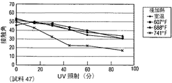
被覆した基体を、その被覆表面の所で24W/m2の強度になるようにしたUVA−340光源からUV輻射線に露出し、被覆上の水滴の接触角を時間と共に測定した。この手順の結果を試料46〜53について、夫々図4〜11に示す。図中、凡例の数字は、上で述べたように後加熱の温度(°F)を示している。
【0111】
図4〜11から、予熱をしない(図8)酸化ジルコニウム(73Å)/酸化チタン(164Å)被覆(試料50)の場合、本発明の被覆は、チタニア(173Å)被覆(試料46)単独の場合と比較して、243℃(470°F)より高い後加熱で、水の接触角を著しく減少したことが分かる(図4)。188℃(370°F)に予熱した本発明の同様な被覆(試料52)の場合、同様に予熱したチタニア被覆単独(試料48)と比較して、接触角は後加熱がなくても一層小さくなる(図10と6を比較されたい)。
【0112】
図9に示したように、予熱をしない酸化ジルコニウム(155Å)/チタニア(287Å)被覆(試料51)の場合、その被覆は、二酸化チタン(397Å)被覆単独(試料47)の場合よりも一層低い接触角を示し(図5)、その接触角は後加熱で減少し続けた。188℃(370°F)に予熱した同様な被覆(試料53)の場合、本発明の被覆は、後加熱がなくても良好な親水性を示した。親水性又は超親水性(即ち、5°に等しいか又はそれより小さい接触角)を達成するのに後加熱を必要としないことにより、本発明の方法を実施することにより著しい時間及びエネルギーの節約を達成することができる。
【0113】
図12及び13は、試料52の被覆の複製被覆についての予熱及び後加熱温度の影響を例示している。図12は、121℃(250°F)、149℃(300°F)、及び188℃(370°F)へ予熱した基体の場合の、後加熱温度に対するUV(被覆表面で24W/m2の強度を有する340nm)を60分間照射した場合の接触角のグラフである。図12から、予熱温度が上昇するにつれて、接触角が減少することが分かる。予熱は、約260℃(500°F)までの後加熱温度に後加熱することよりも、得られる接触角に対し一層大きな影響を与えることが分かる。図13は、127℃(261°F)、198℃(388°F)、及び257℃(495°F)の後加熱温度について、基体を予熱することは、後加熱よりも接触角に一層大きな影響を与えると思われることを示している。
【0114】
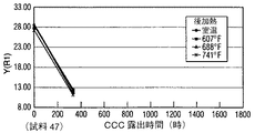
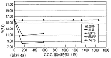
特徴3(化学的耐久性)
試料46〜53の複製被覆を、慣用的クリーブランド・コンデンゼイション・テスト(Cleveland Condensation Test)(CCC)装置〔オハイオ州クリーブランドのQ−パネル社から市販されているコンデンゼイション・テスター(Condensation Tester)Q.C.T.〕に従って試験した。被覆劣化度を、市販のBYK−ガードナー(Gardner)TCSメーターを用いて被覆の反射度〔三刺激値及び図中に示されたY又はY(R1)によって表される〕を測定することにより決定した。結果を図14〜21に示す。図14及び15に示されているように、試料46及び47(チタニア単独、予熱なし)は、良くないCCC結果を示していた。ここで用いる「良くない」とは、被覆の劣化を示す観察反射率の低下によって証明されるように、被覆が400時間より長いCCC試験に耐えられなかったことを意味する。図16及び17の試料48及び49(チタニア単独、予熱使用)は、幾らかよい結果を示していた。しかし、図18及び19の試料50及び51(ジルコニア/チタニア、予熱なし)は、予熱のないチタニア被覆よりも良いCCC結果を示していた。図20及び21の試料52及び53(ジルコニア/チタニア、予熱使用)は、予熱を用いたチタニア被覆よりも著しく改良されたCCC結果を示していたことは全く思いがけないことであった。例えば、試料53(図21)は、後加熱をしなくても、UV輻射線(340nmで、24W/m2の強度)に40分間露出した後、10°より小さい光活性親水性を有する被覆を与えるのみならず、全く以外にも良好なCCC結果を与えた。
【0115】
図22〜25は、試料52の複製被覆について、127℃(261°F)、198℃(388°F)、257℃(495°F)、294℃(561°F)の後加熱温度、及び室温、121℃(250°F)(図22)、149℃(300°F)(図23)、及び188℃(370°F)(図24)の予熱温度の場合のCCC試験結果を示している。これらの結果から、予熱温度が高くなるにつれて、後加熱の被覆の化学的耐久性に与える影響は次第に少なくなると思われる。図25は、この被覆について、もし基体を約188℃(370°F)に加熱すると、約294℃(561°F)より低い後加熱は被覆の化学的耐久性に対する影響が殆ど又は全くないように見えることを示している。
【0116】
特徴4(光触媒性)
本発明の被覆の幾つかを、標準ステアリン酸試験に従って光触媒活性度について測定した。表VIは、これらの測定で0.93より大きな統計R2値を有する結果を示している。光触媒活性度値は、cm-1/分の単位で示されている。
【0117】
表VIから分かるように、試験した被覆は評価した条件下で光触媒活性度を示している。光触媒活性度について試験した他の試料の場合、結果は0.93より小さいR2値を示し、それらの結果は統計的に価値のないものになり、従って、これらの値は列挙してない。
【0119】
本発明に、上の記載で開示した概念から離れることなく、修正を行えることは、当業者によって容易に認められるであろう。従って、ここに詳細に記述した特別な態様は単に例示的なものであり、本発明の範囲に対する限定ではなく、本発明は、特許請求の範囲及びそれと同等な全てのものに亙る全範囲が与えられるべきである。
【図面の簡単な説明】
【図1】 図1は、本発明の特徴を組込んだ被覆積層体を有する基体の部分的側断面図である(実物大ではない)。
【図2】 図2は、本発明の被覆積層体を有する絶縁ガラスユニットの側断面図である(実物大ではない)。
【図3】 図3は、立方晶系酸化ジルコニウム相、ルチル酸化チタン相、及びアナターゼ酸化チタン相についてのフイルム厚さ対ピーク高さカウントの曲線を示すグラフである。
【図4】 図4は、二酸化チタン被覆についての、紫外線に露出した時間(分)に対する水滴の接触角を示すグラフである。
【図5】 図5は、二酸化チタン被覆についての、紫外線に露出した時間(分)に対する水滴の接触角を示すグラフである。
【図6】 図6は、二酸化チタン被覆についての、紫外線に露出した時間(分)に対する水滴の接触角を示すグラフである。
【図7】 図7は、二酸化チタン被覆についての、紫外線に露出した時間(分)に対する水滴の接触角を示すグラフである。
【図8】 図8は、本発明の特徴を組込んた種々の被覆についての、紫外線に露出した時間(分)に対する水滴の接触角を示すグラフである。
【図9】 図9は、本発明の特徴を組込んた種々の被覆についての、紫外線に露出した時間(分)に対する水滴の接触角を示すグラフである。
【図10】 図10は、本発明の特徴を組込んた種々の被覆についての、紫外線に露出した時間(分)に対する水滴の接触角を示すグラフである。
【図11】 図11は、本発明の特徴を組込んた種々の被覆についての、紫外線に露出した時間(分)に対する水滴の接触角を示すグラフである。
【図12】 図12は、図10の被覆と同様な被覆について、接触角対後加熱温度を示すグラフである。
【図13】 図13は、図10の被覆と同様な被覆について、接触角対予熱温度を示すグラフである。
【図14】 図14は、図4の被覆と同様な被覆についてのクリーブランド・コンデンゼイション・テストの結果を示すグラフである。
【図15】 図15は、図5の被覆と同様な被覆についてのクリーブランド・コンデンゼイション・テストの結果を示すグラフである。
【図16】 図16は、図6の被覆と同様な被覆についてのクリーブランド・コンデンゼイション・テストの結果を示すグラフである。
【図17】 図17は、図7の被覆と同様な被覆についてのクリーブランド・コンデンゼイション・テストの結果を示すグラフである。
【図18】 図18は、図8の被覆と同様な被覆についてのクリーブランド・コンデンゼイション・テストの結果を示すグラフである。
【図19】 図19は、図9の被覆と同様な被覆についてのクリーブランド・コンデンゼイション・テストの結果を示すグラフである。
【図20】 図20は、図10の被覆と同様な被覆についてのクリーブランド・コンデンゼイション・テストの結果を示すグラフである。
【図21】 図21は、図11の被覆と同様な被覆についてのクリーブランド・コンデンゼイション・テストの結果を示すグラフである。
【図22】 図22は、121℃(250°F)の予熱温度で、図10の被覆と同様な被覆についての、反射率対クリーブランド・コンデンゼイション・テスト(CCC)露出時間を示すグラフである。
【図23】 図23は、149℃(300°F)の予熱温度で、図10の被覆と同様な被覆についての、反射率対クリーブランド・コンデンゼイション・テスト(CCC)露出時間を示すグラフである。
【図24】 図24は、188℃(370°F)の予熱温度で、図10の被覆と同様な被覆についての、反射率対クリーブランド・コンデンゼイション・テスト(CCC)露出時間を示すグラフである。
【図25】 図25は、図10に示した被覆と同様な被覆についてのCCC反射率結果対予熱温度を示すグラフである。[0001]
Reference related applications
This application is a US Provisional Patent Application Serial No. Serial No. Ser. Claims the right of 60 / 229,449.
[0002]
(Technical field)
The present invention relates to a photoactive coating, a method for changing or obtaining the phase of a material phase, for example, a method for obtaining an amorphous phase of titanium oxide or an anatase crystal phase of titanium oxide from titanium metal, and more particularly, hydrophilicity by photoactivation. And / or a method of obtaining a photocatalytic coating and / or an article made thereby.
[0003]
(Background technology)
For many materials, for example, glass substrates such as architectural windows, automotive transparencys, and aircraft windows, the surface of the substrate is substantially as long as possible for surface contaminants such as general organic and inorganic surface contaminants. It is desirable not to have it. Traditionally, this has often meant cleaning these surfaces. This cleaning operation is typically performed by manually wiping the surface with or without the aid of a chemical cleaning solution. This method is labor intensive, time consuming and / or expensive. Accordingly, there is a need for a glass substrate cleaning method that reduces the frequency and / or necessity of such manual cleaning operations.
[0004]
Certain semiconductor metal oxides are known to provide photoactive (hereinafter referred to as “PA”) coatings. The terms “photoactive” or “photoactively” refer to photogeneration of a hole-electron pair when irradiated with an electromagnetic wave of a specific frequency, typically ultraviolet (UV). These PA coatings typically become photocatalytic (hereinafter referred to as “PC”) above a certain minimum thickness. “Photocatalytic” means a coating that interacts with organic contaminants on the coating surface when exposed to certain electromagnetic waves, such as UV, and degrades or decomposes the organic contaminants. These PC coatings are also self-cleaning if they have sufficient PC activity. “Self-cleaning” means having sufficient PC activity to degrade organic pollutants as quickly as it does not need to be wiped by hand to remove the pollutants. In addition, the PC coating is typically also hydrophilic. “Hydrophilic” means that it is generally wetted with water with a contact angle with water of less than 20 °. The hydrophilicity of the PC coating helps to reduce haze, i.e., the accumulation of water droplets on the coating that reduces visible light transmission through the coated substrate and visibility.
[0005]
Titanium dioxide (TiO2The coating is known to be hydrophilic and / or self-cleaning. However, not all titanium dioxide phases are acceptable as providing a self-cleaning and / or hydrophilic coating. Currently, it is preferred to use the anatase crystalline phase rather than the amorphous or rutile crystalline phase of titanium dioxide to form the PC coating.
[0006]
For example, sputter coating of titanium dioxide has been used as a protective surface coating and is described in US Pat. No. 4,716,086. The limitation of conventional sputter deposition of titanium dioxide is that no anatase crystalline phase is obtained. Another limitation is that it is more efficient to sputter deposit metal films than to deposit metal oxide films. If a metal oxide film is desired, it is an effective method to sputter deposit a metal film on the substrate and then heat the deposited metal film in air. In the case of titanium metal film sputter-deposited, the oxide film formed after heating is not usually anatase phase but rather rutile phase titanium dioxide. Publications relating to the formation of titanium dioxide coatings on glass substrates include US Pat. Nos. 5,595,813 and 6,027,766, and J. Mater. Res. By Paz et al. , Vol. 10, No. 11, pp. 2842-48, November (1995), “Photooxidative Self-cleaning Transparent Titanium Dioxide Films on Glass”.
[0007]
For example, a process for producing sputter-deposited hydrophilic and / or photocatalytic coatings by heating sputter-deposited titanium metal films and converting them to titanium dioxide films that are at least partially in the anatase phase. It will be appreciated that it may be advantageous to provide
[0008]
(Disclosure of the Invention)
The present invention relates to a method for changing or obtaining the phase of a material, including the deposition of a film that facilitates a phase change or favorable deposition. In one embodiment of the present invention, a titanium oxide film is deposited on a cubic or orthorhombic phase zirconium oxide film. In one embodiment of the present invention, the deposited titanium oxide film is in the anatase phase. In another embodiment, a titanium metal film is deposited on a cubic or orthorhombic phase zirconium oxide film and the titanium metal film is heated in the presence of oxygen to form at least a titanium oxide, such as a titanium dioxide film. Partially provided as anatase phase.
[0009]
As another aspect of the present invention, there is provided a method for producing photoactive, eg photoactively hydrophilic and / or photocatalytic coatings. One method for producing a photoactive coating comprises depositing a first coating layer comprising zirconium oxide over at least a portion of a substrate and covering at least a portion of the first coating layer with a photoactive material such as titanium dioxide. Depositing a second coating layer comprising: providing a coated substrate. In one embodiment, the method includes heating the at least one substrate and / or the first coating layer and / or the second coating layer to produce a photoactive article.
[0010]
The present invention relates to articles, for example, windows for residential and commercial use, windows for land, air, sea, outer space and underwater vehicles manufactured using the coated substrate of the present invention. In one embodiment, the article has a substrate, a zirconium oxide layer having a thickness of 10 to 200 mm deposited over at least a portion of the substrate, and a titanium oxide layer deposited over the zirconium oxide layer. In another aspect, the article has a first layer comprising a first material in a cubic or orthorhombic crystalline phase deposited over at least a portion of the substrate. A second layer having at least one photoactive material is deposited over the first layer, for example thereon.
[0011]
(Detailed description of the invention)
"Inner", "outer", "above", "below", "top", "bottom" used here ”, Etc., relates to the present invention as shown in the drawings. However, it will be understood that the invention may take a variety of other orientations and therefore such terms should not be considered limiting. In addition, all numbers representing sizes, physical characteristics, processing parameters, component amounts, reaction conditions, etc. used in the specification and claims are, in each case, modified by the term “about”. It should be understood as possible. Accordingly, unless stated to the contrary, the numerical values set forth in the following specification and claims are approximate and depend on the desired properties sought to be obtained by the present invention. It can be changed. At a minimum, any number should be considered to have been given by referring to at least a number of reported significant numbers and applying the usual rounding method, which is equivalent to the scope of the claims. It is not intended to limit the application of. Further, it should be understood that many of the ranges described herein are inclusive of any small ranges contained therein, including initial and final values. For example, a range stated as “1-10” should be considered to encompass any small range that falls between the lowest value of 1 and the highest value of 10 (including those values). . That is, a small range starting with a minimum value of 1 or more and ending with a maximum value of 10 or less, for example, all ranges such as 5.5-10 are included. Furthermore, as used herein, the term “deposited over” or “provided over” means deposited or applied above but not necessarily in contact with the surface. It also means that For example, a coating “deposited over” a substrate does not exclude the presence of one or more other coating films of the same or different composition located between the deposited coating and the substrate. . Further, all percentages stated herein are by “weight” unless otherwise indicated. The photocatalytic activity values discussed herein were all determined by the conventional stearic acid test described in US Pat. No. 6,027,766, which is hereby incorporated by reference.
[0012]
With reference to FIG. 1, there is shown an
[0013]
[0014]
The
[0015]
The
[0016]
The
[0017]
As an example of the
[0018]
The first and
[0019]
The
[0020]
The
[0021]
Examples of suitable functional coatings used in the present invention are from PPG Industries, Inc. of Pittsburgh, PA, SUNGATE® and SOLARBAN®. It is commercially available as a coating for the system. Such functional coatings typically include one or more anti-reflective coating films that include dielectric or anti-reflective materials such as metal oxides or metal alloy oxides, It is preferably transparent or substantially transparent to visible light. The functional coating (s) may comprise a reflective metal, for example an infrared reflective film made of a noble metal such as gold, copper or silver, or combinations or alloys thereof, and further in the art. As is known, an underlying film or barrier film, such as titanium, covering and / or underlying the metal reflective layer may be provided.
[0022]
An example of an article of manufacture of the present invention is shown in FIG. 2 in the form of an insulating glass (IG)
[0023]
One or both of the
[0024]
U.S. Pat.Nos. 4,379,040, 4,861,669, 4,900,633, 4,920,006, 4,938,857, 5,328,768, And 5,492,750 (herein incorporated by reference) describe MSVD apparatus and methods for sputter coating metal oxide films on substrates, including glass substrates. The MSVD method can be used to deposit one or more of the
[0025]
In one embodiment, the
[0026]
Next, an example of a method for providing the
[0027]
A titanium oxide (eg, titanium dioxide)
[0028]
The
[0029]
In the embodiment described immediately above, the coating
[0030]
The
[0031]
The present invention provides several features that make it advantageous for use in various industrial fields. Four of these features (crystalline phase selection, hydrophilicity, chemical durability, and photocatalytic activity) are discussed next.
[0032]
Feature 1 (Crystal phase selection)
In one aspect, the present invention relates to a technique or method for changing or changing the phase of a film. The term “phase” is used to describe the crystalline or non-crystalline nature of the film. For example, the term “amorphous phase” means that the film is completely or substantially amorphous, ie, the number of diffraction peaks for the amorphous phase as measured by conventional X-ray diffraction (XRD). Means that it does not show a detectable intensity. The term “rutile phase” means that the film or coating has a completely or substantially rutile crystal structure (ie an intensity detectable by measuring the number of diffraction peaks for the rutile phase as measured by XRD). The term “anatase phase” means that the film or coating has a completely or substantially anatase crystal structure (ie, the number of diffraction peaks for the anatase phase as measured by XRD). It shows the intensity that can be detected by measuring with. Yet another feature of the present invention is to change the phase of the titanium oxide film, for example, to change the phase (s) of the sputter deposited film from the amorphous phase to the anatase and / or rutile phase (s). Concerning changing to containing film. This feature of the invention will be appreciated from the following discussion.
[0033]
In the following discussion, the following conditions apply unless indicated to the contrary. The substrates were about 2.3 mm (0.088 inch) thick 30 cm (12 inch) square or 15 cm × 30 cm (6 inch × 12 inch) glass pieces produced by the float process. The air side of the glass pieces was coated. The air side of the glass produced by the float process is the side opposite to the side floating on the molten metal bath as the glass strip moves through the forming chamber. See U.S. Patent Nos. 6,027,766 and 4,091,156 for a discussion of forming a float glass strip. Those glass pieces were cut from a glass sheet cut from a glass strip. The composition, type, shape, and size of the substrate do not limit the invention, and some types of materials that can be used with any type of substrate include, for example, colored glass, plastic, metal, It will be appreciated that ceramic and wood can also be used. Each piece of glass was sputter coated with an
[0034]
Table I below shows power in KW and shows the number of sample passes made at a linear velocity of 304.8 cm (120 inches) per minute. The sputter coated substrate was cut into 10.2 cm (4 inch) square pieces and heated in a furnace. The pieces were moved into a furnace set at a temperature of about 704.4 ° C. (1300 ° F.) and heated for a period of about 2-1 / 2 minutes. The furnace temperature was calculated using uncoated glass pieces of the same size as the coated pieces. The temperature was measured using a thermocouple in contact with the calculated piece surface. The measured temperature was about 657.8 ° C. (1216 ° F.) after about 2-1 / 2 minutes. After heating, the glass pieces were removed, placed in a furnace heated to about 135 ° C. (275 ° F.) for about 4 minutes, and removed. Glass pieces were placed in an oven and the glass pieces were annealed to prevent their breakage and easy to cut. The crystal phase of the sputter-deposited film of titanium metal, titanium oxide, titanium nitride, titanium oxynitride, zirconium metal, and zirconium oxide was measured using X-ray diffraction (XRD). The sample measured was about 2.54 cm (1 inch) square cut from a 102 cm (4 inch) square piece. X-ray diffraction analysis is for diffraction data commercially available from the JCPDS International Center using the Philips X-Pert MPD and the grazing angle method. This was done by comparing the peaks to a standard X-ray diffraction identification card (PDF card). In the obtained image or curve, the “x” axis has 2θ (°), and the “y” axis has intensity based on the count. In the case of zirconium oxide having a cubic phase, the (111) plane has a peak at 2θ of about 30.484 ° (PDF # 27-0997). Orthorhombic zirconium oxide has a peak at 30.537 2θ (PDF # 34-1084), but the peak observed in the present invention is cubic rather than orthorhombic zirconium oxide. Conceivable. However, orthorhombic zirconium oxide would also have been present. Alternatively, in another aspect, the zirconium oxide can have a badeleyite structure (PDF # 37-1484). For the rutile phase titanium oxide, the (110) plane has a peak at 2θ of about 27.446 °, and for the anatase phase titanium oxide, the (101) plane has a 2θ of about 25.281 °. Have a peak in place. Amorphous titanium oxide and amorphous zirconium oxide show no peak when analyzed using X-ray diffraction. Intensity counts for the peaks were determined using software that is part of the Philip apparatus or by estimating the height of the peaks. The peak count indicates the presence of a phase, the higher the count, the more pronounced the phase present. The count is performed every 10 seconds, that is, it corresponds to a 10-second count. The numerical values given here are relative to each other unless otherwise indicated since the instrument was not calculated using the standard prior to making the measurement. When estimating the peak, the count range was determined at the operator's discretion. Specifically, the operator selects one point on the curve or image as the starting point, selects another point on the curve as the end point of the peak, and interpolates the height from the portion of the curve between the starting point and the end point . Including operator judgment, the goal is to identify the presence and relative amounts of anatase crystal phase. For purposes of understanding the present invention, X-ray diffractometry is acceptable to determine the presence of different phases of zirconium oxide and titanium oxide. Recognizing that the use of this method to determine the presence, type, and strength of a phase present does not indicate that the oxide is amorphous, even if no peak is present. There must be. In order to determine whether crystals are present, a more sensitive technique, such as electron diffraction, is required.
[0035]
The area under the curve between the starting and ending points gives the crystal size in the calibrated apparatus. In the case of the present invention, the area under the curve gives the relative magnitude. An important aspect of this study is determining the presence of the anatase phase, so peak height is of primary concern. Table I lists the peak heights by count for samples whose X-ray diffraction images were analyzed using the software. The peak heights for the other samples were not determined using the software, but were estimated from the X-ray diffraction curves. The evaluation for these samples is given in the examination of those samples and is shown in Table I to be approximate by the check mark “ν”.
[0036]
Table I includes target material; atmosphere in the room during coating (gas); power (KW); number of passes; thickness after coating of sputter deposited film; thickness after heating of sputter deposited metal film; For each phase identified to be present, the peak height in 10-second counts is listed; if the peak height is determined by the operator, the value is In Table I, a check mark is shown as “ν”. Values determined using software are given numerically in Table I. The reported thickness of sputter deposited films (except samples 19 and 25) and / or coatings was measured by conventional fluorescent X-ray and stylus profilometer measurements. The reported thicknesses for
[0037]
When peaks are not observed for zirconium oxide and titanium oxide film, a check mark “ν” is placed in the amorphous column. When the presence of a peak is mentioned, it is the presence of a peak at a 2θ angle. Furthermore, the samples were not run in the order described. The samples are practically arranged so that similar coatings can be compared.
[0038]
A zirconium oxide film having a thickness of about 68 mm was deposited on the glass substrate. The X-ray diffraction image of the zirconium oxide film after heating showed a cubic phase. The peak height by count was estimated to be in the range of about 250-350 counts.
[0039]
A zirconium oxide film having a thickness of about 187 mm was deposited on the glass substrate. The X-ray diffraction image of zirconium oxide after heating showed a cubic phase. The peak height by count was estimated to be in the range of about 1000-1100 counts.
[0040]
A zirconium metal film having a thickness of 177 mm was deposited on the glass substrate. The coated glass substrate was heated. The zirconium oxide film formed during heating had a thickness of about 256 mm. The X-ray diffraction image of the zirconium oxide film showed a cubic phase. The peak height by count was estimated to be in the range of about 250-350 counts. Yet another peak was observed at 2θ ° of about 28.5. The peak or its cause has not been clarified. However, the peak did not exist in the X-ray diffraction curve of
[0041]
[0042]
Sample 4
A titanium oxide film having a thickness of 218 mm was deposited on the glass substrate. After heating, the film was analyzed by X-ray diffraction. No peak was observed.
[0043]
A titanium film having a thickness of 109 mm was deposited on a glass substrate and the coated substrate was heated. The film thickness after heating was 207 mm. The titanium oxide film was analyzed by X-ray diffraction. No peak was observed.
[0044]
Sample 6
A zirconium oxide film having a thickness of 20 mm was deposited on the glass substrate, and a titanium oxide film having a thickness of 220 mm was deposited on the zirconium oxide film. The X-ray diffraction image showed no peak for zirconium oxide film or titanium oxide film. The absence of a peak indicated that the zirconium oxide film and the titanium oxide film were amorphous.
[0045]
Sample 7
Sample 7 was obtained by repeating sample 6. It was confirmed that neither the zirconium oxide film nor the titanium oxide film had a peak.
[0046]
A zirconium oxide film having a thickness of 31 mm was deposited on the glass substrate, and a titanium oxide film having a thickness of 221 mm was deposited on the zirconium oxide film. After heating, the coated substrate was analyzed by X-ray diffraction. The zirconium oxide film did not have a peak indicating the presence of cubic zirconium. The titanium oxide had a rutile phase with a peak height of about 94 counts. Anatase was not observed.
[0047]
A zirconium oxide film having a thickness of 45 mm was deposited on the glass substrate, and a titanium oxide film having a thickness of 215 mm was deposited on the zirconium oxide film. After heating, the coated substrate was analyzed by X-ray diffraction. No cubic zirconium oxide peak was observed. The titanium oxide had a 171 count high rutile peak and a 310 count high anatase peak.
[0048]
A zirconium oxide film having a thickness of 45 mm was deposited on the glass substrate, and a titanium oxide film having a thickness of 215 mm was deposited on the zirconium oxide film. The X-ray diffraction image of the heated substrate did not have a cubic zirconium oxide peak. The image showed a titanium dioxide rutile peak with a peak at 235 counts and an anatase peak at 475 counts high.
[0049]
Sample 11
A zirconium oxide film having a thickness of 65 mm was deposited on the glass substrate, and a titanium oxide film having a thickness of 215 mm was deposited on the zirconium oxide film. The X-ray diffraction image has a measurement peak as high as 283 counts for cubic zirconium oxide, a measurement peak as high as 158 counts for the rutile phase of titanium oxide, and a measurement peak as high as 665 counts for the anatase phase. Had a peak.
[0050]
Sample 12
A zirconium oxide film having a thickness of 91 mm was deposited on the glass substrate, and a titanium oxide film having a thickness of 217 mm was deposited on the zirconium oxide film. The X-ray diffraction image has a measurement peak as high as 416 counts for cubic zirconium oxide, a measurement peak as high as 210 counts for the rutile phase of titanium oxide, and a high peak of 258 counts for the anatase phase of titanium oxide. Had a measured peak.
[0051]
Sample 13
A zirconium oxide film having a thickness of 105 mm was deposited on the glass substrate, and a titanium oxide film having a thickness of 221 mm was deposited on the titanium oxide film. The X-ray diffraction image has a measurement peak as high as 548 counts for cubic zirconium oxide, a measurement peak as high as 171 counts for the rutile phase of titanium oxide, and a high count of 62 counts for the anatase phase of titanium oxide. Had a measured peak.
[0052]
Sample 14
A zirconium oxide film having a thickness of 153 mm was deposited on the glass substrate, and a titanium oxide film having a thickness of 221 mm was deposited on the zirconium oxide film. The X-ray diffraction image had a measurement peak with a height of 555 counts for cubic zirconium oxide and a measurement peak with a height of 85 counts for rutile titanium oxide. No measurable anatase titanium oxide peak was observed.
[0053]
A zirconium oxide film having a thickness of 190 mm was deposited on the glass substrate, and a titanium oxide film having a thickness of 215 mm was deposited on the zirconium oxide film. The X-ray diffraction image had a measurement peak with a height of 690 counts for cubic zirconium oxide and a measurement peak with a height of 19 counts for rutile titanium oxide. No measurable anatase titanium oxide peak was observed.
[0054]
Sample 16
Sample 16 was a repeat of
[0055]
Sample 17
A zirconium oxide film having a thickness of 184 mm was deposited on the glass substrate, and a titanium metal film having a thickness of 106 mm was deposited on the zirconium oxide film. After heating, the titanium oxide film had a thickness of 205 mm. From the X-ray diffraction image, cubic zirconium oxide was expected to have a peak height of 1000 to 1100 counts. No peaks were observed for rutile and anatase.
[0056]
Sample 18
A zirconium metal film having a thickness of 64 mm was deposited on the glass substrate. A titanium oxide film was deposited on the zirconium metal film and had a thickness of 220 mm. After heating, the zirconium oxide had a thickness of 93 mm. The X-ray diffraction image had a measurement peak as high as 208 counts for cubic zirconium oxide and a measurement peak as high as 146 counts for the rutile phase of titanium oxide. No measurable anatase titanium oxide peak was observed.
[0057]
Sample 19
A zirconium metal film having a thickness of 148 mm was deposited on the glass substrate. A titanium oxide film having a thickness of 215 mm was deposited on the zirconium metal film. After heating, the zirconium oxide film had a thickness of 264 mm. Neither cubic zirconium oxide nor rutile or anatase titanium oxide peaks were observed in the X-ray diffraction curve.
[0058]
A zirconium metal film having a thickness of 87 mm was deposited on the glass substrate. A titanium oxide film having a thickness of 225 mm was deposited on the zirconium metal film. After heating, the zirconium oxide film had a thickness of 126 mm. The X-ray diffraction image has a measured height of 259 counts for cubic zirconium oxide, a measured peak of 146 counts for rutile titanium oxide, and a measured peak of 80 counts for anatase oxide. It was.
[0059]
Sample 21
A zirconium metal film having a thickness of 182 mm was deposited on the glass substrate, and a titanium metal film having a thickness of 113 mm was deposited on the zirconium metal film. After heating, the zirconium oxide film had a thickness of 263 mm and the titanium oxide film had a thickness of 214 mm. X-ray diffraction images showed no measurable peak for cubic zirconium oxide and anatase titanium oxide. From the X-ray diffraction image, rutile titanium oxide was expected to have a peak height of 900-1000 counts.
[0060]
A zirconium metal film having a thickness of 87 mm was deposited on a glass substrate, and a titanium metal film having a thickness of 115 mm was deposited on the zirconium metal film. After heating, the zirconium oxide film had a thickness of 126 mm and the titanium oxide film had a thickness of 217 mm. X-ray diffraction images did not show measurable peaks for cubic zirconium oxide and rutile and anatase titanium oxide.
[0061]
Sample 23
A titanium oxide film having a thickness of 218 mm was deposited on the glass substrate, and a titanium metal film having a thickness of 110 mm was deposited on the titanium oxide film. After heating, the titanium metal film had a thickness of 208 mm. X-ray diffraction images did not show measurable peaks for rutile and anatase titanium oxide.
[0062]
A titanium metal film having a thickness of 58 mm was deposited on the glass substrate. After heating, the film was a titanium oxide film having a thickness of 110 mm. A titanium oxide film having a thickness of 223 mm was deposited on the titanium metal film. X-ray diffraction images did not show measurable peaks for rutile and anatase titanium oxide.
[0063]
A titanium metal film having a thickness of 119 mm was deposited on the glass substrate. After heating, the film was a titanium oxide film having a thickness of 249 mm. A titanium oxide film having a thickness of 215 mm was deposited on the titanium metal film. X-ray diffraction images did not show measurable peaks for rutile and anatase titanium oxide.
[0064]
A titanium nitride film having a thickness of 216 mm was deposited on the glass substrate. The film thickness after heating was 384 mm. The composition of the film was not analyzed. The film during heating is expected to have been oxidized, but to what extent it was not determined. Thus, the film may contain titanium nitride, titanium oxynitride, or titanium oxide. A titanium film having a thickness of 119 mm was deposited on the titanium nitride film. After heating, the titanium oxide film had a thickness of 223 mm. The X-ray diffraction image showed a rutile peak. It was not known whether the peak was from a heated titanium rutile film or a heated titanium metal film, or a combination thereof. Rutile was expected to have a peak height of 100-250 counts. Anatase peak was not observed.
[0065]
Sample 27
A zirconium oxide film having a thickness of 190 mm was deposited on a glass substrate. An unknown thickness of titanium nitride film was deposited on the zirconium oxide film. The titanium nitride film after heating had a thickness of 364 mm. See the discussion in
[0066]
A 10.2 cm (4 inch) square piece of
[0067]
Sample 29
A 10.2 cm (4 inch) square piece of
[0068]
[0069]
Sample 31
Sample 31 was a repeat of sample 29. However, after depositing a titanium oxide film, the coated glass was subjected to a second heating. The X-ray diffraction image had a cubic zirconium oxide peak as high as 285 counts and a rutile titanium oxide peak as high as 246 counts. Anatase peak was not observed.
[0070]
A zirconium oxide film having a thickness of 173 mm was deposited on the glass substrate. After heating the glass substrate, a titanium metal film having a thickness of 115 mm was deposited on the heated zirconium oxide coated glass substrate. The coated glass substrate was heated and the titanium oxide film had a thickness of 217 mm. The X-ray diffraction image had a cubic zirconium oxide peak with a height of 932 counts. No rutile or anatase titanium oxide peak was observed.
[0071]
Sample 33
A zirconium oxide film having a thickness of 65 mm was deposited on the glass substrate, and titanium metal having a thickness of 115 mm was deposited on the zirconium oxide. The glass substrate was heated. After heating, a titanium oxide film having a thickness of 217 mm was deposited on the heated zirconium oxide coated glass substrate. The X-ray diffraction image had a cubic zirconium oxide peak as high as 288 counts. No rutile or anatase titanium oxide peak was observed.
[0072]
The study of Samples 1-33 shows that when the peak heights for both the anatase titanium oxide phase and the rutile titanium oxide phase of Samples 6-16 are plotted as a function of the thickness of the oxide zirconium layer, a substantially bell-shaped curve (Fig. 3). Table II below shows the peak counts of the cubic zirconium oxide phase and the rutile and anatase titanium oxide phases for Samples 6-16. The first layer for each of Samples 6-16 is zirconium oxide and the second layer for each of Samples 6-16 is titanium oxide. It should be noted that the thicknesses of the titanium oxide layers of Samples 6-16 are the same. This is unexpected, as the bell-shaped curve for peak height is the result of a change in the thickness of the zirconium oxide layer and not the change in the thickness of the titanium oxide layer. This conclusion is supported by the fact that the shape of the peak height increase for the zirconium oxide phase is not bell-shaped.
[0073]
Note further that the value of sample 16 is not plotted in the curve shown in FIG. This is because the peak count for the titanium oxide phase rutile was abnormally larger than the peak height for the rutile titanium oxide phase of
[0079]
In the following samples 34-37, the deposition parameters were controlled to deposit a coating having a zirconium oxide layer thickness of about 65-75 mm, which would give the maximum peak height count to the anatase titanium oxide phase, respectively ( See Table II). The deposition parameters for samples 34-45 are shown in Table III below. In the
[0080]
Sample 34
A zirconium oxide film having a thickness of 71 mm was deposited on the glass substrate, and then a titanium oxide film having a thickness of 130 mm was deposited on the zirconium oxide film. The X-ray diffraction image had a measured peak as high as 241 counts for the cubic zirconium oxide phase and a measured peak as high as 164 counts for the rutile titanium oxide phase. Anatase titanium oxide peak was not observed.
[0081]
A zirconium oxide film having a thickness of 65 mm was deposited on the glass substrate, and then a titanium oxide film having a thickness of 65 mm was deposited on the zirconium oxide film. The X-ray diffraction image had a measured peak as high as 267 counts for the cubic zirconium oxide phase. No rutile or anatase titanium oxide phase peak was observed.
[0082]
(Note: For
[0083]
A zirconium oxide film having a thickness of 65 mm was deposited on the glass substrate, and then a titanium oxide film having a thickness of 177 mm was deposited on the zirconium oxide film. The X-ray diffraction image had a measured peak of 1136 height for the cubic zirconium oxide phase and a measured peak of 1169 height for the rutile titanium oxide phase. A trace amount of the anatase titanium oxide peak was observed.
[0084]
Sample 37
A zirconium oxide film having a thickness of 62 mm was deposited on the glass substrate, and then a titanium oxide film having a thickness of 192 mm was deposited on the zirconium oxide film. The X-ray diffraction image has a measured peak of 1315 height for the cubic zirconium oxide phase, 845 for the rutile titanium oxide phase and 2284 height for the anatase titanium oxide phase. It was.
[0085]
A zirconium oxide film having a thickness of 173 mm was deposited on the glass substrate. A titanium oxide film having a thickness of 114 mm was deposited on the zirconium oxide film. X-ray diffraction images were obtained, but peak heights were not estimated or calculated. From the X-ray diffraction image, the peaks of the cubic zirconium oxide phase and the displaced peaks of the rutile titanium oxide phase were observed. The zirconium oxide phase was much more pronounced than the rutile titanium oxide phase. No peak was observed for the anatase titanium oxide phase.
[0086]
Sample 39
Sample 39 is similar to sample 34. However, before heating the coated substrate with zirconium oxide and titanium oxide film, a titanium metal film having a thickness of 48 mm was further deposited on the titanium oxide film. The coated substrate was heated to oxidize the heated titanium metal film, and the resulting titanium oxide film had a thickness of 90 mm. The X-ray diffraction image showed a cubic zirconium oxide phase having a peak count of 240, a rutile titanium oxide phase having a peak count of 178, and an anatase titanium oxide phase having a peak count of 187 counts.
[0087]
[0088]
Sample 41
Sample 41 is similar to
[0089]
A zirconium oxide film having a thickness of 62 mm was deposited on the glass substrate, a titanium oxide film having a thickness of 98 mm was deposited on the zirconium oxide, and a titanium metal film having a thickness of 46 mm was deposited on the titanium oxide film. Vapor deposited on top. The coated substrate was heated and the titanium oxide thickness by oxidation of the titanium metal was calculated to be 87 mm. X-ray diffraction images were obtained, but peak heights were not estimated or calculated. From the X-ray diffraction image, peaks were observed for the zirconium oxide phase and the rutile titanium oxide phase. For the anatase titanium oxide phase, neither a peak nor a slight amount was observed.
[0090]
Sample 43
Sample 43 is similar to
[0091]
A zirconium oxide film having a thickness of 57 mm is deposited on the glass substrate, a titanium metal having a thickness of 25 mm is deposited on the zirconium oxide film, and a titanium oxide film having a thickness of 65 mm is deposited on the titanium metal. Vapor deposited. The coated glass was heated in air and the calculated thickness of the titanium oxide film due to the oxidation of the titanium metal film was 47 mm. An X-ray diffraction image was obtained, but the peak height was not estimated and was not obtained. From the X-ray diffraction image, a peak was observed for the cubic zirconium oxide phase. No peaks were observed for the rutile and anatase titanium oxide phases.
[0092]
Sample 45
Sample 45 is similar to
[0093]
From the results of samples 34 to 37, it is observed that the anatase titanium oxide phase has developed with a titanium oxide film having a thickness of about 169 mm. It will be appreciated that the thickness at which anatase titanium oxide can develop is reduced.
[0094]
Self-cleaning of anatase and / or rutile titanium oxide for residential and commercial windows, automotive transparency such as side lite, rear window, windshield, roof window, oven door, mirror, etc. This can be done to give a film.
[0095]
Yet another glass substrate was coated with titanium oxide, zirconium oxide, and a coating of the present invention over which zirconium oxide was deposited (samples 54-68 shown in Table IV). The deposition parameters and intensity measurements for these samples 54-68 are shown in Table IV.
[0098]
[0099]
Samples 58 to 62 show the influence of the thickness (70 to 166 mm) of the zirconium oxide layer having the titanium oxide layer having a thickness (382 to 441 mm). A thick zirconium oxide layer does not reduce the magnitude of the anatase peak (101) intensity.
[0100]
Samples 63 and 64 are comparative samples of titanium dioxide. Compared to Samples 58-62, Samples 58-62 of the present invention show significantly higher anatase peak (101) intensity.
[0101]
Samples 65-68 are zirconium oxide coatings showing the peak intensity of the cubic phase (111) zirconium oxide, which is clearly a thin film showing the difference in peak positions of the anatase, rutile, and cubic phases. Show.
[0102]
Table IV also shows the presence of rutile, but the strength is significantly lower.
[0103]
Feature 2 (Hydrophilic)
The coating of the present invention was compared with a conventional titanium dioxide coating under various conditions to determine the effect on the coating hydrophilicity of the present invention.
[0106]
A transparent glass substrate having a thickness of 2.3 nm was coated using a commercially
[0107]
Phase peak counts were also measured as described in
[0108]
In the case of titanium oxide with a zirconium oxide first layer preheated to 188 ° C. (370 ° F.),
[0109]
The coated substrate is 24 W / m at the coated surface.2The contact angle of water droplets on the coating was measured over time by exposure to UV radiation from a UVA-340 light source designed to have an intensity of. The results of this procedure are shown in FIGS. 4 to 11 for
[0111]
From FIGS. 4 to 11, the preheating is not performed (FIG. 8). In the case of zirconium oxide (73Å) / titanium oxide (164Å) coating (sample 50), the coating of the present invention is the case of titania (173 () coating (sample 46) alone. It can be seen that post-heating above 243 ° C. (470 ° F.) significantly reduced the water contact angle (FIG. 4). In the case of a similar coating of the present invention pre-heated to 188 ° C. (370 ° F.) (sample 52), the contact angle is much smaller without post-heating as compared to a similarly pre-heated titania coating alone (sample 48). (Compare FIGS. 10 and 6).
[0112]
As shown in FIG. 9, the zirconium oxide (155Å) / titania (287Å) coating (sample 51) without preheating has a lower coating than the titanium dioxide (397Å) coating alone (sample 47). A contact angle was shown (FIG. 5), which continued to decrease with post-heating. In the case of a similar coating pre-heated to 188 ° C. (370 ° F.) (Sample 53), the coating of the present invention showed good hydrophilicity even without post-heating. By not requiring post-heating to achieve hydrophilicity or superhydrophilicity (ie, contact angle equal to or less than 5 °), significant time and energy savings are achieved by carrying out the method of the present invention. Can be achieved.
[0113]
FIGS. 12 and 13 illustrate the effect of preheating and post heating temperatures on the replicate coating of the
[0114]
Feature 3 (chemical durability)
Duplicate coatings of Samples 46-53 were applied to a conventional Cleveland Condensation Test (CCC) device (Condensation Tester commercially available from Q-Panel, Cleveland, Ohio). Q. C. T.A. ] Was tested according to The degree of coating degradation is determined by measuring the reflectance of the coating (expressed by tristimulus values and Y or Y (R1) shown in the figure) using a commercially available BYK-Gardner TCS meter. did. The results are shown in FIGS. As shown in FIGS. 14 and 15,
[0115]
FIGS. 22-25 illustrate post-heating temperatures of 127 ° C. (261 ° F.), 198 ° C. (388 ° F.), 257 ° C. (495 ° F.), 294 ° C. (561 ° F.) Shown are CCC test results for room temperature, preheating temperatures of 121 ° C. (250 ° F.) (FIG. 22), 149 ° C. (300 ° F.) (FIG. 23), and 188 ° C. (370 ° F.) (FIG. 24). Yes. From these results, it appears that the effect of post-heating on the chemical durability of the coating gradually decreases as the preheating temperature increases. FIG. 25 shows that for this coating, if the substrate is heated to about 188 ° C. (370 ° F.), post-heating below about 294 ° C. (561 ° F.) has little or no effect on the chemical durability of the coating. It shows that it looks like.
[0116]
Feature 4 (photocatalytic)
Some of the coatings of the present invention were measured for photocatalytic activity according to a standard stearic acid test. Table VI shows a statistical R greater than 0.93 for these measurements.2Results with values are shown. The photocatalytic activity value is cm-1It is shown in units of / min.
[0117]
As can be seen from Table VI, the coatings tested exhibited photocatalytic activity under the conditions evaluated. For other samples tested for photocatalytic activity, the result is less than 0.93 R2The values are shown and their results are statistically worthless, so these values are not listed.
[0119]
It will be readily appreciated by those skilled in the art that the present invention can be modified without departing from the concepts disclosed in the above description. Accordingly, the specific embodiments described in detail herein are merely exemplary and are not a limitation on the scope of the invention, but the invention is given the full scope of the claims and all equivalents thereof. Should be done.
[Brief description of the drawings]
FIG. 1 is a partial cross-sectional view (not to scale) of a substrate having a coated laminate incorporating features of the present invention.
FIG. 2 is a side sectional view of an insulating glass unit having a coated laminate of the present invention (not a full size).
FIG. 3 is a graph showing curves of film thickness versus peak height count for cubic zirconium oxide phase, rutile titanium oxide phase, and anatase titanium oxide phase.
FIG. 4 is a graph showing the contact angle of water droplets with respect to the time (minutes) exposed to ultraviolet rays for a titanium dioxide coating.
FIG. 5 is a graph showing the contact angle of a water droplet with respect to the time (minutes) exposed to ultraviolet rays for a titanium dioxide coating.
FIG. 6 is a graph showing the contact angle of water droplets with respect to the time (minutes) exposed to ultraviolet rays for a titanium dioxide coating.
FIG. 7 is a graph showing the contact angle of water droplets with respect to the time (minutes) exposed to ultraviolet rays for a titanium dioxide coating.
FIG. 8 is a graph showing the contact angle of a water drop versus time (minutes) exposed to ultraviolet light for various coatings incorporating features of the present invention.
FIG. 9 is a graph showing the contact angle of a water drop versus time (minutes) exposed to ultraviolet light for various coatings incorporating features of the present invention.
FIG. 10 is a graph showing the contact angle of a water drop against time (minutes) exposed to ultraviolet light for various coatings incorporating features of the present invention.
FIG. 11 is a graph showing the contact angle of a water drop versus time (minutes) exposed to ultraviolet light for various coatings incorporating features of the present invention.
12 is a graph showing contact angle versus post-heating temperature for a coating similar to the coating of FIG.
13 is a graph showing contact angle versus preheating temperature for a coating similar to that of FIG.
FIG. 14 is a graph showing the results of the Cleveland Condensation Test for a coating similar to the coating of FIG.
FIG. 15 is a graph showing the results of the Cleveland Condensation Test for a coating similar to the coating of FIG.
FIG. 16 is a graph showing the results of the Cleveland Condensation Test for a coating similar to the coating of FIG.
FIG. 17 is a graph showing the results of the Cleveland Condensation test for a coating similar to the coating of FIG.
FIG. 18 is a graph showing the results of the Cleveland Condensation Test for a coating similar to the coating of FIG.
FIG. 19 is a graph showing the results of the Cleveland Condensation Test for a coating similar to the coating of FIG.
FIG. 20 is a graph showing the results of the Cleveland Condensation test for a coating similar to the coating of FIG.
FIG. 21 is a graph showing the results of the Cleveland Condensation Test for a coating similar to the coating of FIG.
FIG. 22 is a graph showing reflectivity versus Cleveland Condensation Test (CCC) exposure time for a coating similar to the coating of FIG. 10 at a preheat temperature of 121 ° C. (250 ° F.). is there.
FIG. 23 is a graph showing reflectivity versus Cleveland Condensation Test (CCC) exposure time for a coating similar to that of FIG. 10 at a preheat temperature of 149 ° C. (300 ° F.). is there.
24 is a graph showing reflectivity versus Cleveland Condensation Test (CCC) exposure time for a coating similar to that of FIG. 10 at a preheat temperature of 188 ° C. (370 ° F.). is there.
FIG. 25 is a graph showing CCC reflectivity results versus preheating temperature for a coating similar to the coating shown in FIG.
Claims (39)
第一形成工程として、基体表面の少なくとも一部分を覆って、アナターゼまたはルチルから選択される少なくとも一つの結晶相を有する酸化チタンフイルムの成長を促進する、立方晶系結晶相の酸化ジルコニウムを有するフイルムを15Åに等しいか又はそれより大きい厚みに形成し、そして
第二形成工程として、前記酸化ジルコニウムフイルムの上に酸化チタンフイルムを形成し、そして、
基体、酸化ジルコニムフイルム又は酸化チタンフイルムの少なくとも一つを100℃(212°F)に等しいか又はそれより高い温度に加熱し、酸化チタンフイルムにアナターゼまたはルチルから選択される少なくとも一つの結晶相を与えることを含む方法。A method of forming a titanium oxide film having at least one crystalline phase selected from anatase or rutile ,
As a first forming step, a film having a cubic crystal phase zirconium oxide that covers at least a part of the substrate surface and promotes the growth of a titanium oxide film having at least one crystal phase selected from anatase or rutile is formed. Forming a thickness equal to or greater than 15 mm, and, as a second forming step, forming a titanium oxide film on the zirconium oxide film ; and
At least one of the substrate, zirconium oxide film or titanium oxide film is heated to a temperature equal to or higher than 100 ° C. (212 ° F.), and the titanium oxide film has at least one crystal phase selected from anatase or rutile. A method that includes giving.
第二形成工程として、前記第一被覆層の少なくとも一部分を覆って酸化チタンを含む第二被覆層を形成し、被覆された基体を与える、
工程を含む光活性被覆製造方法。As a first forming step, to form a first coating layer comprising a zirconium oxide cubic binding phase over at least a portion of the substrate, and a second forming step, over at least a portion of the first coating layer Forming a second coating layer comprising titanium oxide to provide a coated substrate;
A method for producing a photoactive coating comprising the steps.
前記基体の少なくとも一部分を覆って形成した10Å〜200Åの厚さを有する立方晶系結晶相を有する酸化ジルコニウム層、及び
前記酸化ジルコニウム層を覆って形成した酸化チタン層、
を有する物品。Substrate,
At least zirconium oxide layer having a cubic binding phase having a thickness of 10Å~200Å formed over a portion, and titanium oxide layer formed over said zirconium oxide layer of the substrate,
Articles with
基体の少なくとも一部分を覆って堆積した第一層で、立方晶系結晶相の酸化ジルコニウムを含む第一層、及び
前記第一層を覆って堆積した第二層で、少なくとも一種類の二酸化チタンを含む第二層、
を有する物品。Substrate,
In the first layer deposited over at least a portion of the substrate, the first layer comprising zirconium oxide cubic binding phase, and a second layer deposited over the first layer, at least one of titanium dioxide Including the second layer,
Articles with
前記第一表面の少なくとも一部分を覆って立方晶系結晶相を有する酸化ジルコニウム層を堆積し、
酸化ジルコニウム層の上に、第一表面の少なくとも一部分を覆って酸化チタン層を含む光活性被覆を第一形成工程として形成し、そして
前記第二表面の少なくとも一部分を覆って機能性被覆を第二形成工程として形成する、
工程を含む被覆方法。In a method of coating a substrate having a first surface and a second surface,
Depositing a zirconium oxide layer having a cubic binding phase over at least a portion of said first surface,
On the zirconium oxide layer, a photoactive coating comprising a titanium oxide layer over at least a portion of the first surface is formed as a first forming step, and a functional coating is coated over at least a portion of the second surface. Forming as a forming process,
A coating method comprising the steps.
Applications Claiming Priority (3)
| Application Number | Priority Date | Filing Date | Title |
|---|---|---|---|
| US22944900P | 2000-08-31 | 2000-08-31 | |
| US09/943,163 US6677063B2 (en) | 2000-08-31 | 2001-08-30 | Methods of obtaining photoactive coatings and/or anatase crystalline phase of titanium oxides and articles made thereby |
| PCT/US2001/027355 WO2002040417A2 (en) | 2000-08-31 | 2001-08-31 | Methods of obtaining photoactive coatings and/or anatase crystalline phase of titanium oxides and articles made thereby |
Publications (3)
| Publication Number | Publication Date |
|---|---|
| JP2004513864A JP2004513864A (en) | 2004-05-13 |
| JP2004513864A5 JP2004513864A5 (en) | 2005-06-02 |
| JP4194838B2 true JP4194838B2 (en) | 2008-12-10 |
Family
ID=26923312
Family Applications (1)
| Application Number | Title | Priority Date | Filing Date |
|---|---|---|---|
| JP2002542751A Expired - Lifetime JP4194838B2 (en) | 2000-08-31 | 2001-08-31 | Method for obtaining photoactive coating and / or anatase crystalline phase of titanium oxide and articles made thereby |
Country Status (12)
| Country | Link |
|---|---|
| US (1) | US6677063B2 (en) |
| EP (1) | EP1315682B1 (en) |
| JP (1) | JP4194838B2 (en) |
| AT (1) | ATE387411T1 (en) |
| AU (2) | AU2002239225B2 (en) |
| CA (1) | CA2417936C (en) |
| DE (1) | DE60133012T2 (en) |
| DK (1) | DK1315682T3 (en) |
| ES (1) | ES2301569T3 (en) |
| MX (1) | MXPA03001686A (en) |
| PT (1) | PT1315682E (en) |
| WO (1) | WO2002040417A2 (en) |
Families Citing this family (79)
| Publication number | Priority date | Publication date | Assignee | Title |
|---|---|---|---|---|
| US7323249B2 (en) * | 2000-08-31 | 2008-01-29 | Ppg Industries Ohio, Inc. | Methods of obtaining photoactive coatings and/or anatase crystalline phase of titanium oxides and articles made thereby |
| US6921579B2 (en) * | 2000-09-11 | 2005-07-26 | Cardinal Cg Company | Temporary protective covers |
| MXPA02009426A (en) * | 2001-02-08 | 2003-10-06 | Cardinal Cg Co | Edge treatments for coated substrates. |
| US6902813B2 (en) * | 2001-09-11 | 2005-06-07 | Cardinal Cg Company | Hydrophilic surfaces carrying temporary protective covers |
| CN1620336A (en) * | 2001-12-21 | 2005-05-25 | 日本板硝子株式会社 | Member having photocatalytic function and method for manufacture thereof |
| JP4116300B2 (en) * | 2002-01-31 | 2008-07-09 | 富士ゼロックス株式会社 | Titanium oxide photocatalytic thin film and method for producing the titanium oxide photocatalytic thin film |
| US8673399B2 (en) * | 2002-05-07 | 2014-03-18 | Nanoptek Corporation | Bandgap-shifted semiconductor surface and method for making same, and apparatus for using same |
| US6733889B2 (en) † | 2002-05-14 | 2004-05-11 | Pilkington North America, Inc. | Reflective, solar control coated glass article |
| JP2004143584A (en) * | 2002-08-29 | 2004-05-20 | Nippon Sheet Glass Co Ltd | Article coated with zirconium compound film, method for producing the article, and sputtering target used for coating with the film |
| EP1398147A1 (en) * | 2002-09-13 | 2004-03-17 | Scheuten Glasgroep | Fire-screening glazing unit |
| US7223523B2 (en) * | 2002-09-18 | 2007-05-29 | Ppg Industries Ohio, Inc. | Demonstration kit and method for enhancing and/or demonstrating photoactive properties |
| FR2845774B1 (en) * | 2002-10-10 | 2005-01-07 | Glaverbel | HYDROPHILIC REFLECTING ARTICLE |
| US20040149307A1 (en) * | 2002-12-18 | 2004-08-05 | Klaus Hartig | Reversible self-cleaning window assemblies and methods of use thereof |
| US20070082205A1 (en) * | 2003-06-09 | 2007-04-12 | Toshiaki Anzaki | Photocatalytic member |
| US20070031681A1 (en) * | 2003-06-20 | 2007-02-08 | Nippon Sheet Glass Co., Ltd. | Member having photocatalytic activity and multilayered glass |
| EP1498176A1 (en) * | 2003-07-16 | 2005-01-19 | Profine GmbH | Photocatalytic coating of a substrate |
| FR2857885B1 (en) * | 2003-07-23 | 2006-12-22 | Saint Gobain | PROCESS FOR THE PREPARATION OF A PHOTOCATALYTIC COATING INTEGRATED IN THE THERMAL TREATMENT OF A GLAZING |
| DE602004010283T2 (en) * | 2003-09-02 | 2008-09-18 | Guardian Industries Corp., Auburn Hills | HEAT-TREATABLE COATED ARTICLE WITH DIAMOND CARBON (DLC) AND / OR ZIRCONIUM IN COATING |
| WO2005035822A1 (en) * | 2003-10-07 | 2005-04-21 | Deposition Sciences, Inc. | Apparatus and process for high rate deposition of rutile titanium dioxide |
| FR2861385B1 (en) * | 2003-10-23 | 2006-02-17 | Saint Gobain | SUBSTRATE, IN PARTICULAR GLASS SUBSTRATE, CARRYING AT LEAST ONE PHOTOCATALYTIC LAYER STACK WITH THE HETEROEPITAXIAL GROWTH LAYER OF THE LAYER |
| US7537801B2 (en) * | 2003-11-04 | 2009-05-26 | Guardian Industries Corp. | Heat treatable coated article with diamond-like carbon (DLC) and/or zirconium in coating |
| EP1693482A4 (en) * | 2003-12-09 | 2008-04-30 | Asahi Glass Co Ltd | Ti OXIDE FILM EXHIBITING PHOTOCATALYTIC ACTIVITY UPON VISIBLE LIGHT IRRADIATION AND PROCESS FOR PRODUCING THE SAME |
| US7294404B2 (en) * | 2003-12-22 | 2007-11-13 | Cardinal Cg Company | Graded photocatalytic coatings |
| WO2005110599A1 (en) * | 2004-05-13 | 2005-11-24 | Nippon Sheet Glass Co., Ltd. | Photocatalytic laminated film |
| JP2008505841A (en) | 2004-07-12 | 2008-02-28 | 日本板硝子株式会社 | Low maintenance coating |
| DE112005001994T5 (en) * | 2004-08-23 | 2007-08-02 | GM Global Technology Operations, Inc., Detroit | Method for improving fuel cell water management |
| JP5301833B2 (en) * | 2004-10-04 | 2013-09-25 | カーディナル・シージー・カンパニー | Thin film coating and temporary protection technology, heat insulating glass unit, and related methods |
| US7923114B2 (en) * | 2004-12-03 | 2011-04-12 | Cardinal Cg Company | Hydrophilic coatings, methods for depositing hydrophilic coatings, and improved deposition technology for thin films |
| US8092660B2 (en) * | 2004-12-03 | 2012-01-10 | Cardinal Cg Company | Methods and equipment for depositing hydrophilic coatings, and deposition technologies for thin films |
| CN101072735B (en) * | 2004-12-06 | 2011-08-10 | 日本板硝子株式会社 | Glass member having photocatalytic function and heat ray reflective function, and double layer glass employing it |
| EP1828071B1 (en) * | 2004-12-16 | 2011-02-09 | AGC Glass Europe | Process for the production of antimicrobial glass type substrate |
| US7498058B2 (en) * | 2004-12-20 | 2009-03-03 | Ppg Industries Ohio, Inc. | Substrates coated with a polycrystalline functional coating |
| US7438948B2 (en) * | 2005-03-21 | 2008-10-21 | Ppg Industries Ohio, Inc. | Method for coating a substrate with an undercoating and a functional coating |
| US20070029186A1 (en) * | 2005-08-02 | 2007-02-08 | Alexey Krasnov | Method of thermally tempering coated article with transparent conductive oxide (TCO) coating using inorganic protective layer during tempering and product made using same |
| US20090117371A1 (en) * | 2006-04-07 | 2009-05-07 | Interpane Entwicklungs-Und Beratungsgesellschaft Mbh & Co. Kg | Weather-resistant layer system |
| WO2007121211A2 (en) * | 2006-04-11 | 2007-10-25 | Cardinal Cg Company | Photocatalytic coatings having improved low-maintenance properties |
| WO2007124291A2 (en) | 2006-04-19 | 2007-11-01 | Cardinal Cg Company | Opposed functional coatings having comparable single surface reflectances |
| US7892662B2 (en) * | 2006-04-27 | 2011-02-22 | Guardian Industries Corp. | Window with anti-bacterial and/or anti-fungal feature and method of making same |
| US7846492B2 (en) * | 2006-04-27 | 2010-12-07 | Guardian Industries Corp. | Photocatalytic window and method of making same |
| US20080011599A1 (en) | 2006-07-12 | 2008-01-17 | Brabender Dennis M | Sputtering apparatus including novel target mounting and/or control |
| FR2911130B1 (en) | 2007-01-05 | 2009-11-27 | Saint Gobain | THIN FILM DEPOSITION METHOD AND PRODUCT OBTAINED |
| US8747630B2 (en) * | 2007-01-16 | 2014-06-10 | Alliance For Sustainable Energy, Llc | Transparent conducting oxides and production thereof |
| WO2008088551A1 (en) * | 2007-01-16 | 2008-07-24 | Midwest Research Institute | Transparent conducting oxides and production thereof |
| JP2008221088A (en) * | 2007-03-09 | 2008-09-25 | Yokohama National Univ | Oxide catalyst and decomposition method of organic component in gas using the same |
| TWI353388B (en) * | 2007-09-12 | 2011-12-01 | Taiwan Textile Res Inst | Method for preparing titanium dioxide |
| JP5474796B2 (en) | 2007-09-14 | 2014-04-16 | 日本板硝子株式会社 | Low maintenance coating and method of manufacturing low maintenance coating |
| DE202008018513U1 (en) | 2008-01-04 | 2014-10-31 | Saint-Gobain Glass France | dispositif |
| GB0803702D0 (en) | 2008-02-28 | 2008-04-09 | Isis Innovation | Transparent conducting oxides |
| US8253012B2 (en) * | 2008-03-17 | 2012-08-28 | Alliance For Sustainable Energy, Llc | High quality transparent conducting oxide thin films |
| FR2929938B1 (en) | 2008-04-11 | 2010-05-07 | Saint Gobain | THIN LAYER DEPOSITION METHOD |
| FR2931147B1 (en) * | 2008-05-19 | 2010-11-19 | Saint Gobain | GLAZING PROVIDED WITH A STACK OF THIN LAYERS |
| US20110076202A1 (en) * | 2008-05-29 | 2011-03-31 | Mitsui Mining & Smelting Co., Ltd | Particulate combustion catalyst, particulate filter and exhaust gas purifying apparatus |
| WO2010044922A1 (en) * | 2008-06-12 | 2010-04-22 | Anguel Nikolov | Thin film and optical interference filter incorporating high-index titanium dioxide and method for making them |
| TW201012973A (en) * | 2008-09-30 | 2010-04-01 | Industrie De Nora Spa | Cathode member and bipolar plate for hypochlorite cells |
| GB0915376D0 (en) | 2009-09-03 | 2009-10-07 | Isis Innovation | Transparent conducting oxides |
| FR2950878B1 (en) | 2009-10-01 | 2011-10-21 | Saint Gobain | THIN LAYER DEPOSITION METHOD |
| US10000411B2 (en) | 2010-01-16 | 2018-06-19 | Cardinal Cg Company | Insulating glass unit transparent conductivity and low emissivity coating technology |
| US9862640B2 (en) | 2010-01-16 | 2018-01-09 | Cardinal Cg Company | Tin oxide overcoat indium tin oxide coatings, coated glazings, and production methods |
| US10000965B2 (en) | 2010-01-16 | 2018-06-19 | Cardinal Cg Company | Insulating glass unit transparent conductive coating technology |
| WO2011088330A2 (en) | 2010-01-16 | 2011-07-21 | Cardinal Cg Company | High quality emission control coatings, emission control glazings, and production methods |
| US11155493B2 (en) | 2010-01-16 | 2021-10-26 | Cardinal Cg Company | Alloy oxide overcoat indium tin oxide coatings, coated glazings, and production methods |
| US10060180B2 (en) | 2010-01-16 | 2018-08-28 | Cardinal Cg Company | Flash-treated indium tin oxide coatings, production methods, and insulating glass unit transparent conductive coating technology |
| FR2963342B1 (en) | 2010-07-27 | 2012-08-03 | Saint Gobain | METHOD FOR OBTAINING A MATERIAL COMPRISING A SUBSTRATE WITH A COATING |
| JP2012142367A (en) * | 2010-12-28 | 2012-07-26 | Hitachi Kokusai Electric Inc | Method for manufacturing semiconductor device and substrate processing apparatus |
| WO2013119550A1 (en) | 2012-02-10 | 2013-08-15 | Alliance For Sustainable Energy, Llc | Thin film photovoltaic devices with a minimally conductive buffer layer |
| MX349068B (en) | 2012-06-21 | 2017-06-28 | Inst Mexicano Del Petróleo | Nanostructured titania semiconductor material and its production process. |
| WO2014077895A1 (en) | 2012-11-19 | 2014-05-22 | Alliance For Sustainable Energy, Llc | Devices and methods featuring the addition of refractory metals to contact interface layers |
| KR20150110500A (en) * | 2012-12-06 | 2015-10-02 | 쌩-고벵 글래스 프랑스 | Fire protection panel and fire protection glazing |
| JP6132536B2 (en) * | 2012-12-11 | 2017-05-24 | キヤノン株式会社 | Optical scanning device, image forming apparatus, and method of manufacturing optical scanning device |
| DE102013016529A1 (en) * | 2013-10-07 | 2015-04-09 | Heraeus Deutschland GmbH & Co. KG | Metal oxide target and process for its preparation |
| US9845663B2 (en) | 2014-04-02 | 2017-12-19 | Halliburton Energy Services, Inc. | Self-cleaning windows for downhole and process chemistry environment |
| FR3021967B1 (en) | 2014-06-06 | 2021-04-23 | Saint Gobain | PROCESS FOR OBTAINING A SUBSTRATE COATED WITH A FUNCTIONAL LAYER |
| DE102015115992A1 (en) * | 2015-09-22 | 2017-03-23 | Technische Universität Darmstadt | Process for the preparation of a coated substrate |
| EP3387163B1 (en) | 2015-12-11 | 2020-04-29 | Cardinal CG Company | Method of coating both sides of a substrate |
| US10526242B2 (en) * | 2016-07-11 | 2020-01-07 | Guardian Glass, LLC | Coated article supporting titanium-based coating, and method of making the same |
| EP3541762B1 (en) | 2016-11-17 | 2022-03-02 | Cardinal CG Company | Static-dissipative coating technology |
| US10611679B2 (en) | 2017-10-26 | 2020-04-07 | Guardian Glass, LLC | Coated article including noble metal and polymeric hydrogenated diamond like carbon composite material having antibacterial and photocatalytic properties, and/or methods of making the same |
| US11028012B2 (en) | 2018-10-31 | 2021-06-08 | Cardinal Cg Company | Low solar heat gain coatings, laminated glass assemblies, and methods of producing same |
| EP3828304A1 (en) | 2019-11-29 | 2021-06-02 | Saint-Gobain Glass France | Thin layer deposition process |
Family Cites Families (52)
| Publication number | Priority date | Publication date | Assignee | Title |
|---|---|---|---|---|
| US4091156A (en) | 1973-03-06 | 1978-05-23 | Ppg Industries, Inc. | Manufactured glass by contiguous float process |
| US4193236A (en) | 1978-01-30 | 1980-03-18 | Ppg Industries, Inc. | Multiple glazed unit having an adhesive cleat |
| US4344986A (en) | 1980-08-08 | 1982-08-17 | Ppg Industries, Inc. | Method of delivering powder coating reactants |
| US4379040A (en) | 1981-01-29 | 1983-04-05 | Ppg Industries, Inc. | Method of and apparatus for control of reactive sputtering deposition |
| JPS5890604A (en) | 1981-11-25 | 1983-05-30 | Toyota Central Res & Dev Lab Inc | Infrared-ray shielding laminate |
| US4393095A (en) | 1982-02-01 | 1983-07-12 | Ppg Industries, Inc. | Chemical vapor deposition of vanadium oxide coatings |
| US4400412A (en) | 1982-02-01 | 1983-08-23 | Ppg Industries, Inc. | Thermochromic vanadium oxide coated glass |
| US4464874A (en) | 1982-11-03 | 1984-08-14 | Hordis Brothers, Inc. | Window unit |
| US4719126A (en) | 1983-02-02 | 1988-01-12 | Ppg Industries, Inc. | Pyrolytic deposition of metal oxide film from aqueous suspension |
| US4971843A (en) | 1983-07-29 | 1990-11-20 | Ppg Industries, Inc. | Non-iridescent infrared-reflecting coated glass |
| US4948677A (en) | 1984-01-31 | 1990-08-14 | Ppg Industries, Inc. | High transmittance, low emissivity article and method of preparation |
| US4610771A (en) | 1984-10-29 | 1986-09-09 | Ppg Industries, Inc. | Sputtered films of metal alloy oxides and method of preparation thereof |
| US4716086A (en) | 1984-12-19 | 1987-12-29 | Ppg Industries, Inc. | Protective overcoat for low emissivity coated article |
| US5028759A (en) | 1988-04-01 | 1991-07-02 | Ppg Industries, Inc. | Low emissivity film for a heated windshield |
| US5059295A (en) | 1986-12-29 | 1991-10-22 | Ppg Industries, Inc. | Method of making low emissivity window |
| US4806220A (en) | 1986-12-29 | 1989-02-21 | Ppg Industries, Inc. | Method of making low emissivity film for high temperature processing |
| US4898790A (en) | 1986-12-29 | 1990-02-06 | Ppg Industries, Inc. | Low emissivity film for high temperature processing |
| US4746347A (en) | 1987-01-02 | 1988-05-24 | Ppg Industries, Inc. | Patterned float glass method |
| JPS63184210A (en) | 1987-01-27 | 1988-07-29 | 日本板硝子株式会社 | Manufacture of transparent conductor |
| US4920006A (en) | 1987-03-26 | 1990-04-24 | Ppg Industries, Inc. | Colored metal alloy/oxynitride coatings |
| US4861669A (en) | 1987-03-26 | 1989-08-29 | Ppg Industries, Inc. | Sputtered titanium oxynitride films |
| US4900633A (en) | 1987-03-26 | 1990-02-13 | Ppg Industries, Inc. | High performance multilayer coatings |
| US4938857A (en) | 1987-03-26 | 1990-07-03 | Ppg Industries, Inc. | Method for making colored metal alloy/oxynitride coatings |
| US4792536A (en) | 1987-06-29 | 1988-12-20 | Ppg Industries, Inc. | Transparent infrared absorbing glass and method of making |
| US4853257A (en) | 1987-09-30 | 1989-08-01 | Ppg Industries, Inc. | Chemical vapor deposition of tin oxide on float glass in the tin bath |
| US4902580A (en) | 1988-04-01 | 1990-02-20 | Ppg Industries, Inc. | Neutral reflecting coated articles with sputtered multilayer films of metal oxides |
| US4834857A (en) | 1988-04-01 | 1989-05-30 | Ppg Industries, Inc. | Neutral sputtered films of metal alloy oxides |
| US4898789A (en) | 1988-04-04 | 1990-02-06 | Ppg Industries, Inc. | Low emissivity film for automotive heat load reduction |
| US5106663A (en) | 1989-03-07 | 1992-04-21 | Tremco Incorporated | Double-paned window system having controlled sealant thickness |
| US5164810A (en) * | 1989-12-06 | 1992-11-17 | General Motors Corporation | Cubic boron nitride bipolar transistor |
| US5328768A (en) | 1990-04-03 | 1994-07-12 | Ppg Industries, Inc. | Durable water repellant glass surface |
| US5142350A (en) * | 1990-07-16 | 1992-08-25 | General Motors Corporation | Transistor having cubic boron nitride layer |
| US5240886A (en) | 1990-07-30 | 1993-08-31 | Ppg Industries, Inc. | Ultraviolet absorbing, green tinted glass |
| US5088258A (en) | 1990-09-07 | 1992-02-18 | Weather Shield Mfg., Inc. | Thermal broken glass spacer |
| US5393593A (en) | 1990-10-25 | 1995-02-28 | Ppg Industries, Inc. | Dark gray, infrared absorbing glass composition and coated glass for privacy glazing |
| US5595813A (en) | 1992-09-22 | 1997-01-21 | Takenaka Corporation | Architectural material using metal oxide exhibiting photocatalytic activity |
| US5789071A (en) * | 1992-11-09 | 1998-08-04 | Northwestern University | Multilayer oxide coatings |
| US5356718A (en) | 1993-02-16 | 1994-10-18 | Ppg Industries, Inc. | Coating apparatus, method of coating glass, compounds and compositions for coating glasss and coated glass substrates |
| US5599387A (en) | 1993-02-16 | 1997-02-04 | Ppg Industries, Inc. | Compounds and compositions for coating glass with silicon oxide |
| JPH079648A (en) * | 1993-06-28 | 1995-01-13 | Toray Ind Inc | Laminate polyester film |
| US5492750A (en) | 1994-09-26 | 1996-02-20 | Ppg Industries, Inc. | Mask for coated glass |
| US6352755B1 (en) | 1994-10-04 | 2002-03-05 | Ppg Industries Ohio, Inc. | Alkali metal diffusion barrier layer |
| US5536718A (en) | 1995-01-17 | 1996-07-16 | American Cyanamid Company | Tricyclic benzazepine vasopressin antagonists |
| US5714199A (en) | 1995-06-07 | 1998-02-03 | Libbey-Owens-Ford Co. | Method for applying a polymer powder onto a pre-heated glass substrate and the resulting article |
| GB2302102B (en) | 1995-06-09 | 1999-03-10 | Glaverbel | A glazing panel having solar screening properties and a process for making such a panel |
| JPH11511109A (en) | 1995-08-18 | 1999-09-28 | ヘラー、アダム | Self-cleaning glass and method for producing the same |
| JP3868019B2 (en) | 1995-12-07 | 2007-01-17 | 日立金属株式会社 | Composite magnetic member and manufacturing method thereof |
| US5939194A (en) * | 1996-12-09 | 1999-08-17 | Toto Ltd. | Photocatalytically hydrophilifying and hydrophobifying material |
| US6027766A (en) | 1997-03-14 | 2000-02-22 | Ppg Industries Ohio, Inc. | Photocatalytically-activated self-cleaning article and method of making same |
| US6495251B1 (en) * | 1997-06-20 | 2002-12-17 | Ppg Industries Ohio, Inc. | Silicon oxynitride protective coatings |
| US5873203A (en) * | 1997-09-02 | 1999-02-23 | Ppg Industries, Inc. | Photoelectrolytically-desiccating multiple-glazed window units |
| DK1179516T3 (en) | 1998-12-21 | 2003-10-27 | Cardinal Cg Co | Dirt-resistant coating for glass surfaces |
-
2001
- 2001-08-30 US US09/943,163 patent/US6677063B2/en not_active Expired - Lifetime
- 2001-08-31 AT AT01986965T patent/ATE387411T1/en not_active IP Right Cessation
- 2001-08-31 ES ES01986965T patent/ES2301569T3/en not_active Expired - Lifetime
- 2001-08-31 DE DE60133012T patent/DE60133012T2/en not_active Expired - Lifetime
- 2001-08-31 JP JP2002542751A patent/JP4194838B2/en not_active Expired - Lifetime
- 2001-08-31 WO PCT/US2001/027355 patent/WO2002040417A2/en active IP Right Grant
- 2001-08-31 PT PT01986965T patent/PT1315682E/en unknown
- 2001-08-31 AU AU2002239225A patent/AU2002239225B2/en not_active Expired
- 2001-08-31 AU AU3922502A patent/AU3922502A/en active Pending
- 2001-08-31 EP EP01986965A patent/EP1315682B1/en not_active Revoked
- 2001-08-31 MX MXPA03001686A patent/MXPA03001686A/en active IP Right Grant
- 2001-08-31 CA CA002417936A patent/CA2417936C/en not_active Expired - Fee Related
- 2001-08-31 DK DK01986965T patent/DK1315682T3/en active
Also Published As
| Publication number | Publication date |
|---|---|
| WO2002040417A3 (en) | 2002-07-18 |
| MXPA03001686A (en) | 2003-06-09 |
| EP1315682B1 (en) | 2008-02-27 |
| CA2417936C (en) | 2007-10-30 |
| US20020045073A1 (en) | 2002-04-18 |
| DE60133012T2 (en) | 2009-02-26 |
| EP1315682A2 (en) | 2003-06-04 |
| WO2002040417A2 (en) | 2002-05-23 |
| AU2002239225B2 (en) | 2006-07-20 |
| DK1315682T3 (en) | 2008-06-30 |
| JP2004513864A (en) | 2004-05-13 |
| WO2002040417A9 (en) | 2003-03-27 |
| US6677063B2 (en) | 2004-01-13 |
| ATE387411T1 (en) | 2008-03-15 |
| AU3922502A (en) | 2002-05-27 |
| ES2301569T3 (en) | 2008-07-01 |
| PT1315682E (en) | 2008-06-02 |
| CA2417936A1 (en) | 2002-05-23 |
| DE60133012D1 (en) | 2008-04-10 |
Similar Documents
| Publication | Publication Date | Title |
|---|---|---|
| JP4194838B2 (en) | Method for obtaining photoactive coating and / or anatase crystalline phase of titanium oxide and articles made thereby | |
| US7842338B2 (en) | Methods of obtaining photoactive coatings and/or anatase crystalline phase of titanium oxides | |
| AU2002239225A1 (en) | Methods of obtaining photoactive coatings and/or anatase crystalline phase of titanium oxides and articles made thereby | |
| JP5722346B2 (en) | High quality radiation control coating, radiation control glass and manufacturing method | |
| KR101400420B1 (en) | Highly heat-resistant low-emissivity multilayer system for transparent substrates | |
| JP6247141B2 (en) | Light-induced hydrophilic article and method for producing the same | |
| EP1781578B1 (en) | Coated substrates that include an undercoating | |
| EP1713736B1 (en) | Graded photocatalytic coatings and methods of making such coatings | |
| US7867635B2 (en) | Substrates coated with a multi-film functional coating | |
| CA2631483C (en) | Coated substrates having undercoating layers that exhibit improved photocatalytic activity | |
| KR20120079063A (en) | Material and glazing comprising said material | |
| JP4976126B2 (en) | Preparation of photocatalytic coatings incorporated in glazing heat treatment | |
| CN1668544A (en) | Method for production of a glazed piece provided with a multi-layer coating | |
| US7498058B2 (en) | Substrates coated with a polycrystalline functional coating | |
| JP2004514636A (en) | Transparent substrate with multilayer coating including thin layer for metal reflection | |
| WO2003002478A1 (en) | Hydrophobic metal oxide coating | |
| CN108698395B (en) | Article comprising a protective upper layer based on a mixed oxide of zirconium and aluminium | |
| JP3912976B2 (en) | Method for producing titanium substrate having photocatalyst film and method for hydrophilizing titanium substrate surface | |
| CN114728497A (en) | Laminate and door or wall | |
| RU2415968C2 (en) | Coating of low radiating capacity and coefficient of solar heat leakage, with improved chemical and mechanical characteristics and procedure for this coating | |
| JP3925179B2 (en) | Anti-fogging and antifouling article and method for producing the same |
Legal Events
| Date | Code | Title | Description |
|---|---|---|---|
| A977 | Report on retrieval |
Free format text: JAPANESE INTERMEDIATE CODE: A971007 Effective date: 20060516 |
|
| A131 | Notification of reasons for refusal |
Free format text: JAPANESE INTERMEDIATE CODE: A131 Effective date: 20060609 |
|
| A601 | Written request for extension of time |
Free format text: JAPANESE INTERMEDIATE CODE: A601 Effective date: 20060911 |
|
| A602 | Written permission of extension of time |
Free format text: JAPANESE INTERMEDIATE CODE: A602 Effective date: 20060919 |
|
| A131 | Notification of reasons for refusal |
Free format text: JAPANESE INTERMEDIATE CODE: A131 Effective date: 20080304 |
|
| A601 | Written request for extension of time |
Free format text: JAPANESE INTERMEDIATE CODE: A601 Effective date: 20080604 |
|
| A602 | Written permission of extension of time |
Free format text: JAPANESE INTERMEDIATE CODE: A602 Effective date: 20080611 |
|
| A601 | Written request for extension of time |
Free format text: JAPANESE INTERMEDIATE CODE: A601 Effective date: 20080704 |
|
| A602 | Written permission of extension of time |
Free format text: JAPANESE INTERMEDIATE CODE: A602 Effective date: 20080711 |
|
| A521 | Request for written amendment filed |
Free format text: JAPANESE INTERMEDIATE CODE: A523 Effective date: 20080804 |
|
| TRDD | Decision of grant or rejection written | ||
| A01 | Written decision to grant a patent or to grant a registration (utility model) |
Free format text: JAPANESE INTERMEDIATE CODE: A01 Effective date: 20080905 |
|
| A01 | Written decision to grant a patent or to grant a registration (utility model) |
Free format text: JAPANESE INTERMEDIATE CODE: A01 |
|
| A61 | First payment of annual fees (during grant procedure) |
Free format text: JAPANESE INTERMEDIATE CODE: A61 Effective date: 20080924 |
|
| R150 | Certificate of patent or registration of utility model |
Ref document number: 4194838 Country of ref document: JP Free format text: JAPANESE INTERMEDIATE CODE: R150 Free format text: JAPANESE INTERMEDIATE CODE: R150 |
|
| FPAY | Renewal fee payment (event date is renewal date of database) |
Free format text: PAYMENT UNTIL: 20111003 Year of fee payment: 3 |
|
| FPAY | Renewal fee payment (event date is renewal date of database) |
Free format text: PAYMENT UNTIL: 20121003 Year of fee payment: 4 |
|
| R250 | Receipt of annual fees |
Free format text: JAPANESE INTERMEDIATE CODE: R250 |
|
| FPAY | Renewal fee payment (event date is renewal date of database) |
Free format text: PAYMENT UNTIL: 20131003 Year of fee payment: 5 |
|
| R250 | Receipt of annual fees |
Free format text: JAPANESE INTERMEDIATE CODE: R250 |
|
| R250 | Receipt of annual fees |
Free format text: JAPANESE INTERMEDIATE CODE: R250 |
|
| R250 | Receipt of annual fees |
Free format text: JAPANESE INTERMEDIATE CODE: R250 |
|
| R250 | Receipt of annual fees |
Free format text: JAPANESE INTERMEDIATE CODE: R250 |
|
| R250 | Receipt of annual fees |
Free format text: JAPANESE INTERMEDIATE CODE: R250 |
|
| S111 | Request for change of ownership or part of ownership |
Free format text: JAPANESE INTERMEDIATE CODE: R313113 |
|
| R350 | Written notification of registration of transfer |
Free format text: JAPANESE INTERMEDIATE CODE: R350 |
|
| R250 | Receipt of annual fees |
Free format text: JAPANESE INTERMEDIATE CODE: R250 |
|
| R250 | Receipt of annual fees |
Free format text: JAPANESE INTERMEDIATE CODE: R250 |
|
| R250 | Receipt of annual fees |
Free format text: JAPANESE INTERMEDIATE CODE: R250 |
|
| S111 | Request for change of ownership or part of ownership |
Free format text: JAPANESE INTERMEDIATE CODE: R313113 |
|
| R350 | Written notification of registration of transfer |
Free format text: JAPANESE INTERMEDIATE CODE: R350 |
|
| R250 | Receipt of annual fees |
Free format text: JAPANESE INTERMEDIATE CODE: R250 |
|
| EXPY | Cancellation because of completion of term |