JP4193796B2 - Axial fan and projector using the same - Google Patents
Axial fan and projector using the same Download PDFInfo
- Publication number
- JP4193796B2 JP4193796B2 JP2004517312A JP2004517312A JP4193796B2 JP 4193796 B2 JP4193796 B2 JP 4193796B2 JP 2004517312 A JP2004517312 A JP 2004517312A JP 2004517312 A JP2004517312 A JP 2004517312A JP 4193796 B2 JP4193796 B2 JP 4193796B2
- Authority
- JP
- Japan
- Prior art keywords
- axial fan
- main
- wing
- axial
- main wing
- Prior art date
- Legal status (The legal status is an assumption and is not a legal conclusion. Google has not performed a legal analysis and makes no representation as to the accuracy of the status listed.)
- Expired - Lifetime
Links
Images


Classifications
-
- F—MECHANICAL ENGINEERING; LIGHTING; HEATING; WEAPONS; BLASTING
- F04—POSITIVE - DISPLACEMENT MACHINES FOR LIQUIDS; PUMPS FOR LIQUIDS OR ELASTIC FLUIDS
- F04D—NON-POSITIVE-DISPLACEMENT PUMPS
- F04D29/00—Details, component parts, or accessories
- F04D29/26—Rotors specially for elastic fluids
- F04D29/32—Rotors specially for elastic fluids for axial flow pumps
- F04D29/325—Rotors specially for elastic fluids for axial flow pumps for axial flow fans
- F04D29/327—Rotors specially for elastic fluids for axial flow pumps for axial flow fans with non identical blades
-
- F—MECHANICAL ENGINEERING; LIGHTING; HEATING; WEAPONS; BLASTING
- F04—POSITIVE - DISPLACEMENT MACHINES FOR LIQUIDS; PUMPS FOR LIQUIDS OR ELASTIC FLUIDS
- F04D—NON-POSITIVE-DISPLACEMENT PUMPS
- F04D29/00—Details, component parts, or accessories
- F04D29/40—Casings; Connections of working fluid
- F04D29/52—Casings; Connections of working fluid for axial pumps
- F04D29/54—Fluid-guiding means, e.g. diffusers
- F04D29/541—Specially adapted for elastic fluid pumps
- F04D29/542—Bladed diffusers
- F04D29/544—Blade shapes
-
- F—MECHANICAL ENGINEERING; LIGHTING; HEATING; WEAPONS; BLASTING
- F04—POSITIVE - DISPLACEMENT MACHINES FOR LIQUIDS; PUMPS FOR LIQUIDS OR ELASTIC FLUIDS
- F04D—NON-POSITIVE-DISPLACEMENT PUMPS
- F04D29/00—Details, component parts, or accessories
- F04D29/66—Combating cavitation, whirls, noise, vibration or the like; Balancing
- F04D29/661—Combating cavitation, whirls, noise, vibration or the like; Balancing especially adapted for elastic fluid pumps
- F04D29/666—Combating cavitation, whirls, noise, vibration or the like; Balancing especially adapted for elastic fluid pumps by means of rotor construction or layout, e.g. unequal distribution of blades or vanes
-
- F—MECHANICAL ENGINEERING; LIGHTING; HEATING; WEAPONS; BLASTING
- F04—POSITIVE - DISPLACEMENT MACHINES FOR LIQUIDS; PUMPS FOR LIQUIDS OR ELASTIC FLUIDS
- F04D—NON-POSITIVE-DISPLACEMENT PUMPS
- F04D29/00—Details, component parts, or accessories
- F04D29/70—Suction grids; Strainers; Dust separation; Cleaning
- F04D29/701—Suction grids; Strainers; Dust separation; Cleaning especially adapted for elastic fluid pumps
- F04D29/703—Suction grids; Strainers; Dust separation; Cleaning especially adapted for elastic fluid pumps specially for fans, e.g. fan guards
-
- G—PHYSICS
- G03—PHOTOGRAPHY; CINEMATOGRAPHY; ANALOGOUS TECHNIQUES USING WAVES OTHER THAN OPTICAL WAVES; ELECTROGRAPHY; HOLOGRAPHY
- G03B—APPARATUS OR ARRANGEMENTS FOR TAKING PHOTOGRAPHS OR FOR PROJECTING OR VIEWING THEM; APPARATUS OR ARRANGEMENTS EMPLOYING ANALOGOUS TECHNIQUES USING WAVES OTHER THAN OPTICAL WAVES; ACCESSORIES THEREFOR
- G03B21/00—Projectors or projection-type viewers; Accessories therefor
- G03B21/14—Details
- G03B21/16—Cooling; Preventing overheating
Description
本発明は、軸流ファン及びプロジェクタに関する。 The present invention relates to an axial fan and a projector.
従来、会議、学会、展示会等でのプレゼンテーションにプロジェクタが用いられている。プロジェクタは、光源装置から射出された光束を、画像情報に応じて変調して光学像を形成し、この光学像を拡大投写している。 Conventionally, projectors are used for presentations at conferences, academic conferences, exhibitions, and the like. The projector modulates the light beam emitted from the light source device according to image information to form an optical image, and enlarges and projects this optical image.
このようなプロジェクタでは、投写される光学像を鮮明に表示させるために光源の高輝度化が必要とされており、これに伴って、光源で発生する熱を外部へと排気する必要がある。このため、プロジェクタには、外部の冷却空気をファンによって吸気し、この吸気した冷却空気をダクトによって所定の場所まで導いた後に、このダクトの排気口から、外部へと排気する冷却構造が採用されている。 In such a projector, in order to display a projected optical image clearly, it is necessary to increase the brightness of the light source, and accordingly, it is necessary to exhaust heat generated by the light source to the outside. For this reason, the projector employs a cooling structure in which external cooling air is sucked by a fan, and the sucked cooling air is guided to a predetermined place by a duct and then exhausted to the outside from an exhaust port of the duct. ing.
吸気した冷却空気を排気口まで導き、プロジェクタの内部を充分に冷却するには、高い静圧を確保する必要がある。従来から使用されているファンは、静圧を得ることよりも、風量を得ることを重視したものとなっており、所定の風量を確保しつつ、高い静圧を確保するためには、ファンを高速で回転させなければならない。また、プロジェクタの小型化が進むにつれて、発熱源の熱密度が高まっており、充分な冷却を行うには、所望の静圧と、風量を確保する必要がある。そのため、ファンを高速で回転しなくてはならない。このように、所定の風量及び静圧を確保し、充分な冷却を行うには、ファンの高速回転化は避けられず、騒音が発生してしまうという問題がある。特に、近年、プロジェクタは、プレゼンテーションのみならず、家庭内でのホームシアター等にも使用されることが多くなってきているため、騒音の低減は強く望まれている。 In order to guide the cooled cooling air to the exhaust port and sufficiently cool the inside of the projector, it is necessary to ensure a high static pressure. Conventionally used fans are more focused on obtaining air flow than obtaining static pressure, and in order to ensure a high static pressure while ensuring a predetermined air volume, the fan must be used. It must be rotated at high speed. Further, as the projector becomes smaller in size, the heat density of the heat source increases, and it is necessary to ensure a desired static pressure and air volume in order to perform sufficient cooling. Therefore, the fan must rotate at high speed. Thus, in order to ensure a predetermined air volume and static pressure and perform sufficient cooling, there is a problem that high-speed rotation of the fan is inevitable and noise is generated. In particular, in recent years, since projectors are increasingly used not only for presentations but also for home theaters in the home, reduction of noise is strongly desired.
本発明の目的は、高い静圧を確保でき、かつ、騒音の低減を図ることができる軸流ファン及びこの軸流ファンを備えるプロジェクタを提供することである。 An object of the present invention is to provide an axial fan capable of ensuring a high static pressure and reducing noise, and a projector including the axial fan.
本発明の軸流ファンは、主軸の外周面にその軸方向に傾斜して設けられた複数枚の主翼を備え、前記主翼の回転方向前縁を吸気側、回転方向後縁を排気側として送気を行う軸流ファンであって、互いに隣接する前記各主翼間には補助翼が設けられており、前記補助翼の回転方向後端部から回転方向前端部までの前記主軸の軸方向に沿った高さ寸法は、前記主翼の回転方向後端部から回転方向前端部までの前記主軸の軸方向に沿った高さ寸法の1/2以上、4/5以下であり、前記主翼の回転方向のピッチ寸法をWとした場合、前記補助翼の回転方向前端部は、反回転方向に隣接する前記主翼の回転方向前端部から回転方向に沿って−1/8Wから+1/8Wの範囲内に位置していることを特徴とする。 An axial fan according to the present invention includes a plurality of main blades provided on the outer peripheral surface of a main shaft so as to be inclined in the axial direction, and the leading edge of the main wing in the rotation direction is the intake side and the rear edge in the rotation direction is the exhaust side. An auxiliary fan is provided between the main blades adjacent to each other, and an auxiliary fan is provided along the axial direction of the main shaft from the rear end portion in the rotation direction to the front end portion in the rotation direction of the auxiliary blade. The height dimension is ½ or more and 4/5 or less of the height dimension along the axial direction of the main shaft from the rear end portion in the rotation direction of the main wing to the front end portion in the rotation direction, and the rotation direction of the main wing. When the pitch dimension of the auxiliary wing is W, the rotational direction front end of the auxiliary wing is within the range of −1/8 W to +1/8 W along the rotational direction from the rotational direction front end of the main wing adjacent to the counter rotational direction. It is located.
この構成の本発明では、補助翼を設けることにより、軸流ファンの中を流れる気体の速度が向上し、速度が均一化するので、乱流の発生を抑制できる。従って、高い回転数でファンを回転させた場合であっても、乱流と主翼及び補助翼とがぶつかることにより発生する騒音を低減でき、高静圧かつ低騒音の軸流ファンとすることができる。
また、補助翼の高さ寸法を主翼の高さ寸法の1/2以上、4/5以下とし、補助翼の回転方向前端部の位置を反回転方向に隣接する主翼の回転方向前端部から回転方向に沿って−1/8Wから+1/8W(特に好ましくは−1/9Wから+1/9W)の範囲内とすることで、乱流の発生をより効果的に防止できる。
さらに、補助翼を設けることで、例えば、この軸流ファンをプロジェクタ等の光源を有する機器に使用した場合、ファンの主翼間の隙間から漏れる光の量を少なくすることができる。
In the present invention having this configuration, by providing the auxiliary blades, the speed of the gas flowing in the axial fan is improved and the speed is made uniform, so that the generation of turbulent flow can be suppressed. Therefore, even when the fan is rotated at a high rotational speed, noise generated by the collision between the turbulent flow and the main wing and auxiliary wing can be reduced, and an axial flow fan with high static pressure and low noise can be obtained. it can.
Also, the height of the auxiliary wing is set to 1/2 or more and 4/5 or less of the height of the main wing, and the position of the front end of the auxiliary wing in the rotational direction is rotated from the front end of the main wing in the counter-rotating direction. The occurrence of turbulent flow can be more effectively prevented by setting it within the range of −1/8 W to +1/8 W (particularly preferably −1/9 W to +1/9 W) along the direction.
Furthermore, by providing auxiliary blades, for example, when this axial fan is used in a device having a light source such as a projector, the amount of light leaking from the gap between the main blades of the fan can be reduced.
この際、前記主翼の回転方向のピッチ寸法をWとした場合、前記補助翼の回転方向後端部は、反回転方向に隣接する主翼の回転方向後端部から回転方向にW/2離れていることが好ましい。
補助翼の回転方向後端部の位置を反回転方向に隣接する主翼の後端部からW/2離れた位置とすることで、より効果的に、軸流ファンの中を流れる気体の速度を均一化でき、乱流の発生を防止できる。
At this time, when the pitch dimension in the rotation direction of the main wing is W, the rear end portion in the rotation direction of the auxiliary wing is separated from the rotation direction rear end portion of the main wing adjacent to the counter rotation direction by W / 2 in the rotation direction. Preferably it is.
By setting the position of the rear end of the auxiliary wing in the rotational direction to a position W / 2 away from the rear end of the main wing adjacent in the counter-rotation direction, the velocity of the gas flowing through the axial fan can be more effectively reduced. Uniformity can be prevented and turbulence can be prevented.
また、前記主軸に垂直な面に対する前記補助翼の取付角度をθ2、前記主軸に垂直な面に対する前記主翼の取付角度をθ1とした場合、最大でθ2=θ1+5°であることが好ましい。
補助翼の取付角度θ2を最大で主翼の取付角度θ1+5°とし、補助翼と主翼との間を狭めることで、気体の流速を高め、さらに流れを整えることができる。これにより、乱流の発生を効果的に防止でき、低騒音化を図ることができる。
The mounting angle theta 2 of the aileron for a plane perpendicular to the main shaft, when the theta 1 the mounting angle of the main wing with respect to a plane perpendicular to the main axis, it is up to θ 2 = θ 1 + 5 ° Is preferred.
By setting the attachment angle θ 2 of the auxiliary wing to the maximum attachment angle θ 1 + 5 ° of the main wing and narrowing the space between the auxiliary wing and the main wing, the flow velocity of the gas can be increased and the flow can be further adjusted. Thereby, generation | occurrence | production of a turbulent flow can be prevented effectively and reduction in noise can be achieved.
この際、前記主翼の前記主軸の軸方向に沿った断面の形状は、流線形状またはこれに近似した形状であり、前記補助翼は、前記主翼と略相似形状あるいは近似形状であることが好ましい。
主翼及び補助翼の主軸の軸方向に沿った断面形状を流線形状またはこれに近似した形状とすることで、軸流ファンの中を流れる気体と、主翼、補助翼との間の抵抗を少なくすることができるため、騒音の発生を低減できる。
At this time, the cross-sectional shape along the axial direction of the main axis of the main wing is preferably a streamline shape or a shape similar thereto, and the auxiliary wing is preferably a shape that is substantially similar to or approximate to the main wing. .
By making the cross-sectional shape along the axial direction of the main axis of the main wing and auxiliary wing a streamline shape or a shape similar to this, the resistance between the gas flowing in the axial fan and the main wing and auxiliary wing is reduced. Therefore, the generation of noise can be reduced.
さらに、前記補助翼の前記主軸の軸方向に沿った断面の厚さ寸法は、前記主翼の前記主軸の軸方向に沿った断面の厚さ寸法以下であることが好ましい。
補助翼の主軸の軸方向に沿った断面の厚さ寸法を主翼の主軸の軸方向に沿った断面の厚さ寸法以下とすることで、気流の抵抗を低減し、さらに効果的に乱流の発生を防止できる。
Furthermore, it is preferable that the thickness dimension of the cross section along the axial direction of the main axis of the auxiliary wing is equal to or less than the thickness dimension of the cross section along the axial direction of the main axis of the main wing.
By making the thickness dimension of the cross section along the axial direction of the main axis of the auxiliary wing equal to or less than the thickness dimension of the cross section along the axial direction of the main axis of the main wing, the resistance of the airflow is reduced, and the turbulent flow is more effectively Occurrence can be prevented.
また、排気側から見た際に、前記主翼は、隣接する主翼に重なり合うように配置されていることが好ましい。
排気側から見た際に、隣接する主翼同士が重なるように配置することで、例えば、この軸流ファンをプロジェクタ等の光源を有する機器に使用した場合、光の主翼間の隙間からの漏れを防止できる。
Moreover, it is preferable that the main wing is disposed so as to overlap with an adjacent main wing when viewed from the exhaust side.
By arranging the adjacent main wings to overlap each other when viewed from the exhaust side, for example, when this axial fan is used in a device having a light source such as a projector, light leaks from the gap between the main wings. Can be prevented.
さらに、前記主翼の正圧面及び負圧面には、光沢面が形成されていることが望ましい。
ここで、正圧面とは、軸流ファン内を流れる気体により圧力がかかる面をいい、負圧面とは、主翼の前記正圧面と反対側の面をいう。
正圧面や負圧面に光沢面を形成する方法としては、例えば、正圧面や負圧面を磨いて光沢面とする方法や、光沢のあるシールを貼り付けたりする方法が考えられる。
主翼の正圧面及び負圧面に光沢面を形成することで、軸流ファンの中を流れる気体と、主翼の正圧面及び負圧面との間の気流の剥離を少なくすることができる。従って、乱流の発生を略確実に防止でき、軸流ファンの低騒音化を図ることができる。
Furthermore, it is desirable that a glossy surface is formed on the pressure surface and the suction surface of the main wing.
Here, the positive pressure surface refers to a surface to which pressure is applied by the gas flowing in the axial fan, and the negative pressure surface refers to a surface opposite to the positive pressure surface of the main wing.
As a method of forming a glossy surface on the pressure surface or the suction surface, for example, a method of polishing the pressure surface or the suction surface to a gloss surface, or a method of attaching a glossy seal can be considered.
By forming glossy surfaces on the pressure and suction surfaces of the main wing, separation of the airflow between the gas flowing in the axial fan and the pressure and suction surfaces of the main wing can be reduced. Therefore, the generation of turbulent flow can be prevented with certainty, and the noise of the axial flow fan can be reduced.
また、前記主軸を駆動するモータと、前記主軸、主翼、補助翼及び前記モータを収納し、吸気側及び排気側の端面が開口した筒状のフレームとを備え、前記フレームには、前記フレームの排気側の開口周縁から開口の略中心に向かって延び、前記モータを保持するスポークが設けられており、前記スポークは、前記主翼により送気された気体を前記フレームの外部へ排気するための導翼となることが好ましい。
スポークを導翼とすることで、主翼により送気される気体をスムーズに外部に排気することができる。従って、主翼により送気される気体とスポークとがぶつかり合うことによって発生する騒音を低減することができる。
A motor that drives the main shaft; and a cylindrical frame that houses the main shaft, the main wing, the auxiliary wing, and the motor and that has open end surfaces on the intake side and the exhaust side. A spoke that extends from the peripheral edge of the opening on the exhaust side toward the approximate center of the opening and that holds the motor is provided. The spoke is a guide for exhausting the gas sent by the main wing to the outside of the frame. It is preferable to be a wing.
By using the spokes as guide vanes, the gas sent by the main wings can be smoothly exhausted to the outside. Therefore, it is possible to reduce noise generated by the collision between the gas sent by the main wing and the spoke.
この際、前記スポークは、前記主翼の回転方向と反対方向に湾曲し、前記主翼により送気された気体をすくい上げるような曲面を有していることが好ましい。
スポークは、主翼の回転方向と反対方向に湾曲しており、気体をすくいあげるような曲面を有しているので、主翼から送気された気体は、スポーク上をスムーズに流れることとなる。これにより、よりスムーズに気体を排気することが可能となり、気体とスポークとがぶつかり合うことによって発生する騒音をより効果的に低減できる。
At this time, it is preferable that the spoke has a curved surface that curves in a direction opposite to the rotation direction of the main wing and scoops up the gas supplied by the main wing.
Since the spoke is curved in the direction opposite to the rotation direction of the main wing and has a curved surface that scoops up the gas, the gas sent from the main wing flows smoothly on the spoke. As a result, the gas can be discharged more smoothly, and the noise generated by the collision between the gas and the spoke can be reduced more effectively.
前記フレームは金属製あるいは、熱伝導性の高い樹脂製であることが好ましい。
フレームを熱伝導性の低い部材で成形した場合には、放熱しにくいため、主軸を駆動するモータのコイルの熱により、コイル及びモータ駆動用のICが損傷しまうという問題がある。
これに対し、本発明では、フレームを金属製または、熱伝導性の高い樹脂製としたため、放熱性を向上させることができ、コイル及びモータ駆動用のICが熱により影響を受けてしまうことを防止できる。従って、軸流ファンの耐久性も向上できる。
また、フレームを金属製とすれば、フレームの剛性と精度も確保できる。
The frame is preferably made of metal or resin having high thermal conductivity.
When the frame is formed of a member having low thermal conductivity, it is difficult to dissipate heat, so that there is a problem that the coil and the motor driving IC are damaged by the heat of the motor coil driving the main shaft.
On the other hand, in the present invention, since the frame is made of metal or resin having high thermal conductivity, heat dissipation can be improved, and the coil and the IC for driving the motor are affected by heat. Can be prevented. Accordingly, the durability of the axial fan can be improved.
Further, if the frame is made of metal, the rigidity and accuracy of the frame can be secured.
この際、前記主軸、主翼、補助翼及び前記主軸を駆動するモータを収納し、吸気側及び排気側の端面が開口したフレームとを備え、前記フレームの吸気側の開口周縁には、反送気方向に向かって径が大きくなるテーパー形状の整流板が設けられていることが好ましい。
整流板を設けない場合には、ファンの強い吸気力により、あらゆる方向から気体が吸気されるため、乱流が生じ騒音が発生しやすい。これに対し、本発明のように、テーパー形状の整流板を設けることで、軸流ファンに吸気される気体の方向を揃えることができ、騒音を低減させることができる。
また、整流板をフレームの開口と同じ径とした場合には、整流板が吸気の流れを阻害することとなるため、充分な騒音低減効果が得られないが、本発明では、整流板をテーパー形状としたので、整流板により吸気の流れが阻害されることがなく、充分に騒音を低減できる。
In this case, the main shaft, the main wing, the auxiliary wing, and a motor for driving the main shaft are housed, and a frame having open end surfaces on the intake side and the exhaust side is provided. It is preferable that a taper-shaped rectifying plate whose diameter increases in the direction is provided.
When the rectifying plate is not provided, gas is sucked from all directions due to the strong suction force of the fan, so that turbulent flow is generated and noise is likely to be generated. On the other hand, by providing a tapered rectifying plate as in the present invention, the direction of the gas sucked into the axial fan can be made uniform, and noise can be reduced.
Further, when the current plate has the same diameter as the opening of the frame, the current plate inhibits the flow of intake air, so that a sufficient noise reduction effect cannot be obtained. However, in the present invention, the current plate is tapered. Because of the shape, the flow of intake air is not hindered by the current plate, and noise can be sufficiently reduced.
さらに、前記主軸、主翼、補助翼及び前記主軸を駆動するモータを収納し、吸気側及び排気側の端面が開口したフレームとを備え、前記フレームには、吸気側の開口を覆うフィルタが取り付けられていることが好ましい。
通常、フィルタには、略同一形状の複数の開口が形成されているため、フレームの吸気側の開口にフィルタを設け、このフィルタを介して軸流ファン内に気体を通気することで、軸流ファンに吸気される気体の流れを揃えることができる。これにより、騒音の低減を図ることができる。
Further, the main shaft, main wing, auxiliary wing, and a motor for driving the main shaft are housed, and an intake side and an exhaust side end face are opened, and a filter that covers the intake side opening is attached to the frame. It is preferable.
Usually, since a plurality of openings having substantially the same shape are formed in the filter, a filter is provided in the opening on the intake side of the frame, and gas is passed through the filter into the axial fan, so that the axial flow is The gas flow sucked into the fan can be made uniform. Thereby, reduction of noise can be aimed at.
さらに、前記フィルタの開孔は、多角形状または円形形状であり、前記フィルタの厚さ寸法は、0.1mm以上、5mm以下であることが好ましい。
フィルタの開口を多角形状または円形形状とし、厚さ寸法を0.1mm以上、5mm以下とすることで、最も効果的に騒音を低減できる。
Furthermore, it is preferable that the aperture of the filter has a polygonal shape or a circular shape, and the thickness dimension of the filter is 0.1 mm or more and 5 mm or less.
Noise can be reduced most effectively by making the opening of the filter into a polygonal shape or a circular shape and having a thickness dimension of 0.1 mm or more and 5 mm or less.
また、前記フィルタの開口の径寸法は、0.3mm以上、3mm以下であり、開口率は70%以上、90%以下であることが好ましい。また、このようなフィルタは、前記フレームの開口から所定の間隔をあけて取り付けられていることが好ましい。
フィルタの開口径が0.3mm未満である場合や、開口率が70%未満である場合には、気体の通りが悪くなり、流量が低下する虞がある。また、開口径が3mmよりも大きいと、気体の流れを揃えることが困難となる虞がある。さらに、開口率を90%を超えるものとした場合にはフィルタの加工性が低下する可能性がある。
本発明では、開口率を70%以上、90%以下とし、開口径を0.3mm以上、3mm以下としているのでこのような問題は生じない。
また、フレームの開口から所定の間隔をあけてフィルタを取り付けることで、さらに、騒音を低減できる。
Moreover, it is preferable that the diameter dimension of the opening of the filter is 0.3 mm or more and 3 mm or less, and the opening ratio is 70% or more and 90% or less. Moreover, it is preferable that such a filter is attached at a predetermined interval from the opening of the frame.
When the opening diameter of the filter is less than 0.3 mm, or when the opening ratio is less than 70%, there is a possibility that the flow of gas becomes worse and the flow rate is reduced. Further, if the opening diameter is larger than 3 mm, it may be difficult to align the gas flows. Furthermore, when the aperture ratio exceeds 90%, the processability of the filter may be reduced.
In the present invention, since the aperture ratio is 70% or more and 90% or less and the aperture diameter is 0.3 mm or more and 3 mm or less, such a problem does not occur.
Moreover, noise can be further reduced by attaching the filter at a predetermined interval from the opening of the frame.
この際、前記主軸、主翼、補助翼及び主軸を駆動するモータを収納し、吸気側及び排気側の端面が開口したフレームとを備え、前記フレームの排気側には、内部にルーバが取り付けられた筒状のカバーが設けられており、前記ルーバを構成する複数のルーバ部材は、前記カバーの中心から周縁に向かって延びており、前記主翼により送気された気体を前記フレームの外部へ排気するための導翼となることが好ましい。
フレームの排気側に、導翼となるルーバを備えたカバーを設けることにより、排気される気体を整流することができる。従って、乱流の発生を防止でき、さらなる低騒音化を図ることができる。
In this case, the main shaft, the main wing, the auxiliary wing, and a motor for driving the main shaft are housed, and an end surface on the intake side and the exhaust side is opened, and a louver is attached to the exhaust side of the frame. A cylindrical cover is provided, and the plurality of louver members constituting the louver extend from the center of the cover toward the periphery, and exhaust the gas sent by the main wing to the outside of the frame. It is preferable to be a guide vane for this purpose.
By providing a cover with a louver serving as a guide blade on the exhaust side of the frame, the exhausted gas can be rectified. Therefore, generation of turbulent flow can be prevented and further noise reduction can be achieved.
この際、前記ルーバ部材は、前記主翼の傾斜方向と反対方向に傾斜して配置されていることが好ましい。
ルーバ部材を主翼の傾斜方向と反対方向に傾斜して配置することで、例えば、この軸流ファンをプロジェクタ等の光源を有する機器に搭載した際に、隣接する主翼間から漏れる光を遮断することができる。
なお、ルーバを構成する複数のルーバ部材が略平行に配置されていれば、ルーバ部材の設置作業に手間を要さない。
At this time, it is preferable that the louver member is disposed to be inclined in a direction opposite to the inclination direction of the main wing.
By arranging the louver member so as to be inclined in a direction opposite to the inclination direction of the main wing, for example, when this axial fan is mounted on a device having a light source such as a projector, light leaking from between adjacent main wings is blocked. Can do.
Incidentally, if it is arranged substantially parallel a plurality of louvers members constituting the louver, it does not require labor for installation work of the louver member.
この際、前記ルーバは、前記フレームの排気側の開口から所定の間隔をあけて設置されていることが好ましい。
ルーバと、フレームの開口との間をあけることで、さらに騒音を低減できる。
本発明のプロジェクタは、光源から出射された光束を光変調装置により画像情報に応じて変調し、拡大投写して投写画像を形成する光学系と、空気を流通させるためのファンとを備えるプロジェクタであって、前記ファンは、請求項1から19の何れかに記載の軸流ファンであることを特徴とする。
このプロジェクタは、上述した軸流ファンを備えているため、軸流ファンと同様の作用効果を奏することができる。
At this time, it is preferable that the louver is installed at a predetermined interval from the opening on the exhaust side of the frame.
Noise can be further reduced by opening a gap between the louver and the opening of the frame.
The projector according to the present invention is a projector including an optical system that modulates a light beam emitted from a light source according to image information by an optical modulation device, and projects an enlarged image to form a projected image, and a fan for circulating air. And the said fan is an axial fan in any one of Claim 1-19, It is characterized by the above-mentioned.
Since this projector includes the axial fan described above, the same effects as the axial fan can be obtained.
以下、本発明の第1実施形態を図面に基づいて説明する。
1.第1実施形態
〔1.プロジェクタの主な構成〕
図1は、本発明に係るプロジェクタ1を上方前面側から見た斜視図である。図2は、プロジェクタ1を下方背面側から見た斜視図である。
図1または図2に示すように、プロジェクタ1は、射出成形によって成形された略直方体状の外装ケース2を備える。この外装ケース2は、プロジェクタ1の本体部分を収納する合成樹脂製の筐体であり、アッパーケース21と、ロアーケース22とを備え、これらのケース21,22は、互いに着脱自在に構成されている。
DESCRIPTION OF EXEMPLARY EMBODIMENTS Hereinafter, a first embodiment of the invention will be described with reference to the drawings.
1. First Embodiment [1. (Main projector configuration)
FIG. 1 is a perspective view of a
As shown in FIG. 1 or FIG. 2, the
アッパーケース21は、図1,2に示すように、プロジェクタ1の上面、側面、前面、および背面をそれぞれ構成する上面部21A、側面部21B、前面部21Cおよび背面部21Dを含んで構成される。
同様に、ロアーケース22も、図1,2に示すように、プロジェクタ1の下面、側面、前面、および背面をそれぞれ構成する下面部22A、側面部22B、前面部22C、および背面部22Dを含んで構成される。
従って、図1,2に示すように、直方体状の外装ケース2において、アッパーケース21およびロアーケース22の側面部21B,22B同士が連続的に接続されて直方体の側面部分210が構成され、同様に、前面部21C,22C同士の接続で前面部分220が、背面部21D,22D同士の接続で背面部分230が、上面部21Aにより上面部分240が、下面部22Aにより下面部分250がそれぞれ構成される。
As shown in FIGS. 1 and 2, the
Similarly, as shown in FIGS. 1 and 2, the
Accordingly, as shown in FIGS. 1 and 2, in the rectangular parallelepiped
図1に示すように、上面部分240において、その前方側には操作パネル23が設けられ、この操作パネル23の近傍には音声出力用のスピーカ孔240Aが形成されている。
前方から見て右側の側面部分210には、2つの側面部21B,22Bを跨る開口211が形成されている。ここで、外装ケース2内には、後述するメイン基板51と、インターフェース基板52とが設けられており、この開口211に取り付けられるインターフェースパネル53を介して、メイン基板51に実装された接続部51Bと、インターフェース基板52に実装された接続部52Aとが外部に露出している。これらの接続部51B,52Aにおいて、プロジェクタ1には外部の電子機器等が接続される。
As shown in FIG. 1, an
The right
前面部分220において、前方から見て右側で、前記操作パネル23の近傍には、2つの前面部21C,22Cを跨ぐ円形状の開口221が形成されている。この開口221に対応するように、外装ケース2内部には、投写レンズ46が配置されている。この際、開口221から投写レンズ46の先端部分が外部に露出しており、この露出部分の一部であるレバー46Aを介して、投写レンズ46のフォーカス操作が手動で行えるようになっている。
前面部分220において、前記開口221の反対側の位置には、排気口222が形成されている。この排気口222には、安全カバー222Aが形成されている。
In the
An
図2に示すように、背面部分230において、背面から見た右側には矩形状の開口231が形成され、この開口231からインレットコネクタ24が露出するようになっている。
下面部分250において、下方から見て右端側の中央位置には矩形状の開口251が形成されている。開口251には、この開口251を覆うランプカバー25が着脱自在に設けられている。このランプカバー25を取り外すことにより、図示しない光源ランプの交換が容易に行えるようになっている。
As shown in FIG. 2, a
In the
また、下面部分250において、下方から見て左側で背面側の隅部には、一段内側に凹んだ矩形面252が形成されている。この矩形面252には、外部から冷却空気を吸気するための吸気口252Aが形成されている。矩形面252には、この矩形面252を覆う吸気口カバー26が着脱自在に設けられている。吸気口カバー26には、吸気口252Aに対応する開口26Aが形成されている。開口26Aには、図示しないエアフィルタが設けられており、内部への塵埃の侵入が防止されている。
Further, in the
さらに、下面部分250において、後方側の略中央位置にはプロジェクタ1の脚部を構成する後脚2Rが形成されている。また、下面部22Aにおける前方側の左右の隅部には、同じくプロジェクタ1の脚部を構成する前脚2Fがそれぞれ設けられている。つまり、プロジェクタ1は、後脚2Rおよび2つ前脚2Fにより3点で支持されている。
2つの前脚2Fは、それぞれ上下方向に進退可能に構成されており、プロジェクタ1の前後方向および左右方向の傾き(姿勢)を調整して、投写画像の位置調整ができるようになっている。
Further, in the
Each of the two
また、図1,2に示すように、下面部分250と前面部分220とを跨るように、外装ケース2における前方側の略中央位置には、直方体状の凹部253が形成されている。この凹部253には、該凹部253の下側および前側を覆う前後方向にスライド自在なファンカバー27が設けられている。このファンカバー27により、凹部253には、プロジェクタ1の遠隔操作を行うための図示しないリモートコントローラ(リモコン)が収納される。
As shown in FIGS. 1 and 2, a
ここで、図3,4は、プロジェクタ1の内部を示す斜視図である。具体的には、図3は、図1の状態からプロジェクタ1のアッパーケース21を外した図である。図4は、図3の状態から制御基板5を外した図である。
外装ケース2には、図3,4に示すように、背面部分に沿って配置され、左右方向に延びる電源ユニット3と、この電源ユニット3の前側に配置された平面視略L字状で光学系としての光学ユニット4と、これらのユニット3,4の上方および右側に配置される制御部としての制御基板5とを備える。これらの各装置3〜5によりプロジェクタ1の本体が構成されている。
Here, FIGS. 3 and 4 are perspective views showing the inside of the
As shown in FIGS. 3 and 4, the
電源ユニット3は、電源31と、この電源31の下方に配置された図示しないランプ駆動回路(バラスト)とを含んで構成される。
電源31は、前記インレットコネクタに接続された図示しない電源ケーブルを通して外部から供給された電力を、前記ランプ駆動回路や制御基板5等に供給するものである。
前記ランプ駆動回路は、光学ユニット4を構成する図3,4では図示しない光源ランプに、電源31から供給された電力を供給するものであり、前記光源ランプと電気的に接続されている。このようなランプ駆動回路は、例えば、基板に配線することにより構成できる。
The
The
The lamp driving circuit supplies electric power supplied from a
電源31および前記ランプ駆動回路は、略平行に上下に並んで配置されており、これらの占有空間は、プロジェクタ1の背面側で左右方向に延びている。
また、電源31および前記ランプ駆動回路は、左右側が開口されたアルミニウム等の金属製のシールド部材31Aによって周囲を覆われている。
シールド部材31Aは、冷却空気を誘導するダクトとしての機能に加えて、電源31や前記ランプ駆動回路で発生する電磁ノイズが、外部へ漏れないようにする機能も有している。
The
Further, the
In addition to the function as a duct for inducing cooling air, the
制御基板5は、図3に示すように、ユニット3,4の上側を覆うように配置されCPUや接続部51B等を含むメイン基板51と、このメイン基板51の下側に配置され接続部52Aを含むインターフェース基板52とを備える。
この制御基板5では、接続部51B,52Aを介して入力された画像情報に応じて、メイン基板51のCPU等が、後述する光学装置を構成する液晶パネルの制御を行う。
メイン基板51は、金属製のシールド部材51Aによって周囲を覆われている。メイン基板51は、図3ではわかり難いが、光学ユニット4を構成する上ライトガイド472の上端部分472A(図4)に当接している。
As shown in FIG. 3, the
In the
The
〔2.光学ユニットの詳細な構成〕
ここで、図5は、光学ユニット4を示す分解斜視図である。図6は、光学ユニット4を模式的に示す図である。
光学ユニット4は、図6に示すように、光源装置411を構成する光源ランプ416から射出された光束を光学的に処理して画像情報に対応した光学像を形成し、この光学像を拡大して投射するユニットであり、インテグレータ照明光学系41と、色分離光学系42と、リレー光学系43と、光学装置44と、投写レンズ46と、これらの光学部品41〜44,46を収納する合成樹脂製のライトガイド47(図5)とを備える。
[2. Detailed configuration of the optical unit)
Here, FIG. 5 is an exploded perspective view showing the
As shown in FIG. 6, the
インテグレータ照明光学系41は、光学装置44を構成する3枚の液晶パネル441(赤、緑、青の色光毎にそれぞれ液晶パネル441R,441G,441Bとする)の画像形成領域をほぼ均一に照明するための光学系であり、光源装置411と、第1レンズアレイ412と、第2レンズアレイ413と、偏光変換素子414と、重畳レンズ415とを備える。
光源装置411は、放射光源としての光源ランプ416と、リフレクタ417とを備え、光源ランプ416から射出された放射状の光線をリフレクタ417で反射して平行光線とし、この平行光線を外部へと射出する。光源ランプ416には、高圧水銀ランプを採用している。なお、高圧水銀ランプ以外に、メタルハライドランプやハロゲンランプ等も採用できる。また、リフレクタ417には、放物面鏡を採用している。なお、放物面鏡の代わりに、平行化凹レンズおよび楕円面鏡を組み合わせたものを採用してもよい。
The integrator illumination
The
第1レンズアレイ412は、光軸方向から見てほぼ矩形状の輪郭を有する小レンズがマトリクス状に配列された構成を有している。各小レンズは、光源ランプ416から射出される光束を、複数の部分光束に分割している。各小レンズの輪郭形状は、液晶パネル441の画像形成領域の形状とほぼ相似形をなすように設定されている。たとえば、液晶パネル441の画像形成領域のアスペクト比(横と縦の寸法の比率)が4:3であるならば、各小レンズのアスペクト比も4:3に設定する。
第2レンズアレイ413は、第1レンズアレイ412と略同様な構成を有しており、小レンズがマトリクス状に配列された構成を有している。この第2レンズアレイ413は、重畳レンズ415とともに、第1レンズアレイ412の各小レンズの像を液晶パネル441上に結像させる機能を有する。
The
The
偏光変換素子414は、第2レンズアレイ413と重畳レンズ415との間に配置される。このような偏光変換素子414は、第2レンズアレイ413からの光を1種類の偏光光に変換するものであり、これにより、光学装置44での光の利用効率が高められている。
具体的に、偏光変換素子414によって1種類の偏光光に変換された各部分光は、重畳レンズ415によって最終的に光学装置44の液晶パネル441上にほぼ重畳される。偏光光を変調するタイプの液晶パネル441を用いたプロジェクタ1では、1種類の偏光光しか利用できないため、他種類のランダムな偏光光を発する光源ランプ416からの光束の略半分が利用されない。このため、偏光変換素子414を用いることにより、光源ランプ416から射出された光束を全て1種類の偏光光に変換し、光学装置44での光の利用効率を高めている。なお、このような偏光変換素子414は、たとえば特開平8−304739号公報に紹介されている。
The
Specifically, each partial light converted into one type of polarized light by the
色分離光学系42は、2枚のダイクロイックミラー421,422と、反射ミラー423とを備え、ダイクロイックミラー421、422によりインテグレータ照明光学系41から射出された複数の部分光束を赤(R)、緑(G)、青(B)の3色の色光に分離する機能を有している。
リレー光学系43は、入射側レンズ431と、リレーレンズ433と、反射ミラー432、434とを備え、色分離光学系42で分離された色光である赤色光を液晶パネル441Rまで導く機能を有している。
The color separation
The relay
この際、色分離光学系42のダイクロイックミラー421では、インテグレータ照明光学系41から射出された光束のうち、赤色光成分と緑色光成分とは透過し、青色光成分は反射する。ダイクロイックミラー421によって反射した青色光は、反射ミラー423で反射し、フィールドレンズ418を通って、青色用の液晶パネル441Bに到達する。このフィールドレンズ418は、第2レンズアレイ413から射出された各部分光束をその中心軸(主光線)に対して平行な光束に変換する。他の液晶パネル441G、441Rの光入射側に設けられたフィールドレンズ418も同様である。
At this time, the
また、ダイクロイックミラー421を透過した赤色光と緑色光のうちで、緑色光は、ダイクロイックミラー422によって反射し、フィールドレンズ418を通って、緑色用の液晶パネル441Gに到達する。一方、赤色光は、ダイクロイックミラー422を透過してリレー光学系43を通り、さらにフィールドレンズ418を通って、赤色光用の液晶パネル441Rに到達する。
なお、赤色光にリレー光学系43が用いられているのは、赤色光の光路の長さが他の色光の光路長さよりも長いため、光の発散等による光の利用効率の低下を防止するためである。すなわち、入射側レンズ431に入射した部分光束をそのまま、フィールドレンズ418に伝えるためである。なお、リレー光学系43には、3つの色光のうちの赤色光を通す構成としたが、これに限らず、例えば、青色光を通す構成としてもよい。
Of the red light and green light transmitted through the
The relay
光学装置44は、入射された光束を画像情報に応じて変調してカラー画像を形成するものであり、色分離光学系42で分離された各色光が入射される3つの入射側偏光板442と、各入射側偏光板442の後段に配置される光変調装置としての液晶パネル441R,441G,441Bと、各液晶パネル441R,441G,441Bの後段に配置される射出側偏光板443と、色合成光学系としてのクロスダイクロイックプリズム444とを備える。
液晶パネル441R,441G,441Bは、例えば、ポリシリコンTFTをスイッチング素子として用いたものである。
光学装置44において、色分離光学系42で分離された各色光は、これら3枚の液晶パネル441R,441G,441B、入射側偏光板442、および射出側偏光板443によって画像情報に応じて変調されて光学像を形成する。
The optical device 44 modulates an incident light beam according to image information to form a color image. The optical device 44 includes three incident-side
The
In the optical device 44, each color light separated by the color separation
入射側偏光板442は、色分離光学系42で分離された各色光のうち、一定方向の偏光光のみ透過させ、その他の光束を吸収するものであり、サファイアガラス等の基板に偏光膜が貼付されたものである。また、基板を用いずに、偏光膜をフィールドレンズ418に貼り付けてもよい。
射出側偏光板443も、入射側偏光板442と略同様に構成され、液晶パネル441(441R,441G,441B)から射出された光束のうち、所定方向の偏光光のみ透過させ、その他の光束を吸収するものである。また、基板を用いずに、偏光膜をクロスダイクロイックプリズム444に貼り付けてもよい。
これらの入射側偏光板442および射出側偏光板443は、互いの偏光軸の方向が直交するように設定されている。
The incident
The exit-side
The incident
クロスダイクロイックプリズム444は、射出側偏光板443から射出され、各色光毎に変調された光学像を合成してカラー画像を形成するものである。
クロスダイクロイックプリズム444には、赤色光を反射する誘電体多層膜と青色光を反射する誘電体多層膜とが、4つの直角プリズムの界面に沿って略X字状に設けられ、これらの誘電体多層膜により3つの色光が合成される。
The cross
The cross
以上説明した液晶パネル441、射出側偏光板443およびクロスダイクロイックプリズム444は、一体的にユニット化された光学装置本体45として構成されている。図7は、光学装置本体45を示す斜視図である。
光学装置本体45は、図7に示すように、クロスダイクロイックプリズム444と、このクロスダイクロイックプリズム444の上面に固定された合成樹脂製の固定板447と、クロスダイクロイックプリズム444の光束入射端面に取り付けられ、射出側偏光板443を保持する金属製の保持板446と、この保持板446の光束入射側に取り付けられた透明樹脂製の4つのピン部材445によって保持される液晶パネル441(441R,441G,441B)とを備える。
保持板446と液晶パネル441との間には、所定間隔の空隙が設けられており、この空隙部分に冷却空気が流れるようになっている。
The
As shown in FIG. 7, the optical device
A gap having a predetermined interval is provided between the holding
光学装置本体45は、固定板447に形成された4つの腕部447Aの丸穴447Bを介して、下ライトガイド471にねじ止め固定される。
投写レンズ46は、光学装置44のクロスダイクロイックプリズム444で合成されたカラー画像を拡大して投写するものである。
ライトガイド47は、図5に示すように、各光学部品412〜415,418,421〜423,431〜434,442を上方からスライド式に嵌め込む溝部が形成された下ライトガイド471と、下ライトガイド471の上側開口を閉塞する蓋状の上ライトガイド472とを備えて構成される。
The
The
As shown in FIG. 5, the
図5に示すように、平面視略L字状の下ライトガイド471の一端側には、光源装置411が収容されている。他端側には、下ライトガイド471に形成されたヘッド部473を介して、投写レンズ46がねじ止め固定されている。
また、図5に示すように、下ライトガイド471に収納された光学装置本体45は、2つのばね部材50を挟んだ状態で下ライトガイド471にねじ止め固定される。この2つのばね部材50は、フィールドレンズ418および入射側偏光板442を下方へと付勢して位置を特定する。
As shown in FIG. 5, a
Further, as shown in FIG. 5, the optical device
〔3.冷却構造〕
図8は、図4から前記上ライトガイドおよび光学装置本体45を取り外した図である。また、図9は、光学ユニット4を示す斜視図である。
ここで、プロジェクタ1には、図8,9に示すように、液晶パネル441を主に冷却するパネル冷却系Aと、偏光変換素子414を主に冷却する偏光変換素子冷却系Bと、電源ユニット3を主に冷却する電源冷却系Cと、光源装置411を主に冷却する光源冷却系Dとが設けられている。
図8に示すように、パネル冷却系Aでは、電源ユニット3の下側に配置された大型のシロッコファン61が用いられている。
[3. (Cooling structure)
FIG. 8 is a view in which the upper light guide and the optical device
8 and 9, the
As shown in FIG. 8, in the panel cooling system A, a
パネル冷却系Aでは、図8または図9に示すように、シロッコファン61によって、外装ケース2の下面部分250に形成された吸気口252A(図2)から吸気された外部の冷却空気は、図示しないダクトによって光学装置本体45の下方へと導かれ、下ライトガイド471における各液晶パネル441の下側に形成された吸気口からライトガイド47内部へと入る。この冷却空気は、図9に示すように、各液晶パネル441R,441G,441Bとクロスダイクロイックプリズム444との間の空隙を通って、液晶パネル441と前記射出側偏光板を冷却し、上ライトガイド472と前記制御基板との間の空間に排気される。また、この冷却空気は、各液晶パネル441R,441G,441Bとフィールドレンズ418との間の空隙を通って、液晶パネル441と前記入射側偏光板を冷却し、上ライトガイド472と前記入射側偏光板との間の空間に排気される。
なお、この空間に排気された空気は、上ライトガイド472の上端部分472Aと前記制御基板5との当接により、投写レンズ46側へは流れないようになっている。
In the panel cooling system A, as shown in FIG. 8 or FIG. 9, the external cooling air sucked from the
The air exhausted into this space is prevented from flowing toward the
偏光変換素子冷却系Bでは、前記シロッコファン61によって吸気された冷却空気は、下ライトガイド471の下側に配置された図示しないダクトによって、偏光変換素子414の下側まで導かれ、下ライトガイド471における偏光変換素子414の下側に形成された吸気口からライトガイド47内へ入り、偏光変換素子414を冷却した後に、上ライトガイド472に形成された排気口474から排気される。
In the polarization conversion element cooling system B, the cooling air sucked by the
電源冷却系Cでは、図8に示すように、金属製の板材を挟んでシロッコファン61の上側に配置された小型のシロッコファン62が用いられている。
電源冷却系Cでは、パネル冷却系Aによって上ライトガイド472と前記制御基板5の間に流れてきた冷却空気は、制御基板5を冷却しつつシロッコファン62によって吸気され、電源ユニット3の内部側へと排気される。この内部に排気された空気は、シールド部材31Aに沿って流れて電源31および前記ランプ駆動回路を冷却し、シロッコファン62とは反対側の開口から排気される。
In the power supply cooling system C, as shown in FIG. 8, a
In the power supply cooling system C, the cooling air flowing between the upper
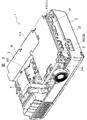
光源冷却系Dでは、光源装置411の前面側に配置された軸流ファン7と、この軸流ファン7に取り付けられたダクト64とが用いられている。
光源冷却系Dでは、電源冷却系Cおよび偏光変換素子冷却系Bから排気された空気は、軸流ファン7の吸引によって、光源装置411の側面部分に形成されたスリット状の開口から光源装置411内に入り込んで光源ランプ416を冷却し、ダクト64を介して、外装ケース2の排気口222から外部へと排気される。
In the light source cooling system D, an
In the light source cooling system D, the air exhausted from the power source cooling system C and the polarization conversion element cooling system B is sucked by the
〔4.軸流ファンの構造〕
次に、軸流ファン7について説明する。図10及び図11に軸流ファン7を示す。この軸流ファン7は、軸流ファン本体70と、この軸流ファン本体70を収納するフレーム71と、このフレーム71に取り付けられたカバー72とを備える。
図11及び図12に示すように、軸流ファン本体70は、主軸701と、ケーシング700と、ケーシング700を介して主軸701の外周面に取り付けられた複数枚、例えば、7枚の主翼702と、各主翼702間に配置された補助翼703と、主軸701を駆動するモータ73とを備えている。
[4. (Axial flow fan structure)
Next, the
As shown in FIGS. 11 and 12, the
ケーシング700は、円筒状であり、一方の端面が開口している。このケーシング700内には、主軸701及びモータ73が収容されている。
モータ73は、ケーシング700の内側に設けられた円筒状のステータ734と、ステータ734の内周面に固定された磁石731と、この磁石731に対向配置された磁石732と、基板735とを備える。磁石732の周囲にはコイル733が巻回されている。基板735上には、図示しないがモータ駆動用のICや回路等が実装されており、コイル733に流れる電流が制御されている。
主軸701は、その先端がステータ734の内側に固定され、このステータ734及びケーシング700を支持している。
The
The
The
流体軸受け704は、主軸701を回転可能に支持するものであり、主軸701が挿入される軸受け孔704A1が形成された円筒状の本体704Aと、この本体704Aに形成された台部704Bとを備える。本体704Aの軸受け孔704A1には、潤滑剤としての流体が注入されている。
主翼702及び補助翼703は、主軸701の軸方向に対して傾斜して設けられている。図14に示すように、主軸701に垂直な面に対する補助翼703の取付角度をθ2、主軸701に垂直な面に対する主翼702の取付角度をθ1とした場合、θ2は、θ1−10°以上、θ1+5°以下となっている。なかでも、θ2=θ1+5°が好ましい。主翼702の主軸701に沿った断面形状は、流線形状となっている。
なお、主軸701を駆動させると、気体は、図11の矢印P方向に流れ、主翼702の回転方向前縁が吸気側、回転方向後縁が排気側となる。
The
The
When the
図12に示すように、主翼702の正圧面(軸流ファン7内を流れる気体により圧力がかかる面)702A及び負圧面(前記正圧面702Aと反対側の面)702Bには、光沢面702Cが形成されている。この光沢面702Cは、正圧面702A及び負圧面702Bの中心から、回転方向後縁に向かって形成されている。この光沢面702Cは、正圧面702A及び負圧面702Bを直接、磨くことで形成してもよく、また、光沢のあるシールを貼り付けることで形成してもよい。
さらに、図13に示すように、主翼702は、隣接する主翼702が排気側から見た際に、例えば1mm程度重なり合うように配置されている。
また、図14に示すように、主翼702は、回転方向に沿ってピッチ寸法(主翼702の回転方向前端部間の寸法)Wで等間隔に配置されている。このピッチ寸法Wは、例えば18.7mmである。また、主翼702の回転方向後端部から回転方向前端部までの主軸701の軸方向に沿った高さ寸法H1は、例えば13.6mmである。
さらに、主翼702の主軸701の軸方向に沿った断面の厚さ寸法T1は、例えば、1.2mmである。
As shown in FIG. 12, a glossy surface 702C is provided on the positive pressure surface (surface to which pressure is applied by the gas flowing in the axial fan 7) 702A and the negative pressure surface (surface opposite to the
Furthermore, as shown in FIG. 13, the
Further, as shown in FIG. 14, the
Furthermore, the thickness dimension T1 of the cross section along the axial direction of the
補助翼703は、主翼702の相似形状となっている。補助翼703の回転方向後端部から回転方向前端部までの主軸701の軸方向に沿った高さ寸法H2は、H1の約3/4であり、例えば9.8mmである。また、回転方向に沿ってX軸を設定した場合、X軸に対する補助翼703の回転方向前端部の位置と、反回転方向に隣接する主翼702の回転方向前端部の位置とは一致している。
さらに、補助翼703の回転方向後端部は、反回転方向に隣接する主翼702の回転方向後端部から回転方向(X軸の+方向)にWb、例えば、W/2離れている。すなわち、補助翼703は、互いに隣接する主翼702間の略中央に設けられていることとなる。
また、補助翼703の主軸701の軸方向に沿った断面の厚さ寸法T2は、主翼702の前記断面の厚さ寸法T1よりも小さくなっており、例えば、1.0mmである。
The
Further, the rear end portion in the rotation direction of the
Further, the thickness T2 of the cross section along the axial direction of the
図11及び図15に示すように、フレーム71は、アルミニウム、マグネシウム等の金属製であり、その外径は、例えば、50mm以下である。フレーム71は、その吸気側及び排気側の端面が開口した円筒形状のフレーム本体711と、4個の固定部712とを備えている。
固定部712は、フレーム本体711の排気側の開口周縁からフレーム本体711の外方に向かって延びている。固定部712には、ねじ止め用の孔712Aが形成されており、この固定部712にダクト64がねじ止めされることとなる。
フレーム本体711の内周側と、主翼702との間には、0.5mm以下、好ましくは、0.3mm以下の隙間が形成されている。
As shown in FIGS. 11 and 15, the
The fixing
A gap of 0.5 mm or less, preferably 0.3 mm or less is formed between the inner peripheral side of the
また、フレーム本体711の排気側の開口には、モータ73を保持するスポーク713が設けられている。このスポーク713は、フレーム本体711の排気側の開口周縁から開口の略中心に向かって延びており、フレーム本体711の開口の略中心に配置された台座714に一体成形されている。この台座714上にモータ73が載置される。さらに、この台座714の略中央部分には、段部714Aが形成された孔714Bが形成されており、この孔714Bの段部714Aに流体軸受け704の台部704Bが係合する。
スポーク713は、主翼702の回転方向と反対方向に湾曲し、主翼702により送気された空気をすくい上げるような曲面が形成されている。これにより、スポーク713は、主翼702により送気された空気をフレーム本体711の外部へ排気するための導翼としての役割を果たすこととなる。
また、スポーク713と、主翼702の回転方向後縁との間には約5mm以下の隙間が形成されている。
このようなスポーク713は、例えば4本設けられており、主翼702の数からスポーク713の数を引いた数が奇数となっている。
A spoke 713 that holds the
The
Further, a gap of about 5 mm or less is formed between the
For example, four
一方、図16に示すように、フレーム本体711の吸気側の開口には、吸気側の開口を覆うようにフィルタ715が取り付けられている。フィルタ715は、フレーム本体711の吸気側の開口との間に所定の間隔をあけて配置されている。例えば、フィルタ715と、フレーム本体711の吸気側の開口との間に3mm前後の隙間を形成する。
フィルタ715は、SUSやアルミニウム等の金属板や樹脂板を部分的に接着し、積層した後、これを金属板または樹脂板の直交方向に引っ張る方法や金属板をエッチングする方法により得られる。
フィルタ715としては、例えば、図16及び図17(A)に示すような、フィルタ715Aが挙げられる。このフィルタ715Aは、金属板等をエッチングすることにより得られたものであり、開口形状が正六角形形状である。
本実施形態では、開口が正六角形状のフィルタ715Aを採用したが、これに限らず、例えば、図17(B)〜(D)にあげるようなものも採用できる。
図17(B)に示すようなフィルタ715Bは、SUS等の金属や、耐熱樹脂製のワイヤを平織りしたものであり、開口形状が四角形状となっている。
さらに、図17(C)に示すようなフィルタ715Cは、いわゆるハニカムメッシュと呼ばれるフィルタであり、フィルタ715Cの開口形状は、六角形形状である。
また、図17(D)に示すようなフィルタ715Dは、板状の材料に略円形形状の孔をあけたものである。
On the other hand, as shown in FIG. 16, a filter 715 is attached to the intake side opening of the
The filter 715 is obtained by partially bonding and laminating a metal plate such as SUS or aluminum or a resin plate and then pulling it in a direction orthogonal to the metal plate or the resin plate or by etching the metal plate.
An example of the filter 715 is a filter 715A as shown in FIGS. 16 and 17A. The filter 715A is obtained by etching a metal plate or the like, and the opening shape is a regular hexagonal shape.
In the present embodiment, the regular hexagonal filter 715A is employed, but the present invention is not limited to this, and for example, those shown in FIGS. 17B to 17D can be employed.
A filter 715B as shown in FIG. 17B is a flat weave of a metal such as SUS or a wire made of heat-resistant resin, and has an opening shape of a square shape.
Further, a filter 715C as illustrated in FIG. 17C is a so-called honeycomb mesh filter, and the opening shape of the filter 715C is a hexagonal shape.
Further, a filter 715D as shown in FIG. 17D is a plate-shaped material having a substantially circular hole.
以上のような、フィルタ715(715A〜715D)の厚さ寸法Tは、好ましくは0.1mm以上、5mm以下であり、特に好ましくは3mm以下である。開口径Rは0.3mm以上、3mm以下が好ましく、開口率Qは、70%以上、90%以下が好ましい。また、開口を形成する枠の幅FWは、特に限定されない。
なお、フィルタ715Aでは、開口径Rは、0.3mm程度が特に好ましく、フィルタ715Bでは、開口径Rは1.2mm程度が特に好ましい。
また、ここでは、開口の形状が六角形、四角形、円形のものを例示したが、これに限らず、他の形状、例えば、六角形、四角形以外の多角形等であってもよい。
The thickness dimension T of the filter 715 (715A to 715D) as described above is preferably 0.1 mm or more and 5 mm or less, and particularly preferably 3 mm or less. The opening diameter R is preferably 0.3 mm or more and 3 mm or less, and the opening ratio Q is preferably 70% or more and 90% or less. Further, the width FW of the frame forming the opening is not particularly limited.
In the filter 715A, the opening diameter R is particularly preferably about 0.3 mm, and in the filter 715B, the opening diameter R is particularly preferably about 1.2 mm.
In addition, here, the shape of the opening is exemplified as a hexagonal shape, a quadrangular shape, or a circular shape. However, the shape is not limited to this, and other shapes such as a polygonal shape other than a hexagonal shape or a rectangular shape may be used.
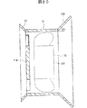
次に、図10に戻って、フレーム本体711の排気側に取り付けられた筒状のカバー72について説明する。カバー72は、樹脂または金属製であり、送気方向に向かって径が大きくなるテーパー形状となっている。カバー72の主軸701の軸方向に沿った長さ寸法は、2〜5mm程度である。このカバー72の略中央には、平面略円形形状の支持部720が設置されている。また、このカバー72の内部には、ルーバ721が取り付けられている。
ルーバ721は、カバー72の中心に設置された支持部720からカバー72周縁に向かって延びるとともに、等間隔で配置された複数枚のルーバ部材722を備えている。図18にも示すように、このルーバ部材722は、主翼702の傾斜方向と反対方向に傾斜し、主翼702の回転方向と反対方向に湾曲している。そのため、主翼702間から漏れた光Pは、ルーバ部材722に当たることとなる。
Next, returning to FIG. 10, the
The
また、ルーバ部材722には、主翼702により送気された空気をすくい上げるような曲面が形成されている。さらに、ルーバ部材722の主軸701の軸方向に沿った方向の断面形状は、流線形状となっている。これにより、ルーバ部材722は、主翼702により送気された空気をフレーム71の外部へ排気する導翼としての役割を果たすこととなる。
また、ルーバ部材722と、フレーム本体711との間には、例えば、0.5〜2mmの隙間が形成されている。ルーバ部材722の本数は、主翼702の本数の2倍であり、本実施形態では主翼702は7枚であるため、ルーバ部材722は14本となる。
The
In addition, a gap of 0.5 to 2 mm is formed between the
従って、本実施の形態によれば、以下のような効果を奏することができる。
(1-1) 補助翼703を設けることで、軸流ファン7の中を流れる気体の速度が向上し、速度が均一化するため、乱流の発生が防止できる。そのため、高い回転数で軸流ファン7を回転させた場合であっても、乱流と主翼702及び補助翼703とがぶつかることにより発生する騒音を低減でき、高静圧かつ低騒音の軸流ファン7とすることができる。
(1-2) また、補助翼703の高さ寸法H2を主翼702の高さ寸法H1の約3/4とし、X軸に対する補助翼703の回転方向前端部の位置と、反回転方向に隣接する主翼702の回転方向前端部の位置とを一致させることで、乱流の発生をより効果的に防止できる。
(1-3) さらに、補助翼703を設けることで、主翼702間の隙間から漏れる光の量を少なくすることができる。
Therefore, according to the present embodiment, the following effects can be obtained.
(1-1) By providing the
(1-2) Further, the height H2 of the
(1-3) Furthermore, by providing the
(1-4) 補助翼703の回転方向後端部と、反回転方向に隣接する主翼702の回転方向後端部との距離WbをW/2とすることで、より効果的に、軸流ファン7の中を流れる気体の速度を均一化でき、乱流の発生を抑制できる。
(1-5) 補助翼703の取付角度θ2を最大で主翼702の取付角度θ1+5°とし、補助翼703と反回転方向に隣接する主翼702と間を狭めることで、空気の流速を高め、流れを整えることができる。これにより、効果的に乱流の発生が防止でき、低騒音化を図ることができる。
(1-6) 主翼702及び補助翼703の主軸701の軸方向に沿った断面形状を流線形状としたため、軸流ファン7の中を流れる空気と、主翼702、補助翼703との間の抵抗を少なくすることができ、騒音の発生を低減できる。
(1-4) By setting the distance Wb between the rotation direction rear end of the
(1-5) The attachment angle θ 2 of the
(1-6) Since the cross-sectional shape along the axial direction of the
(1-7) 補助翼703の断面の厚さ寸法を主翼702の断面の厚さ寸法以下とすることで、さらに効果的に乱流の発生を防止できる。
(1-8) 排気側から見た際に、隣接する主翼702同士が重なるように配置することで、主翼702間の隙間からの光の漏れを略確実に防止できる。
(1-9) 主翼702の正圧面702A及び負圧面702Bに光沢面702Cを形成したため、空気が主翼702に当たる際の気流の剥離を少なくできる。従って、乱流の発生を略確実に防止でき、軸流ファン7の低騒音化を図ることができる。
(1-7) By setting the thickness dimension of the cross section of the
(1-8) By arranging the adjacent
(1-9) Since the glossy surface 702C is formed on the
(1-10) フレーム本体711の排気側の開口周縁に取り付けられるスポーク713を主翼702の回転方向と反対方向に湾曲させ、さらに主翼702により送気された空気をすくい上げるような曲面を形成したので、スポーク713は、導翼としての役割を果たすこととなり、よりスムーズに空気を排気することが可能となる。従って、排気される空気とスポーク713とがぶつかり合うことによって発生する騒音を低減することができる。
(1-11) 主翼702の数からスポーク713の数を引いた数を奇数としたので、共鳴が防止され、騒音を低減させることができる。
(1-12) フレーム71を熱伝導性の低い部材で成形した場合には、放熱しにくいため、主軸701を駆動するコイル733の熱により、モータ73のコイル733及び基板735上のモータ駆動用のICが損傷してしまうという問題がある。
これに対し、本実施形態では、フレーム71を金属製としたので、放熱性を向上させることができ、コイル733及びモータ駆動用のICが熱により影響を受けてしまうことを防止できる。従って、軸流ファン7の耐久性も向上できる。
(1-10) The
(1-11) Since the number obtained by subtracting the number of
(1-12) When the
On the other hand, in this embodiment, since the
(1-13) また、フレーム71を金属製としたので、フレーム71の剛性と精度を確保できる。
(1-14) さらに、フレーム71を金属製とすることで、フレーム71をリサイクルすることも可能となり、環境に対応したものとすることができる。
(1-15) フレーム本体711の内周側と、主翼702との間の隙間を0.5mm以下とすることで、高静圧化することができる。これにより、軸流ファン7を高い回転数で回転させる必要がなくなるので、さらなる低騒音化を図ることができる。
(1-13) Since the
(1-14) Furthermore, since the
(1-15) By setting the gap between the inner peripheral side of the frame
(1-16) フレーム本体711の開口縁全周に沿ってフランジを設け、このフランジにねじ孔を形成してもよいが、この場合には開口縁全周に沿ってフランジが設けられているので、軽量化を図ることが難しい。これに対し、本実施形態では、フレーム本体711の開口縁全周にフランジを形成せず、固定部712のみを開口周縁に設けたので、フレーム71の軽量化を図ることができる。
(1-17) フィルタ715を設けない場合には、軸流ファン7の強い吸気力により、あらゆる方向から空気が吸気されるため、乱流が生じ騒音が発生しやすい。これに対し、本実施形態のような正六角形形状の開口が形成されたフィルタ715を設けることで、軸流ファン7に吸気される空気の方向を揃えることができ、騒音を低減させることができる。さらに、フィルタ715と、フレーム本体711の開口との間には隙間が形成されているので、より効果的に騒音を低減できる。
(1-18) また、フィルタ715の開口をハニカム形状としてもよいが、ハニカム形状とした場合には、開口が崩れやすいという問題がある。これに対し、本実施形態では、正六角形状の開口を備えたフィルタ715Aを採用したので、ハニカム形状に比べて開口が崩れにくい。そのため、騒音低減効果を確実に発揮することができる。
なお、開口が四角形状のフィルタ715Bを採用した場合にも、同様の効果を奏することができる。
(1-16) A flange may be provided along the entire circumference of the opening edge of the
(1-17) When the filter 715 is not provided, air is sucked in from all directions due to the strong intake force of the
(1-18) Further, the opening of the filter 715 may be formed in a honeycomb shape. However, when the filter 715 is formed in a honeycomb shape, there is a problem that the opening tends to collapse. On the other hand, in this embodiment, since the filter 715A having a regular hexagonal opening is employed, the opening is less likely to collapse than the honeycomb shape. Therefore, the noise reduction effect can be exhibited reliably.
Note that the same effect can be obtained when the filter 715B having a square opening is employed.
(1-19)フィルタ715の開口径Rが0.3mm未満である場合や、開口率が70%未満である場合には、気体の通りが悪くなり、流量が低下する虞がある。また、3mmよりも大きいと、気体の流れを揃えることが困難となる虞がある。さらに、開口率を90%を超えるものとした場合にはフィルタの加工性が低下する可能性がある。
本実施形態では、フィルタ715の開口径Rを0.3mm〜3mmとし、開口率Qを70以上、90%以下としたので、このような問題は生じない。
(1-20) フレーム本体711の排気側に取り付けられたカバー72には、導翼となるルーバ721が設けられているので、排気される空気を整流することができる。従って、乱流の発生を防止でき、さらなる低騒音化を図ることができる。また、ルーバ721と、フレーム本体711の開口との間には隙間が形成されているので、より一層の低騒音化を図ることができる。
(1-21) カバー72の主軸701の軸方向に沿った長さ寸法を長くするほど、ルーバ部材722の取付角度(主軸701の軸方向に対するルーバ部材722の傾斜角度)を大きくすることができ、ルーバ部材722を俳気される空気の流れに沿った方向に延びるものとすることができるため、ルーバ部材722と、排気される空気との間に生じる抵抗を小さくできる。従って、カバー72の主軸701の軸方向に沿った長さ寸法を長くすることが好ましいが、長くしすぎると、軸流ファン7にダクト64を取り付けることが困難となる。本実施形態では、カバー72の主軸701の軸方向に沿った長さ寸法は、2〜5mm程度としたので、排気される空気との抵抗を抑えることができ、かつ、ダクト64の取付けも容易に行うことができる。
(1-19) When the opening diameter R of the filter 715 is less than 0.3 mm, or when the opening ratio is less than 70%, there is a possibility that the flow of gas becomes worse and the flow rate decreases. Moreover, when larger than 3 mm, there exists a possibility that it may become difficult to arrange the flow of gas. Furthermore, when the aperture ratio exceeds 90%, the processability of the filter may be reduced.
In this embodiment, since the opening diameter R of the filter 715 is 0.3 mm to 3 mm and the opening ratio Q is 70 or more and 90% or less, such a problem does not occur.
(1-20) The
(1-21) As the length of the
(1-22) ルーバ部材722を主翼702の傾斜方向と反対方向に傾斜して配置し、かつ、ルーバ部材722の本数を主翼702の二倍とすることで、主翼702間及び主翼702と補助翼703間から漏れる光Pを遮断することができる(図18参照)。従って、ユーザに光漏れによる不快感を与えず、使用しやすいプロジェクタ1とすることができる。
(1-23) 軸流ファンの軸受けは、ボールベアリングを採用することが一般的であるが、ボールベアリングを採用した場合には、主軸701の回転に伴って擦過音が発生しやすい。これに対し、本実施形態では流体軸受け704としているため、主軸701の回転に伴う擦過音の発生を防止でき、低騒音化を図ることができる。
(1-22) By arranging the
(1-23) A ball bearing is generally used for the bearing of the axial fan. However, when a ball bearing is used, a rubbing noise is likely to occur as the
2.第2実施形態
次に、本発明の第2実施形態を説明する。尚、以下の説明では、既に説明した部分と同一の部分については、同一符号を付してその説明を省略する。
第1実施形態では、フレーム本体711の吸気側の開口にフィルタ715を取り付けたが、本実施形態では、図19に示すように、整流板716が取り付けられている。この整流板716は、反送気方向に向かって径が大きくなるテーパー形状となっている。
図20に示すように、整流板716の主軸701に対する傾斜角度θ3は、例えば、45°となっている。
また、整流板716の主軸701の軸方向の長さ寸法は、例えば、1.5〜10mm以下となっている。
なお、この整流板716の吸気口に前記第1実施形態と同様のフィルタ715を装着することも可能である。このようにフィルタ715を設けることで、軸流ファン7に吸気される空気の方向を揃えることができ、騒音を低減させることができる。
2. Second Embodiment Next, a second embodiment of the present invention will be described. In the following description, the same parts as those already described are denoted by the same reference numerals and the description thereof is omitted.
In the first embodiment, the filter 715 is attached to the intake-side opening of the
As shown in FIG. 20, the inclination angle θ 3 of the rectifying
Moreover, the length dimension of the axial direction of the main axis |
Note that a filter 715 similar to that of the first embodiment may be attached to the intake port of the rectifying
また、第1実施形態では、ルーバ721は、カバー72の中心から周縁に向かって延びる複数枚のルーバ部材722を備えているとした。これに対し、本実施形態では、図21及び図22に示すように、ルーバ部材723は、所定の間隔で略平行に配置されている。このルーバ部材723は、図22奥側に傾斜している。
なお、図22においては、ルーバ部材723と、ルーバ部材723間の隙間とを明確にするため、ルーバ部材723に斜線を施している。
In the first embodiment, the
In FIG. 22, the
このような本実施形態によれば、第1実施形態の(1-1)〜(1-16)、(1- 21)、(1- 23)と同様の効果を奏することができる他、以下の効果を奏することができる。
(2-1) 整流板716を設けない場合には、軸流ファン7の強い吸気力により、あらゆる方向から空気が吸気されるため、乱流が生じ騒音が発生しやすい。これに対し、本実施形態のように、テーパー形状の整流板716を設けることで、軸流ファン7に吸気される空気の方向を揃えることができ、騒音を低減させることができる。
さらに、整流板716の吸気口にフィルタ715を装着することで、整流板716の騒音低減効果に加え、フィルタ715の騒音低減効果を得ることができ、軸流ファン7のより一層の騒音低減を可能にすることができる。
(2-2) また、整流板をフレーム本体711の開口と同じ径のものとした場合には、整流板が吸気の流れを阻害することとなるため、充分な騒音低減効果が得られない。本実施形態では、整流板716をテーパー形状としたので、整流板716により吸気の流れが阻害されることがなく、充分に騒音を低減できる。
According to this embodiment, the same effects as (1-1) to (1-16), (1-21), and (1-23) of the first embodiment can be obtained, and the following The effect of can be produced.
(2-1) When the rectifying
Further, by attaching the filter 715 to the air inlet of the rectifying
(2-2) Further, when the rectifying plate has the same diameter as the opening of the frame
(2-3)本実施形態では、ルーバ部材723を略平行に配置しているため、ルーバ部材723の設置を容易に行うことができる。
(2-3 ) In this embodiment, since the
なお、本発明は前述の実施の形態に限定されるものではなく、本発明の目的を達成できる範囲での変形、改良等は本発明に含まれるものである。
例えば、前記実施形態では、フレーム本体711にカバー72を取り付けていたが、カバー72を外装ケース2に取り付けてもよい。ただし、外装ケース2にカバー72を取り付けた場合には、軸流ファン7の設置位置がずれることにより、カバー72内のルーバ部材722,723と、主翼702及び補助翼703との位置関係がずれてしまうこととなる。そのため、ルーバ部材722,723の遮光効果が充分に発揮できない可能性があり、これを改善する構造を考慮する必要がある。
これに対し、フレーム本体711にカバー72を取り付けた場合には、例え、軸流ファン7の設置位置がずれてしまっても、ルーバ部材722,723と、主翼702、補助翼703と間には、ずれが生じないので、効果的に光漏れを防止できる。さらに、排気側から見たカバーの平面形状は、前記実施形態のような円形形状に限らず、例えば、矩形形状であってもよい。
It should be noted that the present invention is not limited to the above-described embodiment, but includes modifications and improvements as long as the object of the present invention can be achieved.
For example, in the embodiment, the
On the other hand, when the
さらに、第1実施形態では、フィルタ715の厚さ寸法は、0.1〜5mmとしたが、この範囲には限られない。
また、第1実施形態では、フィルタ715の開口は正六角形としたが、円形形状であってもよい。また、フィルタは、SUS等の金属や、耐熱性樹脂材のワイヤーを平織りした矩形の開口を有する部材であってもよい。
さらに、フィルタ715の開口径Rを、0.3mm以上、3mm以下としたが、この範囲内には限られない。また、開口率は70〜90%としたが、この範囲には限られず、例えば、50〜95%の範囲内であってもよい。
さらに、第1実施形態では、フィルタ715のみを取付け、整流板716は取り付けていなかったが、整流板716を取り付けてもよい。整流板716及びフィルタ715の双方を取り付けることで、さらなる低騒音化を図ることができる。
Furthermore, in the first embodiment, the thickness dimension of the filter 715 is 0.1 to 5 mm, but is not limited to this range.
In the first embodiment, the opening of the filter 715 is a regular hexagon, but may be a circular shape. Further, the filter may be a member having a rectangular opening obtained by plain weaving a metal such as SUS or a wire of a heat resistant resin material.
Furthermore, although the opening diameter R of the filter 715 is 0.3 mm or more and 3 mm or less, it is not limited to this range. Moreover, although the aperture ratio was 70 to 90%, it is not limited to this range, and may be in the range of 50 to 95%, for example.
Further, in the first embodiment, only the filter 715 is attached and the rectifying
また、第2実施形態では整流板716の主軸701に対する傾斜角度θ3を45°としたが、この角度には限らず、θ3は、30°〜90°の範囲であればよい。30°〜90°であれば、整流板716により吸気の流れを阻害されることがなく、充分に騒音を低減できるからである。具体的なθ3の値は、対象となる軸流ファンのもつ静圧と、流量によって定まる主要流速のベクトルに適合させればよい。
さらに、前記実施形態では、フレーム71は、金属製としたが、これに限らず、熱伝導性の高い樹脂製としてもよい。この場合にも、金属製とした場合と同様、フレーム71の放熱性を向上できる。
また、前記実施形態では、スポーク713は、導翼としての役割を果たすものとしたが、単にモータ73を保持するだけのものであってもよい。この場合は、スポークを湾曲させたり、送気された気体をすくい上げるような曲面を形成したりする必要がないので、スポークの形成が容易となる。
さらに、主翼702の正圧面702A及び負圧面702Bに光沢面702Cが形成されているとしたが、光沢面702Cは形成されていなくてもよい。光沢面702Cを形成しなければ、主翼702の加工にかかる手間を省くことができる。
また、主翼702は排気側から見た際に、隣接する主翼702に重なり合う様に配置されているとしたが、例えば、カバー72のルーバ721のみで略完全に光漏れを防止できる場合には、主翼702同士を重なり合うように配置しなくてもよい。このようにすれば、主翼702の取付けを容易化できる。
In the second embodiment, the inclination angle θ 3 of the rectifying
Furthermore, in the said embodiment, although the flame |
Moreover, in the said embodiment, although the
Further, although the glossy surface 702C is formed on the
In addition, the
また、前記実施形態では、主翼702の厚さ寸法T1よりも補助翼703の厚さ寸法T2が小さいものとしたが、T2はT1と同じ厚さ寸法であってもよく、さらには、T1よりも大きくてもよい。
主軸701に垂直な面に対する補助翼703の取付角度をθ2、主軸701に垂直な面に対する主翼702の取付角度をθ1とした場合、θ2は、θ1−10°以上、θ1+5°以下、なかでもθ2=θ1+5°が好ましいとしたが、この角度には限られず、騒音低減効果が発揮できる範囲内であればよい。
前記実施形態では、主翼702及び補助翼703の主軸701の軸方向に沿った断面形状は流線形状であるとしたが、これに限らず、単なる矩形形状としてもよい。ただし、この場合、空気との抵抗が大きくなってしまうため、流線形状にした場合に比べ、低騒音効果が低減する可能性もある。
In the above embodiment, the thickness dimension T2 of the
Mounting angle theta 2 aileron 703 against a plane perpendicular to the
In the embodiment, the cross-sectional shape along the axial direction of the
さらに、補助翼703の回転方向後端部は、反回転方向に隣接する主翼702の回転方向後端部からW/2離れた位置としたが、これに限らず、例えば、1/4W離れた位置としてもよい。
補助翼703の回転方向前端部のX軸に対する位置は、反回転方向に隣接する主翼702の回転方向前端部と一致しているとしたが、これに限らず、補助翼703の回転方向前端部は、主翼702の回転方向前端部から−1/8Wから+1/8Wの範囲内にあればよい。また、補助翼703の高さ寸法は主翼702の高さ寸法の3/4としたが、1/2〜4/5の範囲内であればよい。以上のような範囲内であれば、騒音を低減させることが可能だからである。ただし、前記実施形態のように、補助翼703の高さ寸法を主翼702の高さ寸法の約3/4とし、補助翼703の回転方向前端部と、反回転方向に隣接する主翼702の回転方向前端部とを一致させた場合に、最も高い騒音低減効果を発揮できる。
Further, the rear end portion in the rotation direction of the
Although the position of the front end portion in the rotational direction of the
[実施例]
本発明の効果を確認するために以下の実験を行った。
[補助翼と主翼との関係]
充分な気体の流量を確保し、かつ、低騒音化を図るための補助翼と主翼との関係を確認するために以下のような実験を行った。
主翼702及び補助翼703の形状及び配置を仮定し、軸流ファン内に流入した気体における主翼702及び補助翼703の周辺の乱流エネルギーの発生状況をシミュレーションした。
ここで、乱流エネルギーとは、一般的に慣性抵抗と言われるもので、速度の2乗で表される。慣性抵抗(圧力抵抗ともいう)は、流体が物体に衝突し速度を変えられるときの反作用として現れる抵抗であり、流体が物体表面に働く法線応力を意味する。また、ファンの翼壁面(主翼702の表面及び補助翼703の表面)の圧力変動からCurleの式を用いて騒音レベルを算出する方法は一般的に行なわれている。したがって、ファンの翼壁面の圧力変動より騒音レベルを算出できることから、今回の実験では、翼壁面に働く法線応力を意味する乱流エネルギーの発生状況より騒音レベルを判定した。
[Example]
In order to confirm the effect of the present invention, the following experiment was conducted.
[Relationship between auxiliary wing and main wing]
In order to ensure a sufficient gas flow rate and to reduce the noise, the following experiment was conducted to confirm the relationship between the auxiliary wing and the main wing.
Assuming the shape and arrangement of the
Here, turbulent energy is generally referred to as inertial resistance and is represented by the square of velocity. Inertial resistance (also referred to as pressure resistance) is resistance that appears as a reaction when a fluid collides with an object and changes its speed, and means normal stress that acts on the object surface. In general, a method for calculating the noise level using the Curle's formula from pressure fluctuations on the blade wall surfaces of the fan (the surface of the
まず、軸流ファンが所望の空気流を発生させた場合における軸流ファンへの空気導入の条件を測定し、この測定結果から、軸流ファンへの気体の流入の条件を算出した。これにより、流入角60°、流入速3.2m/secとなった。
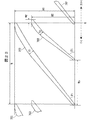
また、主翼702の高さ寸法H1を13.6mm、ピッチ寸法Wを18.7mm、取付角度θ1を40°、主翼702の厚さ寸法T1を1.2mmとした。補助翼703の厚さ寸法T2は、1.0mmとする。また、図23に示すように、軸流ファンの回転方向に沿ってX軸を設定し、回転方向を+、反回転方向を−とした。また、補助翼703の回転方向前端部から、この補助翼703の反回転方向に隣接する主翼702の回転方向前端部までのX軸上の寸法をWfとし、補助翼703の反回転方向に隣接する主翼702の回転方向後端部から、補助翼703の回転方向後端部までのX軸上の寸法をWbとした。
First, the conditions for introducing air into the axial fan when the axial fan generated a desired air flow were measured, and the conditions for the gas flow into the axial fan were calculated from the measurement results. As a result, the inflow angle was 60 ° and the inflow speed was 3.2 m / sec.
In addition, the height dimension H1 of the
(1)補助翼703の高さ寸法H2と、乱流エネルギーとの関係
Wfを0とし、Wbを約W/2、すなわち、9.4mmとした。
(実施例1-1)
H2の寸法を6.8mm(H1の約1/2)とした。
(実施例1-2)
H2の寸法を9.1mm(H1の約2/3)とした。
(実施例1-3)
H2の寸法を9.8mm(H1の約3/4)とした。
(実施例1-4)
H2の寸法を10.9mm(H1の約4/5)とした。
(比較例1-1)
H2の寸法を3.4mm(H1の1/4)とした。
(比較例1-2)
H2の寸法を11.3mm(H1の5/6)とした。
実施例1-1〜1-4、比較例1-1、1-2の結果を表1に示す。
(1) Relationship between the height dimension H2 of the
(Example 1-1)
The dimension of H2 was set to 6.8 mm (about 1/2 of H1).
(Example 1-2)
The dimension of H2 was set to 9.1 mm (about 2/3 of H1).
(Example 1-3)
The dimension of H2 was 9.8 mm (about 3/4 of H1).
(Example 1-4)
The dimension of H2 was 10.9 mm (approximately 4/5 of H1).
(Comparative Example 1-1)
The dimension of H2 was 3.4 mm (1/4 of H1).
(Comparative Example 1-2)
The dimension of H2 was set to 11.3 mm (5/6 of H1).
The results of Examples 1-1 to 1-4 and Comparative Examples 1-1 and 1-2 are shown in Table 1.

実施例1-1〜1-4では、何れも1.9m2/sec2以上の乱流エネルギーの発生箇所が1箇所以下であり、騒音を低減できることが確認された。なかでも、実施例1-3(H2=9.8mm)では1.9m2/sec2以上の乱流エネルギーは発生せず、最も高い騒音低減効果を得ることができることが確認された。
一方、比較例1-1,1-2では、1.9m2/sec2以上の乱流エネルギーの発生箇所が2箇所以上であり、騒音低減効果を確認することができなかった。
以上より、補助翼703の高さ寸法H2は、主翼702の高さ寸法H1の1/2以上、4/5以下であれば、騒音低減効果を得ることができることが確認された。
In each of Examples 1-1 to 1-4, the number of occurrences of turbulent energy of 1.9 m 2 / sec 2 or more was 1 or less, and it was confirmed that noise could be reduced. Especially, in Example 1-3 (H2 = 9.8 mm), turbulent energy of 1.9 m 2 / sec 2 or more was not generated, and it was confirmed that the highest noise reduction effect can be obtained.
On the other hand, in Comparative Examples 1-1 and 1-2, there were two or more turbulent energy generation locations of 1.9 m 2 / sec 2 or more, and the noise reduction effect could not be confirmed.
From the above, it was confirmed that the noise reduction effect can be obtained if the height dimension H2 of the
(2)補助翼703の回転方向前端部の位置と、乱流エネルギーの発生との関係
補助翼703の回転方向前端部の位置と、乱流エネルギーの発生との関係について調べた。Wbを約W/2、すなわち9.4mmとし、補助翼703の高さ寸法H2を、主翼702の高さ寸法H1の約1/2、すなわち6.8mmとした。
なお、補助翼の反回転方向に隣接する主翼の回転方向前端部の位置を0とし、X軸上における回転方向を+、反回転方向を−としている。
(実施例2-1)
Wfを−2.3mm(−1/8W)とした。
(実施例2-2)
Wfを−2.1mm(−1/9W)とした。
(実施例2-3)
Wfを0mmとした。
(実施例2-4)
Wfを+2.1mm(+1/9W)とした。
(実施例2-5)
Wfを+2.3mm(+1/8W)とした。
(比較例2-1)
Wfを−2.7mm(−1/7W)とした。
(比較例2-2)
Wfを+2.7mm(+1/7W)とした。
実施例2-1〜2-5、比較例2-1、2-2の結果を表2に示す。
(2) Relationship between the position of the front end portion in the rotation direction of the
The position of the front end of the main wing adjacent to the counter-rotation direction of the auxiliary wing is 0, the rotation direction on the X axis is +, and the counter-rotation direction is-.
(Example 2-1)
Wf was set to -2.3 mm (-1/8 W).
(Example 2-2)
Wf was set to -2.1 mm (-1/9 W).
(Example 2-3)
Wf was set to 0 mm.
(Example 2-4)
Wf was set to +2.1 mm (+1/9 W).
(Example 2-5)
Wf was set to +2.3 mm (+1/8 W).
(Comparative Example 2-1)
Wf was set to -2.7 mm (-1/7 W).
(Comparative Example 2-2)
Wf was set to +2.7 mm (+1/7 W).
Table 2 shows the results of Examples 2-1 to 2-5 and Comparative Examples 2-1 and 2-2.
実施例2-1〜2-5では、何れも1.9m2/sec2以上の乱流エネルギーが発生した箇所は、1箇所以下であり、騒音低減効果を得ることができた。
一方、比較例2-1,2-2では、1.9m2/sec2以上の乱流エネルギーが発生した箇所が2箇所以上であり、騒音低減効果を得ることができなかった。以上より、主翼702のピッチ寸法Wの−1/8以上、1/8以下の範囲内であれば、騒音低減効果を得ることができることが確認された。
なお、実施例2-1〜2-5では、乱流エネルギーの発生状況に大差はなかった。従って、設計及び加工のしやすさを考慮すると、補助翼703の回転方向前端部の位置と、反回転方向に隣接する主翼702の回転方向前端部とを略一致させること(Wf=0)が好ましい。
このようにすることで、製造コストを低減し、かつ低騒音化を図ることができる。
In Examples 2-1 to 2-5, the number of locations where turbulent energy of 1.9 m 2 / sec 2 or more was generated was 1 or less, and a noise reduction effect could be obtained.
On the other hand, in Comparative Examples 2-1 and 2-2, there were two or more locations where turbulent energy of 1.9 m 2 / sec 2 or more was generated, and a noise reduction effect could not be obtained. From the above, it was confirmed that a noise reduction effect can be obtained if the pitch dimension W of the
In Examples 2-1 to 2-5, there was no significant difference in the state of turbulent energy generation. Therefore, in consideration of ease of design and processing, the position of the front end portion in the rotation direction of the
By doing in this way, manufacturing cost can be reduced and noise reduction can be achieved.
(3)補助翼703の回転方向後端部の位置と、乱流エネルギーの発生との関係
補助翼703の回転方向後端部の位置と、乱流エネルギーの発生との関係について調べた。
Wfを0とし、補助翼703の高さ寸法H2を主翼702の高さ寸法H1の約1/2、すなわち、6.8mmとした。
(実施例3-1)
Wbを9.4mm(1/2W)とした。
(実施例3-2)
Wbを7.4mm(2/5W)とした。
(実施例3-3)
Wbを4.7mm(1/4W)とした。
(比較例3-1)
Wbを12.5mm(2/3W)とした。
(比較例3-2)
Wbを11.4mm(3/5W)とした。
(比較例3-3)
Wbを3.7mm(1/3W)とした。
結果を表3に示す。
(3) Relationship between the position of the rear end of the
Wf was set to 0, and the height dimension H2 of the
(Example 3-1)
Wb was set to 9.4 mm (1/2 W).
(Example 3-2)
Wb was set to 7.4 mm (2/5 W).
(Example 3-3)
Wb was set to 4.7 mm (1/4 W).
(Comparative Example 3-1)
Wb was set to 12.5 mm (2/3 W).
(Comparative Example 3-2)
Wb was set to 11.4 mm (3/5 W).
(Comparative Example 3-3)
Wb was 3.7 mm (1/3 W).
The results are shown in Table 3.
実施例3-2、実施例3-3では、何れも1.9m2/sec2以上の乱流エネルギーが発生した箇所が1箇所以下であり、騒音低減効果を得ることができた。また、実施例3-1では、1.5m2/sec2以上、1.9m2/sec2未満の乱流エネルギーが発生した箇所が2箇所以下であり、1.9m2/sec2以上の乱流エネルギーは発生しなかった。実施例3-1のように、補助翼703を互いに隣接する主翼703間の略中央に設けた場合に、軸流ファン内を流れる空気の速度をより効果的に均一化でき、乱流の発生を防止できるため、より一層の騒音低減を図ることができることが確認された。
一方、比較例3-1〜3-3では、1.9m2/sec2以上の乱流エネルギーが2箇所以上で発生し、騒音低減効果を得ることができなかった。
以上より、補助翼703の回転方向後端部の位置が、主翼702の回転方向に沿ったピッチ寸法Wの1/2以下、1/4以上の範囲内であれば、騒音低減効果を得ることができることが確認された。
In Example 3-2 and Example 3-3, the number of locations where turbulent energy of 1.9 m 2 / sec 2 or more was generated was 1 or less, and a noise reduction effect could be obtained. Further, in Example 3-1, the number of places where turbulent energy of 1.5 m 2 / sec 2 or more and less than 1.9 m 2 / sec 2 was generated was 2 or less, and 1.9 m 2 / sec 2 or more. No turbulent energy was generated. When the
On the other hand, in Comparative Examples 3-1 to 3-3, turbulent energy of 1.9 m 2 / sec 2 or more was generated at two or more locations, and a noise reduction effect could not be obtained.
As described above, if the position of the rear end portion in the rotation direction of the
(4)補助翼703の取付角度θ2と、乱流エネルギーの発生との関係
Wfを0とし、Wbを1/2W、すなわち、9.4mmとした。
(実施例4-1)
取付角度θ2を30°(θ2=θ1−10°)とした。
(実施例4-2)
取付角度θ2を40°(θ2=θ1)とした。
(実施例4-3)
取付角度θ2を45°(θ2=θ1+5°)とした。
(比較例4-1)
取付角度θ2を20°(θ2=θ1−20°)とした。
(比較例4-2)
取付角度θ2を50°(θ2=θ1+10°)とした。
結果を表4に示す。
(4) The relationship Wf between the attachment angle θ 2 of the
(Example 4-1)
The mounting angle θ 2 was set to 30 ° (θ 2 = θ 1 −10 °).
(Example 4-2)
The mounting angle θ 2 was 40 ° (θ 2 = θ 1 ).
(Example 4-3)
The mounting angle θ 2 was 45 ° (θ 2 = θ 1 + 5 °).
(Comparative Example 4-1)
The mounting angle θ 2 was 20 ° (θ 2 = θ 1 −20 °).
(Comparative Example 4-2)
The mounting angle θ 2 was 50 ° (θ 2 = θ 1 + 10 °).
The results are shown in Table 4.
実施例4-1〜4-3では、何れも1.9m2/sec2以上の乱流エネルギーが発生した箇所が1箇所以下であり、騒音低減効果を得ることができた。なかでも、実施例4-3(取付角度θ2=45°)では、1.9m2/sec2以上の乱流エネルギーが発生した箇所は全くなく、最も高い騒音低減効果を得ることができた。
一方、比較例4-1,4-2では、1.9m2/sec2以上の乱流エネルギーが2箇所以上で発生し、騒音低減効果を得ることができなかった。
以上より、補助翼703の取付角度θ2が、θ1−10°以上、θ1+5°以下の範囲内であれば、騒音低減効果を得ることができることが確認された。
In Examples 4-1 to 4-3, the number of locations where turbulent energy of 1.9 m 2 / sec 2 or more was generated was 1 or less, and a noise reduction effect could be obtained. Especially, in Example 4-3 (mounting angle θ 2 = 45 °), there was no place where turbulent energy of 1.9 m 2 / sec 2 or more was generated, and the highest noise reduction effect could be obtained. .
On the other hand, in Comparative Examples 4-1 and 4-2, turbulent energy of 1.9 m 2 / sec 2 or more was generated at two or more locations, and a noise reduction effect could not be obtained.
From the above, it was confirmed that a noise reduction effect can be obtained if the attachment angle θ 2 of the
[フィルタと騒音との関係]
フィルタ715A、フィルタ715B、フィルタ715Cを用いて、軸流ファンのフレーム本体711の吸気側の開口に装着し、軸流ファンの騒音量及び軸流ファンに吸気される気体の速度(吸気流速度)を測定した。以下の実施例及び比較例における測定はすべて同じ条件のもと行われた。
(実施例5-1)
フィルタ715Aを使用し、開口径Rを0.30mm、開口を形成する枠の幅FWを0.04mm、開口率Qを78%とした。
(実施例5-2)
フィルタ715Bを使用し、開口径Rを1.2mm、開口を形成する枠の幅FWを0.30mm、開口率Qを70%とした。
(実施例5-3)
フィルタ715Cを使用し、開口径Rを0.87mm、開口を形成する枠の幅FWを0.02mm、開口率Qを81%とした。
(比較例5-1)
フィルタ715Bを使用し、開口径Rを0.32mm、開口を形成する枠の幅FWを0.10mm、開口率Qを58%とした。
(比較例5-2)
フィルタ715Bを使用し、開口径Rを5.50mm、開口を形成する枠の幅FWを0.80mm、開口率Qを76%とした。
(参考例)
フィルタ715を装着しなかった。
結果を表5に示す。
[Relationship between filter and noise]
The filter 715A, the filter 715B, and the filter 715C are attached to the opening on the intake side of the
(Example 5-1)
The filter 715A was used, the opening diameter R was 0.30 mm, the width FW of the frame forming the opening was 0.04 mm, and the opening ratio Q was 78%.
(Example 5-2)
The filter 715B was used, the opening diameter R was 1.2 mm, the width FW of the frame forming the opening was 0.30 mm, and the opening ratio Q was 70%.
(Example 5-3)
A filter 715C was used, the opening diameter R was 0.87 mm, the width FW of the frame forming the opening was 0.02 mm, and the opening ratio Q was 81%.
(Comparative Example 5-1)
The filter 715B was used, the opening diameter R was 0.32 mm, the width FW of the frame forming the opening was 0.10 mm, and the opening ratio Q was 58%.
(Comparative Example 5-2)
The filter 715B was used, the opening diameter R was 5.50 mm, the width FW of the frame forming the opening was 0.80 mm, and the opening ratio Q was 76%.
(Reference example)
Filter 715 was not attached.
The results are shown in Table 5.
実施例5-1〜5-3では、参考例のフィルタを装着しなかった軸流ファンと比較して騒音が10%以上低下し、かつ、吸気流速度の低下が5%未満であった。
一方、比較例5-1では、騒音は低下するものの、吸気流速度が大幅に低下した。開口率Qが70%未満の場合には、気体の流れが悪くなり流量が低下することが確認された。
また、比較例5-2では、開口径Rが3mmを超えており、気体の流れをそろえることが困難となったため、騒音低減効果を得ることができなかった。
以上より、開口径Rが0.3mm以上、3mm以下であり、開効率Qが70%以上であるフィルタが騒音を低減し、かつ吸気流速度を損なわないことが確認された。なかでも、フィルタの加工性を考慮すると、開効率Qは70%以上、90%以下が好ましい。
なお、実施例5-1〜5-3において、開口の形状による差がほとんど確認できなかったことから、開口径Rや開口率Qが上記範囲内であれば、開口形状が円形であるフィルタ715Dや、その他、四角形、六角形以外の形状であっても同様の効果を得ることができると考えられる。
In Examples 5-1 to 5-3, the noise was reduced by 10% or more and the reduction of the intake flow speed was less than 5% compared to the axial fan without the filter of the reference example.
On the other hand, in Comparative Example 5-1, although the noise was reduced, the intake flow speed was significantly reduced. When the opening ratio Q was less than 70%, it was confirmed that the gas flow deteriorates and the flow rate decreases.
Further, in Comparative Example 5-2, the opening diameter R exceeded 3 mm, and it was difficult to align the gas flow, so that the noise reduction effect could not be obtained.
From the above, it was confirmed that a filter having an opening diameter R of 0.3 mm or more and 3 mm or less and an opening efficiency Q of 70% or more reduces noise and does not impair the intake air flow velocity. In particular, the open efficiency Q is preferably 70% or more and 90% or less in consideration of filter processability.
In Examples 5-1 to 5-3, almost no difference due to the shape of the opening could be confirmed. Therefore, when the opening diameter R and the opening ratio Q are within the above ranges, the filter 715D having a circular opening shape is used. In addition, it is considered that the same effect can be obtained even if the shape is other than a square or a hexagon.
本発明は、高い静圧を確保でき、かつ、騒音の低減を図ることができる軸流ファンであり、特に光源を有する機器、例えば、プロジェクタに用いるのに適している。 The present invention is an axial fan that can secure a high static pressure and can reduce noise, and is particularly suitable for use in a device having a light source, for example, a projector.
Claims (19)
互いに隣接する前記各主翼間には補助翼が設けられており、
前記補助翼の回転方向後端部から回転方向前端部までの前記主軸の軸方向に沿った高さ寸法は、前記主翼の回転方向後端部から回転方向前端部までの前記主軸の軸方向に沿った高さ寸法の1/2以上、4/5以下であり、
前記主翼の回転方向のピッチ寸法をWとした場合、前記補助翼の回転方向前端部は、反回転方向に隣接する前記主翼の回転方向前端部から回転方向に沿って−1/8Wから+1/8Wの範囲内に位置していることを特徴とする軸流ファン。An axial flow fan that has a plurality of main wings provided on the outer peripheral surface of the main shaft so as to be inclined in the axial direction, and supplies air with the leading edge in the rotational direction of the main wing as the intake side and the trailing edge as the exhaust direction. And
An auxiliary wing is provided between the main wings adjacent to each other,
The height dimension along the axial direction of the main shaft from the rotation direction rear end portion to the rotation direction front end portion of the auxiliary wing is in the axial direction of the main shaft from the rotation direction rear end portion of the main wing to the rotation direction front end portion. 1/2 or more and 4/5 or less of the height dimension along,
When the pitch dimension in the rotation direction of the main wing is W, the front end portion in the rotation direction of the auxiliary wing is from −1/8 W to + 1 / W along the rotation direction from the rotation direction front end portion of the main wing adjacent to the counter rotation direction. An axial fan that is located within a range of 8 W.
前記主翼の回転方向のピッチ寸法をWとした場合、前記補助翼の回転方向後端部は、反回転方向に隣接する主翼の回転方向後端部から回転方向にW/2離れていることを特徴とする軸流ファン。The axial fan according to claim 1,
When the pitch dimension in the rotation direction of the main wing is W, the rotation direction rear end of the auxiliary wing is separated from the rotation direction rear end of the main wing adjacent to the counter rotation direction by W / 2 in the rotation direction. A featured axial fan.
前記主軸に垂直な面に対する前記補助翼の取付角度をθ2、前記主軸に垂直な面に対する前記主翼の取付角度をθ1とした場合、最大でθ2=θ 1 +5°であることを特徴とする軸流ファン。The axial fan according to claim 1 or 2,
The spindle in the mounting angle of the aileron theta 2 with respect to the vertical surface, when the mounting angle of the main wing with respect to a plane perpendicular with the theta 1 to the main shaft, characterized in that at most θ 2 = θ 1 + 5 ° An axial fan.
前記主翼の前記主軸の軸方向に沿った断面の形状は、流線形状またはこれに近似した形状であり、
前記補助翼は、前記主翼と略相似形状あるいは近似形状であることを特徴とする軸流ファン。In the axial fan according to any one of claims 1 to 3,
The shape of the cross section along the axial direction of the main axis of the main wing is a streamline shape or a shape approximate to this,
2. The axial fan according to claim 1, wherein the auxiliary wing has a substantially similar shape or an approximate shape to the main wing.
前記補助翼の前記主軸の軸方向に沿った断面の厚さ寸法は、前記主翼の前記主軸の軸方向に沿った断面の厚さ寸法以下であることを特徴とする軸流ファン。In the axial fan according to any one of claims 1 to 4,
The axial fan according to claim 1, wherein a thickness dimension of a cross section along the axial direction of the main shaft of the auxiliary wing is equal to or less than a thickness dimension of a cross section along the axial direction of the main shaft of the main wing.
排気側から見た際に、前記主翼は、隣接する主翼に重なり合うように配置されていることを特徴とする軸流ファン。The axial fan according to any one of claims 1 to 5,
An axial fan, wherein the main wing is disposed so as to overlap an adjacent main wing when viewed from the exhaust side.
前記主翼の正圧面及び負圧面には、光沢面が形成されていることを特徴とする軸流ファン。The axial fan according to any one of claims 1 to 6,
An axial fan having a glossy surface formed on the pressure surface and the suction surface of the main wing.
前記主軸を駆動するモータと、
前記主軸、主翼、補助翼及び前記モータを収納し、吸気側及び排気側の端面が開口した筒状のフレームとを備え、
前記フレームには、前記フレームの排気側の開口周縁から開口の略中心に向かって延び、前記モータを保持するスポークが設けられており、
前記スポークは、前記主翼により送気された気体を前記フレームの外部へ排気するための導翼となることを特徴とする軸流ファン。The axial fan according to any one of claims 1 to 7,
A motor for driving the spindle;
The main shaft, the main wing, the auxiliary wing, and the motor are accommodated, and a cylindrical frame having end faces on the intake side and the exhaust side opened, and
The frame is provided with a spoke that extends from the opening peripheral edge of the frame toward the approximate center of the opening and holds the motor.
The axial fan according to claim 1, wherein the spoke serves as a guide vane for exhausting the gas sent by the main wing to the outside of the frame.
前記スポークは、前記主翼の回転方向と反対方向に湾曲し、
前記主翼により送気された気体をすくい上げるような曲面を有していることを特徴とする軸流ファン。The axial fan according to claim 8,
The spoke bends in a direction opposite to the direction of rotation of the main wing;
An axial fan having a curved surface that scoops up gas sent by the main wing.
前記フレームは金属製あるいは、熱伝導性の高い樹脂製であることを特徴とする軸流ファン。The axial fan according to claim 8 or 9,
The axial fan according to claim 1, wherein the frame is made of metal or resin having high thermal conductivity.
前記主軸、主翼、補助翼及び前記主軸を駆動するモータを収納し、吸気側及び排気側の端面が開口したフレームとを備え、
前記フレームの吸気側の開口周縁には、反送気方向に向かって径が大きくなるテーパー形状の整流板が設けられていることを特徴とする軸流ファン。The axial fan according to any one of claims 1 to 10,
The main shaft, the main wing, the auxiliary wing, and a motor that drives the main shaft are housed, and the frame has openings on the intake side and the exhaust side, and
An axial flow fan characterized in that a taper-shaped rectifying plate whose diameter increases in the counter-air feeding direction is provided at the opening peripheral edge of the intake side of the frame.
前記主軸、主翼、補助翼及び前記主軸を駆動するモータを収納し、吸気側及び排気側の端面が開口したフレームとを備え、
前記フレームには、吸気側の開口を覆うフィルタが取り付けられていることを特徴とする軸流ファン。The axial fan according to any one of claims 1 to 11,
The main shaft, the main wing, the auxiliary wing, and a motor that drives the main shaft are housed, and the frame has openings on the intake side and the exhaust side, and
The axial fan according to claim 1, wherein a filter for covering the opening on the intake side is attached to the frame.
前記フィルタの開口は、多角形状または円形形状であり、
前記フィルタの厚さ寸法は、0.1mm以上、5mm以下であることを特徴とする軸流ファン。The axial fan according to claim 12,
The opening of the filter has a polygonal shape or a circular shape,
An axial fan having a thickness dimension of the filter of 0.1 mm or more and 5 mm or less.
前記フィルタの開口の径寸法は、0.3mm以上、3mm以下であり、
開口率は70%以上、90%以下であることを特徴とする軸流ファン。The axial fan according to claim 13,
The diameter of the opening of the filter is 0.3 mm or more and 3 mm or less,
An axial fan having an opening ratio of 70% or more and 90% or less.
前記フィルタは、前記フレームの開口から所定の間隔をあけて取り付けられていることを特徴とする軸流ファン。The axial fan according to any one of claims 12 to 14,
The axial fan according to claim 1, wherein the filter is attached at a predetermined interval from the opening of the frame.
前記主軸、主翼、補助翼及び主軸を駆動するモータを収納し、吸気側及び排気側の端面が開口したフレームとを備え、
前記フレームの排気側には、内部にルーバが取り付けられた筒状のカバーが設けられており、
前記ルーバを構成する複数のルーバ部材は、前記カバーの中心から周縁に向かって延びており、前記主翼により送気された気体を前記フレームの外部へ排気するための導翼となることを特徴とする軸流ファン。The axial fan according to any one of claims 1 to 15,
The main shaft, the main wing, the auxiliary wing and a motor for driving the main shaft are housed, and the frame has an end surface on the intake side and the exhaust side opened,
On the exhaust side of the frame, a cylindrical cover with a louver attached is provided,
The plurality of louver members constituting the louver extend from the center of the cover toward the periphery, and serve as guide vanes for exhausting the gas sent by the main wing to the outside of the frame. Axial fan to play.
前記ルーバ部材は、前記主翼の傾斜方向と反対方向に傾斜して配置されていることを特徴とする軸流ファン。The axial fan according to claim 16,
The axial flow fan, wherein the louver member is disposed to be inclined in a direction opposite to an inclination direction of the main wing.
前記ルーバは、前記フレームの排気側の開口から所定の間隔をあけて設置されていることを特徴とする軸流ファン。The axial fan according to claim 16 or 17 ,
The axial flow fan, wherein the louver is installed at a predetermined interval from an opening on the exhaust side of the frame.
前記ファンは、請求項1から18の何れかに記載の軸流ファンであることを特徴とするプロジェクタ。A projector comprising: an optical system that modulates a light beam emitted from a light source according to image information by a light modulation device, projects an enlarged image to form a projected image, and a fan for circulating air;
The projector according to any one of claims 1 to 18 , wherein the fan is an axial fan.
Applications Claiming Priority (3)
| Application Number | Priority Date | Filing Date | Title |
|---|---|---|---|
| JP2002191145 | 2002-06-28 | ||
| JP2002191145 | 2002-06-28 | ||
| PCT/JP2003/008184 WO2004003391A1 (en) | 2002-06-28 | 2003-06-27 | Axial flow fan and projector using the same |
Publications (2)
| Publication Number | Publication Date |
|---|---|
| JPWO2004003391A1 JPWO2004003391A1 (en) | 2005-11-04 |
| JP4193796B2 true JP4193796B2 (en) | 2008-12-10 |
Family
ID=29996909
Family Applications (1)
| Application Number | Title | Priority Date | Filing Date |
|---|---|---|---|
| JP2004517312A Expired - Lifetime JP4193796B2 (en) | 2002-06-28 | 2003-06-27 | Axial fan and projector using the same |
Country Status (4)
| Country | Link |
|---|---|
| US (1) | US7008180B2 (en) |
| JP (1) | JP4193796B2 (en) |
| CN (1) | CN1277058C (en) |
| WO (1) | WO2004003391A1 (en) |
Families Citing this family (38)
| Publication number | Priority date | Publication date | Assignee | Title |
|---|---|---|---|---|
| WO2003105486A1 (en) * | 2002-06-10 | 2003-12-18 | Koninklijke Philips Electronics N.V. | Device to position liguid crystal panels in a color liquid crystal projector |
| JP2005275200A (en) * | 2004-03-26 | 2005-10-06 | Sanyo Electric Co Ltd | Projection type image display device |
| US20060274280A1 (en) * | 2005-06-07 | 2006-12-07 | Wen-Hao Liu | Heat radiation device capable of resisting light leakage |
| JPWO2006137141A1 (en) * | 2005-06-23 | 2009-01-08 | 日本電産コパル電子株式会社 | Blower |
| US20070103862A1 (en) * | 2005-11-10 | 2007-05-10 | David Costello | Chassis with positive pressure |
| US20070154314A1 (en) * | 2005-12-29 | 2007-07-05 | Minebea Co., Ltd. | Reduction of tonal noise in cooling fans using splitter blades |
| TW200728891A (en) * | 2006-01-27 | 2007-08-01 | Coretronic Corp | Projector |
| JP4863835B2 (en) * | 2006-10-19 | 2012-01-25 | 三洋電機株式会社 | Projection display device |
| US7828520B2 (en) * | 2007-03-14 | 2010-11-09 | Asia Vital Components Co., Ltd. | Fan |
| US8511832B2 (en) * | 2007-04-05 | 2013-08-20 | Sanyo Electric Co., Ltd. | Projection type image display apparatus with angled exhaust fan |
| JP5305497B2 (en) * | 2007-04-13 | 2013-10-02 | フマキラー株式会社 | Fan type pest control device |
| CN101358607A (en) * | 2007-08-03 | 2009-02-04 | 富准精密工业(深圳)有限公司 | Blade structure |
| JP2009137171A (en) * | 2007-12-06 | 2009-06-25 | Denso Corp | Resin-made shroud |
| US20090153805A1 (en) * | 2007-12-14 | 2009-06-18 | Fu Zhun Precision Industry (Shen Zhen) Co., Ltd. | Portable projector with a heat dissipation system |
| US8197203B2 (en) * | 2008-09-22 | 2012-06-12 | Automotive Components Holdings, Llc | Air diffuser for a HVAC system |
| JP5262795B2 (en) * | 2009-02-13 | 2013-08-14 | セイコーエプソン株式会社 | projector |
| JP4994406B2 (en) * | 2009-03-17 | 2012-08-08 | 三菱電機株式会社 | Axial fan |
| JP5450247B2 (en) * | 2010-05-17 | 2014-03-26 | 三洋電機株式会社 | Projection display |
| US8524158B2 (en) | 2011-05-11 | 2013-09-03 | S. C. Johnson & Son, Inc. | Wearable chemical dispenser with useful life indicator |
| JP5253554B2 (en) * | 2011-10-26 | 2013-07-31 | 三菱電機株式会社 | Outdoor fans for axial fans and air conditioners |
| US20130292096A1 (en) * | 2012-05-03 | 2013-11-07 | Silverstone Technology Co., Ltd. | Heat dissipating fan and fan wheel |
| EP2662573A1 (en) * | 2012-05-11 | 2013-11-13 | SilverStone Technology Co., Ltd. | Heat dissipating fan and fan wheel |
| US9206808B2 (en) * | 2012-10-09 | 2015-12-08 | Asia Vital Components (China) Co., Ltd. | Fan blade system with multiple spaced layers of blades and centrifugal fan using same |
| JP5649232B2 (en) * | 2012-10-22 | 2015-01-07 | フマキラー株式会社 | Fan type pest control device |
| CN104853792B (en) * | 2012-12-17 | 2017-09-12 | 日本电产科宝电子株式会社 | Cpap device |
| JP5610008B2 (en) * | 2013-02-22 | 2014-10-22 | セイコーエプソン株式会社 | projector |
| US9149031B2 (en) | 2013-09-13 | 2015-10-06 | S.C. Johnson & Son, Inc. | Portable area repellent device |
| US10378558B2 (en) | 2013-09-13 | 2019-08-13 | S.C. Johnson & Son, Inc. | Air treatment chemical dispenser having angled dispersion of chemicals |
| US9352062B2 (en) | 2013-10-30 | 2016-05-31 | S.C. Johnson & Son, Inc. | Wearable chemical dispenser |
| US9352064B2 (en) | 2014-06-05 | 2016-05-31 | S. C. Johnson & Son, Inc. | Wearable chemical dispenser |
| CN204942101U (en) | 2014-10-07 | 2016-01-06 | 日本电产株式会社 | Fan |
| US20160230777A1 (en) * | 2015-02-05 | 2016-08-11 | Ngon Dong Dao | Portable Cooling Fan and Support System |
| JP6281131B2 (en) * | 2015-12-10 | 2018-02-21 | パナソニックIpマネジメント株式会社 | Light conversion device and projection display device having the same |
| US10378509B2 (en) * | 2017-10-06 | 2019-08-13 | Iap, Inc. | Turbine rotor for redirecting fluid flow including sinuously shaped blades and a solid conical center core |
| CN111622992A (en) * | 2019-02-28 | 2020-09-04 | 施耐德电气It公司 | Fan cover |
| DE102019119625A1 (en) * | 2019-07-19 | 2021-01-21 | Ebm-Papst Mulfingen Gmbh & Co. Kg | Protective grille designed as protection against intrusion and a fan |
| USD1010099S1 (en) * | 2020-01-17 | 2024-01-02 | Ebm-Papst Mulfingen Gmbh & Co. Kg | Protective grid |
| CN113568260B (en) * | 2021-06-30 | 2022-08-19 | 深圳市稻兴实业有限公司 | Laser scanning projector |
Family Cites Families (15)
| Publication number | Priority date | Publication date | Assignee | Title |
|---|---|---|---|---|
| US1713648A (en) * | 1926-12-22 | 1929-05-21 | Arctic Nu Air Corp | Blower unit |
| US2415621A (en) * | 1944-10-20 | 1947-02-11 | Solar Aircraft Co | Fan |
| FR1012041A (en) * | 1949-05-21 | 1952-07-02 | Improvements to the wheels and diffusers of turbo-machines | |
| US3421687A (en) * | 1967-01-20 | 1969-01-14 | Buddy Z Daily | Vertical air circulation fan |
| JPS5686397U (en) | 1979-12-07 | 1981-07-10 | ||
| DE3227698A1 (en) * | 1982-07-24 | 1984-01-26 | Papst-Motoren GmbH & Co KG, 7742 St Georgen | AXIAL FAN |
| JPS59105096U (en) | 1982-12-29 | 1984-07-14 | 株式会社東芝 | Blower |
| US4781526A (en) * | 1987-10-29 | 1988-11-01 | Clarence Mead | Fan and filter combination |
| JP3724532B2 (en) * | 1997-09-16 | 2005-12-07 | ソニー株式会社 | Image display device and cooling device for optical device |
| US6045327A (en) * | 1998-05-04 | 2000-04-04 | Carrier Corporation | Axial flow fan assembly and one-piece housing for axial flow fan assembly |
| JP4075264B2 (en) * | 2000-01-28 | 2008-04-16 | セイコーエプソン株式会社 | Axial fan, centrifugal fan, and electronic equipment using them |
| US6572336B2 (en) * | 2001-09-28 | 2003-06-03 | Sunonwealth Electric Machine Industry Co., Ltd. | Impeller structure |
| JP2003215711A (en) * | 2002-01-23 | 2003-07-30 | Seiko Epson Corp | Projector |
| ITMI20020097U1 (en) * | 2002-02-26 | 2003-08-26 | Faber Spa | FAN WITH INTERNAL ROTOR MOTOR WITH QUICK FIXING DEVICE OF AN IMPELLER |
| TW520149U (en) * | 2002-06-14 | 2003-02-01 | San-Yuan Lin | Heat dissipating fan capable of emitting light |
-
2003
- 2003-06-26 US US10/603,741 patent/US7008180B2/en not_active Expired - Fee Related
- 2003-06-27 JP JP2004517312A patent/JP4193796B2/en not_active Expired - Lifetime
- 2003-06-27 WO PCT/JP2003/008184 patent/WO2004003391A1/en active Application Filing
- 2003-06-27 CN CNB038021765A patent/CN1277058C/en not_active Expired - Fee Related
Also Published As
| Publication number | Publication date |
|---|---|
| CN1615405A (en) | 2005-05-11 |
| US7008180B2 (en) | 2006-03-07 |
| WO2004003391A1 (en) | 2004-01-08 |
| US20050019165A1 (en) | 2005-01-27 |
| JPWO2004003391A1 (en) | 2005-11-04 |
| CN1277058C (en) | 2006-09-27 |
Similar Documents
| Publication | Publication Date | Title |
|---|---|---|
| JP4193796B2 (en) | Axial fan and projector using the same | |
| US7988303B2 (en) | Image projection apparatus and image display system | |
| US9052580B2 (en) | Outer housing for an image projection apparatus | |
| US6793343B2 (en) | Projector provided with cooling mechanism | |
| JP4046119B2 (en) | Lighting device, projector | |
| US9016870B2 (en) | Projector and display apparatus having the same | |
| JP4554039B2 (en) | projector | |
| JP4944452B2 (en) | Image projection device | |
| JP2005121250A (en) | Cooling device, and rear projector | |
| JP6277608B2 (en) | Cooling structure, image projection device, electronic equipment | |
| JP5565517B1 (en) | Cooling device, cooling structure, image projection device, electronic equipment | |
| JP2013064347A (en) | Centrifugal fan and projector | |
| JP2002365728A (en) | Projector | |
| JP2004045990A (en) | Display device | |
| JP6550829B2 (en) | projector | |
| JP4941460B2 (en) | projector | |
| JP2003287816A (en) | Duct with louver board and projector provided with the duct with louver board | |
| JP2016126205A (en) | projector | |
| JP2014167502A (en) | Image projection device | |
| JP5751508B2 (en) | Image projection device | |
| JP5610054B1 (en) | Cooling device, image projection device, electronic equipment | |
| JP5641458B1 (en) | Image projection device | |
| JP2005352023A (en) | Projection type display device | |
| JP2016145921A (en) | projector | |
| JP5751511B1 (en) | Image projection device |
Legal Events
| Date | Code | Title | Description |
|---|---|---|---|
| RD02 | Notification of acceptance of power of attorney |
Free format text: JAPANESE INTERMEDIATE CODE: A7422 Effective date: 20070704 |
|
| RD02 | Notification of acceptance of power of attorney |
Free format text: JAPANESE INTERMEDIATE CODE: A7422 Effective date: 20070813 |
|
| A131 | Notification of reasons for refusal |
Free format text: JAPANESE INTERMEDIATE CODE: A131 Effective date: 20080603 |
|
| A521 | Request for written amendment filed |
Free format text: JAPANESE INTERMEDIATE CODE: A523 Effective date: 20080731 |
|
| TRDD | Decision of grant or rejection written | ||
| A01 | Written decision to grant a patent or to grant a registration (utility model) |
Free format text: JAPANESE INTERMEDIATE CODE: A01 Effective date: 20080902 |
|
| A01 | Written decision to grant a patent or to grant a registration (utility model) |
Free format text: JAPANESE INTERMEDIATE CODE: A01 |
|
| A61 | First payment of annual fees (during grant procedure) |
Free format text: JAPANESE INTERMEDIATE CODE: A61 Effective date: 20080915 |
|
| R150 | Certificate of patent or registration of utility model |
Free format text: JAPANESE INTERMEDIATE CODE: R150 |
|
| FPAY | Renewal fee payment (event date is renewal date of database) |
Free format text: PAYMENT UNTIL: 20111003 Year of fee payment: 3 |
|
| FPAY | Renewal fee payment (event date is renewal date of database) |
Free format text: PAYMENT UNTIL: 20121003 Year of fee payment: 4 |