JP4192059B2 - Air bearing design to reduce van der Waals and electrostatic forces acting from the outside - Google Patents
Air bearing design to reduce van der Waals and electrostatic forces acting from the outside Download PDFInfo
- Publication number
- JP4192059B2 JP4192059B2 JP2003309564A JP2003309564A JP4192059B2 JP 4192059 B2 JP4192059 B2 JP 4192059B2 JP 2003309564 A JP2003309564 A JP 2003309564A JP 2003309564 A JP2003309564 A JP 2003309564A JP 4192059 B2 JP4192059 B2 JP 4192059B2
- Authority
- JP
- Japan
- Prior art keywords
- slider
- disk
- air bearing
- pad
- bearing surface
- Prior art date
- Legal status (The legal status is an assumption and is not a legal conclusion. Google has not performed a legal analysis and makes no representation as to the accuracy of the status listed.)
- Expired - Fee Related
Links
Images


Classifications
-
- G—PHYSICS
- G11—INFORMATION STORAGE
- G11B—INFORMATION STORAGE BASED ON RELATIVE MOVEMENT BETWEEN RECORD CARRIER AND TRANSDUCER
- G11B5/00—Recording by magnetisation or demagnetisation of a record carrier; Reproducing by magnetic means; Record carriers therefor
- G11B5/48—Disposition or mounting of heads or head supports relative to record carriers ; arrangements of heads, e.g. for scanning the record carrier to increase the relative speed
- G11B5/58—Disposition or mounting of heads or head supports relative to record carriers ; arrangements of heads, e.g. for scanning the record carrier to increase the relative speed with provision for moving the head for the purpose of maintaining alignment of the head relative to the record carrier during transducing operation, e.g. to compensate for surface irregularities of the latter or for track following
- G11B5/60—Fluid-dynamic spacing of heads from record-carriers
- G11B5/6005—Specially adapted for spacing from a rotating disc using a fluid cushion
- G11B5/6082—Design of the air bearing surface
Description
本発明は広くはデータ記憶装置に係り、より詳細には空気べアリング面のあるスライダーを有するタイプのディスク・ドライブに関する。 The present invention relates generally to data storage devices, and more particularly to a type of disk drive having a slider with an air bearing surface.
どのコンピュータ・システムにおいても1つの主要な部位はデータ記憶装置である。ディスク・ドライブは代表的なデータ記憶装置である。ディスク・ドライブは通常、磁気記憶媒体でありモータ・シャフトあるいはスピンドルに取り付けられた少なくとも1枚のディスクとディスク上を半径方向に読み込み/書き込みヘッドを位置づけするアクチュエータと、読み込み/書き込みヘッドを用いてディスクからデータを読み出し書き込みするための回路を有している。ディスク・ドライブはまた、ディスク・ドライブの動作を制御するとともに、コンピュータ・システムとのインタフェースとなるコントローラを有することもある。 One major part of any computer system is a data storage device. A disk drive is a typical data storage device. A disk drive is typically a magnetic storage medium, at least one disk mounted on a motor shaft or spindle, an actuator for positioning the read / write head radially on the disk, and a disk using the read / write head Has a circuit for reading and writing data. The disk drive may also have a controller that controls the operation of the disk drive and interfaces with the computer system.
読み出し/書き込みヘッドは通常スライダーに組み込まれている。スライダーは下側の面を有し、これは空気ベアリング面として知られ、使用するディスク面と対向している。空気べアリング面は通常円板の周方向に伸びるレールとレールの間のくぼんだ部分を有している。動作時はディスクの回転により空気がレールとの隙間に引き込まれ、圧力増大をもたらし、スライダーを押し上げ、読み出し/書き込みヘッドをディスクから引き離す。このとき、くぼみ部分を通過する空気は圧力減少を起こし、レールに働く圧力と逆作用する。この圧力はバランスして、スライダーが「浮上高さ」と呼ばれる距離をもってディスク上を浮上する。 The read / write head is usually built in a slider. The slider has a lower surface, known as the air bearing surface, facing the disk surface to be used. The air bearing surface usually has a recess extending between the rails extending in the circumferential direction of the disk. During operation, the rotation of the disk draws air into the gap between the rails, increasing the pressure, pushing up the slider and pulling the read / write head away from the disk. At this time, the air passing through the indented portion causes a pressure decrease, and counteracts the pressure acting on the rail. This pressure balances and the slider flies over the disk at a distance called the “flying height”.
磁気ディスク・ドライブで達成できる面記録密度は磁気ディスクの読み出し/書き込みヘッドの浮上高さに直接依存する。ディスク・ドライブの容量増大が常に要求されており、面密度を向上するため浮上高さを減少させることが常に要望されている。 The surface recording density achievable with a magnetic disk drive is directly dependent on the flying height of the read / write head of the magnetic disk. There is a constant demand for increasing the capacity of disk drives, and there is a constant demand for reducing the flying height to improve the surface density.
しかしながら、面記録密度を向上するため浮上高さが減少するとファン・デル・ワールズ力、すなわち電気的に中性な分子間に働く分子間力、および静電気力などのスライダーに作用する外力が顕著になる。スライダーを構成する物質中の金属、例えばセラミック・アルミニューム・チタンカーバイド(AlTiC)の存在によりこれらの力の発生が促進される。数ナノメータの浮上高さではこれらの力は空気べアリング面で生成される圧力のバランスを狂わせ、その結果空気べアリングが破壊されスライダーがディスクと接触してしまう可能性がある。 However, if the flying height is reduced to improve the surface recording density, van der Waals forces, that is, intermolecular forces acting between electrically neutral molecules, and external forces acting on the slider such as electrostatic forces become prominent. Become. Generation of these forces is promoted by the presence of a metal in the material constituting the slider, for example, ceramic, aluminum, titanium carbide (AlTiC). At flying heights of a few nanometers, these forces can out-balance the pressure generated on the air bearing surface, which can destroy the air bearing and cause the slider to contact the disk.
ファン・デル・ワールズ力および静電気力の影響を削減し、それにより浮上高さを小さくする1つの方法は空気べアリングのピッチ角を大きくしてスライダーの下面がディスク表面と平行でなくすることである。他の方法は空気べアリング面の後端パッドまたはレールを小さくすることである。しかしながら、これらの方法はいずれも空気べアリング面の特性を変えてしまうので空気べアリング性能に影響してしまう。好適な空気べアリング面の設計には相当の労力を要し、わずか数ナノメータの高さの安定した信頼性ある浮上状態を得るには多くの要因を調整しなければならない。従って、前述の方法で外力の影響を削減するには空気べアリング設計に関してさらに検討を加えねばならず、空気べアリング設計者は空気べアリングのレールとくぼみ部から発生する圧力を操ることを強いられ、このため安定な浮上高さ特性に影響を与えてしまう。 One way to reduce the effects of van der Waals and electrostatic forces and thereby reduce the flying height is to increase the air bearing pitch angle so that the lower surface of the slider is not parallel to the disk surface. is there. Another way is to make the rear end pad or rail of the air bearing surface smaller. However, both of these methods change the characteristics of the air bearing surface and thus affect the air bearing performance. The design of a suitable air bearing surface requires considerable effort and many factors must be adjusted to obtain a stable and reliable flying condition that is only a few nanometers high. Therefore, in order to reduce the influence of external force by the above-mentioned method, further consideration must be given to the air bearing design, and the air bearing designer is strongly encouraged to control the pressure generated from the rail and the recess of the air bearing. For this reason, stable flying height characteristics are affected.
従って、空気べアリング面を有しファン・デル・ワールズ力と静電気力の影響を受けにくく、安定した浮上特性あるいは浮上性能への影響は無視可能で低い浮上高さで動作するスライダーの技術が強く求められている。 Therefore, the technology of the slider that operates at a low flying height is strong because it has an air bearing surface and is not easily affected by van der Waals force and electrostatic force, and the influence on stable flying characteristics or flying performance is negligible. It has been demanded.
本発明は、スライダーの空気べアリング面内に1つ以上の空洞を設けてスライダーと記録媒体である回転ディスクとの間に発生するファン・デル・ワールズ力と静電気力をを削減したディスク・ドライブ及びそこで使用されるスライダー及びこれを製造する方法を提供して、従来技術に派生するこれらの問題点とその他の問題点を解決するものである。 The present invention provides a disk drive in which one or more cavities are provided in an air bearing surface of a slider to reduce Van der Waals force and electrostatic force generated between the slider and a rotating disk as a recording medium. And a slider used therein and a method of manufacturing the same to solve these and other problems derived from the prior art.
本発明に沿った1つの実施例において、空洞は菱形断面の柱形状を有しており後端のエッジパットに設けられている。本発明に沿った他の実施例では空洞は山形断面の柱形状を有している。使用する設計に関わらず空気べアリング面の内側に空洞を設けることにより、多くの場合面の特性を変えることなくファン・デル・ワールズ力と静電気力の影響を減少させることができる。 In one embodiment according to the present invention, the cavity has a rhombic cross-sectional columnar shape and is provided in an edge pad at the rear end. In another embodiment consistent with the present invention, the cavity has a column shape with a chevron cross section. Regardless of the design used, providing a cavity inside the air bearing surface can often reduce the effects of Van der Waals and electrostatic forces without changing the surface characteristics.
これらの及びその他の、本発明を特徴づける利点と特徴は、本出願の一部を形成する請求項に示される。しかしながら、本発明とその利点と使用により達成しようとする目的をより良く理解するため、発明の具体的実施例を説明している図面と付随する説明を参照することが必要である。 These and other advantages and features that characterize the present invention are set forth in the claims that form a part of this application. However, in order to better understand the invention and its advantages and objectives to be achieved by use, it is necessary to refer to the drawings describing specific embodiments of the invention and the accompanying description.
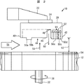
本発明の特徴を備えたディスク・ドライブの実施例10の構成図が図1に示されている。ディスク・ドライブ10は磁気円板媒体12を用いた回転ディスク・ドライブ型である。ディスク・ドライブ10の記憶容量は磁気記録媒体ディスク12の記録データの面密度である程度決定される。
A block diagram of a tenth embodiment of the disk drive having the features of the present invention is shown in FIG. The
ディスク・ドライブ10はディスク・ドライブ10の他の部品が組みつけられるハウジング14を有している。ハウジング14は底部16、側壁18及び上部(図示せず)を有しても良い。空気べアリング面44(図2、4及び5参照)を有し、近接するアクチュエータ22の端部にジンバル24を用いて取り付けられているスライダー20内に読み出し/書き込みヘッド52(図2参照)が配置されている。アクチュエータ22はモーター30のボイスコイル28の動作によりピボット点26を中心に回転し読み出し/書き込みヘッド52をディスク12の所定のトラックに位置づける。
The
スライダー20内の読み出し/書き込みヘッド52は、回転スピンドル32に搭載され、モーター(図示せず)で駆動されるディスク12と情報のやりとりを行う。アクチュエータ22はディスク12上でサスペンションに負荷あるいはバイアスを与え、読み出し/書き込みヘッド52をディスク12上に位置づけする。スライダー20内の読み出し/書き込みヘッド52は技術に通じた人には良く知られている電子回路によりディスク12にデータを書き込み読み出しを行うことが出来る。ディスク・ドライブ10内の様々な部品との電気接続はコネクタ34とケーブル36を通して行う。
A read / write
図1に示すディスク12とスライダー20の境界の機能側面図を図2に示す。(図2では寸法は無視されていることに注意)図2のディスク・ドライブ10はドライブが動作中の構成を示しており、ディスク12は参照番号38に示す方向に回転していて、スライダー20は、空気べアリング面44とディスク12の表面との相互作用により形成された空気べアリングにより、物理的にディスク12の表面から離れた位置にある。
A functional side view of the boundary between the
スライダー20は多相物質により作成してもよい。多相物質とは1つ以上の部品あるいは材料の相が存在することを意味する。1つの好適な多相物質はセラミック・アルミナ・チタンカーバイド(Al2O3―TiC)である。スライダー20はまたNi-Fe,Mn-Zn,及びNi-Znあるいはカルシウム・チタン石で作成することもできる。空気べアリング面44はAl2O3−TiO2及びZrO2などの硬質物質をプラズマ塗布で被覆しても良い。絶縁およびギャップ材はSiO2, SiO及びAl2O3で作成しても良い。他の好適な材料と製造工程は、迅速な公開のメリットを有する技術分野の通常の知識を有するものには明らかである。
The
スライダー20は前端40と後端42を有している。前端40と後端42の中間は下面すなわち空気べアリング面44である。空気べアリング面44はレール46、くぼみ部48、およびパッド50a−eを有している。後端42とパッド50c−eの近傍には読み出し/書き込みヘッド52がある。ある実施例ではディスクが回転していないときパッド50a−eがスライダー20をディスク12上に支持する設計になっている。これらの実施例ではディスク12とパッド50a−eの摩擦を減らすためディスク12は54に示す潤滑剤を有しても良い。他の例ではディスク上に静止することはないロード/アンロードスライダーが使用される場合もある。
The
動作中、図に示すようにディスク12の回転38により、レール46との間に矢印56で示すように空気が引き込まれ、圧力増大が生じ、スライダー20の空気べアリング面44が上方に押し上げられ、参照番号58で示すように読み出し/書き込みヘッド52がディスク12から引き離される。同時にくぼみ部48を通過する空気56は参照番号60に示すように圧力減少をもたらし、レール46に働く圧力作用にある程度の反作用を及ぼす。これらの圧力58,60ならびにアクチュエータ22から作用するバイアスの結果としてスライダー20はディスク28上に所期の浮上高さ62にて浮上する。
During operation, the
浮上高さ62を小さくしディスク12の高記録面密度を達成するため、レール46、くぼみ部48及びパッド50a−eの寸法を圧力58と60が等しくなるように調整した場合、スライダー20とディスク12の引きつけあう力が発生しスライダー20の空気べアリング面44で生成する圧力58と60のバランスが崩れ、空気べアリングの破壊、すなわちスライダー20とディスク12の接触に至る場合があることが見出された。主な力の2つはファン・デル・ワールズ力と静電気力である。これらの力は約5ナノメータ以下で急激に増大し、引きつけ力が圧力58より急激に増大するので空気べアリングが約2ナノメータ以下に崩落する場合がある。
In order to reduce the
ファン・デル・ワールズ力は電気的に中性な分子間に働く力である。静電気力は正または負に帯電した分子間に働く力である。本発明はスライダー20とディスク12に作用するファン・デル・ワールズ力と静電気力を少なくとも1つの空洞をスライダー20内に形成して減少させようとするものである。理論的にはスライダー20からどのような物質を取り除いてもスライダー20をディスク12に引き付けるファン・デル・ワールズ力と静電気力の効果が減少する。
Van der Waals forces are forces that act between electrically neutral molecules. The electrostatic force is a force acting between positively or negatively charged molecules. The present invention seeks to reduce Van der Waals forces and electrostatic forces acting on the
しかしながら、スライダー20の外面すなわち空気べアリング面44から物質を取り除くと空気べアリングの性能に影響する可能性がある。さらに、空気べアリングの外面から物質を取り除くと、ポケットその他の構造を生じ、破片、例えば塵埃、潤滑剤54、磁性体などが集まり、その結果エッチング深さが減少し外力が増加する可能性が生じ、最後には空気べアリングの破壊につながる。これらの破片は読み書きのギャップに侵入しヘッドとディスクとの間に望ましくない相互作用を引き起こす場合もある。さらにある種の構造を形成して、落下した破片がディスクに付着する場所に破片が集積して集まる場合がある。破片のかけらがディスクに付着すると、次の回転のときに破片のかけらがスライダーと衝突することがある。この衝突が起こるとスライダーの浮上高さが変動し、すなわち振動しディスクの読み出し書き込みが損なわれる。
However, removing material from the outer surface of the
単一の大きな空洞を形成するのはある種の環境で問題を起こす可能性がある。例えば、単一の大きな空洞が形成され破片が集積してエッチング深さが減少すると、浮上高さを減少させる可能性が高い。しかしながら、破片が集まらない対策を講ずれば、単一の大きな空洞を形成することにより、スライダーをディスクに引き付けるファン・デル・ワールズ力と静電気力を大幅に減少できる。 Forming a single large cavity can cause problems in certain environments. For example, if a single large cavity is formed and debris accumulate and the etch depth decreases, the flying height is likely to decrease. However, if measures are taken to prevent collection of debris, the formation of a single large cavity can greatly reduce Van der Waals and electrostatic forces that attract the slider to the disk.
従って、前述の観点より、複数の空洞をスライダーに形成し、スライダーとディスクとの間のファン・デル・ワールズ力と静電気力を依然として減少させつつどれかの空洞に破片が集積し空気べアリング性能に顕著な影響を及ぼす可能性を減少させるのが有利である。以下に説明される実施例は複数の内側空洞を有して示されているが、単一の内側空洞のスライダーも本発明の範囲であることは容易に理解されるところである。 Therefore, from the above viewpoint, a plurality of cavities are formed in the slider, and the van der Waals force and electrostatic force between the slider and the disk are still reduced, and debris accumulates in one of the cavities and air bearing performance It is advantageous to reduce the possibility of significant effects on Although the embodiments described below are shown with multiple inner cavities, it will be readily appreciated that a single inner cavity slider is also within the scope of the present invention.
かくして、図2に示す実施例では複数の菱形の柱状空洞64がスライダー20の後端のパッド50eに形成されメリットを生じている。複数の空洞をスライダー内に形成すると、空気べアリング性能には殆ど影響せず、空洞64は浮上高さ特性を殆ど変化させないので、空気べアリングはほぼ空洞64が存在しないかのように動作する。さらに、スライダー20は複数の空洞64を有することにより、破片の集まりやすさも減少している。
Thus, in the embodiment shown in FIG. 2, a plurality of rhomboid
図3に1つ以上の内側空洞と空気べアリング面を有するスライダーをエッチング形成する工程のフローチャートが示されている。“ブランク”のスライダーすなわち空気べアリング面のないスライダーが形成の始点となる。ブランク・スライダーは磁性ギャップなどの読み出し/書き込みヘッドの部分をしばしば有している。ブランク・スライダーの選択過程でスライダー材質が選定される。ブランク・スライダーはステップ90で選択される。
FIG. 3 shows a flowchart of a process for etching a slider having one or more inner cavities and an air bearing surface. A “blank” slider, ie a slider without an air bearing surface, is the starting point of formation. Blank sliders often have a read / write head portion such as a magnetic gap. The slider material is selected in the blank slider selection process. A blank slider is selected at
ブランク・スライダーから空気べアリング面と内側空洞を形成するため物質を取り除くのにエッチング処理がしばしば使用される。物質を取り除く処理であるエッチング処理は通常、すでにスライダーに形成済みの磁気ギャップを出来る限りディスク表面に近い位置を保ちたいが故に使用される。本技術に習熟した人には反応イオンエッチング(RIE)及び/またはイオンミリング処理が空気べアリング面と空洞を形成するのに使用できることはすぐに理解される。 An etching process is often used to remove material from the blank slider to form an air bearing surface and an inner cavity. An etching process, which is a process for removing material, is usually used because it is desired to keep the magnetic gap already formed on the slider as close to the disk surface as possible. Those skilled in the art will readily appreciate that reactive ion etching (RIE) and / or ion milling processes can be used to form air bearing surfaces and cavities.
ステップ92に空気べアリング面及び/または空洞を形成するためにスライダーにフォトレジストを適用することが示されている。次にステップ94でオーバレイ・マスクが適用される。ステップ96でスライダーは紫外線(UV)光に所期の時間さらされる。ステップ98でスライダーのエッチング処理が示される。最後にステップ100でフォトレジストの除去が示される。
かくして、図3に示されるようにスライダーに内側空洞を形成するのにはスライダー製造工程において1つ以上のマスキング工程を必要とする。さらに、エッチング処理は、時間を増大させた深エッチング処理及びスライダーに塗布されたフォトレジストへの紫外線照射中における、くぼみ部48などのくぼみ部の形成にも使用される。技術に習熟した人には他の処理も可能であることが理解される。
Thus, one or more masking steps are required in the slider manufacturing process to form the inner cavity in the slider as shown in FIG. Furthermore, the etching process is also used for the formation of indentations such as the
図3に示すステップにより形成され、図2に示したスライダー20の空気べアリング面44のワイヤフレーム透視図を図4に示す。スライダー20を形成する物質は透明であるとして示され、図の線は空気べアリング面の構造の縁を示し、さらに発明の特徴を示している。参照番号52'は図2に示す読み出し/書き込みヘッド52のおおよそのギャップ位置を示す。
A wire frame perspective view of the
本発明は、参照番号64で示すように後端のパッド50eにエッチング処理を施しパッド50eの内側に空洞を形成することにより、スライダー20とディスク12との間に作用する引き付け力を削減する。形成された空洞64は菱形の柱状の形状をしている。
The present invention reduces the attractive force acting between the
図5に図1−図2及び図4に示したスライダー20の空気べアリング面44の平面図を示す。スライダー20を構成する物質は透明であるとして示され、さらには発明の特徴を示している。図4には後端のパッド50eに形成された菱形形状の空洞64がより完全に示されている。パッド50eは本実施例ではディスク12に最も近いパッド50eとして選択され、ファン・デル・ワールズ力と静電気力を減少するのに顕著な効果がある。本技術分野に精通した人には空洞64の形状はスライダー20の製造工程にマスキング工程を追加すれば形成できることが容易に理解される。
FIG. 5 shows a plan view of the
スライダー20の、パッド50a−dなど他の部位にも空洞を形成してさらにスライダー20をディスク12に引き付ける力を減少しても良いことが、本技術分野に精通した人には容易に理解される。空洞はまたレール46に形成しても良い。従って、本発明は空洞の形成を後端パッド50eに限定するものではなく、スライダーをディスクに引き付ける力を減少させるためにスライダーに空洞を形成すること全体に適用される。
It will be readily appreciated by those skilled in the art that cavities may be formed in other parts of the
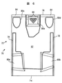
図6は本発明による他のスライダー72の空気べアリング面70の平面図を示す。スライダー72は前端74と後端76を有している。空気べアリング面70はレールとパッド78、80a−eを有している。前端と後端74、76の間とレールとパッド78、80a−eの間はくぼみ部82である。スライダー72は読み出し/書き込みヘッド(図示せず)に付随した読み出し/書き込みギャップ84を有している。
FIG. 6 shows a plan view of an
スライダー72はパッド84eに山形断面の柱形状86が形成され、スライダー72とディスク間の引き付け力、例えばファン・デル・ワールズ力および静電気力が減少している。空洞をパッド80a−d及び/あるいはレール78に形成してファン・デル・ワールズ力及び静電気力をさらに減少させることができることは本技術分野に精通した人には容易に理解される。実際には2次元あるいは3次元に形成されたどのようなパターンの空洞も使用することができる。さらに、付加する、及び/あるいは削除する処理を含めて空洞を形成するどのような方式も使用することができる。
In the slider 72, a
以上により、スライダーの安定浮上特性あるいは空気べアリング性能に殆ど影響することなく、ファン・デル・ワールズ力と静電気力の影響を減らした空気べアリング面を有し、低浮上高さで動作するスライダーが提供された。 As described above, the slider has an air bearing surface with reduced influence of van der Waals force and electrostatic force, and operates at a low flying height without affecting the stable flying characteristics or air bearing performance of the slider. Was provided.
上記実施例の説明により発明を説明し、また実施例はかなり詳細に説明したが、特許請求の範囲をこれらの詳細事項に限定するのを出願人が意図しているわけではない。技術に精通している人であれば、さらなる利点や変更を直ちに思いつくことができる。本発明の原理は存在するどのような空気べアリング設計にも実際に適用でき、浮上高さ特性には一般にほとんど影響しない、すなわち設計変更を通常必要としないということが理解される。本発明はその幅広い意味において、特定の詳細、特定の装置、方法、示され説明されたサンプルに限定されるものではない。従って出願人の発明の概念の精神と範囲を外れることなくこれら詳細から変更を行うことができる。 Although the invention has been described in the foregoing description of the embodiments, and the embodiments have been described in considerable detail, it is not intended by the applicant to limit the scope of the claims to these details. Anyone familiar with the technology can immediately come up with further benefits and changes. It will be appreciated that the principles of the present invention are practically applicable to any existing air bearing design and generally have little effect on flying height characteristics, i.e. usually require no design changes. The invention in its broadest sense is not limited to the specific details, specific apparatus, methods, or samples shown and described. Accordingly, changes may be made from these details without departing from the spirit or scope of applicant's inventive concept.
10…ディスク・ドライブ、12…磁気ディスク、20,72…スライダー、22…アクチュエータ、24…ジンバル、32…回転スピンドル、40.74…前端、42,76…後端、44,70…空気ベアリング、46,78…レール、48,82…くぼみ部、
50a,50b,50c,50d,50e…パッド、
80a,80b,80c,80d,80e…パッド、
52…読み出し/書き込みヘッド、62…浮上高さ、64、86…空洞、84…読み出し/書き込みギャップ。
DESCRIPTION OF
50a, 50b, 50c, 50d, 50e ... pad,
80a, 80b, 80c, 80d, 80e ... pad,
52 ... Read / write head, 62 ... Flying height, 64, 86 ... Cavity, 84 ... Read / write gap.
Claims (11)
前記ディスクの面に沿って伸びるアクチュエータと、
前記アクチュエータの端部近傍に取り付けられたスライダーと、を有するディスク・ドライブにおいて、
前記スライダーは前記ディスク面に向かい合った空気ベアリング面を有し、前記空気ベアリング面は、前端側のパッドと、後端側中央部のヘッドが配置されたパッドと、これらのパッドに囲まれたくぼみ部とを有し、前記後端側中央部のパッドは前記ディスクに引きつけるファンデルワールズ力と静電気力を減少する複数の柱状に形成された空洞を有するディスク・ドライブ。 A rotatable disc having a recordable medium;
An actuator extending along the surface of the disk;
In a disk drive having a slider attached near the end of the actuator ,
The slider has an air bearing surface facing the disk surface, and the air bearing surface includes a front end pad, a pad on which a rear end side central portion is disposed, and a recess surrounded by these pads. and a section, the pad of the rear-side central portion a disk drive having a cavity formed in a plurality of columnar reducing the van der Waals force and electrostatic force to attract the disc.
前記空気ベアリング面は、前端側のパッドと、後端側中央部のヘッドが配置されたパッドと、これらのパッドに囲まれたくぼみ部とを有し、前記後端側中央部のパッドは前記ディスクに引きつけるファンデルワールズ力と静電気力を減少する複数の柱状に形成された空洞を有するスライダー。 The air bearing surface includes a front end side pad, a pad on which a rear end side central portion head is disposed, and a recessed portion surrounded by these pads. A slider having a plurality of columnar cavities that reduce van der Waals and electrostatic forces attracting the disk.
前記スライダーの後端側パッドに、スライダーの安定浮上特性に殆ど影響することなくディスク面に引きつけるファンデルワールズ力と静電気力とを減少する複数の柱状の空洞をエッチングにより形成するステップと、を含むスライダーの製造方法。 Forming a plurality of columnar cavities on the rear end pad of the slider by etching to reduce van der Waals force and electrostatic force attracting the disk surface with little influence on the stable flying characteristics of the slider. Manufacturing method of slider.
Applications Claiming Priority (1)
| Application Number | Priority Date | Filing Date | Title |
|---|---|---|---|
| US10/242,058 US7023664B2 (en) | 2002-09-12 | 2002-09-12 | Air bearing designs to reduce external van der waals and electrostatic forces |
Publications (3)
| Publication Number | Publication Date |
|---|---|
| JP2004103221A JP2004103221A (en) | 2004-04-02 |
| JP2004103221A5 JP2004103221A5 (en) | 2006-10-12 |
| JP4192059B2 true JP4192059B2 (en) | 2008-12-03 |
Family
ID=31991315
Family Applications (1)
| Application Number | Title | Priority Date | Filing Date |
|---|---|---|---|
| JP2003309564A Expired - Fee Related JP4192059B2 (en) | 2002-09-12 | 2003-09-02 | Air bearing design to reduce van der Waals and electrostatic forces acting from the outside |
Country Status (4)
| Country | Link |
|---|---|
| US (1) | US7023664B2 (en) |
| JP (1) | JP4192059B2 (en) |
| CN (1) | CN100389457C (en) |
| SG (1) | SG121793A1 (en) |
Families Citing this family (14)
| Publication number | Priority date | Publication date | Assignee | Title |
|---|---|---|---|---|
| JP2005182883A (en) * | 2003-12-17 | 2005-07-07 | Fujitsu Ltd | Head slider and magnetic storage apparatus |
| JP2006120228A (en) * | 2004-10-20 | 2006-05-11 | Toshiba Corp | Disk apparatus |
| US7259931B2 (en) * | 2005-04-18 | 2007-08-21 | Matsushita Electrical Industrial Co., Ltd. | Slider design for high fly write immunity |
| US20070025023A1 (en) * | 2005-07-26 | 2007-02-01 | Hitachi Global Storage Technologies Netherlands B.V. | Magnetic head slider with suppressed flying height reduction and magnetic hard disk drive |
| JP4981286B2 (en) * | 2005-09-14 | 2012-07-18 | ヒタチグローバルストレージテクノロジーズネザーランドビーブイ | Magnetic disk drive and magnetic head slider |
| US7903375B2 (en) * | 2006-04-11 | 2011-03-08 | Hitachi Global Storage Technologies, Netherlands, B.V. | Proximity recording slider with high air bearing damping in and out of contact |
| JP2009015891A (en) * | 2007-06-29 | 2009-01-22 | Toshiba Corp | Head, head suspension assembly, and disk device equipped with the same |
| US7586711B2 (en) * | 2007-12-10 | 2009-09-08 | Hitachi Global Storage Technologies Netherlands B.V. | Magnetic performance of a magnetic transducer operating within a hard disk drive |
| US8174794B2 (en) * | 2008-11-26 | 2012-05-08 | Hitachi Global Storage Technologies, Netherlands B.V. | Slider having a lubricant-accumulation barrier including a plurality of lubricant-accumulation-barrier portions |
| US8169744B2 (en) * | 2008-11-26 | 2012-05-01 | Hitachi Global Storage Technologies, Netherlands B.V. | Slider having a lubricant-accumulation barrier |
| US20110007423A1 (en) * | 2009-07-13 | 2011-01-13 | Seagate Technology Llc | Supplemental Layer to Reduce Damage from Recording Head to Recording Media Contact |
| CN107123977B (en) | 2016-02-24 | 2019-04-19 | 比亚迪股份有限公司 | The driving circuit of transistor |
| US9940960B2 (en) * | 2016-05-24 | 2018-04-10 | Sae Magnetics (Hk) Ltd. | Air-bearing design for hydrocarbon and lube pick-up improvements in hard disk drive (HDD) |
| US11587584B1 (en) * | 2022-02-28 | 2023-02-21 | Western Digital Technologies, Inc. | Slider air bearing design with ultra-low pressure for low power-consumption data storage devices |
Family Cites Families (13)
| Publication number | Priority date | Publication date | Assignee | Title |
|---|---|---|---|---|
| US4644641A (en) * | 1985-12-30 | 1987-02-24 | Memorex Corporation | Fabrication of "Delta" magnetic head-sliders |
| US5079657A (en) * | 1990-02-15 | 1992-01-07 | Applied Magnetics Corporation | Textured air bearing surface |
| US5742518A (en) * | 1995-07-28 | 1998-04-21 | Seagate Technology, Inc. | Stiction model for a head-disc interface of a rigid disc drive |
| US5940249A (en) * | 1997-11-10 | 1999-08-17 | International Business Machines Corporation | Shielded air bearing slider |
| US6233118B1 (en) * | 1997-12-04 | 2001-05-15 | Zine-Eddine Boutaghou | System for capturing wear debris in a data storage system |
| US6366429B1 (en) | 1998-03-20 | 2002-04-02 | Seagate Technology Llc | Patterned and directional selective roughening of a slider air-bearing surface |
| US6381090B1 (en) | 1998-05-21 | 2002-04-30 | Komag, Incorporated | Hard disk drive head-media system having reduced stiction and low fly height |
| US6466410B2 (en) * | 1998-10-13 | 2002-10-15 | Seagate Technology Llc | Slider for a data storage device with head disc interface for contact starts and stops (“CSS”) |
| US6504682B1 (en) * | 1999-12-02 | 2003-01-07 | Seagate Technology Llc | Disc head slider having recessed, channeled rails for reduced stiction |
| US6490134B2 (en) * | 2000-01-11 | 2002-12-03 | Seagate Technology Llc | Patterned and directional selective roughening of a slider air-bearing surface |
| US6510027B1 (en) * | 2000-02-11 | 2003-01-21 | Seagate Technology Llc | Disc head slider having highly damped bearing with multiple pressure gradiant-generating pads |
| US6710976B2 (en) * | 2000-10-04 | 2004-03-23 | Seagate Technology Llc | Disk head slider having air bearing pressure relief features |
| US6697223B2 (en) * | 2000-12-11 | 2004-02-24 | Seagate Technology Llc | Disc head slider with pole tip spacing de-coupled from slider fly height |
-
2002
- 2002-09-12 US US10/242,058 patent/US7023664B2/en not_active Expired - Fee Related
-
2003
- 2003-09-02 JP JP2003309564A patent/JP4192059B2/en not_active Expired - Fee Related
- 2003-09-08 SG SG200305359A patent/SG121793A1/en unknown
- 2003-09-12 CN CNB031581536A patent/CN100389457C/en not_active Expired - Fee Related
Also Published As
| Publication number | Publication date |
|---|---|
| US20040052001A1 (en) | 2004-03-18 |
| JP2004103221A (en) | 2004-04-02 |
| CN1505004A (en) | 2004-06-16 |
| US7023664B2 (en) | 2006-04-04 |
| CN100389457C (en) | 2008-05-21 |
| SG121793A1 (en) | 2006-05-26 |
Similar Documents
| Publication | Publication Date | Title |
|---|---|---|
| JP4192059B2 (en) | Air bearing design to reduce van der Waals and electrostatic forces acting from the outside | |
| US7916426B2 (en) | Head with an air bearing surface having left and right leading pressurizing steps, each with short and long regions | |
| US6771468B1 (en) | Slider with high pitch-stiffness air bearing design | |
| US5793568A (en) | Air bearing slider deflection apparatus and method for fabricating same | |
| US6396664B2 (en) | Negative pressure air bearing slider | |
| US6937439B1 (en) | Slider having a textured air bearing surface, head stack assembly and disk drive using same | |
| US7760468B2 (en) | Air-bearing design with particle rejection features | |
| JP2001344724A (en) | Floating head slider | |
| JP2007220232A (en) | Head device and disk device having the same | |
| JP5060634B1 (en) | Head, head gimbal assembly including the head, and disk device | |
| KR20030091958A (en) | Air bearing slider | |
| US6674611B2 (en) | Air bearing design producing steeper ramp profile near the laser texture zone | |
| EP1447796B1 (en) | Air bearing slider for disk drive | |
| WO2003069619A1 (en) | Ramp load device, and disk device using the device | |
| JP2005302262A (en) | Slider for high-density magnetic recording, disk drive, and method for manufacturing the slider | |
| US7110220B2 (en) | Head slider having pads formed on rail surfaces | |
| JPH09265750A (en) | Slider and its formation and system therefor | |
| US7324306B2 (en) | System, method, and apparatus for improving the multiple velocity performance and write element protrusion compensation of disk drive sliders | |
| US7929249B2 (en) | Spring loaded head for reduced fly height and tracking control | |
| JP2003091953A (en) | Slider assembly | |
| KR100450673B1 (en) | Removing method of contaminent on a disk, housing and disk assembly of hard disk drive adopting the method | |
| JP4198557B2 (en) | Head slider and magnetic disk apparatus having the head slider | |
| US7813080B2 (en) | Enhanced planarization liftoff structure and method for making the same | |
| KR100440790B1 (en) | Head slider device of hard disk drive, particularly for pcr(pseude contact recording) between head slider and media | |
| KR100392670B1 (en) | Head device of hard disk drive |
Legal Events
| Date | Code | Title | Description |
|---|---|---|---|
| A521 | Request for written amendment filed |
Free format text: JAPANESE INTERMEDIATE CODE: A523 Effective date: 20060829 |
|
| A621 | Written request for application examination |
Free format text: JAPANESE INTERMEDIATE CODE: A621 Effective date: 20060829 |
|
| RD02 | Notification of acceptance of power of attorney |
Free format text: JAPANESE INTERMEDIATE CODE: A7422 Effective date: 20060829 |
|
| A977 | Report on retrieval |
Free format text: JAPANESE INTERMEDIATE CODE: A971007 Effective date: 20080225 |
|
| A131 | Notification of reasons for refusal |
Free format text: JAPANESE INTERMEDIATE CODE: A131 Effective date: 20080415 |
|
| A521 | Request for written amendment filed |
Free format text: JAPANESE INTERMEDIATE CODE: A523 Effective date: 20080626 |
|
| TRDD | Decision of grant or rejection written | ||
| A01 | Written decision to grant a patent or to grant a registration (utility model) |
Free format text: JAPANESE INTERMEDIATE CODE: A01 Effective date: 20080826 |
|
| A01 | Written decision to grant a patent or to grant a registration (utility model) |
Free format text: JAPANESE INTERMEDIATE CODE: A01 |
|
| A61 | First payment of annual fees (during grant procedure) |
Free format text: JAPANESE INTERMEDIATE CODE: A61 Effective date: 20080919 |
|
| FPAY | Renewal fee payment (event date is renewal date of database) |
Free format text: PAYMENT UNTIL: 20110926 Year of fee payment: 3 |
|
| R150 | Certificate of patent or registration of utility model |
Free format text: JAPANESE INTERMEDIATE CODE: R150 |
|
| FPAY | Renewal fee payment (event date is renewal date of database) |
Free format text: PAYMENT UNTIL: 20120926 Year of fee payment: 4 |
|
| FPAY | Renewal fee payment (event date is renewal date of database) |
Free format text: PAYMENT UNTIL: 20120926 Year of fee payment: 4 |
|
| S533 | Written request for registration of change of name |
Free format text: JAPANESE INTERMEDIATE CODE: R313533 |
|
| FPAY | Renewal fee payment (event date is renewal date of database) |
Free format text: PAYMENT UNTIL: 20120926 Year of fee payment: 4 |
|
| R350 | Written notification of registration of transfer |
Free format text: JAPANESE INTERMEDIATE CODE: R350 |
|
| FPAY | Renewal fee payment (event date is renewal date of database) |
Free format text: PAYMENT UNTIL: 20130926 Year of fee payment: 5 |
|
| R250 | Receipt of annual fees |
Free format text: JAPANESE INTERMEDIATE CODE: R250 |
|
| R250 | Receipt of annual fees |
Free format text: JAPANESE INTERMEDIATE CODE: R250 |
|
| LAPS | Cancellation because of no payment of annual fees |