JP4189964B2 - Sound ejection of fluid using a large F-number focusing element - Google Patents
Sound ejection of fluid using a large F-number focusing element Download PDFInfo
- Publication number
- JP4189964B2 JP4189964B2 JP2003526688A JP2003526688A JP4189964B2 JP 4189964 B2 JP4189964 B2 JP 4189964B2 JP 2003526688 A JP2003526688 A JP 2003526688A JP 2003526688 A JP2003526688 A JP 2003526688A JP 4189964 B2 JP4189964 B2 JP 4189964B2
- Authority
- JP
- Japan
- Prior art keywords
- fluid
- reservoir
- ejector
- droplet
- sonic
- Prior art date
- Legal status (The legal status is an assumption and is not a legal conclusion. Google has not performed a legal analysis and makes no representation as to the accuracy of the status listed.)
- Expired - Lifetime
Links
Images


Classifications
-
- B—PERFORMING OPERATIONS; TRANSPORTING
- B41—PRINTING; LINING MACHINES; TYPEWRITERS; STAMPS
- B41J—TYPEWRITERS; SELECTIVE PRINTING MECHANISMS, i.e. MECHANISMS PRINTING OTHERWISE THAN FROM A FORME; CORRECTION OF TYPOGRAPHICAL ERRORS
- B41J2/00—Typewriters or selective printing mechanisms characterised by the printing or marking process for which they are designed
- B41J2/005—Typewriters or selective printing mechanisms characterised by the printing or marking process for which they are designed characterised by bringing liquid or particles selectively into contact with a printing material
- B41J2/01—Ink jet
- B41J2/135—Nozzles
- B41J2/14—Structure thereof only for on-demand ink jet heads
- B41J2/14008—Structure of acoustic ink jet print heads
Description
本発明は、流体の射出における集束された音波エネルギーの使用に一般的に関し、より具体的には、大きいF番号集束要素を使用する液滴の音波射出に関する。 The present invention relates generally to the use of focused sonic energy in fluid ejection, and more specifically to sonic ejection of droplets using large F-number focusing elements.
多くの特許は、液滴射出における音波エネルギーの使用を記載している。例えば、Loveladyらに対する米国特許第4,308,547号は、文書上に文字またはバーコードを形成するための、液体の本体から、移動する文書上への液体の排出において音波原理を利用する液滴エミッターを記載する。Loveladyらは、ノズルレスインクジェット印刷機に関し、ここで、制御されたインクの液滴は、そのインクの表面またはその表面より下にある曲線状の変換器によって作成される音波力によって発射される。 Many patents describe the use of sonic energy in droplet ejection. For example, US Pat. No. 4,308,547 to Lovelady et al. Describes a liquid that utilizes the sonic principle in discharging liquid from a body of liquid onto a moving document to form characters or barcodes on the document. A drop emitter is described. Lovelessy et al. Relates to a nozzleless ink jet printer, where a controlled drop of ink is fired by sonic forces created by the surface of the ink or a curved transducer below the surface.
このLoveladyらの特許は、音波エネルギーを発生および集束するための圧電シェル変換器を使用する。いくつかの他の方法もまた、発生した音波エネルギーの集束および液滴の射出のために開発されている。例えば、音波的に照射された球状音波集束レンズは、Elrodらに対する米国特許第4,751,529号に記載されるとおりであり、そしてインターディジタル電極を備える平面圧電変換器は、Quateらに対する米国特許第4,697,105号に記載されるとおりである。現在の液滴イジェクター技術は、ラスター出力スキャナ(ROS)のための比較的単純な単一のイジェクター実施形態からより複雑な実施形態にわたる種々のプリントヘッド配置(例えば、行印字のための1次元または2次元のフルページ幅のアレイの液滴イジェクター)を設計するのに使用されている。同時継続中の譲渡され公開された米国特許出願番号:US2002/0037579「Acoustic Ejection of Fluids from a Plurality of Reservoirs」(2002年3月28日公開);US2002/0061258「Focused Acoustic Energy in the Preparation and Screening of Combinatorial Libraries」(2002年5月23日公開);およびUS2002/0042077「Arrays of Partially Nonhybridizing Oligonucleotides and Preparation Thereof Using Focused Acoustic Energy」(2002年4月11日公開)に記載されるような、生物学的材料のアレイの合成における使用もまた、見出される。 The Lovelady et al. Patent uses a piezoelectric shell transducer to generate and focus sonic energy. Several other methods have also been developed for focusing the generated sonic energy and ejecting droplets. For example, a sonically irradiated spherical acoustic focusing lens is as described in US Pat. No. 4,751,529 to Elrod et al., And a planar piezoelectric transducer with interdigital electrodes is the US to Quate et al. As described in Japanese Patent No. 4,697,105. Current droplet ejector technology uses a variety of printhead arrangements ranging from relatively simple single ejector embodiments for raster output scanners (ROS) to more complex embodiments (eg, one-dimensional or It is used to design 2D full page width array droplet ejectors. US Patent Application No. US2002 / 0037579, “Continued and Published in March 28, 2002”; US2002 / 0061258, “Focused Acoustics in the United States” of Combined Libraries (published on May 23, 2002); and US 2002/0042077, “Arrays of Partially Non-oligolytics and Preparation Theoretics Focusing Us Energy "as described (published Apr. 11, 2002), use in the synthesis of an array of biological material are also found.
しかし、ノズルレス流体射出の開発は、一般的にはインク印刷用途に限定されており、そして約1のF番号を有する音波レンズにもっぱら頼っている。残念ながら、低いF番号のレンズは、レザバおよび流体レベル幾何学に制限を設け、比較的制限された深度の集束を提供し、そしてレザバ中の流体レベルに対する感度を増加させる。例えば、二分子アレイ用途において、このアレイを構築する種々の二分子材料から、ウエルプレート中の個々のウエル中に通常含まれる。これらのウエルは、しばしば、約5:1のアスペクト比(すなわち、そのウエルは、直径の5倍の深さである)を有する。このウエルの狭さは、F1レンズが使用される場合、レザバ内の流体の表面がそのレンズ開口部の幅よりもレンズから離れていないところにあることを必要とする。従って、5:1のアスペクト比のウエル中でF1レンズを使用する場合、レザバの低部から1/5のみが流体によって満たされ得る。 However, the development of nozzleless fluid ejection is generally limited to ink printing applications and relies solely on acoustic lenses having an F number of about 1. Unfortunately, low F number lenses place limits on the reservoir and fluid level geometry, provide relatively limited depth focusing, and increase sensitivity to fluid levels in the reservoir. For example, in bimolecular array applications, the various bimolecular materials that make up the array are usually included in individual wells in a well plate. These wells often have an aspect ratio of about 5: 1 (i.e., the well is 5 times deep in diameter). This narrowness of the well requires that when an F1 lens is used, the surface of the fluid in the reservoir is no further from the lens than the width of its lens opening. Thus, when using an F1 lens in a 5: 1 aspect ratio well, only 1/5 from the bottom of the reservoir can be filled with fluid.
従って、十分な液滴射出精度を有する音波流体射出デバイスおよび方法を改善し、その結果、低いF番号のレンズに関連する不利益を伴わずに、高密度分子配アレイの調製を可能にすることが、この分野において必要とされる。F2レンズの使用が、Elrodら(1989),「Nozzleless droplet formation with focused acoustic beams」J.Appl.Phys 65(9):3441−3447に示唆されているが、この参考文献は、このようなレンズが、液滴直径に関する予測不可能な結果および使用可能な集束深度を提供することを示す。驚いたことに、2よりも大きいF番号を有するレンズの使用が、非常に増大された集束深度を提供しつつ、液滴サイズおよび速度の非常に優れた制御を可能にするので、大きいF番号のレンズは、F1レンズに対してさらなる利点を提供することが現在、明らかとなってきている。 Accordingly, to improve sonic fluid ejection devices and methods with sufficient droplet ejection accuracy, thus enabling the preparation of high density molecular arrays without the disadvantages associated with low F number lenses Is needed in this area. The use of F2 lenses is described in Elrod et al. (1989), “Nozzleless droplet formation with focused acoustic beams” J. MoI. Appl. Although suggested in Phys 65 (9): 3441- 3447, this reference shows that such a lens provides unpredictable results for drop diameter and usable focus depth. Surprisingly, the use of a lens with an F number greater than 2 allows a very good control of droplet size and velocity while providing a greatly increased depth of focus, so a large F number. It is now clear that this lens offers additional advantages over the F1 lens.
従って、本発明の目的は、上述の先行技術の欠点を克服するデバイスおよび方法を提供することである。 Accordingly, it is an object of the present invention to provide devices and methods that overcome the above-mentioned drawbacks of the prior art.
本発明の1つの局面において、デバイスは、複数の流体液滴を基材表面上の設定された部位に音波的に射出するために提供され、以下を備える:流体を収容するように適合されたレザバであって、このレザバは、実質的に均一な様式で音波エネルギーの伝播を可能にする開口部を備え、このレザバの開口部は、有効寸法を有している;ならびに音波放射を発生させるための音波放射発生装置で構成されるイジェクターおよび発生した音波放射を集束して、流体レザバ内に含まれる流体表面から液滴を放射させ得る集束手段であって、この表面は、開口部から有効な距離にあり、ここで、開口部に対する有効距離 対 開口部の有効寸法の比は、約2:1よりも大きい。このデバイスは、レザバに対して音波カップリング関係でイジェクターを配置するための手段をさらに包含し得る。好ましくは、この比は、約3:1、またはより好ましくは、約4:1より大きい。このデバイスはまた、複数のレザバを備え、この各レザバは、流体を収容するように適合され、そして、ここで、このデバイスは、複数の各レザバから基材表面上の複数の設定された部位に対して液滴を射出し得る。 In one aspect of the invention, a device is provided for sonically ejecting a plurality of fluid droplets to a set site on a substrate surface, comprising: adapted to contain a fluid A reservoir comprising an opening that allows propagation of sonic energy in a substantially uniform manner, the reservoir opening having an effective dimension; and generating sonic radiation An ejector configured with a sound radiation generator for focusing and a focusing means capable of focusing the generated sound radiation to emit droplets from the fluid surface contained in the fluid reservoir, the surface being effective from the opening Where the ratio of the effective distance to the opening to the effective size of the opening is greater than about 2: 1. The device may further include means for positioning the ejector in a sonic coupling relationship with the reservoir. Preferably, this ratio is greater than about 3: 1, or more preferably greater than about 4: 1. The device also includes a plurality of reservoirs, each of which is adapted to contain a fluid, and wherein the device includes a plurality of set sites on the substrate surface from each of the plurality of reservoirs. Droplets can be ejected against
別の局面において、本発明は、流体レザバから基材表面上の設定された部位に対して流体を射出するための方法に関する。この方法は、第1の流体を収容するレザバ(このレザバは、実質的に均一な様式で音波エネルギーの伝播を可能にする開口部を有し、この開口部は、有効寸法を有している)で構成されるデバイスおよび音波放射を発生させるための音波放射発生装置で構成されるイジェクターおよび発生した音波放射を集束して流体レザバ内に収容される第1の流体の表面(この表面は、開口部からの有効距離にある)から液滴を放出させるための集束手段を提供する工程を包含し、ここで、開口部からの有効距離 対 開口部の有効直径の比は、約2:1より大きい。次いで、このイジェクターが流体含有レザバに対して音波的に結合された関係であるように配置され、その結果このイジェクターの位置は、第1の流体の表面近くの射出手段の焦点(すなわち、開口部からの有効距離)に配置される。最終的には、このイジェクターが起動され、それによって第1の流体表面に直径Dの焦点を有する音波放射を発生し、レザバからの第1の流体の液滴の射出を生じる。所望の場合、この方法は、複数の流体レザバによって反復され得、このレザバの各々は流体を収容し、そして各レザバは、一般的には(必須ではないが)異なる流体を収容する。従って、この音波イジェクターは、各レザバから基材表面上の異なる設定部位に対して液滴を射出するように繰り返し再配置される。このように、この方法は、基材表面上の分子部分の配列を作成するのに使用するために容易に適合される。 In another aspect, the present invention relates to a method for ejecting fluid from a fluid reservoir to a set site on a substrate surface. The method includes a reservoir containing a first fluid that has an opening that allows propagation of sonic energy in a substantially uniform manner, the opening having an effective dimension. ) And a first fluid surface that focuses the generated sound radiation and is contained in a fluid reservoir (this surface comprises: Providing a focusing means for ejecting droplets from (at an effective distance from the opening), wherein the ratio of effective distance from the opening to effective diameter of the opening is about 2: 1 Greater than. The ejector is then placed in a sonically coupled relationship to the fluid-containing reservoir so that the position of the ejector is the focal point of the ejection means near the surface of the first fluid (ie, the opening (Effective distance from). Eventually, the ejector is activated, thereby generating acoustic radiation having a diameter D focus on the first fluid surface, resulting in the ejection of the first fluid droplet from the reservoir. If desired, the method can be repeated with multiple fluid reservoirs, each of which contains a fluid, and each reservoir typically contains a different fluid (although not essential). Therefore, the sonic ejector is repeatedly rearranged so that droplets are ejected from each reservoir to different setting sites on the substrate surface. Thus, this method is easily adapted for use in creating an array of molecular moieties on a substrate surface.
(本発明を実施するための様式)
(定義および概要):
本発明を詳細に記載する前に、本発明は、特定の流体、生体分子またはデバイス構造に限定されず、変化し得ることが理解されるべきである。本明細書中で使用される用語は、特定の実施形態のみを記載する目的のためであって、限定するために意図されないこともまた、理解されるべきである。
(Mode for carrying out the present invention)
(Definition and summary):
Before describing the present invention in detail, it is to be understood that the present invention is not limited to a particular fluid, biomolecule or device structure and can vary. It is also to be understood that the terminology used herein is for the purpose of describing particular embodiments only and is not intended to be limiting.
本明細書中および添付の特許請求の範囲において使用される場合、「1つの(a)」「1つの(an)」「その(この)(the)」は、文脈がそうでないことを明確に示さない限り、複数形も含む。従って、例えば、「レザバ(a reservoir)」に対する言及は、複数のレザバを含み、「流体(a fluid)」に対する言及は、複数の流体を含み、「生体分子(a biomolecule)」に対する言及は、生体分子の組み合わせを含む、など。 As used herein and in the appended claims, “one (a)” “one (an)” “the (this)” clearly indicates that the context is not. Plural forms are also included unless otherwise indicated. Thus, for example, reference to “a reservoir” includes a plurality of reservoirs, reference to “a fluid” includes a plurality of fluids, and reference to “a biomolecule” is Including combinations of biomolecules, etc.
本発明の記載および特許請求の範囲において、以下の専門用語は、以下に示される定義に従って使用される。 In describing and claiming the present invention, the following terminology will be used in accordance with the definitions set out below.
本明細書中で使用される用語「音波カップリング」および「音波的にカップリングされる」は、物体が、別の物体と直接的または間接的に接触する位置に配置され、音波放射を、音波エネルギーの実質的な損失なしに、その物体間で伝播させるような状態のことをいう。2つのアイテムが間接的に音波的にカップリングされる場合、それを通って音波放射が伝播し得る中間体を提供するための「音波カップリング媒体」が必要とされる。従って、イジェクターは、(例えば、イジェクターを流体中に浸すかまたはイジェクターと流体との間に音波カップリング媒体を挿入することによって)流体に音波的に音波的に結合され得、その流体結合媒体を介するイジェクターによって発生された音波放射を流体中に伝播する。 As used herein, the terms “sonic coupling” and “sonically coupled” refer to an object placed at a position where it is in direct or indirect contact with another object, A state in which sound waves propagate between objects without substantial loss of energy. When two items are indirectly sonically coupled, a “sonic coupling medium” is required to provide an intermediate through which sonic radiation can propagate. Thus, an ejector can be sonically and acoustically coupled to a fluid (eg, by immersing the ejector in a fluid or by inserting a sonic coupling medium between the ejector and the fluid). Propagating sound wave radiation generated by the intervening ejector into the fluid.
本明細書中で使用される場合、用語「沈着」は、基材表面による分子の非共有的な保持のことをいう。すなわち、沈着は、沈着される分子上に存在する基材表面と沈着部分との間の非共有的な相互作用の結果として生じる。沈着は、水素結合、ファンデルワールス力、極性引力または静電力(すなわちイオン結合を介する)を介して生じ得る。沈着部分の例としては、以下が挙げられるが、これらに限定されない:アミン基、カルボン酸部分、ヒドロキシル基、ニトロソ基、スルホンなど。 As used herein, the term “deposition” refers to the non-covalent retention of molecules by a substrate surface. That is, deposition occurs as a result of non-covalent interactions between the substrate surface present on the deposited molecule and the deposited portion. Deposition can occur via hydrogen bonds, van der Waals forces, polar attractive forces or electrostatic forces (ie, via ionic bonds). Examples of deposition moieties include, but are not limited to: amine groups, carboxylic acid moieties, hydroxyl groups, nitroso groups, sulfones, and the like.
本明細書中で使用される用語「アレイ」は、レザバの配置(例えば、ウエルプレート中のウエル)または基材表面上の流体液滴または分子部分の配置(オリゴヌクレオチドアレイまたはペプチドアレイとして)のような特徴の二次元配置をいう。アレイは、一般的には、例えば、直線グリッド、並行ストライプなどのように規則的に順序付けられた特徴で構成されるが、順序付けられていないアレイも有利に使用され得る。アレイは、規則的かつ順序付けられた特徴を含む必要のないパターンとは異なる。本発明のデバイスおよび方法を使用して形成されるアレイもパターンも、人の肉眼に対する光学的な有意性を有さない。例えば、本発明は、人の肉眼に対して光学的な有意性を有する、文字、数字、バーコード、図、または他の銘を形成するための、紙または他の基材上へのインク印刷に関しない。さらに、本明細書中で提供されるような表面上に射出された液滴の沈着によって形成されるアレイおよびパターンは、好ましくは、人の肉眼に実質的に不可視である。アレイは、典型的には(しかし必要ではない)、少なくとも約4〜約10,000,000の特徴を含み、一般的には、約4〜約1,000,000特徴の範囲である。 As used herein, the term “array” refers to the arrangement of reservoirs (eg, wells in a well plate) or the arrangement of fluid droplets or molecular parts on a substrate surface (as an oligonucleotide array or peptide array). A two-dimensional arrangement of such features. An array is typically composed of regularly ordered features such as, for example, a linear grid, parallel stripes, etc., but unordered arrays may also be used advantageously. An array is different from a pattern that does not need to include regular and ordered features. Neither arrays nor patterns formed using the devices and methods of the present invention have optical significance to the human eye. For example, the present invention provides ink printing on paper or other substrates to form letters, numbers, barcodes, diagrams, or other inscriptions that are optically significant to the human eye. Not related. Furthermore, the arrays and patterns formed by the deposition of ejected droplets on a surface as provided herein are preferably substantially invisible to the human eye. Arrays typically (but need not) include at least about 4 to about 10,000,000 features, and generally range from about 4 to about 1,000,000 features.
用語「結合された(attached)」は、例えば、基材表面が基材表面に「結合した」分子部分を有する場合、(例えば、本発明の方法論を使用して作成されるアレイ中の個々の分子部分において)共有結合、沈着、および物理的な固定化を含む。用語「結合(binding)」および「結合(bound)」は、用語「結合(attached)」の意味と同一である。 The term “attached” refers to, for example, an individual in an array made using the methodology of the present invention (eg, where the substrate surface has molecular moieties “bound” to the substrate surface). Includes covalent bonding, deposition, and physical immobilization (in the molecular part). The terms “binding” and “bound” have the same meaning as the term “attached”.
用語「生体分子」は、本明細書中で使用される場合、全体または一部が、天然に存在し得るか、組換え的に産生されるかまたは化学的に合成されるかに関わらず、任意の有機分子をいう。すなわち、生体分子は、生存生物の一部であったかまたは生存生物の一部であり得る。この用語は、例えば、ヌクレオチド、アミノ酸および単糖類、ならびにオリゴヌクレオチドおよびポリヌクレオチドのようなオリゴマー種およびポリマー種、オリゴペプチド、ポリペプチドおよびタンパク質のようなペプチド分子、ならびに二糖類、オリゴ糖、多糖類のような糖類などを包含する。 The term “biomolecule” as used herein, whether in whole or in part, may be naturally occurring, recombinantly produced or chemically synthesized. Any organic molecule. That is, the biomolecule was part of a living organism or can be part of a living organism. The term includes, for example, nucleotides, amino acids and monosaccharides, and oligomeric and polymeric species such as oligonucleotides and polynucleotides, peptide molecules such as oligopeptides, polypeptides and proteins, and disaccharides, oligosaccharides, polysaccharides Saccharides such as
本明細書中で使用される場合、用語「ヌクレオシド」および「ヌクレオチド」は、従来のプリンおよびピリミジン塩基(すなわち、アデニン(A)、チミン(T)、シトシン(C)、グアニン(G)およびウラシル(U)のみではなく、その保護形態(例えば、この塩基は、アセチル、ジフルオロアセチル、トリフルオロアセチル、イソブチリルまたはベンゾイル、ならびにプリンおよびピリミジンアナログのような保護基で保護される)も含むヌクレオシドまたはヌクレオチドをいう。適切なアナログは当業者に公知であり、適切な教科書および文献に記載される。通常のアナログとしては、以下が挙げられるが、これらに限定されない:1−メチルアデニン、2−メチルアデニン、N6−メチルアデニン、N6−イソペンチル−アデニン、2−メチルチオ−N6−イソペンチルアデニン、N,N−ジメチルアデニン、8−ブロモアデニン、2−チオシトシン、3−メチルシトシン、5−メチルシトシン、5−エチルシトシン、4−アセチルシトシン、1−メチルグアニン、2−メチルグアニン、7−メチルグアニン、2,2−ジメチルグアニン、8−ブロモ−グアニン、8−クロログアニン、8−アミノグアニン、8−メチルグアニン、8−チオグアニン、5−フルオロウラシル、5−ブロモウラシル、5−クロロウラシル、5−ヨードウラシル、5−エチルウラシル、5−プロピルウラシル、5−メトキシウラシル、5−ヒドロキシメチルウラシル、5−(カルボキシヒドロキシメチル)ウラシル、5−(メチルアミノメチル)ウラシル、5−(カルボキシメチルアミノメチル)−ウラシル、2−チオウラシル、5−メチル−2−チオウラシル、5−(2−ブロモビニル)ウラシル、ウラシル−5−オキシ酢酸、ウラシル−5−オキシ酢酸メチルエステル、プソイドウラシル、1−メチルプソイドウラシル、キューオシン、イノシン、1−メチルイノシン、ヒポキサンチン、キサンチン、2−アミノプリン、6−ヒドロキシアミノプリン、6−チオプリンおよび2,6−ジアミノプリン。さらに、この用語「ヌクレオシド」および「ヌクレオチド」は、従来のリボースおよびデオキシリボース糖だけではなく、他の糖も含むこれらの部分を含む。改変されたヌクレオシドまたはヌクレオチドはまた、糖部分などの上の改変を含む(例えば、ここで、1つ以上のヒドロキシル基は、ハロゲン原子もしくは脂肪族基で置換されるか、またはエステル、アミンなどとして官能化される)。 As used herein, the terms “nucleoside” and “nucleotide” refer to conventional purine and pyrimidine bases (ie, adenine (A), thymine (T), cytosine (C), guanine (G) and uracil. (U) as well as nucleosides or nucleotides including protected forms thereof (eg, this base is protected with protecting groups such as acetyl, difluoroacetyl, trifluoroacetyl, isobutyryl or benzoyl, and purine and pyrimidine analogs) Suitable analogs are known to those skilled in the art and are described in appropriate textbooks and literature, including, but not limited to: 1-methyladenine, 2-methyladenine N 6 -methyladenine, N 6 -isopentyl-adenyl 2-methylthio-N 6 -isopentyladenine, N, N-dimethyladenine, 8-bromoadenine, 2-thiocytosine, 3-methylcytosine, 5-methylcytosine, 5-ethylcytosine, 4-acetylcytosine, 1 -Methylguanine, 2-methylguanine, 7-methylguanine, 2,2-dimethylguanine, 8-bromo-guanine, 8-chloroguanine, 8-aminoguanine, 8-methylguanine, 8-thioguanine, 5-fluorouracil, 5-bromouracil, 5-chlorouracil, 5-iodouracil, 5-ethyluracil, 5-propyluracil, 5-methoxyuracil, 5-hydroxymethyluracil, 5- (carboxyhydroxymethyl) uracil, 5- (methylamino) Methyl) uracil, 5- (carboxymethylamino) Til) -uracil, 2-thiouracil, 5-methyl-2-thiouracil, 5- (2-bromovinyl) uracil, uracil-5-oxyacetic acid, uracil-5-oxyacetic acid methyl ester, pseudouracil, 1-methyl pseudouracil , Cuocin, inosine, 1-methylinosine, hypoxanthine, xanthine, 2-aminopurine, 6-hydroxyaminopurine, 6-thiopurine and 2,6-diaminopurine, and the terms “nucleoside” and “nucleotide” These moieties include not only conventional ribose and deoxyribose sugars, but also other sugars.Modified nucleosides or nucleotides also include modifications such as sugar moieties (eg, where one or more A hydroxyl group is a halogen atom or an aliphatic group. Substituted or functionalized as an ester, amine, etc.).
本明細書中で使用される場合、用語「オリゴヌクレオチド」は、ポリデオキシヌクレオチド(2−デオキシ−D−リボースを含む)に対して、ポリリボヌクレオチド(D−リボースを含む)に対して、ポリヌクレオチドの任意の他の型(これは、プリンおよびピリミジン塩基のN−グリコシドである)に対して、および非ヌクレオチド骨格を含む他のポリマーに対して一般的であり、ただし、このポリマーは、DNAおよびRNA中で見出されるような塩基対および塩基スタッキングを可能にする構成の核酸塩基を含む。従って、これらの用語は、公知の型のオリゴヌクレオチド改変(例えば、アナログでの1つ以上の天然に存在するヌクレオチドの置換)、ヌクレオチド間の改変(例えば、非電荷の連結(例えば、メチルホスホネート、ホスホトリエステル、ホスホラミデート、カルバメートなど)、負に荷電した連結(例えば、ホスホロチオエート、ホスホロジチオエートなど)、および正に荷電した連結(例えば、アミノアルキルホスホラミデート、アミノアルキルホスホトリエステル)による改変)、ペンダント部分(例えば、タンパク質(ヌクレアーゼ、毒素、抗体、シグナルペプチド、ポリ−L−リジンなどを含む)を含む改変、インターカレーター(例えば、アクリジン、ソラレンなど)による改変、キレート剤(例えば、金属、放射活性金属、ホウ素、酸化金属など)での改変を含む。用語「ポリヌクレオチド」と「オリゴヌクレオチド」の間の長さで区別する意図はなく、これらの用語は、交換可能に使用される。これらの用語は、分子の1次構造のみをいう。本明細書中で使用される場合、ヌクレオチドおよびポリヌクレオチドについての記号は、IUPAC−IUB Commission of Biochemical Nomenclature recommendations (Biochemistry 9:4022,1970)に従う。 As used herein, the term “oligonucleotide” refers to polydeoxynucleotides (including 2-deoxy-D-ribose) relative to polyribonucleotides (including D-ribose). Common to any other type of nucleotide (which is an N-glycoside of purine and pyrimidine bases) and to other polymers containing non-nucleotide backbones, provided that the polymer is a DNA And nucleobases configured to allow base pairing and base stacking as found in RNA. Thus, these terms include known types of oligonucleotide modifications (eg, substitution of one or more naturally occurring nucleotides with analogs), modifications between nucleotides (eg, uncharged linkages (eg, methylphosphonate, Phosphotriesters, phosphoramidates, carbamates, etc.), negatively charged linkages (eg, phosphorothioates, phosphorodithioates, etc.), and positively charged linkages (eg, aminoalkyl phosphoramidates, aminoalkylphosphotriesters) Modification), pendant moieties (eg, modifications involving proteins (including nucleases, toxins, antibodies, signal peptides, poly-L-lysine, etc.), modifications with intercalators (eg, acridine, psoralen, etc.), chelating agents (eg, Metal, radioactive metal, Including the modification of the terms “polynucleotide” and “oligonucleotide”, and these terms are used interchangeably. Refers only to the primary structure of the molecule, as used herein, the symbols for nucleotides and polynucleotides follow IUPAC-IUB Commission of Biochemical Recommendations (Biochemistry 9: 4022, 1970).
「ペプチド性」分子は、ペプチド、ペプチドフラグメント、おおびタンパク質(すなわち、オリゴマーまたはポリマー)をいい、ここで、この構成モノマーは、アミド結合を介して連結されるαアミノ酸である。本明細書中のペプチド分子のアミノ酸は、20個の通常のアミノ酸、通常のアミノ酸の立体異性体(例えば、D−アミノ酸)、非天然のアミノ酸(例えば、−二置換アミノ酸、N−アルキルアミノ酸、乳酸、および他の非通常のアミノ酸)を含む。非通常のアミノ酸の例としては、以下が挙げられるが、これらに限定されない:−アラニン、ナフチルアラニン、3−ピリジルアラニン、4−ヒドロキシプロリン、O−ホスホセリン、N−アセチルセリン、N−ホルミルメチオニン、3−メチルヒスチジン、5−ヒドロキシリジン、および他のノルロイシン。 “Peptidic” molecules refer to peptides, peptide fragments, and proteins (ie, oligomers or polymers), where the constituent monomers are alpha amino acids linked through amide bonds. The amino acids of the peptide molecules herein include 20 normal amino acids, normal amino acid stereoisomers (eg, D-amino acids), unnatural amino acids (eg, -disubstituted amino acids, N-alkyl amino acids, Lactic acid, and other unusual amino acids). Examples of unusual amino acids include, but are not limited to: -alanine, naphthylalanine, 3-pyridylalanine, 4-hydroxyproline, O-phosphoserine, N-acetylserine, N-formylmethionine, 3-methylhistidine, 5-hydroxylysine, and other norleucine.
用語「流体」は、本明細書中で使用される場合、非固体または少なくとも部分的に気体および/または液体である物質をいう。流体は、最小限に、部分的にまたは十分に溶媒和されるか、分散されるかまたは懸濁された固体を含み得る。流体の例としては、限定はされないが、水溶液(水自体および食塩水を含む)および非水性溶液(例えば、有機溶媒など)が挙げられる。本明細書中で使用される場合、用語「流体」は、用語「インク」と同義ではなく、インクは、着色料を必ず含み、気体および/または液体ではないかもしれない。 The term “fluid” as used herein refers to a material that is non-solid or at least partially gaseous and / or liquid. The fluid may include a solid that is minimally, partially or fully solvated, dispersed or suspended. Examples of fluids include, but are not limited to, aqueous solutions (including water itself and saline) and non-aqueous solutions (eg, organic solvents). As used herein, the term “fluid” is not synonymous with the term “ink” and the ink necessarily includes a colorant and may not be a gas and / or a liquid.
用語「レザバ」は、本明細書中で使用される場合、流体を保持または収容するための容器またはチャンバをいう。従って、レザバ中の流体は、自由表面(すなわち、液滴をそこから射出させる表面)を有する必要がある。 The term “reservoir” as used herein refers to a container or chamber for holding or containing a fluid. Thus, the fluid in the reservoir needs to have a free surface (ie, the surface from which the droplets are ejected).
用語「基材」は、本明細書中で使用される場合、その上に1種以上の流体を沈着され得る表面を有する任意の物質をいう。この基材は、任意の多くの形態(例えば、ウエハ、スライド、ウエルプレート、膜)で構築され得る。さらに、この基材は、任意の特定の流体沈着を必要とし得る場合、多孔性または非多孔性であり得る。適切な基材材料としては、以下が挙げられるがこれらに限定されない;固相化学合成に一般的に使用される支持体(例えば、ポリマー材料(例えば、ポリスチレン、ポリビニルアセテート、ポリビニルクロライド、ポリビニルピロリドン、ポリアクリロニトリル、ポリアクリルアミド、ポリメチルメタクリレート、ポリテトラフルオロエチレン、ポリエチレン、ポリプロピレン、ポリビニリデンフルオライド、ポリカーボネート、ジビニルベンゼンスチレンベースのポリマー)、アガロース(例えば、Sepharose(登録商標))、デキストラン(例えば、Sephadex(登録商標))、セルロースポリマーおよび他の多糖類、シリカおよびシリカベースの材料、ガラス(特に、制御された多孔性ガラス、または「CPG」)および機能化ガラス、セラミック、ならびに表面コーティング(例えば、微小孔ポリマー(特に、ニトロセルロースのようなセルロースポリマー)で処理した物質、金属化合物(特に、微小孔アルミニウム)など)。前述の支持体材料が代表的な通常使用される基材であるが、基材が、実際、任意の生物学的材料、非生物学的材料、有機材料および/または無機材料を含み得、そして任意の種々の物理的形態(例えば、粒子、鎖、沈殿物、ゲル、シート、チューブ、球、容器、毛細管、パッド、スライス、フィルム、プレート、スライドなど)であり得、そして任意の所望の形状(例えばディスク、正方形、球形、円形など)であり得ることが理解されるべきである。この基材表面は、平らであるかもしれないしそうではないかもしれない(例えば、その表面は、隆起領域または陥没領域を含み得る)。 The term “substrate” as used herein refers to any material having a surface onto which one or more fluids can be deposited. The substrate can be constructed in any number of forms (eg, wafers, slides, well plates, membranes). Furthermore, the substrate can be porous or non-porous if any particular fluid deposition may be required. Suitable substrate materials include, but are not limited to: supports commonly used in solid phase chemical synthesis (eg, polymeric materials (eg, polystyrene, polyvinyl acetate, polyvinyl chloride, polyvinyl pyrrolidone, Polyacrylonitrile, polyacrylamide, polymethyl methacrylate, polytetrafluoroethylene, polyethylene, polypropylene, polyvinylidene fluoride, polycarbonate, divinylbenzene styrene-based polymer), agarose (eg, Sepharose®), dextran (eg, Sephadex) (Registered trademark)), cellulose polymers and other polysaccharides, silica and silica-based materials, glass (especially controlled porous glass, or “CPG”) and Functionalized glass, ceramic, and surface coatings (eg, materials treated with microporous polymers (especially cellulose polymers such as nitrocellulose), metal compounds (especially microporous aluminum), etc.) Representative of these support materials A commonly used substrate, but the substrate may actually comprise any biological material, non-biological material, organic material and / or inorganic material, and any of various physical forms (Eg, particles, chains, precipitates, gels, sheets, tubes, spheres, containers, capillaries, pads, slices, films, plates, slides, etc.) and any desired shape (eg, disc, square, sphere) It is to be understood that this substrate surface may or may not be flat (eg The surface may include a raised area or recessed areas).
用語「表面改変」は、本明細書中で使用される場合、基材表面または基材表面の選択された部位もしくは領域の1つ以上の化学的および/または物理的特徴を変化させるための、添加剤による表面の化学的および/または物理的な変更または減法プロセスをいう。例えば、表面改変としては、(1)表面の湿潤特性の変更、(2)表面の官能化(すなわち、表面官能基の提供、改変、または置換)、(3)表面の脱官能化(すなわち、表面官能基の除去)、(4)表面の化学成分の他の変更(例えば、エッチングを介して)、(5)表面粗さの増加または減少、(6)表面上へのコーティングの提供(例えば、この表面の湿潤特性とは異なる湿潤特性を示すコーティング)、ならびに/あるいは(7)表面上への粒子の沈着、が挙げられ得る。 The term “surface modification” as used herein to change one or more chemical and / or physical characteristics of a substrate surface or selected sites or regions of a substrate surface. Refers to a chemical and / or physical modification or subtractive process of a surface with additives. For example, surface modification may include (1) changing the wetting properties of the surface, (2) functionalizing the surface (ie providing, modifying or replacing surface functional groups), (3) defunctionalizing the surface (ie Removal of surface functional groups), (4) other changes in the chemical composition of the surface (e.g. via etching), (5) increase or decrease of surface roughness, (6) provision of a coating on the surface (e.g. , A coating exhibiting a wetting property different from the wetting property of this surface), and / or (7) deposition of particles on the surface.
次いで、1つの実施形態において、本発明は、基材表面上の設定された部位に液滴を音波的に射出するためのデバイスに関する。このデバイスは、1つ以上のレザバ、音波放射を発生させるための音波放射発生装置で構成されるイジェクター、および発生した音波放射を集束して流体レザバ内に収容される流体の表面(この表面は、開口部から有効な距離に位置する)からの液滴を放射させるための集束手段を備え、このレザバの各々は、流体を収容するように適合され、そしてこのレザバの各々は、実質的に均一の様式で音波エネルギーの変換を可能にする有効直径を有する開口部を有し、ここで、開口部からの有効距離 対 開口部の直径の比は、約2:1より大きい。そして、必要に応じて、レザバの各々に音波カップリングされるイジェクターを配置するための手段を備え、ここで、1つ以上のレザバが存在すべきである。 Then, in one embodiment, the present invention relates to a device for acoustically ejecting droplets to a set site on a substrate surface. The device includes one or more reservoirs, an ejector comprised of a sonic radiation generator for generating sonic radiation, and a surface of a fluid that is focused within the fluid reservoir to focus the generated sonic radiation (this surface is Each of which is adapted to contain a fluid, and each of the reservoirs substantially comprises a focusing means for emitting droplets from (located at an effective distance from the opening) Having an opening with an effective diameter that allows for the conversion of sonic energy in a uniform manner, wherein the ratio of effective distance from the opening to the diameter of the opening is greater than about 2: 1. And, if necessary, it is provided with means for arranging an ejector to be sonic coupled to each of the reservoirs, where there should be one or more reservoirs.
流体の自由表面からの液滴の射出は、十分な強度の音波エネルギーが流体媒体を通して流体の表面上に集束される場合に生じることが知られている。開口部のサイズ(この開口部を通して、音波エネルギーが流体媒体に通る)に対する、集束手段から集束手段の焦点までの距離の比が、F番号である。1未満のF番号を有するレンズは、密接に集束された音波ビームを発生し、そしてこのようなレンズの集束距離は、レンズの開口部の幅よりも短い。1に非常に近いF番号を有するレンズ由来の液滴射出挙動は、当該分野で周知である。特に、集束ビームサイズと生じる液滴サイズとの間の関係そして流体高さに対する(すなわち、音波ビームの集束面に対する流体表面の相対配置に対する)射出の感度を支配する関係は、十分理解されている。望まれない2次的な液滴射出(付随液滴として知られている)の開始を支配する因子もまた比較的十分に理解される。 It is known that ejection of droplets from a free surface of a fluid occurs when sufficiently intense sonic energy is focused through the fluid medium onto the surface of the fluid. The ratio of the distance from the focusing means to the focal point of the focusing means to the size of the opening (through which the sonic energy passes to the fluid medium) is the F number. A lens with an F number less than 1 generates a closely focused acoustic beam, and the focusing distance of such a lens is shorter than the width of the lens opening. Droplet ejection behavior from lenses having an F number very close to 1 is well known in the art. In particular, the relationship between the focused beam size and the resulting droplet size and the relationship governing the ejection sensitivity to fluid height (ie relative to the relative placement of the fluid surface to the focused surface of the acoustic beam) are well understood. . The factors governing the initiation of unwanted secondary droplet ejection (known as accompanying droplets) are also relatively well understood.
多くの例におけるこれらの関係は、液滴射出の性能を限定するかまたは異なる大きさの液滴を射出するための物理的システムを構築するための順応性などを限定するか、あるいは特定の臨界的パラメーター(例えば、音波ビームの焦点面に対する流体表面の位置)のバリエーションに対する射出システムの寛容性に強い束縛を据える。さらに、密に集束した音波波を使用することは、この音波ビームが流体層の底で、実質的にhより短い幅のアパーチャを通過しなければならない場合、高さhの流体層の上部から液滴を射出する能力を当然制限する。このような構成は、特に、射出される流体を収容するためのレザバが、従来使用され、そして市販されるウェルプレートの形態をとる場合、多くの適用に重要である。Greiner製の代表的な1536ウェルプレートは、3.3のアパーチャ対高さ比(5H/1.53A mm)を有する。GreinerおよびNUNC製の384フォーマットのプレートは、3〜4の範囲に入る(5.5H/1.84A mmおよび11.6H/2.9A mm)。 These relationships in many instances limit the performance of droplet ejection, or limit flexibility such as to build a physical system for ejecting droplets of different sizes, or have certain criticality It places a strong constraint on the tolerance of the injection system to variations in mechanical parameters (eg, the position of the fluid surface relative to the focal plane of the acoustic beam). In addition, using a tightly focused acoustic wave means that if this acoustic beam has to pass through an aperture with a width substantially less than h at the bottom of the fluid layer, from the top of the fluid layer at height h. Of course, the ability to eject droplets is limited. Such a configuration is important for many applications, particularly when the reservoir for containing the ejected fluid is conventionally used and takes the form of a commercially available well plate. A typical 1536 well plate from Greiner has an aperture to height ratio of 3.3 (5H / 1.53A mm). The 384 format plates from Greiner and NUNC fall in the range of 3-4 (5.5H / 1.84A mm and 11.6H / 2.9A mm).
弱集束レンズ(すなわち、約2より大きなF番号を有するレンズ)の使用は、流体を含むレザバの底のアパーチャを通して流体層を通して液滴を射出する発生装置の能力を拡張する。驚いたことに、より大きなF番号のレンズを使用する射出プロセスが、より小さなF番号のレンズを使用して観察されるプロセスとは有意に異なることがまた見出された。これらの違いは、極めて新規であり、かつ予想されないものであり、流体表面からの液滴の射出および操作における集束された音波波の使用の順応性および有用性を拡張する。より低いF番号のレンズ(すなわちF1)は、レザバのアパーチャが、アパーチャからの有効距離対アパーチャの断面幅の比を約2:1より大きくするために十分な直径を有する限り、使用され得る。このようなレンズの使用は、このようなレンズが流体深さの関数として、音波エネルギー量のバリエーションを生じ、それによって、流体高さに対する見かけの射出閾値エネルギーの感度が増加するので好ましくない。このような方法はまた、レザバがウェルプレートのウェルである適用において、狭いアパーチャによってウェルの壁に吸収された音波エネルギーが、有意な屈折の後、望ましくないことにそして予想されずにレザバへと通過し得、そして、液滴射出に干渉し得るので、好ましくはない。 The use of a weak focusing lens (ie, a lens having an F number greater than about 2) extends the generator's ability to eject droplets through the fluid layer through the bottom aperture of the reservoir containing the fluid. Surprisingly, it has also been found that the injection process using a larger F-number lens is significantly different from the process observed using a smaller F-number lens. These differences are very new and unexpected and extend the adaptability and utility of the use of focused acoustic waves in ejecting and manipulating droplets from a fluid surface. A lower F-number lens (ie F1) may be used as long as the reservoir aperture has a sufficient diameter to make the effective distance to aperture cross-sectional width ratio greater than about 2: 1. The use of such lenses is undesirable because such lenses produce variations in the amount of sonic energy as a function of fluid depth, thereby increasing the sensitivity of the apparent ejection threshold energy to fluid height. Such a method can also be used in applications where the reservoir is a well of a well plate, where the sonic energy absorbed by the well walls by the narrow aperture is undesirably and unexpectedly returned to the reservoir after significant refraction. This is not preferred because it can pass through and interfere with droplet ejection.
概略的に、代表的な音波レンズおよび集束ビームは、図1に示されるような外観を示す。図1Aは、励起のためにより低いF番号の音波レンズ2を使用する、液滴分離時の流体表面の一般的な概略図を示す。図1Aにおいて、集束された音波ビーム4は、流体6の表面で集束される。Elrodら(1989)J.Appl.Phys.65(9):3441−3447に議論されるように、3dBの音波バーストについて集束されたビームサイズは、1.02*F*λのオーダーであり、ここでλは音波の波長である。従って、F番号1(F1)のレンズについて、3dBの音波バーストは、音波波長にほぼ等しい集束ビームサイズを有する。F1レンズについて、生じた液滴8は、集束されたビームとサイズがほぼ等しいことは周知である。集束されたビームが、表面上に作用する音波波の放射圧に起因して、自由表面から生じる流体のカラムまたはジェットを発生すると考えられ得る場合、この結果は、物理的意味を生じる。流体のカラムは、横方向の大きさが、ほぼ集束されたビームの大きさであるので、流体ジェットの周知のレイリー不安定性は、このようなカラムが、ジェットの大きさに匹敵し、ゆえに、集束された音波ビームの大きさに匹敵する大きさの液滴を産生するという可能性を導く。
In general, a typical sonic lens and focused beam exhibit an appearance as shown in FIG. FIG. 1A shows a general schematic of the fluid surface during droplet separation using a lower F number
図1Bに示されるように、より高いF番号のレンズ10を使用する場合の結果は、予想され得るものと実質的に異なり、上に議論されるF1液滴の射出の一般的な理解を越えるものであった。この場合、より大きなアパーチャは、より大きな横の寸法を有する集束された音波ビームを生成する。しかし、射出される一次液滴は、それを産生する集束ビームより大きさがかなり小さい。1つの例として、30MHzの音波振動数でF3レンズを使用する場合、一次液滴は、集束された音波ビームの横寸法と一致する直径を有することが予想される。30MHzで、水の音波波長は50μmであり、153μmの直径を有する集束された音波ビームを生じる。予想に反して、これらの条件下で産生された液滴の実際の半径は、54μmであり、これは、比較的、音波振動数に対応し、集束された音波ビームの直径には対応しない。類似した結果は、F4レンズについて同様に得られた。
As shown in FIG. 1B, the results when using a higher F-
このような比較的小さな液滴がより高いF番号のレンズを使用して生成され得るという事実は、大きな実際的な価値を有する。なぜなら、今や同じアパーチャサイズについて、より高い流体層から射出し得る(図1Bに示されるように)からである。弱集束レンズを使用することは、アパーチャまたは音波エネルギーの入射面のいずれかの大きさが制限される場合に、焦点を流体のカラムへとより遠くに投影することを可能にする。例えば、その長さが1.53mmであるGreiner1536ウェルの底を考慮のこと。ウェルの狭さが、そのウェルに含まれる液体のカラムに入る音波ビームの物理的大きさを制限する。なぜならば、ウェルの底より広い音波ビームが、ウェルの壁における所望でない複雑な屈折パターンの発生を生じるからである。このようなウェルにおける壁の高さが5mmであり、底の大きさの3倍より大きい。F1レンズを使用し、そしてウェルの底における音波エネルギーの範囲を保持する場合、レンズが射出に作用し得る最大の深さは、実質的に2mmより下である。従って、流体は、ウェルが半分より多く満たされている場合、ウェルから射出され得ない。対照的に、F3レンズのような弱集束レンズを使用することによって、液体の最大の高さは、焦点の範囲内に存在する。 The fact that such relatively small droplets can be generated using higher F-number lenses has great practical value. This is because it can now eject from a higher fluid layer (as shown in FIG. 1B) for the same aperture size. Using a weakly focused lens allows the focal point to be projected further into the fluid column when the size of either the aperture or the incident surface of the sonic energy is limited. For example, consider the bottom of a Greiner 1536 well whose length is 1.53 mm. The narrowness of the well limits the physical size of the sonic beam entering the liquid column contained in the well. This is because an acoustic beam wider than the bottom of the well results in the generation of undesired complex refraction patterns in the well walls. The wall height in such wells is 5 mm, which is greater than 3 times the size of the bottom. When using a F1 lens and retaining the range of sonic energy at the bottom of the well, the maximum depth that the lens can affect the emission is substantially below 2 mm. Thus, fluid cannot be ejected from a well if the well is more than half full. In contrast, by using a weak focusing lens such as an F3 lens, the maximum height of the liquid is within the focal range.
さらに、より高いF番号のレンズを使用して音波波長に匹敵する液滴を射出する能力は、音波ビームの焦点面に対する、流体表面の位置を固定することにおけるより大きな許容範囲を可能にする。これは、ビームの焦点深度がF番号の2乗に従って変化するからである。従って、より大きなF番号のレンズを使用することによって、ビームは、伝播の方向に沿ってより長い距離の間、実質的に焦点の近くにあり、流体表面が、液滴の形成を生じる音波ビームの焦点面に相対的であるより大きな範囲が伝播軸に沿って存在する。30MHzでF3レンズを使用する場合、一次液滴が、入射音波出力の1dBのウインドウ内に、1mmの流体深さの範囲にわたって射出されることが観察された。これは、F1レンズを使用して同様の液滴を産生する際に期待されるより、実質的により大きな範囲である。液滴サイズを維持したまま、流体高さの許容範囲をこのように改善することは、多くの液体分配適用が、高度に反復される液滴体積を有することから利益を得るので、実用的に非常に重要である。 Furthermore, the ability to use a higher F-number lens to eject droplets that are comparable to the acoustic wave wavelength allows greater tolerance in fixing the position of the fluid surface relative to the focal plane of the acoustic beam. This is because the depth of focus of the beam changes according to the square of the F number. Thus, by using a larger F-number lens, the beam is substantially near the focal point for a longer distance along the direction of propagation, and the fluid surface causes the acoustic wave beam to produce droplet formation. There is a larger range along the propagation axis that is relative to the focal plane. When using an F3 lens at 30 MHz, it was observed that the primary droplet was ejected over a range of 1 mm fluid depth within a 1 dB window of incident acoustic wave output. This is a substantially larger range than would be expected when using a F1 lens to produce similar droplets. This improvement in fluid height tolerance while maintaining droplet size is practical because many liquid dispensing applications benefit from having highly repeated droplet volumes. Very important.
理論によって限定されることは望まないが、集束された音波ビームサイズよりはるかに小さい直径を有する液滴が、より大きなF番号のレンズを使用して生成され得るという予想に反する結果は、おそらくこれらの形成の原因となるレイリー不安定性の細部に起因する。音波ビームの焦点領域における非線形高調波発生によって果たされるいくつかの役割もまた存在し得る。より大きなF番号のレンズを使用する液滴形成プロセスの新規な挙動は、他の有用な特徴も生じる。これらの1つは、所定の音波変換器およびレンズについて、音波振動数、トーンバースト持続時間、および/または加えられる音波出力を変化させることによって、トーンバースト、液滴のサイズ、および/または液滴の速度毎の射出される流体の体積を調整する能力である。これらのパラメーターのバリエーションは、(別々でまたは組み合わせて)正確に制御された流体射出を可能にする。これらのパラメーターの各々の短い考察は、以下に示される。 While not wishing to be limited by theory, the unexpected results that droplets with a much smaller diameter than the focused acoustic beam size can be generated using a larger F-number lens are probably these Due to the details of the Rayleigh instability that causes the formation of. There can also be several roles played by nonlinear harmonic generation in the focal region of the acoustic beam. The novel behavior of the droplet formation process using larger F-number lenses also creates other useful features. One of these is that for a given sonic transducer and lens, by changing the sonic frequency, tone burst duration, and / or applied sonic output, the tone burst, droplet size, and / or droplet The ability to adjust the volume of ejected fluid at each speed. Variations on these parameters allow for precisely controlled fluid ejection (separately or in combination). A brief discussion of each of these parameters is given below.
(音波出力のバリエーション)
伝統的なF1レンズ適用において、音波出力の変更は、射出速度を変化するための手段として作用した。過度に高い出力レベルは、二次液滴または「サテライト」液滴の射出を生じる。予想に反して、より高いF番号のレンズを使用して形成される二次液滴またはサテライト液滴は、より低いF番号のレンズを使用して形成される液滴と異なる特徴を有する。例えば、F1レンズと水とを使用して形成された二次液滴は、代表的に一次液滴よりはるかに小さい。F3レンズの場合において、二次液滴は、一次液滴よりはるかに大きくあり得る。さらに、サテライト液滴の大きさは、RFトーンバースト励起の持続時間および/または音波振動数と共に劇的に変化し、そしてある条件下で、二次液滴は、一次液滴よりはるかに小さくあり得る。この異常な挙動は、一回の音波射出事象の間に射出される体積の範囲を大いに制御するために、活用され得る。例えば、一次液滴および二次液滴の両方が、一緒に射出され、沈着される場合、両液滴の全体積は、約40pL〜約700pLの範囲にわたって(すなわち、1750%にわたって)変化することが観察された。
(Variation of sound wave output)
In traditional F1 lens applications, changing the sonic output acted as a means to change the injection speed. An excessively high power level results in the ejection of secondary or “satellite” droplets. Unexpectedly, secondary or satellite droplets formed using a higher F number lens have different characteristics than droplets formed using a lower F number lens. For example, secondary droplets formed using F1 lenses and water are typically much smaller than primary droplets. In the case of an F3 lens, the secondary droplet can be much larger than the primary droplet. Furthermore, the size of the satellite droplets varies dramatically with the duration of RF tone burst excitation and / or the acoustic frequency, and under certain conditions, the secondary droplets are much smaller than the primary droplets. obtain. This unusual behavior can be exploited to greatly control the range of volumes ejected during a single sonic ejection event. For example, if both primary and secondary droplets are ejected and deposited together, the total volume of both droplets varies over a range of about 40 pL to about 700 pL (ie, over 1750%). Was observed.
25MHzのF3レンズについて、一定範囲の流体高さにわたって、二次(サテライト)液滴射出は、入力音波出力が一次液滴の射出についてのエネルギー閾値を何dBも上回るまで、生じない。具体的には、射出閾値を0.8dB上回る音波出力の印加は、一次液滴のみが射出される音波出力に対応し、そして閾値を1.6dB上回る音波出力の印加は、一次液滴およびサテライト液滴が射出される音波出力に対応する。これらのパラメーターは、使用される特定の条件に対して変化する。単一の液滴のみが射出される大きな安定な範囲は、実用的に非常に有利である。なぜなら、一般的に、一次液滴のみが射出されることが所望され、二次(サテライト)液滴の存在が非常に好ましくないからである。図7、図8および図9は、音波出力のバリエーションの効果を図示する。 For a 25 MHz F3 lens, over a range of fluid heights, secondary (satellite) droplet ejection does not occur until the input acoustic wave output exceeds the energy threshold for primary droplet ejection by many dB. Specifically, application of a sonic output that exceeds 0.8 dB above the ejection threshold corresponds to a sonic output from which only the primary droplet is ejected, and application of a sonic output that exceeds the threshold by 1.6 dB corresponds to primary droplets and satellites. Corresponds to the sound wave output from which the droplets are ejected. These parameters will vary for the particular conditions used. A large stable range in which only a single droplet is ejected is very advantageous in practice. This is because it is generally desired that only primary droplets be ejected and the presence of secondary (satellite) droplets is highly undesirable. 7, 8 and 9 illustrate the effect of variations in sound wave output.
(音波振動数のバリエーション)
上に議論されるように、音波振動数のバリエーションは、印加された音波力が、一次液滴および二次液滴の両方を射出するのに十分である場合、射出された流体体積の範囲の有意なバリエーションを可能にする。一次液滴のみが射出される場合の音波振動数のみのバリエーションは、液滴の体積に対して限定された効果のみを有するが、液滴の速度を増加しない。図9および図10は、変化する入力を使用する場合の、26MHz、30MHz、および34MHzでの液滴の速度および液滴の大きさの両方におけるバリエーションを示す。
(Sonic frequency variation)
As discussed above, variations in sonic frequency can be achieved when the applied sonic force is sufficient to eject both primary and secondary droplets, in the range of ejected fluid volumes. Enable significant variations. Variations in sonic frequency only when only the primary droplet is ejected have only a limited effect on the volume of the droplet, but do not increase the velocity of the droplet. 9 and 10 show variations in both drop velocity and drop size at 26 MHz, 30 MHz, and 34 MHz when using varying inputs.
(トーンバースト持続時間のバリエーション)
上に議論されるように、音波持続時間のバリエーションは、印加された音波力が一次液滴および二次液滴の両方を射出するのに十分である場合、射出される流体体積の範囲のバリエーションを可能にする。一次液滴のみが射出される場合のトーンバースト持続時間のバリエーションは、液滴の直径を約40%だけ変化し得、これは、300%と同程度の液滴の体積の変化に対応する。あるいは、トーンバースト持続時間のバリエーションは、100%を超えて、液滴の速度を変化するために使用され得る。図4、図5、図6、および図7は、トーンバースト持続時間のバリエーションの効果を図示する。
(Variation of tone burst duration)
As discussed above, variations in sonic duration are variations in the range of fluid volumes that are ejected if the applied sonic force is sufficient to eject both primary and secondary droplets. Enable. Variations in tone burst duration when only the primary drop is ejected can change the drop diameter by about 40%, which corresponds to a drop volume change as much as 300%. Alternatively, variations in tone burst duration can be used to change drop velocity by more than 100%. 4, 5, 6 and 7 illustrate the effect of variations in tone burst duration.
もちろん、上で議論されるパラメーターの最適なバリエーションは、特定の流体および選択されたレンズに依存し、そしてこのような改変は、十分当業者の能力の範囲内である。 Of course, the optimal variation of the parameters discussed above will depend on the particular fluid and the selected lens, and such modifications are well within the ability of one skilled in the art.
(例示の実施形態)
図2は、単純化された断面図で本発明のデバイスの実施形態を示す。本明細書中に参照される全ての図を用いる場合、同じ部品は、同じ番号によって参照され、図2は、縮尺に合わされておらず、特定の寸法が、提示の明瞭さのために強調され得る。デバイス31は、複数のレザバ(すなわち、少なくとも2つのレザバ)を備え、第1のレザバは33で示され、そして第2のレザバは35で示され、各々は、流体表面を有する流体を含むように適合され、例えば、第1の流体34および第2の流体36は、それぞれ37および39で示される流体表面を有する。流体34および流体36は、同じであっても異なってもよい。示されるように、レザバは、実質的に音波的に区別できないように実質的に同じ構成であるが、同一の構成は、必要条件ではない。レザバは、別々の取り外し可能な構成要素として示されるが、所望される場合、プレートまたは他の基材内に固定され得る。例えば、複数のレザバは、ウェルプレートにおいて個々のプレートを備え得るが、最適には、必ずしもアレイに整列されない。レザバ33および35の各々は、示されるように好ましくは軸対称であり、垂直壁41および43を有し、これらは、円形のレザバベース45および47から上方に延び、そして、それぞれ開口部49および31で終結するが、他のレザバの形状が使用され得る。各レザバベースの材料および厚さは、音波放射がそのベースを通ってレザバ内に含まれる流体に伝播され得るようであるべきである。
(Exemplary embodiment)
FIG. 2 shows an embodiment of the device of the present invention in a simplified cross-sectional view. When using all figures referenced herein, the same parts are referenced by the same numbers, and FIG. 2 is not to scale and certain dimensions are emphasized for clarity of presentation. obtain. The
このデバイスはまた、音波放射を発生するための音波放射発生装置55を備える音波発生装置53、および液滴が射出される流体内の焦点で音波放射を集束するための集束手段57、を備える。図3に示されるように、集束手段57は、音波放射の集束のための凹状表面59を有する単一の固体部分を備え得るが、集束手段は、以下に議論されるように他の方法で構築され得る。従って、音波発生装置53は、レザバ33および35に音波的に連結され、それによりそれぞれ流体34および36に連結される場合、流体表面37および39の各々から流体の液滴を射出するように音波放射を発生し、集束するように適合される。音波放射発生装置55および集束手段57は、デバイスの所望される性能に依存して、単一の制御器によって制御される単一のユニットとして機能し得るか、または独立に制御され得る。代表的には、単一の発生装置の設計が、複数の発生装置の設計よりも好ましい。なぜなら、液滴の配置の精度および液滴サイズの一貫性は、単一の発生装置でより容易に達成されるからである。
The device also comprises a
当業者によって認識されるように、種々の集束手段のいずれも、レンズが約2より大きなF番号を有する限り、本発明と共に使用され得る。例えば、1つ以上の湾曲した表面は、音波放射を流体表面近傍の焦点に指向するために使用され得る。1つのこのような技術は、Loveladyらの米国特許第4,308,547号に記載される。湾曲した表面を有する集束手段は、Panametrics Inc.(Waltham,MA)によって製造されたような、市販の音波変換器の構成に組込まれている。さらに、フレネルレンズは、対象面からの所定の焦点距離で音波エネルギーを指向することについて、当該分野で公知である。例えば、Quateらの米国特許第5,041,849号を参照のこと。フレネルレンズは、レンズに対して半径方向に変化する回折角で所定の回折次数に、実質的に一部の音波エネルギーを回折する半径方向位相プロフィールを有し得る回折角は、所望の対象面上で回折次数内で音波エネルギーを集束するために選択されるべきである。 As will be appreciated by those skilled in the art, any of a variety of focusing means can be used with the present invention as long as the lens has an F-number greater than about 2. For example, one or more curved surfaces can be used to direct sonic radiation to a focal point near the fluid surface. One such technique is described in US Pat. No. 4,308,547 to Lovelady et al. Focusing means having a curved surface is described by Panametrics Inc. (Such as those manufactured by Waltham, MA). Furthermore, Fresnel lenses are known in the art for directing sonic energy at a predetermined focal length from the target surface. See, for example, Quate et al. US Pat. No. 5,041,849. A Fresnel lens may have a radial phase profile that substantially diffracts some acoustic energy into a given diffraction order with a diffraction angle that varies radially with respect to the lens. Should be selected to focus the acoustic energy within the diffraction order.
各個々のレザバに発生装置53を音波的に連結し、それにより、その中の流体に発生装置53を音波的に連結するために多くの方法もまた存在する。1つのこのようなアプローチは、例えば、Loveladyらの米国特許第4,308,547号に記載されるように、直接接触を介し、ここで半球形結晶から構築され、セグメント化された電極を有する集束手段は、射出される液体中に沈められる。前述の特許は、集束手段が液体の表面またはその下に位置づけられ得ることをさらに開示する。しかし、集束手段を流体に音波的に連結するためのこのアプローチは、発生装置が複数の容器またはレザバ中の異なる流体を射出するために使用される場合、所望でない。なぜなら、集束手段を繰り返し洗浄することが、交差汚染を避けるために必要とされるからである。洗浄工程は、各液滴射出事象間の移行時間を必然的に長くする。さらに、このような方法において、流体は、各容器から除去される場合、発生装置に付着し、高価であるかまたは貴重かもしれない材料を無駄にする。
There are also many ways to acoustically couple the
従って、好ましいアプローチは、発生装置の任意の部分(例えば、集束手段)を、射出されるべきいずれの流体とも接触させることなく、レザバおよびレザバ流体に発生装置(例えば、射出手段)を音波的に連結することである。この目的のために、本発明は、発生装置をレザバの中に沈めることなくそこから液滴を射出するために、レザバ中の各流体との制御されかつ繰り返し可能な音波カップリングで発生装置を位置付けするための、任意の発生装置位置付け手段を提供する。これは、代表的に、発生装置と各レザバの外表面との間の、直接または間接の接触を含む。発生装置を各レザバに音波的に連結するために直接の接触が使用される場合、直接の接触が効率的な音波エネルギー移動を保証するために全体として等角であることが好ましい。すなわち、発生装置およびレザバは、嵌合接触に適合された対応する表面を有するべきである。従って、音波カップリングが、集束手段を介して発生装置とレザバとの間で達成される場合、レザバが集束手段の表面プロフィールに対応する外表面を有することが望ましい。等角接触がない場合、音波エネルギー移動の効率および精度は、損なわれ得る。さらに、多くの集束手段が湾曲した表面を有するので、直接接触アプローチは、特異的に形成された逆の表面を有するレザバの使用を必要とし得る。 Thus, the preferred approach is to sonicate the generator (e.g., ejection means) into the reservoir and reservoir fluid without bringing any part of the generator (e.g., focusing means) into contact with any fluid to be ejected. It is to connect. To this end, the present invention provides a generator with controlled and repeatable sonic coupling with each fluid in the reservoir to eject droplets from the generator without sinking it into the reservoir. An optional generator positioning means is provided for positioning. This typically involves direct or indirect contact between the generator and the outer surface of each reservoir. Where direct contact is used to acoustically couple the generator to each reservoir, it is preferred that the direct contact is generally equiangular to ensure efficient sonic energy transfer. That is, the generator and reservoir should have corresponding surfaces adapted for mating contact. Thus, if sonic coupling is achieved between the generator and reservoir via the focusing means, it is desirable for the reservoir to have an outer surface that corresponds to the surface profile of the focusing means. Without conformal contact, the efficiency and accuracy of sonic energy transfer can be compromised. Furthermore, since many focusing means have a curved surface, the direct contact approach may require the use of a reservoir with a specifically formed opposite surface.
最適には、音波カップリングは、図2Aに示されるように、間接的な接触を介して、発生装置と各レザバとの間で達成される。この図において、音波カップリング媒体61は、発生装置63とレザバ33のベース45との間に配置され、発生装置およびレザバは、互いから所定の距離で配置される。音波カップリング媒体は、音波カップリング流体であり得、好ましくは、音波集束手段67および各レザバの両方と等角接触している音波的に一様な材料であり得る。さらに、流体媒体が、流体媒体そのものと異なる音波特性を有する材料を実質的に有さないことを保証することが重要である。示されるように、第1のレザバ33は、音波集束手段67と音波的に連結され、その結果、音波放射発生装置が音波波を発生し、この音波波が、次に、音波カップリング媒体61に集束手段67によって指向され、この音波カップリング媒体は、レザバ33に音波放射を伝播する。
Optimally, sonic coupling is achieved between the generator and each reservoir via indirect contact, as shown in FIG. 2A. In this figure, the
操作の際に、デバイスのレザバ33および35は各々、図2に示されるように、それぞれ第1の流体34および第2の流体36で充填される。音波発生装置53は、音波カップリング媒体61を介して発生装置とレザバとの間の音波カップリングを達成するために、レザバ33の下に示される、発生装置位置付け手段63によって位置付け可能である。基材65は、第1のレザバ33の上かつ近傍に位置づけられ、その結果、表面71の下側として図2に示される基材の一方の表面が、レザバに面し、そしてレザバの中の流体44の表面37に実質的に平行である。一旦、発生装置、レザバおよび基材が適切に整列されると、音波放射発生装置55は、音波放射を発生するために作動され、この音波放射は、第1のレザバの流体表面37の近傍の焦点67に向けて集束手段57によって指向される。結果として、液滴69は、流体表面37から基材の下側表面71の指定された部位上に射出される。射出された液滴は、接触の後、基材表面上で凝固することによって基材表面上に保持され得る;このような実施形態において、低温(すなわち、接触の後に液滴の凝固を生じる温度)で基材を維持することが必要である。あるいは、またはさらに、液滴内の分子部分は、接触の後、沈着、物理的固定、または共有結合を介して、基材表面上に付着される。
In operation,
次いで、図2Bに示されるように、基材位置付け手段70は、レザバ35の上に基材65を再配置し、第2の指定された部位でレザバから液滴を受容する。図2Bはまた、発生装置53が、レザバ35の下に発生装置配置手段63によって、そして音波カップリング媒体61によってレザバに音波的に連結された関係で再配置されたことを示す。一旦、図2Bに示されるように適切に整列されると、発生装置53の音波放射発生装置55は、音波放射を発生するために作動され、次いで、この音波放射は、集束手段57によって流体表面39の近傍の流体36内の焦点に指向され、それによって液滴73を基材上に射出する。このような操作は、基材表面71上にパターン(例えば、アレイ)を形成するために、どのように本発明のデバイスがレザバから複数の流体を射出するために使用され得るかということの例示であることは明らかであるはずである。デバイスが基材表面の同じ部位上に1つ以上のレザバからの複数の液滴を射出するように適応され得ることは同様に明らかであるはずである。別の実施形態において、デバイスは、ウェルプレートの間で流体を移動するように構築され、この場合、基材は、基材ウェルプレートを備え、そして流体含有レザバは、レザバウェルプレート中の個々のウェルである。図3は、このようなデバイスを示し、ここでレザバウェルプレート32中の4つの個々のウェル33、35、93および95は、射出される流体を含むための流体レザバとして働き、基材は、75、76、77および78として示される4つの個々のウェルのより小さいウェルプレート65を備える。基材プレートがレザバウェルプレートより小さなウェルプレートとして示されるが、これは限定として考えられるべきではない。なぜなら、移動が任意の2つのサイズのウェルプレートの間で起こり得るからである。図3Aは、上平面図におけるレザバウェルプレートおよび基材ウェルプレートを示す。示されるように、各々のウェルプレートは、2×2アレイで配列された4つのウェルを含む。図3Bは、レザバウェルプレートおよび基材ウェルプレートが、それぞれ33、35および75、77に沿った断面図で示される、本発明のデバイスを示す。図2でのように、レザバウェル33および35は、それぞれ、37および39で示される流体表面を有する流体34および36をそれぞれ含む。レザバウェルプレートのウェルの材料および設計は、図2に示されるレザバのウェルに類似する。例えば、図3Bに示されるレザバウェルは、実質的に音波的に区別されないように、実質的に同一の構成である。同様に、この実施形態において、レザバのベースは、そのベースを通ってレザバ内に含まれる流体への音波放射の効率的な伝播を可能にするような材料および厚さである。
Then, as shown in FIG. 2B, the substrate positioning means 70 repositions the
図3のデバイスはまた、図2に示される発生装置の構成に類似する構成を有する音波発生装置53を備え、すなわち、この発生装置は、音波発生手段55および集束手段57から構成される。図3Bは、間接的接触を介して、レザバウェルに音波的に連結される発生装置を示す;すなわち、音波カップリング媒体61は、発生装置63とレザバウェルプレート32との間(すなわち音波集束手段57の湾曲した表面59と第1のレザバウェル33のベース45との間)に配置される。示されるように、第1のレザバ33は、音波集束手段67に音波的に連結され、その結果、一般的に上方向に発生される音波放射が集束手段67によって音波カップリング媒体61に指向され、次いで、この音波カップリング媒体は、音波放射をレザバウェル33に伝播する。
The device of FIG. 3 also includes a
操作の際に、各々のレザバウェルは、好ましくは、異なる流体で充填される。示されるように、デバイスのレザバウェル33および35は、図2に示されるように、各々第1の流体34および第2の流体36で充填され、それぞれ流体37および39を形成する。図3Aは、発生装置63が音波カップリング媒体61を介してレザバウェルとの音波カップリングを達成するように、発生装置配置手段63によって、レザバウェル33の下に位置付けされる。基材ウェルプレート65の第1の基材ウェル75は、第1のレザバウェルから射出される液滴を受容するように、第1のレザバウェル33の上に位置付けられる。一旦、発生装置、レザバおよび基材が適切に整列されると、音波放射発生装置は、音波波を発生するために作動され、この音波波は、集束手段によって集束され、この音波波を流体表面37の近傍の焦点67に指向する。結果として、液滴69は、流体表面37から基材ウェルプレート65の第1の基材ウェル75に射出される。この液滴は、基材ウェルプレートが維持される低温によって、接触の後、基材上で凝固することによって基材ウェルプレートに保持される。すなわち、基材ウェルプレートは、好ましくは、冷却手段(示さず)と結合し、接触後に液滴の凝固を生じる温度で基材表面を維持する。
In operation, each reservoir well is preferably filled with a different fluid. As shown, the
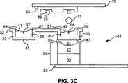
次いで、図3Cに示されるように、基材ウェルプレート65は基材位置合わせ手段70によって再度位置合わせされ、その結果、基材ウェル77はレザバウェル35の真上に位置付けられ、そこから液滴を受容する。図3Cはまた、イジェクター53が、イジェクター位置合わせ手段によってレザバウェル35の下に再度位置合わせされており、音波カップリング媒体61を介してイジェクターとレザバとを音波的にカップリングする。基材ウェルプレートおよびレザバウェルプレートは異なるサイズにされるので、イジェクター位置合わせ手段の動きと基材ウェルプレートの動きとの間に一致はなく、対応のみがある。一旦、図3Cに示されるように適切に整列されると、イジェクター53の音波照射発生装置55を作動して音波を生じ、この音波は次いで、集束手段57によって、流体表面39付近の焦点へと指向され、この流体表面39から液滴73が基材ウェルプレートの第2ウェル上に射出される。このような操作が、本発明のデバイスを使用して、1つのウェルプレートから異なるサイズの別のものへと複数の流体を移送し得る方法の例示であることは、はっきりと理解されるべきである。当業者は、イジェクターおよび基材の両方が連続動作中である場合でさえこの型の移送を実効し得ることを認識する。レザバ、ウェルプレートおよび/または基材の種々の組み合わせを、本発明のデバイスを使用する際に使用して、流体の移送に関与し得ることは、さらにはっきりと理解されるべきである。任意のレザバが、さらなる流体移送(例えば、アレイの沈着)のためにレザバを配備する前に、音波性射出を介して流体で充填され得ることは、さらにはっきりと理解されるべきである。
Then, as shown in FIG. 3C, the
上記に考察されるように、個々の、例えば、取り外し可能な、レザバまたはウェルプレートのいずれかを使用して、射出されるべき流体を収容し得、ここで、これらのレザバまたはウェルプレートのウェルは、好ましくは、実質的に音波で互いを区別不能である。また、イジェクターが射出される流体中に浸漬されることが意図されない限り、これらレザバまたはウェルプレートは、イジェクターからの音波放射が射出される流体の表面へと運搬されることを可能にするのに十分な音波伝播特性を有さなければならない。代表的に、このことは、レザバまたはウェルベース(これは、音波放射が受容不能な浪費なしにそれを介して移動することを可能にするために、十分に薄い)を提供する工程を包含する。さらに、レザバの構築において使用される材料は、その中に収容される液体と適合性でなければならない。従って、レザバまたはウェルがアセトニトリルのような有機溶媒を収容することが意図される場合、アセトニトリル中で溶解するかまたは膨潤するポリマーは、レザバもウェルプレートを形成する際に使用するのに不適切である。水ベースの流体について、多くの材料がレザバの構築に適切であり、そして酸化シリコンおよび酸化アルミニウムのようなセラミック、ステンレス鋼および白金のような金属、およびポリエステルおよびポリテトラフルオロエチレンのようなポリマーが挙げられるが、これらに限定されない。 As discussed above, either individual, for example, removable, reservoirs or well plates can be used to contain the fluid to be ejected, where the wells of these reservoirs or well plates Are preferably substantially indistinguishable from each other by sound waves. In addition, unless the ejector is intended to be immersed in the fluid to be ejected, these reservoirs or well plates allow sonic radiation from the ejector to be transported to the surface of the fluid to be ejected. It must have sufficient sound propagation characteristics. Typically this involves providing a reservoir or well base, which is thin enough to allow sound radiation to travel through it without unacceptable waste. . Furthermore, the materials used in the construction of the reservoir must be compatible with the liquid contained therein. Thus, if the reservoir or well is intended to contain an organic solvent such as acetonitrile, a polymer that dissolves or swells in acetonitrile is not suitable for use in forming the well plate as well. is there. For water-based fluids, many materials are suitable for reservoir construction, and ceramics such as silicon oxide and aluminum oxide, metals such as stainless steel and platinum, and polymers such as polyester and polytetrafluoroethylene are available. For example, but not limited to.
本発明のデバイスと共に使用するのに適切な多くのウェルプレートは市販されており、そして例えば、ウェルプレート当たり、96ウェル、384ウェルまたは1536ウェルを備え得る。本発明のデバイスにおける使用に適切なウェルプレートの製造業者としては、Corning Inc.(Corning,New York)およびGreinaer America,Inc(Lake Mary,Florida)が挙げられる。しかし、このような市販のウェルプレートの利用は、少なくとも約10,000ウェルを備えるカスタムメイドのウェルプレートの製造および使用でも、約100,000ウェル以上であっても、不可能ではない。アレイ形成適用のために、約100,000〜約4,000,000のレザバを使用し得ることが予想される。さらに、各レザバまたはレザバのウェルとイジェクターを整列させるために必要とされる移動量を低減するために、各レザバの中心が、他のいずれかのレザバの中心から、約1cm以下に位置付けられることが好ましく、好ましくは約1mm以下、そして最適には約0.5mm以下である。 Many well plates suitable for use with the devices of the present invention are commercially available and can comprise, for example, 96, 384 or 1536 wells per well plate. Manufacturers of well plates suitable for use in the devices of the present invention include Corning Inc. (Corning, New York) and Greiner America, Inc. (Lake Mary, Florida). However, the use of such commercially available well plates is not impossible, either for the manufacture and use of custom made well plates with at least about 10,000 wells, or more than about 100,000 wells. It is anticipated that about 100,000 to about 4,000,000 reservoirs may be used for array forming applications. In addition, the center of each reservoir should be positioned about 1 cm or less from the center of any other reservoir to reduce the amount of movement required to align each reservoir or reservoir well and ejector. Is preferred, preferably about 1 mm or less, and optimally about 0.5 mm or less.
さらに、このデバイスは、実質的に任意の型および所望される量の流体を射出するように適合され得る。この流体は、水性および/または非水性であり得る。非水性流体としては、例えば、水、有機溶媒、および脂質流体が挙げられ、そして、本発明は高温での使用に容易に適用されるので、液体金属、セラミック材料およびガラスのような流体が使用され得る;例えば、同時継続中の公開された米国特許出願第US2002/0037375号(「Focused Acoustic Energy Method and Device for Generating Droplets of Immiscible Fluids」)(発明者EllsonおよびMutzおよびFoote,2002年3月28日公開、およびPicoliter,Inc.(Mountain View,California)に譲渡された)を参照のこと。このような材料の微細な液滴を作製する能力は、圧電システムが上昇した温度で最適以下に機能する限り、圧電技術と際立って対照的である。さらに、本発明の技術を使用することが可能な正確さに起因して、このデバイスを使用して、約100nl以下の流体(好ましくは、10nl以下の流体)を収容するように適合されたレザバから、液滴を射出し得る。特定の場合において、このイジェクターは、約1nl〜約100nlの流体を収容するように適合されたレザバから液滴を射出するように適合され得る。これは、射出される流体が、稀または高価な生体分子を含む場合に特に有用であり、ここで、約1plまでの容量を有する液滴を射出することが望ましくあり得る。大きなF番号のレンズが、流体の表面に対する距離の比率がレザバの基部内に備えられた開口部よりもずっと大きい(すなわち、3〜5倍大きい)レザバから液滴を射出する能力は、0.01pl〜20plまでを任意の場所に収容するように適合された液滴の射出を可能にする。 Further, the device can be adapted to eject virtually any type and desired amount of fluid. The fluid can be aqueous and / or non-aqueous. Non-aqueous fluids include, for example, water, organic solvents, and lipid fluids, and fluids such as liquid metals, ceramic materials, and glass are used because the present invention is readily applied for use at high temperatures. For example, co-published published US Patent Application No. US2002 / 0037375 (“Focused Acoustic Energy Method and Device for Generating Droplets of Immiscible Fluids”, Inventors E2 See Nikkan, and Picolitter, Inc. (assigned to Mountain View, California). The ability to produce such fine droplets of material is in sharp contrast to piezoelectric technology, as long as the piezoelectric system functions suboptimally at elevated temperatures. Furthermore, due to the accuracy with which the techniques of the present invention can be used, a reservoir adapted to contain no more than about 100 nl of fluid (preferably no more than 10 nl of fluid) using this device. From which droplets can be ejected. In certain cases, the ejector can be adapted to eject droplets from a reservoir adapted to contain about 1 nl to about 100 nl of fluid. This is particularly useful when the ejected fluid contains rare or expensive biomolecules, where it may be desirable to eject droplets having a volume up to about 1 pl. The ability of a large F-number lens to eject droplets from a reservoir where the ratio of the distance to the surface of the fluid is much larger (ie, 3-5 times larger) than the opening provided in the reservoir base is 0. Enables ejection of droplets adapted to accommodate anywhere from 01 pl to 20 pl.
上記から、デバイスの種々の構成要素が、基材上でアレイを形成するために、個々の制御または同調を必要とし得ることは、明らかである。例えば、イジェクター位置合わせ手段は、基材表面上に調製されるアレイと関連して、予め決定したシーケンスで、各レザバから液滴を射出するように適合され得る。同様に、イジェクターに対して、基材表面を位置合わせするための基材位置合わせ手段は、その上のパターンまたはアレイで液滴を受容するために基材表面を位置合わせするように適合され得る。位置合わせ手段のいずれかまたは両方(すなわち、イジェクター位置決め手段および基材位置決め手段)は、例えば、レバー、プーリー、ギア、それらの組み合わせ、または当業者に公知の他の機械的手段から構築され得る。適切なパターン形成を確実にするために、基材の動作、イジェクターの動作、およびイジェクターの作動の間に対応があることを、確実にすることが好ましい。 From the above it is clear that the various components of the device may require individual control or tuning to form an array on the substrate. For example, the ejector alignment means can be adapted to eject droplets from each reservoir in a predetermined sequence in conjunction with an array prepared on the substrate surface. Similarly, with respect to the ejector, the substrate alignment means for aligning the substrate surface can be adapted to align the substrate surface for receiving droplets in a pattern or array thereon. . Either or both of the alignment means (ie, ejector positioning means and substrate positioning means) can be constructed from, for example, levers, pulleys, gears, combinations thereof, or other mechanical means known to those skilled in the art. In order to ensure proper patterning, it is preferable to ensure that there is a correspondence between substrate operation, ejector operation, and ejector operation.
さらに、このデバイスは、能力を増強させる他の構成要素を備え得る。例えば、上記に暗示されるように、このデバイスはさらに、例えば、基材に付着する液滴の射出を確実とするために、基材表面の温度を低下させるための冷却手段を備える。この冷却手段は、流体が基材と接触した後に、流体が部分的にかまたは好ましくは実質的に固化することを可能にする温度に、基材表面を維持するように適合され得る。水性流体の場合、この冷却手段は約0℃に基材表面を維持する能力を有するべきである。さらに、流体のレザバへの音波エネルギーの繰り返しの適用は、流体の加熱を生じ得る。加熱は勿論、速度、表面張力および密度のような流体の特性の所望されない変化を生じる。従って、このデバイスはさらに、レザバ中の流体を一定温度に維持するための手段を備え得る。このような温度維持手段の設計および構築は、当業者に公知であり、そして例えば、加熱要素、冷却要素、またはそれらの組み合わせのような構成要素を備え得る。多くの生体分子の沈着適用について、一般的に、生体分子を含む流体を、一定温度で、この温度から約1℃〜2℃より大きく偏ることなく保つことが所望される。さらに、特に熱に感受性の生体分子流体について、この流体を、流体の融点より高く約10℃を越えない温度に保たれることが好ましく、好ましくは、流体の融点より高く約5℃を越えない温度である。従って、例えば、生体分子含有流体が水性である場合、射出の間、流体を約4℃に保つことが最適であり得る。 In addition, the device may include other components that enhance capacity. For example, as implied above, the device further comprises cooling means for reducing the temperature of the substrate surface, for example to ensure ejection of droplets that adhere to the substrate. The cooling means may be adapted to maintain the substrate surface at a temperature that allows the fluid to partially or preferably substantially solidify after the fluid contacts the substrate. For aqueous fluids, this cooling means should have the ability to maintain the substrate surface at about 0 ° C. Further, repeated application of sonic energy to a fluid reservoir can result in heating of the fluid. Heating, of course, produces undesirable changes in fluid properties such as speed, surface tension and density. Thus, the device may further comprise means for maintaining the fluid in the reservoir at a constant temperature. The design and construction of such temperature maintaining means is known to those skilled in the art and may comprise components such as, for example, heating elements, cooling elements, or combinations thereof. For many biomolecule deposition applications, it is generally desirable to keep the fluid containing the biomolecules at a constant temperature without deviating more than about 1 ° C. to 2 ° C. from this temperature. Further, particularly for heat sensitive biomolecular fluids, it is preferred that the fluid be kept at a temperature above the melting point of the fluid and not exceeding about 10 ° C., preferably not exceeding about 5 ° C. above the melting point of the fluid. Temperature. Thus, for example, if the biomolecule-containing fluid is aqueous, it may be optimal to keep the fluid at about 4 ° C. during ejection.
本発明のデバイスは、同一のレザバから1分間当たり少なくとも約1,000,000滴の速度で、そして異なるレザバから1分間当たり少なくとも約100,000滴の速度で、液滴の射出を可能とする。さらに、現在の位置合わせ技術は、イジェクター位置合わせ手段が、1つのレザバから別のレザバへと速くかつ制御された様式で移動することを可能とし、それにより、異なる流体の速くかつ制御された射出を可能にする。すなわち、現在市販される技術は、各レザバで繰り返し可能でかつ制御された音波カップリングで、高性能位置合わせ手段については約0.1秒未満に、そして通常の位置合わせ手段については約1秒未満で、イジェクターが1つのレザバから別のレザバへと移動されることを可能とする。カスタム指定されたシステムは、繰り返し可能でかつ制御された音波カップリングで、約0.001秒未満で、イジェクターが1つのレザバから別のレザバへと移動されることを可能にする。カスタム指定されたシステムを提供するために、2つの基本的な動作(パルス的および継続的)があることを覚えておくことが重要である。パルス動作はイジェクターを所定位置に移動させる別々工程、音波エネルギーを射出する工程、およびイジェクターを次の位置に移動させる工程を包含する;かさねて、このような方法と共に高性能位置合わせ手段を使用することは、0.1秒未満で、各レザバでの繰り返し可能でかつ制御された音波カップリング可能にする。一方で、継続的動作設計は、イジェクターおよびレザバを継続的に移動させるが、同じ速度ではなく、そして移動の間に射出を提供する。パルスの幅は非常に短いので、この型のプロセスは10Hzより多くのレザバのトランジションを可能とし、そして1000Hzより高いレザバのトランジションを可能にする。 The device of the present invention allows droplet ejection at the rate of at least about 1,000,000 drops per minute from the same reservoir and at the rate of at least about 100,000 drops per minute from different reservoirs. . Furthermore, current alignment techniques allow ejector alignment means to move from one reservoir to another in a fast and controlled manner, thereby allowing fast and controlled ejection of different fluids. Enable. That is, currently available technology is repeatable and controlled sonic coupling at each reservoir, less than about 0.1 seconds for high performance alignment means, and about 1 second for normal alignment means. Less than allows an ejector to be moved from one reservoir to another. Custom-designed systems allow repeaters to be moved from one reservoir to another in less than about 0.001 seconds with repeatable and controlled sonic coupling. It is important to remember that there are two basic actions (pulsed and continuous) to provide a custom specified system. The pulsing operation includes a separate step of moving the ejector to a predetermined position, a step of emitting sonic energy, and a step of moving the ejector to the next position; This allows repeatable and controlled sonic coupling at each reservoir in less than 0.1 seconds. On the other hand, the continuous motion design moves the ejector and reservoir continuously but not at the same speed and provides injection during the movement. Since the pulse width is very short, this type of process allows reservoir transitions greater than 10 Hz and reservoir transitions higher than 1000 Hz.
本発明はその好ましい特定の実施形態と組み合わせて記載されているが、前出の記載は本発明の範囲を例示することが意図され、これを限定するものではない。他の局面、利点および改変は、本発明が関係する分野の当業者に明かである。 While this invention has been described in combination with specific preferred embodiments thereof, the preceding description is intended to illustrate the scope of the invention and is not intended to limit it. Other aspects, advantages, and modifications will be apparent to those skilled in the art to which this invention pertains.
Claims (59)
(a) 流体を収容するように適合され、そして実質的に均一な様式で集束された音波エネルギーの伝播を可能とする開口部を有するレザバであって、該開口部が横断面の幅を有する、レザバ;および
(b) 音波放射を形成するための音波放射発生装置、および流体レザバ内に収容された流体の表面から液滴を射出するために、形成された音波放射を集束させ得る集束手段から構成されるイジェクターであって、該流体の表面が該開口部から距離dにある、イジェクター、
を備え、ここで、該距離d 対 該開口部の該横断面の幅の比率が、約2:1より大きい、デバイス。A device for ejecting a droplet of fluid by acoustic waves toward a designated site on a substrate surface, the device comprising:
(A) is adapted to contain a fluid, and a reservoir having an opening portion for allowing substantially focused sonic energy in a uniform manner the propagation, the opening portion has a width in the transverse cross-section And (b) a sound wave radiation generator for forming sound wave radiation, and a focusing means capable of focusing the formed sound wave radiation to eject droplets from the surface of a fluid contained in the fluid reservoir a ejector consists, the surface of the fluid from the opening to a distance d, ejector,
Wherein the ratio of the distance d to the width of the cross-section of the opening is greater than about 2: 1.
(c) 前記レザバに対して音波カップリングする関係で前記イジェクター(i)を位置合わせするための手段
を備える、デバイス。The device of claim 1, further comprising:
(C) A device comprising means for aligning the ejector (i) in a sonic coupling relationship with the reservoir.
(a) デバイスを提供する工程であって、該デバイスは:
(i) 第1の流体を収容するレザバであって、該レザバが、実質的に均一な様式で音波エネルギーの伝播を可能とする開口部を有し、該開口部が、横断面の幅を有する、レザバ;および
(ii) 音波放射を形成するための音波放射発生装置、および流体レザバ内に収容された該第1の流体の表面から液滴を射出するために、形成された音波放射を集束させ得る集束手段から構成される、イジェクターであって、該表面が、該開口部から距離dにある、イジェクター、
から構成され、
ここで、該集束手段からの該距離d 対 該開口部の該横断面の幅の比率が、約2:1より大きい、工程;
(b) 該流体収容レザバと、音波的にカップリングした関係にあるようにイジェクターを位置合わせする工程であって、ここで、該イジェクターの位置は、該音波エネルギーを該第1の流体の表面近くに集束させるように、該集束手段を置く、工程;ならびに
(c) 該イジェクターを作動して、集束した音波放射を形成し、これによって該レザバから該第1の流体の液滴を射出し、該第1の流体の表面における該集束された音波放射の焦点スポットの直径がDである、工程
を包含する、方法。A method for ejecting fluid from a fluid reservoir toward a designated site on a substrate surface, the method comprising:
(A) providing a device , the device comprising:
(I) a reservoir for containing a first fluid, said reservoirs has an opening which allows the propagation of acoustic energy in a substantially uniform manner, the opening is, the width of the transverse cross-section And (ii) a sonic radiation generator for generating sonic radiation, and a sonic radiation formed to eject droplets from the surface of the first fluid contained within the fluid reservoir. An ejector comprising a focusing means capable of focusing, wherein the surface is at a distance d from the opening;
Consisting of
Wherein the ratio of the distance d from the focusing means to the width of the cross section of the opening is greater than about 2: 1;
(B) aligning an ejector with the fluid containing reservoir in a sonically coupled relationship, wherein the position of the ejector determines the sonic energy on the surface of the first fluid; as focusing nearby, placing the focusing means, step, and actuates the (c) the ejector, to form a focused acoustic radiation, thereby injecting a droplet of fluid first from the reservoir The diameter of the focal spot of the focused acoustic radiation at the surface of the first fluid is D.
(d) 第2の流体を収容する第2の流体収容レザバに対して、音波的にカップリングした関係にあるようにイジェクターを位置合わせする、工程;および
(e) 工程(b)のように、該イジェクターを作動して、該基材表面上の第2の指定された部位に向けて、該第2のレザバから該第2流体の液滴を射出する、工程
を包含する、方法。40. The method of claim 38, wherein the device comprises a plurality of reservoirs, each adapted to contain a fluid, wherein the device comprises a plurality of reservoirs on the substrate surface. Fluid droplets can be ejected from each of the plurality of reservoirs toward a designated site, the method further comprising:
(D) aligning the ejector so as to be acoustically coupled to the second fluid containing reservoir containing the second fluid; and (e) as in step (b) Activating the ejector to eject droplets of the second fluid from the second reservoir toward a second designated site on the substrate surface.
Applications Claiming Priority (2)
| Application Number | Priority Date | Filing Date | Title |
|---|---|---|---|
| US09/910,690 US6416164B1 (en) | 2001-07-20 | 2001-07-20 | Acoustic ejection of fluids using large F-number focusing elements |
| PCT/US2002/017656 WO2003022583A1 (en) | 2001-07-20 | 2002-06-04 | Acoustic ejection of fluids using large f-number focusing elements |
Publications (3)
| Publication Number | Publication Date |
|---|---|
| JP2005502866A JP2005502866A (en) | 2005-01-27 |
| JP2005502866A5 JP2005502866A5 (en) | 2008-09-18 |
| JP4189964B2 true JP4189964B2 (en) | 2008-12-03 |
Family
ID=25429185
Family Applications (1)
| Application Number | Title | Priority Date | Filing Date |
|---|---|---|---|
| JP2003526688A Expired - Lifetime JP4189964B2 (en) | 2001-07-20 | 2002-06-04 | Sound ejection of fluid using a large F-number focusing element |
Country Status (6)
| Country | Link |
|---|---|
| US (1) | US6416164B1 (en) |
| EP (1) | EP1409254B1 (en) |
| JP (1) | JP4189964B2 (en) |
| CA (1) | CA2452470C (en) |
| ES (1) | ES2651538T3 (en) |
| WO (1) | WO2003022583A1 (en) |
Families Citing this family (43)
| Publication number | Priority date | Publication date | Assignee | Title |
|---|---|---|---|---|
| US6666541B2 (en) * | 2000-09-25 | 2003-12-23 | Picoliter Inc. | Acoustic ejection of fluids from a plurality of reservoirs |
| JP4990476B2 (en) * | 2000-09-25 | 2012-08-01 | ピコリター インコーポレイテッド | Focused acoustic energy in the preparation and screening of combinatorial libraries |
| US6893836B2 (en) * | 2000-11-29 | 2005-05-17 | Picoliter Inc. | Spatially directed ejection of cells from a carrier fluid |
| US6849423B2 (en) * | 2000-11-29 | 2005-02-01 | Picoliter Inc | Focused acoustics for detection and sorting of fluid volumes |
| US7332127B2 (en) * | 2001-07-11 | 2008-02-19 | University Of Southern California | DNA probe synthesis on chip on demand by MEMS ejector array |
| US7354141B2 (en) * | 2001-12-04 | 2008-04-08 | Labcyte Inc. | Acoustic assessment of characteristics of a fluid relevant to acoustic ejection |
| US6893115B2 (en) | 2002-09-20 | 2005-05-17 | Picoliter Inc. | Frequency correction for drop size control |
| US6874699B2 (en) * | 2002-10-15 | 2005-04-05 | Wisconsin Alumni Research Foundation | Methods and apparata for precisely dispensing microvolumes of fluids |
| US6979073B2 (en) | 2002-12-18 | 2005-12-27 | Xerox Corporation | Method and apparatus to pull small amounts of fluid from n-well plates |
| US6827287B2 (en) * | 2002-12-24 | 2004-12-07 | Palo Alto Research Center, Incorporated | High throughput method and apparatus for introducing biological samples into analytical instruments |
| US6916083B2 (en) * | 2003-09-22 | 2005-07-12 | Labcyte Inc. | Control over flow of an acoustic coupling fluid |
| US7070260B2 (en) * | 2003-01-09 | 2006-07-04 | Labcyte Inc. | Droplet dispensation from a reservoir with reduction in uncontrolled electrostatic charge |
| JP2007533647A (en) * | 2003-10-24 | 2007-11-22 | アルザ・コーポレーシヨン | Preparation of lipid particles |
| US7334871B2 (en) * | 2004-03-26 | 2008-02-26 | Hewlett-Packard Development Company, L.P. | Fluid-ejection device and methods of forming same |
| US10112212B1 (en) | 2004-04-08 | 2018-10-30 | Labcyte Inc. | Droplet ejection using focused acoustic radiation having a plurality of frequency ranges |
| US7445315B2 (en) * | 2004-11-15 | 2008-11-04 | Palo Alto Research Center Incorporated | Thin film and thick film heater and control architecture for a liquid drop ejector |
| US20060210443A1 (en) | 2005-03-14 | 2006-09-21 | Stearns Richard G | Avoidance of bouncing and splashing in droplet-based fluid transport |
| US7607347B2 (en) * | 2006-03-07 | 2009-10-27 | Gems Sensors, Inc. | Fluid level detector |
| EP2021103B1 (en) | 2006-05-09 | 2017-07-12 | Advanced Liquid Logic, Inc. | Electrowetting droplet microactuator controlled via graphical user interface |
| US8053191B2 (en) | 2006-08-31 | 2011-11-08 | Westend Asset Clearinghouse Company, Llc | Iterative nucleic acid assembly using activation of vector-encoded traits |
| US9192932B2 (en) * | 2007-06-20 | 2015-11-24 | Labcyte Inc. | Closures which contain reservoirs and allow acoustic ejection |
| US7753636B2 (en) * | 2008-03-25 | 2010-07-13 | Hennig Emmett D | Adjustable bale mover spikes |
| WO2010025310A2 (en) | 2008-08-27 | 2010-03-04 | Westend Asset Clearinghouse Company, Llc | Methods and devices for high fidelity polynucleotide synthesis |
| US10207240B2 (en) | 2009-11-03 | 2019-02-19 | Gen9, Inc. | Methods and microfluidic devices for the manipulation of droplets in high fidelity polynucleotide assembly |
| WO2011066185A1 (en) | 2009-11-25 | 2011-06-03 | Gen9, Inc. | Microfluidic devices and methods for gene synthesis |
| ES2574055T3 (en) | 2009-11-25 | 2016-06-14 | Gen9, Inc. | Methods and apparatus for error reduction in chip-based DNA |
| US9217144B2 (en) | 2010-01-07 | 2015-12-22 | Gen9, Inc. | Assembly of high fidelity polynucleotides |
| US10457935B2 (en) | 2010-11-12 | 2019-10-29 | Gen9, Inc. | Protein arrays and methods of using and making the same |
| EP3360963B1 (en) | 2010-11-12 | 2019-11-06 | Gen9, Inc. | Methods and devices for nucleic acids synthesis |
| US9752176B2 (en) | 2011-06-15 | 2017-09-05 | Ginkgo Bioworks, Inc. | Methods for preparative in vitro cloning |
| AU2012300401B2 (en) | 2011-08-26 | 2018-02-08 | Gen9, Inc. | Compositions and methods for high fidelity assembly of nucleic acids |
| US9150853B2 (en) | 2012-03-21 | 2015-10-06 | Gen9, Inc. | Methods for screening proteins using DNA encoded chemical libraries as templates for enzyme catalysis |
| WO2013163263A2 (en) | 2012-04-24 | 2013-10-31 | Gen9, Inc. | Methods for sorting nucleic acids and multiplexed preparative in vitro cloning |
| CN104685116A (en) | 2012-06-25 | 2015-06-03 | Gen9股份有限公司 | Methods for nucleic acid assembly and high throughput sequencing |
| US10156499B1 (en) | 2012-10-01 | 2018-12-18 | Labcyte Inc. | Focused acoustic radiation for the ejection of subwavelength droplets |
| CN106661535B (en) * | 2014-01-21 | 2021-03-02 | 普罗美迪卡生物电子学公司 | Apparatus for ultrasonic testing |
| EP3207374B1 (en) | 2014-10-17 | 2021-05-12 | Labcyte Inc. | Method and system for determining the concentration of an analyte in a fluid sample |
| JP6861803B2 (en) | 2016-09-15 | 2021-04-21 | ラブサイト インコーポレイテッド | High-efficiency transfection of biological cells using sonoporation |
| AU2018374058A1 (en) | 2017-11-22 | 2020-06-18 | Dh Technologies Development Pte. Ltd. | System and method for the acoustic loading of an analytical instrument using a continuous flow sampling probe |
| EP3762491B1 (en) | 2018-03-03 | 2023-09-20 | Labcyte Inc. | Method for extracting a target moiety from a sample using acoustic droplet ejection |
| KR20230074600A (en) | 2018-03-30 | 2023-05-30 | 랩사이트 아이엔씨. | Fluid impermeable ultrasonic transducer |
| CN113195102B (en) * | 2018-10-29 | 2023-09-15 | 拉伯赛特股份有限公司 | Acoustic droplet ejection of non-Newtonian fluids |
| WO2023218330A1 (en) * | 2022-05-10 | 2023-11-16 | Dh Technologies Development Pte. Ltd. | Systems and methods for automatic sample re-runs in sample analysys |
Family Cites Families (14)
| Publication number | Priority date | Publication date | Assignee | Title |
|---|---|---|---|---|
| US4308547A (en) | 1978-04-13 | 1981-12-29 | Recognition Equipment Incorporated | Liquid drop emitter |
| US4697195A (en) | 1985-09-16 | 1987-09-29 | Xerox Corporation | Nozzleless liquid droplet ejectors |
| US4697105A (en) | 1986-07-23 | 1987-09-29 | American Telephone And Telegraph Company, At&T Bell Laboratories | CMOS programmable logic array |
| US4751529A (en) | 1986-12-19 | 1988-06-14 | Xerox Corporation | Microlenses for acoustic printing |
| US5041849A (en) | 1989-12-26 | 1991-08-20 | Xerox Corporation | Multi-discrete-phase Fresnel acoustic lenses and their application to acoustic ink printing |
| US5229793A (en) * | 1990-12-26 | 1993-07-20 | Xerox Corporation | Liquid surface control with an applied pressure signal in acoustic ink printing |
| JPH11151810A (en) * | 1997-11-21 | 1999-06-08 | Toshiba Corp | Ink jet recording device |
| US6364454B1 (en) * | 1998-09-30 | 2002-04-02 | Xerox Corporation | Acoustic ink printing method and system for improving uniformity by manipulating nonlinear characteristics in the system |
| ATE315957T1 (en) * | 2000-09-25 | 2006-02-15 | Picoliter Inc | SOUND EXHAUST OF FLUID FROM SEVERAL CONTAINER |
| US20020061258A1 (en) | 2000-09-25 | 2002-05-23 | Mutz Mitchell W. | Focused acoustic energy in the preparation and screening of combinatorial libraries |
| US6666541B2 (en) | 2000-09-25 | 2003-12-23 | Picoliter Inc. | Acoustic ejection of fluids from a plurality of reservoirs |
| US6548308B2 (en) | 2000-09-25 | 2003-04-15 | Picoliter Inc. | Focused acoustic energy method and device for generating droplets of immiscible fluids |
| US6806051B2 (en) | 2000-09-25 | 2004-10-19 | Picoliter Inc. | Arrays of partially nonhybridizing oligonucleotides and preparation thereof using focused acoustic energy |
| US6596239B2 (en) * | 2000-12-12 | 2003-07-22 | Edc Biosystems, Inc. | Acoustically mediated fluid transfer methods and uses thereof |
-
2001
- 2001-07-20 US US09/910,690 patent/US6416164B1/en not_active Expired - Lifetime
-
2002
- 2002-06-04 CA CA002452470A patent/CA2452470C/en not_active Expired - Lifetime
- 2002-06-04 JP JP2003526688A patent/JP4189964B2/en not_active Expired - Lifetime
- 2002-06-04 WO PCT/US2002/017656 patent/WO2003022583A1/en active Application Filing
- 2002-06-04 ES ES02739673.8T patent/ES2651538T3/en not_active Expired - Lifetime
- 2002-06-04 EP EP02739673.8A patent/EP1409254B1/en not_active Expired - Lifetime
Also Published As
| Publication number | Publication date |
|---|---|
| JP2005502866A (en) | 2005-01-27 |
| CA2452470C (en) | 2009-12-08 |
| ES2651538T3 (en) | 2018-01-29 |
| US6416164B1 (en) | 2002-07-09 |
| CA2452470A1 (en) | 2003-03-20 |
| EP1409254B1 (en) | 2017-09-13 |
| WO2003022583A1 (en) | 2003-03-20 |
| EP1409254A1 (en) | 2004-04-21 |
Similar Documents
| Publication | Publication Date | Title |
|---|---|---|
| JP4189964B2 (en) | Sound ejection of fluid using a large F-number focusing element | |
| US20020064808A1 (en) | Focused acoustic energy for ejecting cells from a fluid | |
| US6938987B2 (en) | Acoustic ejection of fluids from a plurality of reservoirs | |
| CA2423063C (en) | Focused acoustic energy in the preparation and screening of combinatorial libraries | |
| CA1282281C (en) | Spatially addressable capillary wave droplet ejectors and the like | |
| US6603118B2 (en) | Acoustic sample introduction for mass spectrometric analysis | |
| US20020037375A1 (en) | Focused acoustic energy method and device for generating droplets of immiscible fluids | |
| JP2005502866A5 (en) | ||
| JPH071732A (en) | Printing head | |
| US6746104B2 (en) | Method for generating molecular arrays on porous surfaces | |
| EP1870157A2 (en) | Focused acoustic energy in the preparation and screening of combinatorial libraries | |
| CA2423068C (en) | Acoustic ejection of fluids from a plurality of reservoirs | |
| US10800170B1 (en) | Droplet ejection using focused acoustic radiation having a plurality of frequency ranges | |
| JP4955901B2 (en) | Focused acoustic energy method and device for generating droplets of immiscible fluids | |
| US20040056931A1 (en) | Frequency correction for drop size control | |
| JP2003121440A (en) | Manufacturing method of reactive chip and micro-droplet discharge device used for method | |
| US20020085063A1 (en) | Focused acoustic energy in the preparation and screening of combinatorial libraries | |
| JPH01157861A (en) | Acoustic micro-streaming in ink jet device | |
| JP2005246663A (en) | Liquid ejection head and driving method therefor | |
| EP1614461A2 (en) | Acoustic ejection of fluids from reservoirs | |
| JPH01242261A (en) | Liquid jet recording head | |
| JPS60239248A (en) | Optical inkjet head | |
| JPH01238948A (en) | Liquid jet recording head |
Legal Events
| Date | Code | Title | Description |
|---|---|---|---|
| A621 | Written request for application examination |
Free format text: JAPANESE INTERMEDIATE CODE: A621 Effective date: 20050602 |
|
| A131 | Notification of reasons for refusal |
Free format text: JAPANESE INTERMEDIATE CODE: A131 Effective date: 20080204 |
|
| A601 | Written request for extension of time |
Free format text: JAPANESE INTERMEDIATE CODE: A601 Effective date: 20080422 |
|
| A602 | Written permission of extension of time |
Free format text: JAPANESE INTERMEDIATE CODE: A602 Effective date: 20080430 |
|
| A524 | Written submission of copy of amendment under article 19 pct |
Free format text: JAPANESE INTERMEDIATE CODE: A524 Effective date: 20080801 |
|
| TRDD | Decision of grant or rejection written | ||
| A01 | Written decision to grant a patent or to grant a registration (utility model) |
Free format text: JAPANESE INTERMEDIATE CODE: A01 Effective date: 20080828 |
|
| A521 | Request for written amendment filed |
Free format text: JAPANESE INTERMEDIATE CODE: A821 Effective date: 20080801 |
|
| A01 | Written decision to grant a patent or to grant a registration (utility model) |
Free format text: JAPANESE INTERMEDIATE CODE: A01 |
|
| A61 | First payment of annual fees (during grant procedure) |
Free format text: JAPANESE INTERMEDIATE CODE: A61 Effective date: 20080911 |
|
| FPAY | Renewal fee payment (event date is renewal date of database) |
Free format text: PAYMENT UNTIL: 20110926 Year of fee payment: 3 |
|
| R150 | Certificate of patent or registration of utility model |
Ref document number: 4189964 Country of ref document: JP Free format text: JAPANESE INTERMEDIATE CODE: R150 Free format text: JAPANESE INTERMEDIATE CODE: R150 |
|
| FPAY | Renewal fee payment (event date is renewal date of database) |
Free format text: PAYMENT UNTIL: 20120926 Year of fee payment: 4 |
|
| R250 | Receipt of annual fees |
Free format text: JAPANESE INTERMEDIATE CODE: R250 |
|
| FPAY | Renewal fee payment (event date is renewal date of database) |
Free format text: PAYMENT UNTIL: 20130926 Year of fee payment: 5 |
|
| R250 | Receipt of annual fees |
Free format text: JAPANESE INTERMEDIATE CODE: R250 |
|
| R250 | Receipt of annual fees |
Free format text: JAPANESE INTERMEDIATE CODE: R250 |
|
| R250 | Receipt of annual fees |
Free format text: JAPANESE INTERMEDIATE CODE: R250 |
|
| R250 | Receipt of annual fees |
Free format text: JAPANESE INTERMEDIATE CODE: R250 |
|
| R250 | Receipt of annual fees |
Free format text: JAPANESE INTERMEDIATE CODE: R250 |
|
| R250 | Receipt of annual fees |
Free format text: JAPANESE INTERMEDIATE CODE: R250 |
|
| R250 | Receipt of annual fees |
Free format text: JAPANESE INTERMEDIATE CODE: R250 |
|
| R250 | Receipt of annual fees |
Free format text: JAPANESE INTERMEDIATE CODE: R250 |
|
| R250 | Receipt of annual fees |
Free format text: JAPANESE INTERMEDIATE CODE: R250 |
|
| R250 | Receipt of annual fees |
Free format text: JAPANESE INTERMEDIATE CODE: R250 |
|
| EXPY | Cancellation because of completion of term |