JP4189727B2 - Vehicle steering system - Google Patents
Vehicle steering system Download PDFInfo
- Publication number
- JP4189727B2 JP4189727B2 JP2002281669A JP2002281669A JP4189727B2 JP 4189727 B2 JP4189727 B2 JP 4189727B2 JP 2002281669 A JP2002281669 A JP 2002281669A JP 2002281669 A JP2002281669 A JP 2002281669A JP 4189727 B2 JP4189727 B2 JP 4189727B2
- Authority
- JP
- Japan
- Prior art keywords
- actuator
- steering
- rotation
- electric motor
- shaft
- Prior art date
- Legal status (The legal status is an assumption and is not a legal conclusion. Google has not performed a legal analysis and makes no representation as to the accuracy of the status listed.)
- Expired - Fee Related
Links
Images


Landscapes
- Steering Control In Accordance With Driving Conditions (AREA)
- Power Steering Mechanism (AREA)
- Steering Controls (AREA)
Description
【0001】
【発明の属する技術分野】
本発明は、操舵部材の操作に基づいて転舵輪を転舵させる車両用操舵装置に関するものである。
【0002】
【従来の技術】
ステアリングホイール等の操舵部材の操舵量に応じて転舵輪の転舵量の比(転舵比)を可変とする転舵比可変機構(VGRS: Variable Gear Ratio System )として、遊星ギヤ機構と、遊星ギヤ機構の例えばリングギヤを駆動する転舵比可変用の電動モータとを備える車両用操舵装置が種々提供されている(例えば、特許文献1参照。)。
【0003】
また、近年、ステアリングホイール等の操舵部材と転舵輪との間の機械的な連結を解き、操舵伝達系の一部を電気的な経路で構成する、いわゆるステア・バイ・ワイヤ・システム(単にSBWとも称する)の車両用操舵装置が提供されている(例えば、特許文献2参照。)。
【0004】
【特許文献1】
特開平5−77751号公報
【特許文献2】
特開平1−233170号公報
【0005】
【発明が解決しようとする課題】
しかしながら、上記のVGRSやSBWの車両用操舵装置では、例えば操舵用のアクチュエータとしての電動モータに断線等を生じたとき等に対するフェールセーフ対策が重要である。
本発明は上記課題に鑑みてなされたものであり、VGRSやSBWにおいて、操舵用アクチュエータの故障発生時にも良好な操舵を達成することができる車両用操舵装置を提供することを目的とする。
【0006】
【課題を解決するための手段及び発明の効果】
上記目的を達成するため、請求項1記載の発明は、操舵部材に連なる第1要素、転舵輪に連なる第2要素、並びに、第1及び第2要素を関連付ける第3要素を含む差動伝達機構と、転舵輪を転舵させるための第1アクチュエータと、差動伝達機構の第3要素に駆動伝達可能に連結される第2アクチュエータと、第2アクチュエータから上記第3要素への駆動伝達を、第2アクチュエータの回転軸の回転を減速させて、抑制することのできる抑制手段と、第2アクチュエータの回転軸の回転を回転不能に拘束する拘束手段と、上記第1アクチュエータの異常発生時に、上記抑制手段によって第2アクチュエータから上記第3要素への駆動伝達を所定時間抑制させた後に、拘束手段によって第2アクチュエータの回転を拘束する制御手段とを備えることを特徴とするものである。
【0007】
本発明では、通常時は、第2アクチュエータに適当なトルクを生じさせることで、差動伝達機構を介して操舵部材に適正な操舵反力を付与したり、或いは転舵比可変のために差動伝達機構の第3要素を駆動する。また、第1アクチュエータに異常が発生したときには、第2アクチュエータから差動伝達機構の上記第3要素への駆動伝達を抑制することで、差動伝達機構の残りの2つの要素による伝達比でのマニュアル操舵を達成することができる。第2アクチュエータが断線したり、暴走したりしている場合にも、確実にマニュアル操舵を実現することができる。
【0008】
請求項2記載の発明は、請求項1において、上記第2アクチュエータは電動モータを含み、上記拘束手段は、上記電動モータの回転軸に一体回転可能なラチェットとこのラチェットに係止可能な係止爪とを含み、上記抑制手段は上記電動モータの回転軸の回転を機械的に減速するための減速手段を含むことを特徴とするものである。本発明では、第1アクチュエータの異常発生時に第2アクチュエータとしての電動モータの回転軸の回転を減速手段によって減速し、係止爪をラチェットに係止させて回転軸を回転不能にロックすることで、差動伝達機構の残りの2つの要素による伝達比でのマニュアル操舵を達成することができる。減速手段と係止爪を併用するので、係止爪がラチェットに弾かれたり破損したりすることがなく、係止爪により確実に回転軸を回転不能にロックすることができる。
【0009】
請求項3記載の発明は、請求項1において、上記第2アクチュエータは電動モータを含み、上記抑制手段は、上記電動モータの回転軸の回転、又は第3要素に一体回転する第3要素の支軸の回転に摩擦抵抗を与えることのできる摩擦抵抗付与手段を含むことを特徴とする。本発明では、請求項1記載の発明と同様の効果を奏することができる。また、高速回転中の回転軸等であっても、この回転を減速できるので、回転軸等の回転を確実に抑制して、第1アクチュエータの異常発生時に確実にマニュアル操舵を達成することができる。
【0010】
請求項4記載の発明は、請求項1において、上記第2アクチュエータは電動モータを含み、上記抑制手段は、上記電動モータの回転軸に一体回転する回転側摩擦板と、この回転側摩擦板に摩擦結合可能な回動不能な固定側摩擦板とを含むことを特徴とするものである。本発明では、請求項1記載の発明と同様の効果を奏することができる。しかも、高速回転中の回転軸であっても、この回転を減速できるので、回転軸の回転を確実に抑制して、第1アクチュエータの異常発生時に確実にマニュアル操舵を達成することができる。
【0011】
【発明の実施の形態】
本発明の好ましい実施の形態を添付図面を参照しつつ説明する。
図1は本発明の一実施の形態の車両用操舵装置の概略構成を示す模式図である。図1を参照して、本車両用操舵装置1は、例えばステアリングホイール等の操舵部材2に一体回転可能に連結される第1操舵軸3と、この第1操舵軸3と同軸上に設けられラックアンドピニオン機構等の舵取り機構4に連結される第2操舵軸5と、第1及び第2操舵軸3,5間の差動回転を許容するための差動伝達機構を構成する遊星伝達機構としての遊星ギヤ機構6とを備える。
【0012】
舵取り機構4は、車両の左右方向に延びて配置された転舵軸7と、この転舵軸7の両端にタイロッド8を介して結合され、転舵輪9を支持するナックルアーム10とを備える。転舵軸7はハウジング11により支承されて軸方向に摺動可能とされており、その途中部に、電動モータからなる第1アクチュエータとしての操舵用アクチュエータ12が同軸的に組み込まれている。操舵用アクチュエータ12の駆動回転は、ボールねじ機構等の運動変換機構等によって転舵軸7の摺動に変換され、この転舵軸7の摺動により転舵輪9の転舵が達成される。
【0013】
転舵軸7の一部には、ラック7aが形成されており、このラック7aには、第2操舵軸5の端部に設けられて第2操舵軸5と一体回転するピニオン14が噛み合わされている。
遊星ギヤ機構6は、第1操舵軸3の端部に一体回転可能に連結された入力側となる第1要素(太陽部材)としての太陽ギヤ15と、出力側となる第2要素としてのキャリア16により回転自在に保持されて太陽ギヤ15と噛み合う(遊星部材)としての複数の遊星ギヤ17と、各遊星ギヤ17に噛み合う内歯18aを内周に持つリング部材としてのリングギヤ18とを含む。
【0014】
リングギヤ18は外歯18bを形成することで例えばウォームホイールを構成している。この外歯18bは例えばウォームからなる駆動伝達ギヤ19を介して、操舵部材2に操作反力を与えるための反力用アクチュエータ(第2アクチュエータ)としての電動モータ20に駆動連結されている。この電動モータ20のケーシング20aは車体の適所に固定され、このケーシング20aから延びる回転軸20bに上記の駆動伝達ギヤ19が一体回転可能に連結されている。
【0015】
本実施の形態の特徴とするところは、操舵用アクチュエータ12の異常発生時に、抑制手段としての例えば電磁ブレーキ21によって、電動モータ20の回転軸20bの回転を減速し、拘束手段としてのラチェット機構22によって、回転軸20bを回転不能に拘束するようにした点にある。
具体的には、抑制手段としての電磁ブレーキ21は、回転軸20bに摺接可能な摩擦体23と、この摩擦体23を進退駆動させるための駆動部材としての電磁式のプランジャ24とを備える。
【0016】
プランジャ24は、例えばステアリングコラム等の固定部材に固定される固定部25と、固定部25から突出してその先端に摩擦体23を固定する可動部26とを備え、ソレノイド27及び図示しない戻しばねを内蔵している。
プランジャ24の可動部26は、通常時は図示しない戻しばねの力で図1に示すように後退している。ソレノイド27に通電されることにより、可動部26が進出し、摩擦体23を回転軸20bに押し付けて制動トルクを与え、減速させる。なお、回転軸20bに一体回転可能なロータを設け、このロータの周面に摩擦体23を摺接させるようにしても良い。
【0017】
拘束手段としてのラチェット機構22は、電動モータ20の回転軸20bに一体回転可能に連結される、いわゆるつめ車としてのラチェット28と、このラチェット28に係止可能な係止爪29とを備える。係止爪29は駆動部材としての電磁式のプランジャ30によってラチェット28に係止する係止位置と係止を解除する解除位置とに駆動されるようになっている。プランジャ30の構成はプランジャ24と同様であり、固定部25、可動部26、ソレノイド27及び図示しない戻しばねを備えている。
【0018】
摩擦体23及びプランジャ24は1組であっても良いし、回転軸20bと同心の円周上に複数組を並べて配置しても良い。同様に、係止爪29とプランジャ30は1組であっても良いし、回転軸20bと同心の円周上に複数組を並べて配置しても良い。
操舵用アクチュエータ12、反力用アクチュエータ20、プランジャ24及びプランジャ30はCPU、ROM、RAM等を含む制御部Cによりそれぞれ対応する駆動回路31,32,33,34を介して制御されるようになっている。
【0019】
第1操舵軸3には操舵部材2による操舵角(操舵位置)を検出するための操舵位置センサとしての操舵角センサ35、及び操舵部材2から入力される操舵トルクを検出するためのトルクセンサ36が設けられている。これら操舵角センサ35及びトルクセンサ36からの検出信号が制御部Cに入力される。
また、転舵軸8には転舵軸7の軸方向位置に関連して転舵角(転舵位置)を検出するための転舵位置検出センサとしての転舵角センサ37が設けられており、この転舵角センサ37による検出信号も制御部Cに入力される。また、制御部Cには、車速を検出するための車速センサ38からの検出信号が入力されるようになっている。
【0020】
制御部Cは、上記各センサ類からの入力信号に基づいて、操舵用アクチュエータ12、反力用アクチュエータ20、プランジャ24及びプランジャ30をそれぞれ駆動するための駆動部としての駆動回路31,32,33,34に制御信号を出力する。
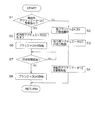
図2は制御部Cにより実行される舵取り制御の処理について説明するためのフローチャートである。図2を参照して、制御部Cは操舵用アクチュエータ12が正常に動作しているか否かを監視している(ステップS1)。
【0021】
操舵用アクチュエータ12に異常が発生していない場合には(ステップS1でNO)、電磁式のプランジャ24,30の励磁が解除されており(ステップS2)、反力用アクチュエータ20によって例えば路面反力に応じた操作反力を操舵部材2に与えるためのトルクを発生させる(ステップS3)。
また、例えば車両の走行状況等に応じて操舵部材2の回転量と転舵輪9の転舵量との比(伝達比、ギヤ比)を設定し(VGR機能)、この設定した伝達比及び操舵部材2の操作量などに基づいて、操舵用アクチュエータ12の電圧指令値を設定し、その電圧指令値に応じた制御信号を駆動回路31に与えて、操舵用アクチュエータ12を駆動制御する(ステップS4)。
【0022】
これにより、操舵用アクチュエータ12から、操舵部材2の操作方向に応じた方向に転舵軸7を摺動させるためのトルクが出力され、車両の走行状況や操舵部材2の操作態様に応じた良好な操舵が達成される。なお、必ずしも、VGR機能を設定する必要はない。
こうして、操舵アクチュエータ12を駆動制御している間に、操舵アクチュエータ12に異常が発生すると(ステップS1でYES)、制御部Cは、駆動回路32に制御信号を出力し反力用アクチュエータ20をオフする(自由回転可能な状態とする)と共に(ステップS5)、駆動回路33に制御信号を出力し、それまで励磁を解除させていた電磁式のプランジャ24を励磁することで(ステップS6)、回転軸20bの回転を摩擦体23の摩擦抵抗により減速させる。
【0023】
プランジャ24の励磁後、所定時間(例えば0.5秒)の経過を待って(ステップS7)、プランジャ30を励磁し(ステップS8)、係止爪29をラチェット28に係止させて回転軸20bを回転不能に拘束する。
これにより、操舵部材2と舵取り機構4との間で、遊星ギヤ機構6を介する機械的な結合が達成され、マニュアルステアリングとして機能させることができる。
【0024】
以上のように、本実施の形態では、通常時はステア・バイ・ワイヤ・システムとして機能させ、反力用アクチュエータ20により適当な操舵反力を操舵部材2に与え、必要であればVGR機能を発揮させる。そして、操舵用アクチュエータ12の故障発生時には、遊星ギヤ機構6の1要素の回転を拘束する簡便な構造にて、操舵部材2と舵取り機構4とを遊星ギヤ機構6を介して機械的に結合させ、マニュアル操舵による良好な操舵を達成できる。
【0025】
また、減速手段としての電磁ブレーキ21と拘束手段としてのラチェット機構22を併用し、電磁ブレーキ21によって回転軸20bの回転を減速してからラチェット機構22の係止爪29を係止させるので、ラチェット機構22の係止爪29がラチェットに弾かれたり破損したりすることがなく、係止爪29により確実に回転軸20bを回転不能にロックすることができる。
さらに、反力用アクチュエータとしての電動モータ20が断線したり、暴走したりしている場合にも、確実にマニュアル操舵を実現することができる。
【0026】
なお、電磁ブレーキ21として、パウダーブレーキ、ヒステリシスブレーキ、その他公知の電磁ブレーキを用いることができる。
次いで、図3は本発明の別の実施の形態を示している。図3を参照して、本実施の形態が図1の実施の形態と異なるのは、図1の実施の形態では減速手段としての電磁ブレーキ21及び拘束手段としてのララェット機構22を併用したが、本実施の形態では、ラチェット機構22を設けずに、抑制手段として一対の楔状部材からなる摩擦抵抗付与部材39を駆動部材としての例えば電磁式のプランジャ40により駆動して用いる点にある。
【0027】
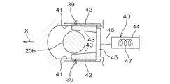
具体的には、図4を参照して、電動モータ20の回転軸20bを挟んで相対向し所定方向Xに沿って延びる互いに平行な一対の受け部41が、例えばステアリングコラム等の固定部材に設けられる。各受け部41と回転軸20bの周面との間に、上記楔状部材からなる摩擦抵抗付与部材39がそれぞれ配置される。
各摩擦抵抗付与部材39と対応する受け部41との間には、何れか一方に設けられる凸条と他方に設けられる凹条とを組み合わせた案内機構42が設けられ、この案内機構42により各摩擦付与部材39の所定方向Xに沿っての進退が案内される。
【0028】
各楔状部材39の回転軸20bへの摺接面43は、互いに逆向きに傾斜されており、これにより、各楔状部材39は所定方向Xに向かうにしたがって先細り状となっている。
駆動部材としてのプランジャ40は、ステアリングコラム等の固定部材に固定される固定部44と、この固定部44から突出してその先端に連結部材45を介して一対の摩擦抵抗付与部材39を固定する可動部46とを備え、ソレノイド47及び図示しない戻しばねを内蔵している。制御部Cは駆動回路48(図3参照)を介してプランジャ40に制御信号を出力する。
【0029】
他の構成については図1の実施の形態と同様であるので、図に同一符号を付してその説明を省略する。
次いで、図5のフローチャートを参照して、本実施の形態において制御部Cにより実行される舵取り制御の処理について説明する。
制御部Cは操舵用アクチュエータ12が正常に動作しているか否かを監視している(ステップT1)。
【0030】
操舵用アクチュエータ12に異常が発生していない場合には(ステップT1でNO)、電磁式のプランジャ40の励磁が解除されている(ステップT2)。このため、図4に示すように可動部45が後退しており、摩擦抵抗付与部材39は回転軸20bから離反している。一方、反力用アクチュエータ20によって、例えば路面反力に応じた操作反力を操舵部材2に与えるためのトルクを発生させる(ステップT3)。
【0031】
また、例えば車両の走行状況等に応じて操舵部材2の回転量と転舵輪9の転舵量との比(伝達比、ギヤ比)を設定し(VGR機能)、この設定した伝達比及び操舵部材2の操作量などに基づいて、操舵用アクチュエータ12の電圧指令値を設定し、その電圧指令値に応じた制御信号を駆動回路31に与えて、操舵用アクチュエータ12を駆動制御する(ステップT4)。
これにより、操舵用アクチュエータ12から、操舵部材2の操作方向に応じた方向に転舵軸7を摺動させるためのトルクが出力され、車両の走行状況や操舵部材2の操作態様に応じた良好な操舵が達成される。なお、必ずしも、VGR機能を設定する必要はない。
【0032】
こうして、操舵アクチュエータ12を駆動制御している間に、操舵アクチュエータ12に異常が発生すると(ステップT1でYES)、制御部Cは、駆動回路32に制御信号を出力し反力用アクチュエータ20をオフする(自由回転可能な状態とする)と共に(ステップT5)、駆動回路48に制御信号を出力し、それまで励磁を解除させていた電磁式のプランジャ40を励磁することで(ステップT6)、楔状部材からなる摩擦抵抗付与部材39を受け部41と回転軸20bとの間に所定方向Xに沿って押し込んで、回転軸20bの周面に摺接面43を摺接させ、摩擦抵抗を付与して回転軸20bの回転を減速させて後、回転軸20bを回転不能に拘束する。
【0033】
これにより、操舵部材2と舵取り機構4との間で、遊星ギヤ機構6を介する機械的な結合が達成され、マニュアルステアリングとして機能させることができる。
図4の実施の形態では楔状部材からなる摩擦抵抗付与部材39を用いたが、これに代えて、図6に示すように、端面49を回転軸20bの周面に押し付けることのできるねじ部材からなる摩擦抵抗付与部材50を用いることもできる。
【0034】
ねじ部材からなる摩擦抵抗付与部材50はその軸心が回転軸20bの径方向に延び、ステアリングコラム等の固定部材に設けられるハウジング51のねじ孔52にねじ込まれている。摩擦抵抗付与部材50の一端にはギヤ53が一体回転可能に連結され、このギヤ53を含む減速機構54を介して摩擦抵抗付与部材50が駆動部材としての電動モータ55により回転駆動され、ねじの軸方向に進退されるようになっている。
【0035】
制御部Cは駆動回路56を介して電動モータ55に制御信号を出力し、操舵用アクチュエータ12の異常発生時に、ねじ部材からなる摩擦抵抗付与部材50の端面49を回転軸20bに摺接させることにより、回転軸20bの回転を減速させた後、回転軸20bを回転不能に拘束する。これにより、マニュアルステアリングとして機能させることができる。
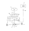
なお、図4や図6の実施の形態においては、電動モータ20の回転軸20bを減速して回転不能に拘束するようにしたが、これに限らず、例えば、図7に示すように、遊星ギヤ機構6Aの第3要素を減速して回転不能に拘束するものであっても良い。
【0036】
図7を参照して、遊星ギヤ機構6Aの第1要素としてのリングギヤ18Aが第1の操舵軸3を介して操舵部材2に連なり、第2要素としての太陽ギヤ15Aが第2の操舵軸5を介して転舵輪9に連なる場合において、遊星ギヤ17Aを支持する第3要素としての例えばキャリア16Aと一体回転する中空軸からなる支軸57を、図4の実施の形態と同様の摩擦抵抗付与部材39及びプランジャ40を用いて減速し回転不能に拘束することができる。なお、図6の実施の形態と同様の摩擦抵抗付与部材50を用いて支軸57を減速し回転不能に拘束するようにしても良い。上記キャリア16Aの中空軸からなる支軸57内には第2の操舵軸5が挿通される。
【0037】
図7の実施の形態においても、図4や図6の実施の形態と同様の効果を奏することができ、加えて、支軸57の回転速度が比較的遅いので、減速させ易いという利点もある。
また、電動モータ20の回転軸20bの回転を減速し、回転不能に拘束するための例として、図8に示すように、摩擦ブレーキ58を用いることもできる。図8を参照して、抑制手段としての摩擦ブレーキ58は、電動モータ20の回転軸20bに一体回転に連結される回転側摩擦板59と、駆動部材としての電磁式のプランジャ60によって進退され、進出位置にて上記回転側摩擦板59に摩擦結合可能な回動不能な固定側摩擦板61とを含む。
【0038】
プランジャ60はステアリングコラム等の固定部材に固定される固定部62と、この固定部62から突出し先端に固定側摩擦板61を固定する可動部63とを備え、ソレノイド64及び図示しない戻しばねを内蔵している。制御部Cは駆動回路65を介してプランジャ60に制御信号を出力する。
図8に実施の形態においても、操舵用アクチュエータ12の異常発生時に、摩擦ブレーキ58によって回転軸20bを減速して後、回転不能に拘束することで、マニュアルステアリングとして機能させることができる。
【0039】
なお、上記の各実施の形態は、車両用操舵装置1がSBWのシステムとして構成され、第2アクチュエータが反力用アクチュエータとして用いられる例について示したが、これに限らず、例えば、第2のアクチュエータとしての電動モータ20を転舵比可変用アクチュエータとして用いるVGRのシステムとして構成されるものであっても良い。この場合、通常時は電動モータ20によりVGR機能を発揮させ、操舵用アクチュエータ12の故障発生時には、転舵比可変用アクチュエータとしての電動モータ20をオフし(自由回転可能な状態にし)、電動モータ20の回転軸20bや支軸57の回転を減速して後、回転不能に拘束して、マニュアル操舵による良好な操舵を達成することができる。
【0040】
また、上記各実施の形態においては、操舵部材2に連なる第1要素、及び転舵輪9に連なる第2要素を、太陽ギヤ15、キャリア16及びリングギヤ18の中から何れか2つを選び、残りのギヤを第3要素として、該第3要素に反力用アクチュエータ20を駆動伝達可能に連結するようにすれば良い。
その他、本発明は上記各実施の形態に限定されるものではなく、例えば、遊星ギヤ機構6に代えて、遊星ローラ機構を用いることが可能である。
【図面の簡単な説明】
【図1】本発明の一実施の形態の車両用操舵装置の概略構成を示す模式図である。
【図2】図1の車両用操舵装置の舵取り制御の流れを示すフローチャートである。
【図3】本発明の別の実施の形態の車両用操舵装置の概略構成を示す模式図である。
【図4】図3の車両用操舵装置の要部の模式的断面図である。
【図5】図3の車両用操舵装置の舵取り制御の流れを示すフローチャートである。
【図6】本発明の別の実施の形態の車両用操舵装置の要部の模式的断面図である。
【図7】本発明のさらに別の実施の形態の車両用操舵装置の概略構成を示す模式図である。
【図8】本発明のさらに別の実施の形態の車両用操舵装置の模式的断面図である。
【符号の説明】
1 車両用操舵装置
2 操舵部材
3 第1操舵軸
4 舵取り機構
5 第2操舵軸
6 遊星ギヤ機構(差動伝達機構)
7 転舵軸
7a ラック
9 転舵輪
12 操舵用アクチュエータ(第1アクチュエータ)
14 ピニオン
15,15A 太陽ギヤ(第1要素)
16,16A キャリア(第2要素)
17,17A 遊星ギヤ(第2要素)
18,18A リングギヤ(第3要素)
18a 内歯
18b 外歯
19 駆動伝達ギヤ
20 電動モータ(反力用アクチュエータ。第2アクチュエータ)
21 電磁ブレーキ(抑制手段。減速手段)
22 ラチェット機構(拘束手段)
23 摩擦体(減速手段)
24 プランジャ(減速手段)
25 固定部
26 可動部
27 ソレノイド
28 ラチェット
29 係止爪
30 プランジャ
C 制御部
31〜34 駆動回路
35 操舵角センサ
36 トルクセンサ
37 転舵角センサ
38 車速センサ
39 摩擦抵抗付与部材(摩擦抵抗付与手段。抑制手段)
40 プランジャ(駆動部材)
43 摺接面
48 駆動回路
49 端面
50 摩擦抵抗付与部材(摩擦抵抗付与手段。抑制手段)
51 ハウジング
52 ねじ孔
55 電動モータ
56 駆動回路
57 支軸
58 摩擦ブレーキ(抑制手段)
59 回転側摩擦板
60 プランジャ
61 固定側摩擦板
65 駆動回路[0001]
BACKGROUND OF THE INVENTION
The present invention relates to a vehicle steering apparatus that steers steered wheels based on an operation of a steering member.
[0002]
[Prior art]
As a turning ratio variable mechanism (VGRS: Variable Gear Ratio System) that makes the turning ratio (turning ratio) of steered wheels variable according to the steering amount of a steering member such as a steering wheel, a planetary gear mechanism and a planetary gear Various vehicle steering devices are provided that include an electric motor for changing a steering ratio that drives, for example, a ring gear of a gear mechanism (see, for example, Patent Document 1).
[0003]
Also, in recent years, a so-called steer-by-wire system (simply SBW) in which a mechanical connection between a steering member such as a steering wheel and a steered wheel is released and a part of a steering transmission system is configured by an electrical path. (Refer to
[0004]
[Patent Document 1]
Japanese Patent Laid-Open No. 5-77751 [Patent Document 2]
Japanese Patent Laid-Open No. 1-233170
[Problems to be solved by the invention]
However, in the above-described VGRS or SBW vehicle steering system, for example, a fail-safe measure against a disconnection or the like in an electric motor as a steering actuator is important.
The present invention has been made in view of the above problems, and an object of the present invention is to provide a vehicle steering apparatus that can achieve good steering even in the event of a failure of a steering actuator in VGRS or SBW.
[0006]
[Means for Solving the Problems and Effects of the Invention]
In order to achieve the above object, the invention according to claim 1 is a differential transmission mechanism including a first element connected to a steering member, a second element connected to a steered wheel, and a third element associating the first and second elements. A first actuator for turning the steered wheels, a second actuator coupled to the third element of the differential transmission mechanism so as to be capable of driving transmission, and drive transmission from the second actuator to the third element , The suppression means that can decelerate and suppress the rotation of the rotation shaft of the second actuator, the restraining means that restrains the rotation of the rotation shaft of the second actuator to be non- rotatable, and when the abnormality occurs in the first actuator, Control means for restraining the rotation of the second actuator by the restraining means after restraining the drive transmission from the second actuator to the third element for a predetermined time by the restraining means. It is characterized in.
[0007]
In the present invention, normally, by generating an appropriate torque to the second actuator, an appropriate steering reaction force is applied to the steering member via the differential transmission mechanism, or the difference is made to change the turning ratio. Drives the third element of the motion transmission mechanism. Further, when an abnormality occurs in the first actuator, by suppressing the drive transmission from the second actuator to the third element of the differential transmission mechanism, the transmission ratio by the remaining two elements of the differential transmission mechanism is reduced. Manual steering can be achieved. Manual steering can be reliably realized even when the second actuator is disconnected or runs away.
[0008]
According to a second aspect of the present invention, in the first aspect, the second actuator includes an electric motor, and the restraining means includes a ratchet that can rotate integrally with a rotating shaft of the electric motor, and a latch that can be locked to the ratchet. a pawl seen including, said suppressing means is characterized in that comprising a decelerating means for mechanically decelerate the rotation of the rotating shaft of the electric motor. In the present invention, when an abnormality occurs in the first actuator, the rotation of the rotating shaft of the electric motor as the second actuator is decelerated by the speed reducer, and the engaging claw is engaged with the ratchet to lock the rotating shaft so that it cannot rotate. The manual steering at the transmission ratio by the remaining two elements of the differential transmission mechanism can be achieved. Since the decelerating means and the locking claw are used in combination, the locking claw is not repelled or damaged by the ratchet, and the rotation shaft can be reliably locked to be non-rotatable by the locking claw.
[0009]
According to a third aspect of the present invention, in the first aspect, the second actuator includes an electric motor, and the suppression means supports the rotation of the rotary shaft of the electric motor or the third element that rotates integrally with the third element. Friction resistance imparting means capable of imparting friction resistance to the rotation of the shaft is included. In the present invention, the same effect as that of the first aspect of the invention can be achieved. Further, even if the rotating shaft is rotating at high speed, the rotation can be decelerated, so that the rotation of the rotating shaft or the like can be reliably suppressed, and manual steering can be reliably achieved when an abnormality occurs in the first actuator. .
[0010]
According to a fourth aspect of the present invention, in the first aspect, the second actuator includes an electric motor, and the suppressing means includes a rotation side friction plate that rotates integrally with a rotation shaft of the electric motor, and the rotation side friction plate. And a non-rotatable fixed friction plate that can be frictionally coupled. In the present invention, the same effect as that of the first aspect of the invention can be achieved. Moreover, even if the rotating shaft is rotating at a high speed, this rotation can be decelerated, so that the rotation of the rotating shaft can be reliably suppressed, and manual steering can be achieved reliably when an abnormality occurs in the first actuator.
[0011]
DETAILED DESCRIPTION OF THE INVENTION
Preferred embodiments of the present invention will be described with reference to the accompanying drawings.
FIG. 1 is a schematic diagram showing a schematic configuration of a vehicle steering apparatus according to an embodiment of the present invention. Referring to FIG. 1, the present steering apparatus 1 is provided with a
[0012]
The
[0013]
A
The planetary gear mechanism 6 includes a
[0014]
The
[0015]
A feature of the present embodiment is that when an abnormality occurs in the
Specifically, the
[0016]
The
The
[0017]
The
[0018]
The
The steering
[0019]
The
The steered shaft 8 is provided with a steered
[0020]
The control unit C is driven by
FIG. 2 is a flowchart for explaining steering control processing executed by the control unit C. Referring to FIG. 2, control unit C monitors whether or not steering
[0021]
If no abnormality has occurred in the steering actuator 12 (NO in step S1), the excitation of the
Further, for example, a ratio (transmission ratio, gear ratio) between the rotation amount of the steering
[0022]
As a result, torque for sliding the steered
Thus, if an abnormality occurs in the
[0023]
After the excitation of the
Thereby, the mechanical coupling via the planetary gear mechanism 6 is achieved between the steering
[0024]
As described above, in the present embodiment, in the normal state, it functions as a steer-by-wire system, an appropriate steering reaction force is applied to the steering
[0025]
Further, since the
Furthermore, even when the
[0026]
As the
Next, FIG. 3 shows another embodiment of the present invention. Referring to FIG. 3, the present embodiment is different from the embodiment of FIG. 1 in that in the embodiment of FIG. 1, the
[0027]
Specifically, referring to FIG. 4, a pair of
Between each frictional
[0028]
The slidable contact surfaces 43 of each wedge-shaped
The
[0029]
Since other configurations are the same as those of the embodiment of FIG. 1, the same reference numerals are given to the drawings, and description thereof is omitted.
Next, steering control processing executed by the control unit C in the present embodiment will be described with reference to the flowchart of FIG.
The controller C monitors whether or not the
[0030]
If no abnormality has occurred in the steering actuator 12 (NO in step T1), the excitation of the
[0031]
Further, for example, a ratio (transmission ratio, gear ratio) between the rotation amount of the steering
As a result, torque for sliding the steered
[0032]
Thus, if an abnormality occurs in the
[0033]
Thereby, the mechanical coupling via the planetary gear mechanism 6 is achieved between the steering
In the embodiment of FIG. 4, the frictional
[0034]
The axial center of the frictional
[0035]
The control unit C outputs a control signal to the
In the embodiment shown in FIGS. 4 and 6, the
[0036]
Referring to FIG. 7, a
[0037]
In the embodiment of FIG. 7, the same effects as those of the embodiment of FIGS. 4 and 6 can be obtained. In addition, since the rotational speed of the
Further, as an example for decelerating the rotation of the
[0038]
The plunger 60 includes a fixed
In the embodiment shown in FIG. 8 as well, when an abnormality occurs in the
[0039]
In each of the above-described embodiments, the vehicle steering apparatus 1 is configured as an SBW system and the second actuator is used as a reaction force actuator. The
[0040]
Further, in each of the above embodiments, any one of the first element connected to the steering
In addition, the present invention is not limited to the above embodiments, and for example, a planetary roller mechanism can be used instead of the planetary gear mechanism 6.
[Brief description of the drawings]
FIG. 1 is a schematic diagram showing a schematic configuration of a vehicle steering apparatus according to an embodiment of the present invention.
2 is a flowchart showing a flow of steering control of the vehicle steering apparatus of FIG. 1; FIG.
FIG. 3 is a schematic diagram showing a schematic configuration of a vehicle steering system according to another embodiment of the present invention.
4 is a schematic cross-sectional view of a main part of the vehicle steering device of FIG. 3;
5 is a flowchart showing a flow of steering control of the vehicle steering apparatus of FIG. 3; FIG.
FIG. 6 is a schematic cross-sectional view of a main part of a vehicle steering system according to another embodiment of the present invention.
FIG. 7 is a schematic diagram showing a schematic configuration of a vehicle steering apparatus according to still another embodiment of the present invention.
FIG. 8 is a schematic cross-sectional view of a vehicle steering apparatus according to still another embodiment of the present invention.
[Explanation of symbols]
DESCRIPTION OF SYMBOLS 1
7
14
16,16A Carrier (second element)
17, 17A Planetary gear (second element)
18, 18A Ring gear (third element)
18a
21 Electromagnetic brake (suppression means, deceleration means)
22 Ratchet mechanism (restraint)
23 Friction body (deceleration means)
24 Plunger (Deceleration means)
25 fixed
40 Plunger (drive member)
43 Sliding
51
59 Rotating side friction plate 60
Claims (4)
転舵輪を転舵させるための第1アクチュエータと、
差動伝達機構の第3要素に駆動伝達可能に連結される第2アクチュエータと、
第2アクチュエータから上記第3要素への駆動伝達を、第2アクチュエータの回転軸の回転を減速させて、抑制することのできる抑制手段と、
第2アクチュエータの回転軸の回転を回転不能に拘束する拘束手段と、
上記第1アクチュエータの異常発生時に、上記抑制手段によって第2アクチュエータから上記第3要素への駆動伝達を所定時間抑制させた後に、拘束手段によって第2アクチュエータの回転を拘束する制御手段とを備えることを特徴とする車両用操舵装置。A differential transmission mechanism including a first element linked to the steering member, a second element linked to the steered wheel, and a third element associating the first and second elements;
A first actuator for turning the steered wheels;
A second actuator coupled to the third element of the differential transmission mechanism so as to be capable of driving transmission;
Suppression means capable of suppressing drive transmission from the second actuator to the third element by decelerating the rotation of the rotation shaft of the second actuator ;
Restraining means for restraining the rotation of the rotation shaft of the second actuator to be non-rotatable ;
Control means for restraining the rotation of the second actuator by the restraining means after restraining the drive transmission from the second actuator to the third element by the restraining means for a predetermined time when the abnormality of the first actuator occurs. A vehicle steering apparatus characterized by the above.
上記拘束手段は、上記電動モータの回転軸に一体回転可能なラチェットとこのラチェットに係止可能な係止爪とを含み、
上記抑制手段は上記電動モータの回転軸の回転を機械的に減速するための減速手段を含むことを特徴とする車両用操舵装置。In Claim 1, the said 2nd actuator contains an electric motor,
The restraining means includes a ratchet that can rotate integrally with the rotating shaft of the electric motor, and a locking claw that can be locked to the ratchet.
The vehicle steering apparatus according to claim 1, wherein the suppression means includes a speed reduction means for mechanically reducing the rotation of the rotation shaft of the electric motor.
上記抑制手段は、上記電動モータの回転軸の回転、又は第3要素に一体回転する第3要素の支軸の回転に摩擦抵抗を与えることのできる摩擦抵抗付与手段を含むことを特徴とする車両用操舵装置。In Claim 1, the said 2nd actuator contains an electric motor,
The suppression means includes a friction resistance applying means capable of giving a friction resistance to the rotation of the rotating shaft of the electric motor or the rotation of the support shaft of the third element that rotates integrally with the third element. Steering device.
上記抑制手段は、上記電動モータの回転軸に一体回転する回転側摩擦板と、この回転側摩擦板に摩擦結合可能な回動不能な固定側摩擦板とを含むことを特徴とする車両用操舵装置。In Claim 1, the said 2nd actuator contains an electric motor,
The restraint means includes a rotation-side friction plate that rotates integrally with a rotation shaft of the electric motor, and a non-rotatable fixed-side friction plate that can be frictionally coupled to the rotation-side friction plate. apparatus.
Priority Applications (1)
| Application Number | Priority Date | Filing Date | Title |
|---|---|---|---|
| JP2002281669A JP4189727B2 (en) | 2002-09-26 | 2002-09-26 | Vehicle steering system |
Applications Claiming Priority (1)
| Application Number | Priority Date | Filing Date | Title |
|---|---|---|---|
| JP2002281669A JP4189727B2 (en) | 2002-09-26 | 2002-09-26 | Vehicle steering system |
Publications (2)
| Publication Number | Publication Date |
|---|---|
| JP2004114857A JP2004114857A (en) | 2004-04-15 |
| JP4189727B2 true JP4189727B2 (en) | 2008-12-03 |
Family
ID=32276056
Family Applications (1)
| Application Number | Title | Priority Date | Filing Date |
|---|---|---|---|
| JP2002281669A Expired - Fee Related JP4189727B2 (en) | 2002-09-26 | 2002-09-26 | Vehicle steering system |
Country Status (1)
| Country | Link |
|---|---|
| JP (1) | JP4189727B2 (en) |
Families Citing this family (6)
| Publication number | Priority date | Publication date | Assignee | Title |
|---|---|---|---|---|
| ES2296178T3 (en) † | 2004-05-10 | 2008-04-16 | Ovalo Gmbh | DEVICE FOR SUPERPOSITION OF STEERING MOVEMENTS FOR AN ASSISTED MANAGEMENT SYSTEM AS WELL AS PROCEDURE FOR THE OPERATION OF THE DEVICE. |
| US7926613B2 (en) * | 2005-09-14 | 2011-04-19 | Toyota Jidosha Kabushiki Kaisha | Steering system for vehicle |
| JP4715688B2 (en) * | 2006-09-15 | 2011-07-06 | トヨタ自動車株式会社 | Variable transmission ratio steering device |
| KR101405630B1 (en) | 2008-04-02 | 2014-06-10 | 현대자동차주식회사 | Variable speed reducer of electric power steering system |
| JP5077785B2 (en) | 2010-08-06 | 2012-11-21 | 株式会社デンソー | Steering control device |
| CN106428204B (en) * | 2016-11-15 | 2018-11-09 | 南京航空航天大学 | A kind of active composite turning system, torque control unit and method for controlling torque |
-
2002
- 2002-09-26 JP JP2002281669A patent/JP4189727B2/en not_active Expired - Fee Related
Also Published As
| Publication number | Publication date |
|---|---|
| JP2004114857A (en) | 2004-04-15 |
Similar Documents
| Publication | Publication Date | Title |
|---|---|---|
| JP4147836B2 (en) | Vehicle steering system | |
| CN105216858B (en) | Steering | |
| JP2528140B2 (en) | Clutch device | |
| JP7052529B2 (en) | Actuator and steer-by-wire steering system | |
| US7789784B2 (en) | Steering device | |
| JP2008030747A (en) | Steering device | |
| KR20130098815A (en) | Reducer of electric power steering apparatus | |
| JP4189727B2 (en) | Vehicle steering system | |
| JP2008189077A (en) | Vehicle steering system | |
| CN101119884A (en) | Steering apparatus | |
| JP4055520B2 (en) | Vehicle steering system | |
| JP4055519B2 (en) | Vehicle steering system | |
| JP2003118597A (en) | Vehicle steering system | |
| JP4055484B2 (en) | Vehicle steering system | |
| JP2000085610A (en) | Vehicle steering control device | |
| JP2008164111A (en) | Electric disc brake | |
| JP2004009989A (en) | Steering device for vehicle | |
| JP4062038B2 (en) | Vehicle steering system | |
| EP3106357A1 (en) | Electronic steering column lock system | |
| JPH0639665U (en) | Electric power steering device | |
| JP4066925B2 (en) | Power steering device with reduction gear | |
| JP4774947B2 (en) | Variable steering angle steering device, automobile, steering system contraction method, and planetary roller mechanism | |
| JP4062020B2 (en) | Vehicle steering system | |
| JP2005081916A (en) | Vehicle steering control device. | |
| JPH05124534A (en) | Steering device for vehicle |
Legal Events
| Date | Code | Title | Description |
|---|---|---|---|
| A621 | Written request for application examination |
Free format text: JAPANESE INTERMEDIATE CODE: A621 Effective date: 20050823 |
|
| A977 | Report on retrieval |
Free format text: JAPANESE INTERMEDIATE CODE: A971007 Effective date: 20070529 |
|
| A131 | Notification of reasons for refusal |
Free format text: JAPANESE INTERMEDIATE CODE: A131 Effective date: 20070605 |
|
| A521 | Written amendment |
Free format text: JAPANESE INTERMEDIATE CODE: A523 Effective date: 20070801 |
|
| A131 | Notification of reasons for refusal |
Free format text: JAPANESE INTERMEDIATE CODE: A131 Effective date: 20080318 |
|
| A521 | Written amendment |
Free format text: JAPANESE INTERMEDIATE CODE: A523 Effective date: 20080514 |
|
| TRDD | Decision of grant or rejection written | ||
| A01 | Written decision to grant a patent or to grant a registration (utility model) |
Free format text: JAPANESE INTERMEDIATE CODE: A01 Effective date: 20080821 |
|
| A01 | Written decision to grant a patent or to grant a registration (utility model) |
Free format text: JAPANESE INTERMEDIATE CODE: A01 |
|
| A61 | First payment of annual fees (during grant procedure) |
Free format text: JAPANESE INTERMEDIATE CODE: A61 Effective date: 20080903 |
|
| FPAY | Renewal fee payment (event date is renewal date of database) |
Free format text: PAYMENT UNTIL: 20110926 Year of fee payment: 3 |
|
| R150 | Certificate of patent or registration of utility model |
Free format text: JAPANESE INTERMEDIATE CODE: R150 |
|
| FPAY | Renewal fee payment (event date is renewal date of database) |
Free format text: PAYMENT UNTIL: 20110926 Year of fee payment: 3 |
|
| FPAY | Renewal fee payment (event date is renewal date of database) |
Free format text: PAYMENT UNTIL: 20120926 Year of fee payment: 4 |
|
| FPAY | Renewal fee payment (event date is renewal date of database) |
Free format text: PAYMENT UNTIL: 20130926 Year of fee payment: 5 |
|
| LAPS | Cancellation because of no payment of annual fees |