JP4187790B2 - Delivery method for drugs packed in drug glass bottles - Google Patents
Delivery method for drugs packed in drug glass bottles Download PDFInfo
- Publication number
- JP4187790B2 JP4187790B2 JP52469597A JP52469597A JP4187790B2 JP 4187790 B2 JP4187790 B2 JP 4187790B2 JP 52469597 A JP52469597 A JP 52469597A JP 52469597 A JP52469597 A JP 52469597A JP 4187790 B2 JP4187790 B2 JP 4187790B2
- Authority
- JP
- Japan
- Prior art keywords
- recess
- proto
- injector
- glass bottle
- assembly
- Prior art date
- Legal status (The legal status is an assumption and is not a legal conclusion. Google has not performed a legal analysis and makes no representation as to the accuracy of the status listed.)
- Expired - Fee Related
Links
Images


Classifications
-
- A—HUMAN NECESSITIES
- A61—MEDICAL OR VETERINARY SCIENCE; HYGIENE
- A61J—CONTAINERS SPECIALLY ADAPTED FOR MEDICAL OR PHARMACEUTICAL PURPOSES; DEVICES OR METHODS SPECIALLY ADAPTED FOR BRINGING PHARMACEUTICAL PRODUCTS INTO PARTICULAR PHYSICAL OR ADMINISTERING FORMS; DEVICES FOR ADMINISTERING FOOD OR MEDICINES ORALLY; BABY COMFORTERS; DEVICES FOR RECEIVING SPITTLE
- A61J1/00—Containers specially adapted for medical or pharmaceutical purposes
- A61J1/14—Details; Accessories therefor
- A61J1/20—Arrangements for transferring or mixing fluids, e.g. from vial to syringe
- A61J1/2096—Combination of a vial and a syringe for transferring or mixing their contents
-
- A—HUMAN NECESSITIES
- A61—MEDICAL OR VETERINARY SCIENCE; HYGIENE
- A61F—FILTERS IMPLANTABLE INTO BLOOD VESSELS; PROSTHESES; DEVICES PROVIDING PATENCY TO, OR PREVENTING COLLAPSING OF, TUBULAR STRUCTURES OF THE BODY, e.g. STENTS; ORTHOPAEDIC, NURSING OR CONTRACEPTIVE DEVICES; FOMENTATION; TREATMENT OR PROTECTION OF EYES OR EARS; BANDAGES, DRESSINGS OR ABSORBENT PADS; FIRST-AID KITS
- A61F13/00—Bandages or dressings; Absorbent pads
- A61F13/02—Adhesive plasters or dressings
- A61F13/0203—Adhesive plasters or dressings having a fluid handling member
-
- A—HUMAN NECESSITIES
- A61—MEDICAL OR VETERINARY SCIENCE; HYGIENE
- A61J—CONTAINERS SPECIALLY ADAPTED FOR MEDICAL OR PHARMACEUTICAL PURPOSES; DEVICES OR METHODS SPECIALLY ADAPTED FOR BRINGING PHARMACEUTICAL PRODUCTS INTO PARTICULAR PHYSICAL OR ADMINISTERING FORMS; DEVICES FOR ADMINISTERING FOOD OR MEDICINES ORALLY; BABY COMFORTERS; DEVICES FOR RECEIVING SPITTLE
- A61J1/00—Containers specially adapted for medical or pharmaceutical purposes
- A61J1/14—Details; Accessories therefor
- A61J1/20—Arrangements for transferring or mixing fluids, e.g. from vial to syringe
- A61J1/2089—Containers or vials which are to be joined to each other in order to mix their contents
-
- A—HUMAN NECESSITIES
- A61—MEDICAL OR VETERINARY SCIENCE; HYGIENE
- A61L—METHODS OR APPARATUS FOR STERILISING MATERIALS OR OBJECTS IN GENERAL; DISINFECTION, STERILISATION OR DEODORISATION OF AIR; CHEMICAL ASPECTS OF BANDAGES, DRESSINGS, ABSORBENT PADS OR SURGICAL ARTICLES; MATERIALS FOR BANDAGES, DRESSINGS, ABSORBENT PADS OR SURGICAL ARTICLES
- A61L15/00—Chemical aspects of, or use of materials for, bandages, dressings or absorbent pads
- A61L15/16—Bandages, dressings or absorbent pads for physiological fluids such as urine or blood, e.g. sanitary towels, tampons
- A61L15/22—Bandages, dressings or absorbent pads for physiological fluids such as urine or blood, e.g. sanitary towels, tampons containing macromolecular materials
- A61L15/225—Mixtures of macromolecular compounds
-
- A—HUMAN NECESSITIES
- A61—MEDICAL OR VETERINARY SCIENCE; HYGIENE
- A61J—CONTAINERS SPECIALLY ADAPTED FOR MEDICAL OR PHARMACEUTICAL PURPOSES; DEVICES OR METHODS SPECIALLY ADAPTED FOR BRINGING PHARMACEUTICAL PRODUCTS INTO PARTICULAR PHYSICAL OR ADMINISTERING FORMS; DEVICES FOR ADMINISTERING FOOD OR MEDICINES ORALLY; BABY COMFORTERS; DEVICES FOR RECEIVING SPITTLE
- A61J1/00—Containers specially adapted for medical or pharmaceutical purposes
- A61J1/05—Containers specially adapted for medical or pharmaceutical purposes for collecting, storing or administering blood, plasma or medical fluids ; Infusion or perfusion containers
- A61J1/10—Bag-type containers
-
- A—HUMAN NECESSITIES
- A61—MEDICAL OR VETERINARY SCIENCE; HYGIENE
- A61J—CONTAINERS SPECIALLY ADAPTED FOR MEDICAL OR PHARMACEUTICAL PURPOSES; DEVICES OR METHODS SPECIALLY ADAPTED FOR BRINGING PHARMACEUTICAL PRODUCTS INTO PARTICULAR PHYSICAL OR ADMINISTERING FORMS; DEVICES FOR ADMINISTERING FOOD OR MEDICINES ORALLY; BABY COMFORTERS; DEVICES FOR RECEIVING SPITTLE
- A61J1/00—Containers specially adapted for medical or pharmaceutical purposes
- A61J1/14—Details; Accessories therefor
- A61J1/1475—Inlet or outlet ports
-
- A—HUMAN NECESSITIES
- A61—MEDICAL OR VETERINARY SCIENCE; HYGIENE
- A61J—CONTAINERS SPECIALLY ADAPTED FOR MEDICAL OR PHARMACEUTICAL PURPOSES; DEVICES OR METHODS SPECIALLY ADAPTED FOR BRINGING PHARMACEUTICAL PRODUCTS INTO PARTICULAR PHYSICAL OR ADMINISTERING FORMS; DEVICES FOR ADMINISTERING FOOD OR MEDICINES ORALLY; BABY COMFORTERS; DEVICES FOR RECEIVING SPITTLE
- A61J1/00—Containers specially adapted for medical or pharmaceutical purposes
- A61J1/14—Details; Accessories therefor
- A61J1/20—Arrangements for transferring or mixing fluids, e.g. from vial to syringe
- A61J1/2003—Accessories used in combination with means for transfer or mixing of fluids, e.g. for activating fluid flow, separating fluids, filtering fluid or venting
- A61J1/2006—Piercing means
- A61J1/201—Piercing means having one piercing end
-
- A—HUMAN NECESSITIES
- A61—MEDICAL OR VETERINARY SCIENCE; HYGIENE
- A61J—CONTAINERS SPECIALLY ADAPTED FOR MEDICAL OR PHARMACEUTICAL PURPOSES; DEVICES OR METHODS SPECIALLY ADAPTED FOR BRINGING PHARMACEUTICAL PRODUCTS INTO PARTICULAR PHYSICAL OR ADMINISTERING FORMS; DEVICES FOR ADMINISTERING FOOD OR MEDICINES ORALLY; BABY COMFORTERS; DEVICES FOR RECEIVING SPITTLE
- A61J1/00—Containers specially adapted for medical or pharmaceutical purposes
- A61J1/14—Details; Accessories therefor
- A61J1/20—Arrangements for transferring or mixing fluids, e.g. from vial to syringe
- A61J1/2003—Accessories used in combination with means for transfer or mixing of fluids, e.g. for activating fluid flow, separating fluids, filtering fluid or venting
- A61J1/2006—Piercing means
- A61J1/2013—Piercing means having two piercing ends
-
- A—HUMAN NECESSITIES
- A61—MEDICAL OR VETERINARY SCIENCE; HYGIENE
- A61J—CONTAINERS SPECIALLY ADAPTED FOR MEDICAL OR PHARMACEUTICAL PURPOSES; DEVICES OR METHODS SPECIALLY ADAPTED FOR BRINGING PHARMACEUTICAL PRODUCTS INTO PARTICULAR PHYSICAL OR ADMINISTERING FORMS; DEVICES FOR ADMINISTERING FOOD OR MEDICINES ORALLY; BABY COMFORTERS; DEVICES FOR RECEIVING SPITTLE
- A61J1/00—Containers specially adapted for medical or pharmaceutical purposes
- A61J1/14—Details; Accessories therefor
- A61J1/20—Arrangements for transferring or mixing fluids, e.g. from vial to syringe
- A61J1/2003—Accessories used in combination with means for transfer or mixing of fluids, e.g. for activating fluid flow, separating fluids, filtering fluid or venting
- A61J1/2048—Connecting means
- A61J1/2051—Connecting means having tap means, e.g. tap means activated by sliding
-
- A—HUMAN NECESSITIES
- A61—MEDICAL OR VETERINARY SCIENCE; HYGIENE
- A61J—CONTAINERS SPECIALLY ADAPTED FOR MEDICAL OR PHARMACEUTICAL PURPOSES; DEVICES OR METHODS SPECIALLY ADAPTED FOR BRINGING PHARMACEUTICAL PRODUCTS INTO PARTICULAR PHYSICAL OR ADMINISTERING FORMS; DEVICES FOR ADMINISTERING FOOD OR MEDICINES ORALLY; BABY COMFORTERS; DEVICES FOR RECEIVING SPITTLE
- A61J1/00—Containers specially adapted for medical or pharmaceutical purposes
- A61J1/14—Details; Accessories therefor
- A61J1/20—Arrangements for transferring or mixing fluids, e.g. from vial to syringe
- A61J1/2003—Accessories used in combination with means for transfer or mixing of fluids, e.g. for activating fluid flow, separating fluids, filtering fluid or venting
- A61J1/2048—Connecting means
- A61J1/2058—Connecting means having multiple connecting ports
-
- A—HUMAN NECESSITIES
- A61—MEDICAL OR VETERINARY SCIENCE; HYGIENE
- A61J—CONTAINERS SPECIALLY ADAPTED FOR MEDICAL OR PHARMACEUTICAL PURPOSES; DEVICES OR METHODS SPECIALLY ADAPTED FOR BRINGING PHARMACEUTICAL PRODUCTS INTO PARTICULAR PHYSICAL OR ADMINISTERING FORMS; DEVICES FOR ADMINISTERING FOOD OR MEDICINES ORALLY; BABY COMFORTERS; DEVICES FOR RECEIVING SPITTLE
- A61J1/00—Containers specially adapted for medical or pharmaceutical purposes
- A61J1/14—Details; Accessories therefor
- A61J1/20—Arrangements for transferring or mixing fluids, e.g. from vial to syringe
- A61J1/2003—Accessories used in combination with means for transfer or mixing of fluids, e.g. for activating fluid flow, separating fluids, filtering fluid or venting
- A61J1/2048—Connecting means
- A61J1/2065—Connecting means having aligning and guiding means
-
- A—HUMAN NECESSITIES
- A61—MEDICAL OR VETERINARY SCIENCE; HYGIENE
- A61J—CONTAINERS SPECIALLY ADAPTED FOR MEDICAL OR PHARMACEUTICAL PURPOSES; DEVICES OR METHODS SPECIALLY ADAPTED FOR BRINGING PHARMACEUTICAL PRODUCTS INTO PARTICULAR PHYSICAL OR ADMINISTERING FORMS; DEVICES FOR ADMINISTERING FOOD OR MEDICINES ORALLY; BABY COMFORTERS; DEVICES FOR RECEIVING SPITTLE
- A61J1/00—Containers specially adapted for medical or pharmaceutical purposes
- A61J1/14—Details; Accessories therefor
- A61J1/20—Arrangements for transferring or mixing fluids, e.g. from vial to syringe
- A61J1/2003—Accessories used in combination with means for transfer or mixing of fluids, e.g. for activating fluid flow, separating fluids, filtering fluid or venting
- A61J1/2079—Filtering means
- A61J1/2086—Filtering means for fluid filtration
Landscapes
- Health & Medical Sciences (AREA)
- Public Health (AREA)
- Veterinary Medicine (AREA)
- Life Sciences & Earth Sciences (AREA)
- Animal Behavior & Ethology (AREA)
- General Health & Medical Sciences (AREA)
- Engineering & Computer Science (AREA)
- Pharmacology & Pharmacy (AREA)
- Vascular Medicine (AREA)
- Heart & Thoracic Surgery (AREA)
- Biomedical Technology (AREA)
- Hematology (AREA)
- Chemical & Material Sciences (AREA)
- Materials Engineering (AREA)
- Epidemiology (AREA)
- Medical Preparation Storing Or Oral Administration Devices (AREA)
- Infusion, Injection, And Reservoir Apparatuses (AREA)
Abstract
Description
本発明は、複合成分の調合薬のための配達方式に関する。
多くの調合薬は、調合薬を投与する直前にのみ組み合わせることができる2またはそれ以上の個別の成分として分配されなければならないが、それは通常、組み合わせられた調合薬は、急速に質の低下を受けやすく、さもなければ、不安定であるからであり、またそれらの成分は、個別に貯蔵されている時にのみ安定している。典型的には、そのような調合薬の少なくとも1成分は、他の成分に対して溶剤、希釈剤または担体として作用する液体である。
従来、蓋でガラス瓶の頸部に固着される可貫通性のエラストマー製止め栓により閉鎖される頸部を持つ従来型の薬剤ガラス瓶に詰められた1成分を使用し、皮下注射器の中の2番目の液体成分を使用し、止め栓を貫通してガラス瓶の中に2番目の液体成分を注入し、注射器を突き刺したガラス瓶を揺らし、1番目の成分を2番目の成分の中に溶解し、希釈しまたは懸濁し、そして組み合わせた成分をプランジャーを引っ込めて吸引することにより、投与する直前にそのような調合薬を調合してきた。この手順は、ある程度の器用さを必要とし、またその手順は、一般的に薬剤を手で現場で調合することに伴う失敗を侵し易く、また殺菌と妥協するかもしれない。3番目の成分を使用するときは、その手順を繰り返さなければならない。
これらの課題を克服するよう努力するに当たって、予め詰められた2成分の薬剤を提供する方式に対して多くの提案が行われてきたが、しかしこれらは、特殊化した充填器具のため、複雑で高価な構造という必要条件、使用時の複雑な操作、またしばしばすべての中で最大のものとして、新しい製品に対する取締上の承認を得るに当たっての所要時間および費用についての重い負担というようなそれらに独特な1またはそれ以上の課題で悩みがちである。
米国特許第3,872,867号(Killinger)は、二重端部のカニューレと協働する管状組立品を利用しており、2本のガラス瓶の中の成分を組み合わせるために、そのカニューレの中にに2本の薬剤ガラス瓶が押し込まれる。この方式は、ガラス瓶のうちの1本が圧力的に真空状態であることが必要であり、そして単に結果として組み合わされた生成物を容れたガラス瓶ができ、その組み合わされた生成物を投与するためには、さらに注射器に移し変えなければならない。
米国特許第3,563,373号(Paulson)は、2成分の薬剤を詰めるため縦に並んだ2個のカートリッジを利用し、二重端部の針と協働する中間組立品を利用し、その二重端部の針が、1個のカートリッジのピストンとその他のカートリッジの頸部止め栓を貫通する実施態様を開示している。その実施態様は、標準的な薬剤ガラス瓶を利用できない。
また、米国特許第4,060,082号(Lindberg)は、注射器に特殊化した補助ピストンと、2成分の薬剤を組み合わせるため縦に並んだ2本の注射器とを必要とする。米国特許第4,583,971号(Bocquet他)は、液体を可撓性のある容器からカニューレを通じて移し変え、薬剤を溶解し、そしてその溶液を可撓性のある容器に戻すための器具を開示している。その方式は、可撓性のある容器を通る確実な閉鎖部の取り扱いに左右され、液体を注射器から薬剤ガラス瓶へ移し変え、そして再度元に戻すように使用することはできない。
米国特許第5,171,214号(Kolber他)は、ガラス瓶組立品と、注射器組立品と、ガラス瓶組立品を注射器組立品に取付けるためのアダプタとを開示し、それにより、液体成分を注射器からガラス瓶へ移し変え、混合済合成物を注射器に戻すことができる。特別のガラス瓶と特別の注射器を必要とし、実際、その方式は、独占的なガラス瓶組立品を使用させられることを意味している。
本発明は、製造が経済的であり、操作が容易であり、かつ取締上の負担が最小にできる2成分の薬剤のための配達方式を提供することを目的とする。
発明の概要
本発明によれば、可貫通性の栓を有するプロト注射器または薬剤ガラス瓶のための活性化組立品が提供され、その活性化組立品は、開口端から延在し前記開口端において可貫通性の栓のあるプロト注射器または薬剤ガラス瓶の少なくとも1部分を受容する第1部分と第1部分からソケットの対向端部まで延在する第2部分とを有する管状ソケットと、ソケットの前記対向端部にある誘導部と、前記誘導部内でソケットの前記第2部分の軸方向に移動するための可動受口組立品で、その1端部においてソケットの中へ延在しその他端部において液体配達導管から延在するカニューラを有する受口組立品と、カニューラを囲む可貫通性の鞘とからなり、その受口及びそのプロト注射器またはその薬剤ガラス瓶が、被覆がカニューラと同軸である領域で可貫通性の栓と接触する位置とカニューラが被覆と栓の両方を貫通する位置との間を、ソケットの中で相対的に移動可能である。
本発明は、多成分の調合薬について個別に予め詰められた成分から充填済注射器を準備するための組立品まで広がるものであり、その組立品は、2部品の管状体と;第1部品において、直径の1端部に第1円筒凹部を画成して、プロト注射器の蓋をされた端部を、摺動取付けで、受容し、その端部において、蓋が、プロト注射器の円筒体の本質的な部分と同様に、プロト注射器の頸部の可貫通性閉鎖体を保持する本体で、そのプロト注射器の円筒体が、調合薬の1番目の液体成分を容れ、円筒体内のピストンで本体内に保持され、それに加えて密封滑動シールを形成する本体と;第2分離可能部品により管状体の他端部に画成され、調合薬の2番目の成分を容れた薬剤ガラス瓶の頸部に可貫通性閉鎖体を固着する蓋を、押付け取付けで、受容する第2円筒凹部と;前記第1部品に円筒凹部と接続する通路を画成する管状体と;通路内で管状体の縦方向に移動可能な受口と;前記受口から反対方向の遠位端まで管状体の縦方向に延在し、前記受口を通って互いに連絡する複数のカニューラと;カニューラの遠位端を被覆し、円筒凹部に挿入されるプロト注射器および薬剤ガラス瓶の可貫通性閉鎖体と接触するように位置する複数の可貫通性被覆部材と;受口組立品と同心で、第1円筒凹部の管状体内に位置する中空円筒オーバーキャップで、受口と接続させられ、通路への受口の移動を制限するオーバーキャップとを具備し;円筒凹部の深さ、凹部と接続する通路の長さ、受口からのカニューラの限度および第1円筒凹部のオーバーキャップの位置選定は、互いに向かって押し込まれる第1円筒凹部に受容されるプロト注射器と第2円筒凹部に受容されるガラス瓶とに依るものであり、オーバーキャップは、プロト注射器の蓋の上に押し込まれ、受口は、縦方向に移動し、それにより、カニューラは、可貫通性密閉部材とプロト注射器およびガラス瓶の可貫通性閉鎖体とをそれぞれともに貫通し、カニューラを通って液体が連絡するようにプロト注射器およびガラス瓶を配置する。
先行する段落ならびにその他この明細書および付随する請求の範囲において、使用される2つの用語については言及する必要がある。「プロト注射器(protosyringe)」は、充填済注射器の基盤を形成することを意図する組立品であるが、完成注射器を形成するためには成分を追加することが必要である。プロト注射器は、最低限、少なくとも調合生成物の成分を容れる円筒本体を含み、その本体は、くびれた1端部に可貫通性の閉鎖体を固着させる蓋で閉鎖され、また反対側端部で活性化用プランジャーと接続するための手段と接続され、またはその手段を備えるピストンで閉鎖される。プロト注射器は、私の米国特許第5,364,369号で説明しているような底のないガラス瓶と;カートリッジと;少なくとも後で規定するようなオーバーキャップの追加と、すぐに使用できる注射器を提供するため調合生成物のさらなる成分の導入とを必要とする充填済注射器とを具備する。「オーバーキャップ(overcap)」は、プロト注射器の蓋の上に取り付けるように適合させられた蓋であり、プロト注射器で形成される注射器の内容物を放出できる針または他の手段を支持するための手段を提供する。ある例では、注射器が、オーバーキャップが受容できる可貫通性材料の蓋で閉鎖されるルアー接続部を有する場合、完成した充填済注射器自体を、プロト注射器として使用することができる。
また、本発明は、協働する円筒凹部と既に係合したプロト注射器および/または薬剤ガラス瓶を持つ組立品の組み合わせまで広がる。プロト注射器が、既に第1円筒凹部と係合しているとき、その自由端は、取り外し可能な蓋で覆うことができ、結果として組立品の時期尚早の活性化が起きる円筒底部の中への不測の突出を防止する。プロト注射器またはガラス瓶が、その円筒凹部と予め係合しているとき、組立品の協働する密閉部材は、それにより、カニューラと同心の区域にあるガラス瓶の可貫通性閉鎖体と弾力的に接触し、カニューラで貫通されることを意図している密閉部材および閉鎖体の区域の無菌を維持することを助ける。
また、受口組立品および変形オーバーキャップは、プロト注射器または薬剤ガラス瓶と連結しで利用されてもよく、プロト注射器またはガラス瓶の中に容れられた調合薬のための別の配達方式を提供する。
本発明のさらなる特徴は、本発明の実施例についての以下の説明で明らかになる。
図面
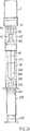
図1は、本発明に基づく組立品の構成要素の分解組立図であり、底のないガラス瓶、この場合においてはプロト注射器と、薬剤ガラス瓶との両方を具備している;
図2は、本発明に基づく組立品を表しており、取り付けられているように底のないガラス瓶を具備している;
図3は、同じ組立品を表しているが、活性化するための準備ができている薬剤ガラス瓶をさらに具備している;
図4は、図3に基づく組立品の構成要素を部分断面図として表しているが、明瞭にするために、上部の構成要素を取り除いている;
図5は、図4と同じ図であるが、組立品の活性化後、完成充填済注射器を準備するために、組立品が呈する関係で表された構成要素を示している;
図6は、活性化後の図3に対応する組立品の図である;
図7は、プランジャーが、液体を底のないガラス瓶から薬剤ガラス瓶へ移し変えるため、上向きに押し込まれた後の組立品の図である;
図8は、混合段階を示す図である;
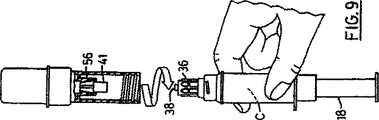
図9は、取り外された組立品の上部部分を示し、針または他の放出手段を適用するために準備ができた注射器がそのまま残されている;
図10は、異なる形状のプロト注射器を利用する配達方式の変更実施例の部分分解組立図である;
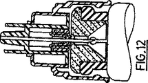
図11および12は、別の形状の注射器ソケットおよび協働する部品についての部分断面図であり、それらの部品により、配達方式の要素を充填済プロト注射器または薬剤ガラス瓶と連絡する配達方式についてのさらなる実施例に使用することができる;
図13は、蓋を断面で示しており、その蓋を図11および12の実施例の受口部分のルアーに適用することができ、受口が、図11の位置から図12の位置まで押し込まれ、充填済注射器を活性化する;
図14は、標準的な可撓性のある小形の袋と連結して使用するための注射器またはガラス瓶を活性化するために、図11および12の実施例で使用する別の活性化方式の部品を分解組立図としてを示す;
図15は、活性化するための準備ができた組立てられた注射器を示す;
図16は、小形の袋に適用される活性化した注射器を示す;
図17は、図1ないし9の実施例についての現在の好ましい変更実施例の構成要素を表す分解組立図である;
図18は、プランジャーを除き、使用できるように組み立てられた図17に示す部品を示す;
図19および20は、図11および12の実施例の現在の好ましい変更実施例を示す;
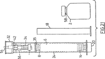
図21は、本発明に基づく組立品のさらなる実施例の組立られた構成要素を表す;
図22は、図21の実施例で使用される受口組立品の構成要素の分解組立図である;
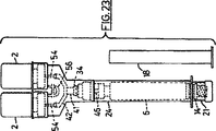
図23は、図18の実施例の変更実施例を示し、本発明の組立品がどのように2成分より多い成分を持つ薬剤を活性化するために使用できるかを示している;図24は、本発明のさらなる実施例に基づく組立品を示す;
図25は、図17および18の実施例に基づく組立品の準備を表す工程系統図である。
好ましい実施例の説明
先ず、図1ないし3を説明すると、それらの部品は、調合薬を容れる注射器を準備するための組立品を示しており、その調合薬の成分AおよびBは、薬剤ガラス瓶2と、円筒体6からなる底のないガラス瓶4の形状をしたプロト注射器とにそれぞれ容れられ、その円筒体6は、1端が開放し、他端に頸部8を設けられ、その頸部が、頸部をかしめる金属製の蓋12により適所に固着されるエラストマー製閉鎖体10により閉鎖される。ピストン14は、その本体の開口端に収容され、そのピストンは、手段16を設けられ、その手段16により分離可能なプランジャー18をピストンに固着することができる。そのプランジャーは、普通は、組立品の全長を縮小することと、組立の不注意に基づく時期尚早の活性化を防止するため、図2に示すように取り外し可能な蓋20を底のないガラス瓶4の突出端に適用可能にすることとの両方のために、ピストンから分離して収容される。成分AおよびBの少なくとも1つは、液体であり;通常、その液体成分を底のないガラス瓶に配置することが便利であるが、しかしまた、固体成分が、ガラス瓶2の液体内容物と置換するのに充分な空気またはガスの量を含むように準備されるとすれば、固体成分を底のないガラス瓶に配置することも可能である。
注射器を介して投与するための代表的な2つの成分の調合薬は、活性のある成分と、液体である溶剤、希釈剤または担体(以後、本明細書においては、便宜上一纏めに希釈剤と呼ぶこととする)とからなり、多くの場合、その希釈剤は、2、3の異なる種類のうちのただ1種類(ほとんど通常、蒸留水)であるので、通常、ガラス瓶2に活性のある成分を配置することが都合がよい;その理由は、まれにそうでない場合もあるが、多くの場合、活性のある成分を適当なガラス瓶に詰めたものが、既に取締当局によって認定されているか、または少なくともそのように認定されることが必要であり、一方、希釈剤を容れたプロト注射器の認定は、希釈剤が従来からあるもであり、且つプロト注射器の構造自体が既に認定されていれば、一般に簡単であるからである。移し替え組立品は、一般的であり、個別に認定されることができる;したがって、調合薬を充填された注射器に転用するための調合薬の成分と組立品の組合わせは、まれに、その組合わせの認定が必要ならば、個別に認定された構成要素で組立てることができる。
組立品の主要部分は、2つの構成要素、すなわちガラス瓶連結体22および注射器ソケット24で形成される管状体を有する。注射器ソケット24は、1端部に外部にねじが切られた端部26を備え、その端部は、ガラス瓶連結体22の隣接端で内部ねじ28にねじ留めされる。ガラス瓶連結体は、円筒凹部30を提供し、ガラス瓶2の蓋をされた端部を受容し、その蓋をされた端部が挿入される程度は、肩部32によって制限される。注射器ソケット24は、円筒凹部31を提供し、その凹部31の中へ底のないガラス瓶4の本体6を摺動させることができるが、当初は、凹部の深さから可能な範囲一杯までは摺動させない。
注射器ソケットの端部26は、注射器または他の液体薬剤の供給源に対する受口34の縦移動のための誘導部52を具備し、その受口34は、連結針産業で利用されるような標準的なルアー(luer)を通る液体配達導管、または液体配達導管拡張部を形成する他の配達手段を前端部に形成される。そのようなルアーは、針を適所に固定するため、内部にねじが切られたソケット36と、相補的なソケットを持つシールを針に設置するためのテーパ付き中央差し込み部38とからなる。この場合、中空の移し替え用針40は、中央差し込み部に収容されるソケット41を備えるが、ねじは設けられず、ソケット36のねじと係合し、それで、針40を、差し込み部38から引き抜くことができる。テーパ付き肩部42が、移し替え用針40に形成される。受口34は、差し込み部38の反対側の端部から突出する中空の針すなわちカニューレ44を有し、差し込み部の中央通路と連絡する。薄いゴム製の可撓性のある針の鞘すなわち被覆46は、受口34の端部でソケットと係合する部分48と針の自由端を覆う平らな端部50とを有し、針44を被覆する。注射器ソケットの誘導部52と端部26との内部は、必要な大きさにされた円筒凹部31の拡張部を包含し、底のないガラス瓶4の蓋12を上手に入れる収納スペースであるオーバーキャップを提供する。
ガラス瓶連結体22は、凹部30から延在する通路を有し、その凹部30は、ガラス瓶2をその内部にねじが切られた端部で受容し、その通路は、ゴムの止め栓すなわち被覆54で閉鎖される。ゴムの止め栓とガラス瓶連結体22の内部にねじが切られた端部との間に、通路が、内部に弾力のある爪56を持って形成され、その爪56は、針が爪を通り過ぎるように押されるとき、針40の肩部42を留置する。
今説明している組立品は、無菌を維持するために取り外し可能な被覆(図示せず)が、連結部22の円筒凹部を覆うため必要とされる場合に、設置されるガラス瓶でも、または設置される1または両方のガラス瓶(図2および3参照)でもなく、組立品自体に取り付ければよい。ガラス瓶2を設置するとき、ガラス瓶の可貫通性閉鎖体58を被覆する蓋60の取り外し可能な中央部分は、はじき飛ばされ、したがって、可貫通性閉鎖体は、止め栓54のリブ64と接触し、2つのゴム部品58および54の軸方向無菌領域を封じ込める。同様に、同じく露出さる閉鎖体10の軸方向領域は、針の鞘46の端部50と接触し、接触するゴム部品に保護領域を提供する。
組立品を活性化するため、図3に示す実施態様を提供するように、ガラス瓶を設置した後、底のないガラス瓶を、注射器のソケット24の中に押し込み、プランジャー18を、取り付け、図6に示すような状態に到達する。
その後、組立品を反転し、プランジャー18を作動し、液体内容物Bを底のないガラス瓶から、薬剤ガラス瓶の中へ放出し(図7参照)、次に組立品を図8に示すように流動させ、液体の中でガラス瓶2の内容物を溶解し、混合し、または懸濁し、そしてその内容物を、プランジャーを引っ込めることにより底のないガラス瓶の中に吸引し、今や、成分Aが成分Bの中に混合され、底のないガラス瓶に生成物Cが残される以外は、図6の状態と同じ状態に到達する。さて、ガラス瓶連結体22を、注射器ソケットからねじを緩めてはずして引き出し、爪56で差し込み部38から外された移し替え針40をそれとともに取り除き、かくして、針または、他の液体接続手段を受容している受口34のルアーを残したままで、2つの成分の調合薬を充填(図9参照)した完成したすぐに使用できる注射器が提供される。受口34は、本体6とルアー36、38との間の通路を提供する針とともに、注射器ソケット24で底のないガラス瓶の蓋12に保持される。
液体および固体の成分の当初の位置が逆転されるときは、ガラス瓶4からガラス瓶2へ空気またはガスを、かつガラス瓶2からガラス瓶4へ液体を強制的に動かすために使用する注射器のプランジャーの往復運動で、反転することなしに図7の段階を行なうことができる。
上述の組立品についての現在の好ましい変更実施例が、図17および18に示されており、それらの図では、同じ参照番号が同様な部品を表すために使用され、異なるもののみが、説明されている。この変更実施例では、受口34の突縁部35が延伸して、オーバーキャップを形成し、注射器の活性化の間中、注射器の本体6が、オーバーキャップに向かって前方に、かつその中に強制的に押しやられると、注射器ソケット24の部分26が、このオーバーキャップの前部を受容するように作用する。図25でよく分かるように、この再配列は、組立を容易にする。蓋20は、駆動装置21に取替えられ、その駆動装置は、それがプロト注射器の後部を被覆する位置で、図18に示すように、注射器ソケット24の開口部をぴったり閉め、その位置から駆動装置21を、組立品が活性化するように前方に押し込むことができる。駆動装置21は、底部開口部を有し、プランジャー18のために便宜をはかる。止め栓54は、被覆46と同様な可撓性のある鞘54に取替えられるが、その理由は、これにより組立品が簡素化され、針40の完全な被覆が提供されると思われるからである。
いろいろな変更実施例が、本発明の範囲内で可能であり、上述の説明は、現在の好ましい実施例についての説明である。例えば、針40を、受口34に永続的に固着させることができるし、また、ガラス瓶の爪を省略することもできる。仕上がった注射器に使用された針を任意に選択をするような実施態様を使用者に提供することはできないし、また針の長さは、ガラス瓶に対する針の長さの範囲を超過することを回避する必要から個別に制約されるべきであり、そのことは、その内容物を吸引することを困難にするからである。
なおその上、底のないガラス瓶4をカートリッジのような他の形式のプロト注射器と取替えてもよいし、あるいばルアー接続を被覆するエラストマー製の閉鎖体を設けた充填済注射器と取り替えてもよく、その注射器の前端部は、針の接続部などを提供し受口を保持する作用もするオーバーキャップを受け入れる。その様な実施態様は、図10に例示されており、その図10は、プロト注射器と取り替えられた底のないガラス瓶を示しており、そのプロト注射器は、注射器本体の前端部を覆う保護用ゴム密閉蓋100により保護されている従来型のルアーノズル101を有する従来型の充填済注射器であり、また注射器ソケット24は、注射器本体6を受容する形状に変形され、注射器本体を把持するため、縦方向の内部リブ102を有する。前述のように、蓋20は、活性化を必要とされるまで、注射器の本体が、注射器ソケット24の中へ完全にに押し込まれることを防止し、また被覆46の端部50は、蓋100に対して当接し、針44で貫通される領域の無菌を維持することを助ける。
もっとさらなる形状のプロト注射器が、使用されてもよい。例えば、公知の形状の希釈液ガラス瓶は、両端にピストンを持つガラス管の形状をした本体6からなる。1端にあるピストンは、拡張部16と同じ拡張部を持つピストン14と同様のものである。他端にあるピストンは、図1に示す底のないガラス瓶の頸部8と、止め栓10と、蓋12との機能を果たす。従来の使用では、ガラス瓶のこの他端部は、スリーブの開口端部に挿入され、そのスリーブは、その他端部において外側でルアーまたは針を、内側で突出する軸方向の中空ピンを支持する。ガラス瓶の他端にあるピストンは、ピストンおよびピストンの外側拡張部を通る軸方向通路を有し、外端が栓により閉鎖され、その栓は、ガラス瓶をスリーブの中へ挿入する時、中空ピンで置換され、かくして針またはルアーとガラス瓶の内部との間の連絡が達成される。ガラス瓶から注射器へのプロト注射は、第1端部で、プランジャーをピストンに使用することにより完成される。本発明においては、この形式のプロト注射器を、図1または図17に示すプロト注射器の代わりに用いることができる。活性化の間中、オーバーキャップ16または35は、ガラス瓶の前記外端でピストンの拡張部の中へ押し込まれる。それにより針44は、鞘46を貫通し、栓と置換する。その栓は、針44によって貫通されるピストンの通路の一体的な隔壁と置換されてもよい。
注射器ソケット自体は、オーバーキャップを除き、完成注射器から分離可能に作られ、あるいは、図11および12に示すように長さが切詰められてもよい。注射器ソケット24が短縮され、直径を縮られて、底のないガラス瓶の蓋を受容し、注射器ソケットが蓋12を上から押し下げ、注射器本体6の肩部と係合することが分かる。
注射器の活性化に当たって、受口34は、ソケット24の端部26に関して下向きに、図11に示す位置から図12に示す位置まで押し込まれる。図11に示す位置おいて、ゴム被覆46の端部50は、保護される接触ゾーンを提供するように、閉鎖体10に対して当接し、その端部50は、受口34の底部の突縁部35が閉鎖体10と接触するまで、受口が誘導部52を通って下向きに押し込まれるにつれて、受口34の針44で貫通される。この時点において、針44は、プロト注射器の本体6の内部との連絡を達成する。
図21は、図11および12(または、後で論じる図19および20)の実施態様が、どのように、組立品がガラス瓶2の挿入により活性化される実施態様に使用されるかを示している。図22で分かるように、カニューラ40の可貫通性被覆54およびカニューラ40自体が、ガラス瓶ソケット32の中に突出するように、構成要素42が延伸され、変形される。ガラス瓶2を挿入するに当たって、被覆54が、構成要素42の凹部に押し入れられ、それにより、被覆54は、カニューラ40で貫通され、また、カニューラ40は、ガラス瓶2の閉鎖体を貫通し、そのガラス瓶の閉鎖体は、構成要素42を圧迫し、それにより、カニューラ44をそのカニューラの鞘または被覆およびプロト注射器の可貫通性閉鎖体を通って押し込む。図19および20の変更態様が図22に示す変形された受口34とともに使用されると、それにより、突縁部35がオーバーキャップを提供し、この押し込み作用は、またプロト注射器の蓋の上ににオーバーキャップ35を押し込む。図11および12の実施態様が使用されるときは、プロト注射器の蓋は、以前にオーバーキヤップに収容されている。
図13は、受口34を押し込む別の手段を表している。受口34のルアー栓38は、図13の断面図で示すように従来型の鋳造被覆体104で被覆され、その被覆体104は、ソケット36にねじ留めされ、受口に対して従来型の駆動装置を提供し、その被覆体は、針を受口のルアーに取付けるのに先立ってねじを外し、捨てられる。。
図14および15は、別の駆動装置の実施態様を表しており、それは、注射器を結合するために使用される公知の形式のアダプタを可撓性のある小型の袋に使用し、それにより注射器の内容物を袋の中に放出し、そして袋の内容物と混合することができる。アダプタ106は、注射器ソケット24の部分26にこの場合一時的に外部ねじ溝でねじ留めするために、1端で内部にねじが切られたソケット118と、他端にあり、袋の接管(nipple)の突出部と係合し、それによりその接管が、受口34の栓38に取り付けられる針112と同心で一直線に並ぶアダプタの中に誘導される溝穴110とを有する管108からなる。蓋114は、管108の溝穴のある端部を覆い、針112の鞘となる同心の内部管状延伸部116を有し、受口が、図11に示す位置にある時、蓋114の中にある距離だけ延伸させられる管108で、受口34のソケット36を延伸する。蓋をさらに押すと、受口34が、図11に示す位置から図12に示す位置へと強制的に押しやられ、かくして、注射器は活性化する。次に、蓋114が、取り除かれ、注射器は、図16に示すように、小型の袋をあてがわれる。代案として、また、管10が取除かれ、すぐに使用できる注射器が提供される。
底のないガラス瓶の形状をしたプロト注射器の代わりに、また図11、12、14および15の実施態様を、標準的薬剤ガラス瓶を活性化するために、使用してもよく、それにより、その内容物は、小型の袋または、他の可撓性のある袋の内容物と混合することができる。可撓性のある袋からの液体は、針を通って活性化されたガラス瓶に入れることができ、次に、ガラス瓶の混合された内容物を、袋と取り付けられた活性化したガラス瓶との適当な操作によって、針を通って袋の中へ戻すことができる。
また、図11および12に示す実施態様は、受口34の突縁部35を延伸して、図19および20に示すように変形し、オーバーキャップ(また、図22参照)を形成することができる。オーバーキャップの下向きの移動に便宜を払い、一方、プロト注射器の内向きの移動を防止するため、注射器ソケットの直径減少部分は、27にあるように下向きに延在させ、プロト注射器の挿入を制限する肩部を形成する。
図23は、3つの成分の薬剤の調合ができるような図17および18の実施例の変更実施例を示している。ガラス瓶ソケット22は、2つのガラス瓶ソケット30および2つの針を提供するために、構成要素42として二股に分けられ、また2本の針は、鞘54によって被覆されているので見えない。駆動装置21を注射器ソケットの中へ押し込んで組立品を活性化させると、ガラス瓶の閉鎖体は、同時に貫通され、液体がプロト注射器本体6から両方のガラス瓶2に入り、それらの内容物を溶解し、懸濁する。活性化にあたって、掛け金部材56が、構成要素42と係合し、前述の実施例のように、それを維持する。
さらなるガラス瓶ソケット30および構成要素42のさらなる枝管を、各追加成分を取り扱うために設けることができる。
さて、図24を説明すると、本発明の原理は、シェルガラス瓶(または示すように、米国第5,364,369A号で説明されているように、底のないガラス瓶206を逆転させ、駆動装置蓋220をその蓋をする端部に利用することによって生じる機能的に同一なシェルガラス瓶)の形状をしたプロト注射器痢用することができる。そのようなシェルガラス瓶は、通常、ピストン214のねじが切られた拡張部216をプランジャー軸の自由端にねじ留めすることによって、プランジャーの他端に接続される同心の注射器シェルの中で、完成注射器として形成される。2重端の針は、プランジャー軸の軸方向で且つプランジャーの他端の外方に延在する。延伸部216を充分にプランジャー軸にねじ留めすることにより、針がピストンを貫通し、それにより、ガラス瓶をプランジャー軸の方へ押し込むことにより、シェルガラス瓶の内容物をその針を通って放出させることができる。そのような実施態様は、すでに上記で参照した米国第5,171,214A号で説明されている。この例では、注射器ソケット224はシェルを提供し、また図1〜10で利用され、図17および18に示すように変形された受口組立品は、細長いカニューラ244を設けられることにより、さらに変形され、その細長いカニューラは、突縁部245を通り抜けてオーバキャップ35に入ることによりカニューラの上に配置される同心のプランジャー軸218で囲まれる。カニューラ224の長さは、構成要素が図24に示す非活性化状態で、ピストン延伸部216がプランジャー軸218の底部でねじが切られたソケットにねじ留めされている状態のピストン21内で可貫通性の栓(図示せず)を除いて、終わるようにする。
組立品は、シェルガラス瓶を上向きに押し込むことにより、軸228の直径減少部分219がオーバキャップ35に入り、カニューラ244がピストンの栓を貫通できるので活性化させられる。さらに上向きに移動すると、カニューラが、受口の上端部で支持され、鞘64およびガラス瓶2の可貫通性の閉鎖体を貫通するようになり、その後、シェルガラス瓶206を従来型のプランジャーの代わりに操作すること除けば、活性化は前に説明したように進行することができる。
さて、図25を説明すると、そこには本発明、詳しくは図17および18の実施例にに基づく組立品の準備についての工程系統図が示されている。
上段左側から始まり、部品34、35、42、46および64を組立て、受口組立品300を形成し、次にその受口300をガンマー放射線により殺菌する(段階320)。無菌室314(上段右側)の中で、部品6、12、14、16を組立て、オーバーキャップ35を利用する蓋にプロト注射器と提供して塞ぐが、しかしオーバーキャップ35内のカニューラにとって被覆または鞘を貫通するのは大いに不充分であるが、サブ組立品306を準備し、次にそのサブ組立品306を、検査所316を通り抜けさせる。
同時に、部品21、22および24を組立て、サブ組立品302を準備し、プランジャー18とともに322でガンマ放射線により殺菌する。プロト注射器と受口組立品との組立品306を、層流で覆って組立品302に挿入し、組立品308を準備する。その後、同じ環境で、蓋の上の保護金属ディスクがはじき飛ばされたガラス瓶2を、組立品308のガラス瓶ソケットに挿入し、その組立品は、図18の組立品と正確に対応する。ガラス瓶2の可貫通性閉鎖体58(図1参照)と被覆64の面50との接触面は、この段階の間に、高強度紫外線の閃光または無菌の噴霧318で殺菌され、その後、プランジャーと一緒になった結果できた組立品310は、プラスチックのトレイ312の中に密閉される。そのトレイは、組立品310の輪郭に対応して形づくられた凹部を持って形成された真空である。詳しくいうと、衝撃または手荒い取扱で使用前におきる可能性のある不注意に基づく活性化を回避するために、この凹部が、作動装置21の狭い部分をぴったり取り囲むことは、都合がよいものである。
勿論、この手順について変更することは可能である。例えば、ガラス瓶に似たプロト注射器を、予め作ってもよいし、また定期的に殺菌してもよいし、また受口組立品を組立て、同様の手段で組立品306を作り、組立品302と308とを組み合わせてもよい。The present invention relates to a delivery system for complex component formulations.
Many pharmaceuticals must be distributed as two or more separate components that can only be combined just prior to administration of the pharmaceutical, although it is usually the case that combined pharmaceuticals rapidly degrade in quality. It is easy to receive, otherwise unstable, and their components are only stable when stored separately. Typically, at least one component of such a formulation is a liquid that acts as a solvent, diluent or carrier relative to the other components.
Conventionally, the second in a hypodermic syringe using one component packed in a conventional pharmaceutical glass bottle with a neck closed by a penetrable elastomeric stopper that is secured to the neck of the glass bottle with a lid Inject the second liquid component into the glass bottle through the stopper, shake the glass bottle that pierced the syringe, dissolve the first component in the second component, and dilute Such formulations have been formulated just prior to administration by suspending and suspending and aspirating the combined components withdrawing the plunger. This procedure requires a certain amount of dexterity, and the procedure is generally susceptible to failure associated with manually dispensing drugs on-site and may compromise sterilization. When using the third component, the procedure must be repeated.
In an effort to overcome these challenges, many proposals have been made for methods to provide pre-packed two-component drugs, but these are complicated due to specialized filling devices. Unique to them, such as the requirement of expensive construction, complex operation during use, and often the largest of all, the heavy burden of time and cost to obtain regulatory approval for a new product Tend to worry about one or more issues.
US Pat. No. 3,872,867 (Killinger) utilizes a tubular assembly that cooperates with a double-ended cannula, two in the cannula to combine the components in the two glass bottles. The drug glass bottle is pushed in. This method requires that one of the glass bottles is pressure-vacuum and simply results in a glass bottle containing the combined product and for administering the combined product. In addition, it must be transferred to a syringe.
U.S. Pat. No. 3,563,373 (Paulson) uses two cartridges arranged vertically to pack a two-component drug, uses an intermediate assembly that cooperates with a double-ended needle, and its double-ended An embodiment is disclosed in which a portion of the needle penetrates the piston of one cartridge and the neck stop of another cartridge. That embodiment cannot utilize standard drug glass bottles.
U.S. Pat. No. 4,060,082 (Lindberg) also requires an auxiliary piston specialized for syringes and two syringes arranged vertically to combine the two components. U.S. Pat. No. 4,583,971 (Bocquet et al.) Discloses a device for transferring liquid from a flexible container through a cannula, dissolving the drug, and returning the solution to the flexible container. . The scheme relies on secure closure handling through the flexible container and cannot be used to transfer liquid from the syringe to the drug vial and back again.
US Pat. No. 5,171,214 (Kolber et al.) Discloses a glass bottle assembly, a syringe assembly, and an adapter for attaching the glass bottle assembly to the syringe assembly, thereby transferring liquid components from the syringe to the glass bottle. The mixed composition can be returned to the syringe. It requires special glass bottles and special syringes, and in fact the scheme means that an exclusive glass bottle assembly can be used.
It is an object of the present invention to provide a delivery system for a two-component drug that is economical to manufacture, is easy to operate, and can minimize the burden on enforcement.
Summary of the Invention
In accordance with the present invention, an activation assembly for a proto-injector or drug glass bottle having a penetrable stopper is provided, the activation assembly extending from the open end and penetrable at the open end. A tubular socket having a first portion for receiving at least a portion of a plugged proto-injector or drug vial and a second portion extending from the first portion to the opposite end of the socket; and at the opposite end of the socket A guide and a movable receptacle assembly for axial movement of the second part of the socket within the guide, extending into the socket at one end and extending from the liquid delivery conduit at the other end; A receptacle assembly having an existing cannula and a penetrable sheath surrounding the cannula, wherein the receptacle and its proto-injector or its drug vial are coaxial with the cannula. In the position and cannula in contact with soluble penetration plug between a position for through both coatings and stoppers, relatively movable in the socket.
The present invention extends from individually pre-packed components to an assembly for preparing a prefilled syringe for a multi-component formulation, the assembly comprising a two-part tubular body; , Defining a first cylindrical recess at one end of the diameter and receiving the capped end of the proto-injector in a sliding attachment, at which end the lid is of the cylindrical body of the proto-injector Similar to the essential part, the body that holds the penetrable closure of the neck of the proto-injector, the cylinder of the proto-injector containing the first liquid component of the drug product, and the body with the piston in the cylinder A body that is held within and additionally forms a hermetic sliding seal; and is defined at the other end of the tubular body by a second separable part and on the neck of the drug glass bottle containing the second component of the drug product The lid that secures the penetrable closure can be received by pressing. A second cylindrical recess comprising: a tubular body defining a passage connected to the cylindrical recess in the first part; a receptacle movable in the longitudinal direction of the tubular body within the passage; A plurality of cannulas extending in the longitudinal direction of the tubular body to the distal end and communicating with each other through said receptacle; a proto-injector and a drug glass bottle penetrating the distal end of the cannula and inserted into the cylindrical recess A plurality of penetrable covering members positioned to contact the permeable closure; concentric with the receiving assembly and connected to the receiving port with a hollow cylindrical overcap positioned within the tubular body of the first cylindrical recess; An overcap for restricting movement of the receiving port into the passage; depth of the cylindrical recess, length of the passage connected to the recess, limit of the cannula from the receiving port, and position selection of the overcap of the first cylindrical recess Are pushed towards each other Depending on the proto-injector received in the first cylindrical recess and the glass bottle received in the second cylindrical recess, the overcap is pushed over the lid of the proto-injector and the receptacle moves longitudinally. The cannula then places the proto-injector and the glass bottle through the pierceable sealing member and the pierceable closure of the proto-injector and the glass bottle, respectively, so that the liquid is in communication through the cannula.
In the preceding paragraph, as well as elsewhere in this specification and the appended claims, the two terms used should be referred to. A “protosyringe” is an assembly intended to form the base of a prefilled syringe, but additional components are required to form a finished syringe. The proto-injector comprises at least a cylindrical body that contains at least the components of the formulation product, the body being closed with a lid that secures a pierceable closure at one constricted end and at the opposite end. Connected to the means for connecting with the activation plunger or closed with a piston comprising the means. The proto-injector was formulated to provide a ready-to-use syringe with a bottomless glass bottle as described in my US Pat. No. 5,364,369; a cartridge; and an overcap as defined at least later A prefilled syringe that requires the introduction of additional components of the product. An “overcap” is a lid adapted to be mounted over a proto-injector lid, for supporting a needle or other means capable of releasing the contents of the syringe formed by the proto-injector. Provide a means. In one example, if the syringe has a luer connection that is closed with a lid of penetrable material that the overcap can accept, the completed prefilled syringe itself can be used as a proto-injector.
The invention also extends to assembly combinations with proto-injectors and / or drug glass bottles already engaged with cooperating cylindrical recesses. When the proto-injector is already engaged with the first cylindrical recess, its free end can be covered with a removable lid, resulting in a cylinder bottom into which premature activation of the assembly occurs. Prevent unexpected protrusion. When the proto syringe or glass bottle is pre-engaged with its cylindrical recess, the cooperating sealing member of the assembly is thereby resiliently in contact with the penetrable closure of the glass bottle in a concentric area with the cannula. And helps maintain the sterility of the sealing member and the area of the closure intended to be penetrated by the cannula.
The receptacle assembly and deformation overcap may also be utilized in conjunction with a proto-injector or drug vial, providing an alternative delivery system for the drug contained in the proto-injector or vial.
Further features of the present invention will become apparent from the following description of embodiments of the present invention.
Drawing
FIG. 1 is an exploded view of the components of an assembly according to the present invention comprising a glass bottle without a bottom, in this case a proto-injector and a drug glass bottle;
FIG. 2 represents an assembly according to the invention, comprising a glass bottle without a bottom as attached;
Figure 3 represents the same assembly, but further comprises a drug glass bottle ready for activation;
FIG. 4 shows the components of the assembly according to FIG. 3 as a partial cross-sectional view, with the upper components removed for clarity;
FIG. 5 is the same view as FIG. 4 but shows the components represented in the relationship that the assembly exhibits in order to prepare the completed filled syringe after activation of the assembly;
6 is a view of the assembly corresponding to FIG. 3 after activation;
FIG. 7 is a view of the assembly after the plunger has been pushed upward to transfer the liquid from the bottomless glass bottle to the drug glass bottle;
FIG. 8 shows the mixing stage;
FIG. 9 shows the upper part of the removed assembly, leaving the syringe ready to apply a needle or other discharge means;
FIG. 10 is a partially exploded view of a modified embodiment of a delivery scheme that utilizes differently shaped proto-injectors;
FIGS. 11 and 12 are partial cross-sectional views of alternative shaped syringe sockets and cooperating parts that further communicate the elements of the delivery system with the prefilled proto-syringe or drug glass bottle. Can be used in the examples;
FIG. 13 shows the lid in cross section, which lid can be applied to the lure of the receptacle part of the embodiment of FIGS. 11 and 12, and the receptacle is pushed from the position of FIG. 11 to the position of FIG. Activates the filled syringe;
FIG. 14 shows another activation system component used in the embodiment of FIGS. 11 and 12 to activate a syringe or glass bottle for use in conjunction with a standard flexible small bag. As an exploded view;
FIG. 15 shows the assembled syringe ready for activation;
Figure 16 shows an activated syringe applied to a small bag;
FIG. 17 is an exploded view showing the components of the presently preferred modified embodiment for the embodiment of FIGS. 1-9;
FIG. 18 shows the parts shown in FIG. 17 assembled for use except for the plunger;
Figures 19 and 20 show a presently preferred modified embodiment of the embodiment of Figures 11 and 12;
FIG. 21 represents the assembled components of a further embodiment of an assembly according to the invention;
22 is an exploded view of the components of the receptacle assembly used in the embodiment of FIG. 21;
FIG. 23 shows a variation of the embodiment of FIG. 18 and shows how the assembly of the present invention can be used to activate a drug having more than two components; FIG. Shows an assembly according to a further embodiment of the invention;
FIG. 25 is a process flow diagram showing the preparation of an assembly based on the embodiment of FIGS.
DESCRIPTION OF PREFERRED EMBODIMENTS
Referring first to FIGS. 1-3, these parts show an assembly for preparing a syringe containing the drug product, the components A and B of the drug product being a
A typical two component formulation for administration via a syringe includes an active component and a liquid solvent, diluent or carrier (hereinafter collectively referred to as a diluent for convenience herein). In many cases, the diluent is only one of a few different types (almost usually distilled water), so the
The main part of the assembly has a tubular body formed by two components: a
The
The assembly just described can be installed in a glass bottle or installed when a removable covering (not shown) is required to cover the cylindrical recess of the
To activate the assembly, after installing the glass bottle to provide the embodiment shown in FIG. 3, the bottomless glass bottle is pushed into the
Thereafter, the assembly is inverted and the
When the initial positions of the liquid and solid components are reversed, the plunger of the syringe used to force air or gas to move from the glass bottle 4 to the
A presently preferred modified embodiment for the assembly described above is shown in FIGS. 17 and 18, in which the same reference numerals are used to denote similar parts and only the different ones are described. ing. In this alternative embodiment, the
Various alternative embodiments are possible within the scope of the present invention, and the above description is that of the presently preferred embodiment. For example, the
Furthermore, the bottomless glass bottle 4 may be replaced with another type of proto-injector such as a cartridge, or in some cases with a pre-filled syringe with an elastomeric closure covering the luer connection. Often, the front end of the syringe receives an overcap that also serves as a needle connection and holds the receptacle. Such an embodiment is illustrated in FIG. 10, which shows a bottomless glass bottle replaced with a proto-injector, which is a protective rubber covering the front end of the syringe body. A conventional prefilled syringe with a
Still further shaped proto-injectors may be used. For example, a known shaped dilution glass bottle comprises a
The syringe socket itself can be made separable from the finished syringe, except for the overcap, or it can be truncated in length as shown in FIGS. It can be seen that the
Upon activation of the syringe, the
FIG. 21 shows how the embodiment of FIGS. 11 and 12 (or FIGS. 19 and 20 discussed later) is used in an embodiment where the assembly is activated by the insertion of the
FIG. 13 shows another means for pushing the receiving
FIGS. 14 and 15 represent another drive device embodiment, which uses a known type of adapter used to couple a syringe to a flexible small bag, thereby providing a syringe. The contents of can be discharged into the bag and mixed with the contents of the bag. Adapter 106 is at one end and internally threaded
Instead of a proto-injector in the form of a glass bottle without a bottom, and the embodiment of FIGS. 11, 12, 14 and 15 may be used to activate a standard drug glass bottle, thereby its contents Objects can be mixed with the contents of a small bag or other flexible bag. The liquid from the flexible bag can be passed through the needle into the activated glass bottle, and then the mixed contents of the glass bottle can be combined with the activated glass bottle attached to the bag. Can be returned to the bag through the needle.
Moreover, the embodiment shown in FIGS. 11 and 12 can be extended as shown in FIGS. 19 and 20 by extending the
FIG. 23 shows a modified embodiment of the embodiment of FIGS. 17 and 18 that allows the formulation of a three component drug.
Additional
Referring now to FIG. 24, the principle of the present invention is to reverse the
The assembly is activated by pushing the shell glass bottle upward so that the reduced
Referring now to FIG. 25, there is shown a process flow diagram for the preparation of an assembly according to the present invention, specifically the embodiment of FIGS. 17 and 18.
Starting from the upper left side, the
At the same time,
Of course, it is possible to change this procedure. For example, a proto-injector resembling a glass bottle may be pre-made or periodically sterilized, or a receiving assembly may be assembled to produce an
Claims (11)
前記組立品は、2部分からなる1つの筒状本体を含み、
前記本体は、第1の部分(24)内において、第1の円筒状凹部(31)を画成しており、その一方の端部が、プロト注射器(4)の円筒状本体(6)の射出端部スライド嵌合として受け入れる直径を備えており、前記一方の端部にはプロト注射器(4)の作動時には貫通する蓋(10)が配置され、前記凹部(31)もまた、プロト注射器(4)の筒状本体(6)の実質的な部分を受け入れており、前記凹部(31)は、調合薬の第1の液体成分(B)を保持しており、前記成分(B)は、円筒状本体(6)の長手方向に移動可能なピストン(14)でその反対側端部に供給され、そこで密封シールを形成し、
前記本体はまた、調合薬の第2の成分(A)を収容する調合薬のガラス瓶(2)の頚部に貫通可能な蓋(58)を固定するキャップを受け入れる第2の取り外し可能な部分(22)によって筒状本体の反対側端部に画成される第2の筒状凹部(30)を画成しており、前記筒状本体は、前記第1の部分内に、筒状凹部(31,30)を接続する通路(52)と、前記通路(52)内において筒状本体の長手方向に移動可能な受け口(34)と、前記受け口(34)から第2の凹部(30)を指向する遠位端部に向かって筒状本体の長手方向に延出する移し変えカニューラ(40,41,42)と、カニューラ(40)の遠位端部を被覆し、第2の円筒状凹部(30)内に挿入された調合薬のガラス瓶(2)の貫通可能な蓋(58)と接触するように配置される貫通可能なシールド部材すなわち止め栓(54)と、受け口(34)と同軸の中空円筒状のオーバーキャップ(35)とを画成しており、
前記オーバーキャップ(35)は、受け口(34)と接続されて、受け口が通路(52)内に移動することを制限し、
前記筒状本体はまた、2つの円筒状凹部(31,30)の深さと、両凹部を接続する通路(52)の長さと、受け口(34)からの移し変えカニューラ(40,41,42)の延出範囲とを画成しており、
外側にねじ山を備える端部(26)は、第1の円筒状凹部(31)内に配置されており、
前記端部(26)は、第1の円筒状凹部(31)内に受け入れられたプロト注射器(4)と第2の円筒状凹部(30)内に受け入れられた調合薬のガラス瓶(2)とが、互いに向かって移動されるような位置に設けられており、前記端部(26)は、プロト注射器(4)の射出側端部に向かって移動され、受け口(34)は長手方向に移動するので、移し変えカニューラ(40,41,42)が貫通可能な前記止め栓(54)と調合薬のガラス瓶(2)の前記貫通可能な蓋(58)とを貫通し、プロト注射器(4)と前記ガラス瓶(2)とを、移し変えカニューラ(40,41,42)を介して液体連通関係に置き、
プロト注射器(4)とガラス瓶(2)は、互いに向かって直接駆動されて、前記止め栓(54)とガラス瓶(2)の貫通可能な蓋(58)との貫通を有効に行わせ、
移し変えカニューラ(40,41,42)の一方の端部は別個に形成され、受け口(34)から取り外されることが可能であり、前記受け口(34)は、前記別個に形成された一方の端部が緩く収容されるソケット(36)とテーパ付き中央差込部(38)とからなるルアーを有し、内部に弾力のある爪手段(56)が筒状本体の取り外し可能な部分(22)内に設けられて、前記移し変えカニューラが前記ガラス瓶(2)の貫通可能な蓋(58)を貫通する位置に駆動されたとき、筒状本体を拘束する活性化組立品。An activation assembly for preparing a pre-filled syringe from separately filled components for preparing a multi-component formulation,
The assembly includes a cylindrical body having two parts,
The body defines a first cylindrical recess (31) in the first part (24), one end of which is the cylindrical body (6) of the proto-injector (4). The one end is provided with a lid (10) that penetrates upon operation of the proto-injector (4), and the recess (31) is also provided with a proto-injector ( 4) receiving a substantial part of the cylindrical body (6), wherein the recess (31) holds the first liquid component (B) of the preparation, the component (B) Fed to its opposite end by a longitudinally movable piston (14) of the cylindrical body (6), forming a hermetic seal there,
The body also has a second removable portion (22) that receives a cap that secures a penetrable lid (58) to the neck of the vial (2) of the pharmaceutical containing the second component (A) of the pharmaceutical. ) Defines a second cylindrical recess (30) defined at the opposite end of the cylindrical main body, and the cylindrical main body has a cylindrical recess (31 in the first portion). , 30), a receiving port (34) movable in the longitudinal direction of the cylindrical body in the channel (52), and a second recess (30) from the receiving port (34). A transfer cannula (40, 41, 42) extending in the longitudinal direction of the tubular body toward the distal end of the cannula, and a distal end of the cannula (40) covering a second cylindrical recess ( 30) a penetrable shield member or stopcock (54) arranged in contact with the penetrable lid (58) of the vial (2) of the drug product inserted in the bottle, and coaxial with the receptacle (34). Hollow cylindrical over And defining a cap (35),
The overcap (35) is connected to the receptacle (34) to restrict the receptacle from moving into the passage (52),
The cylindrical body also includes the depth of the two cylindrical recesses (31, 30), the length of the passage (52) connecting the recesses, and the transfer cannula (40, 41, 42) from the receiving port (34). The extension range of
The end (26) with the outer thread is located in the first cylindrical recess (31),
The end (26) includes a proto-injector (4) received in the first cylindrical recess (31) and a glass bottle (2) of the pharmaceutical agent received in the second cylindrical recess (30). However, the end (26) is moved toward the exit end of the proto-injector (4), and the receiving port (34) is moved in the longitudinal direction. Therefore, the transfer cannula (40, 41, 42) penetrates the stopper plug (54) through which the cannula (40, 41, 42) can penetrate and the penetrable lid (58) of the glass bottle (2) of the pharmaceutical preparation, and the proto-injector (4) And the glass bottle (2) are moved and placed in a liquid communication relationship through the cannula (40, 41, 42),
The proto-injector (4) and the glass bottle (2) are directly driven toward each other to effectively perform the penetration of the stopper plug (54) and the penetrable lid (58) of the glass bottle (2),
One end of the transfer cannula (40, 41, 42) is formed separately and can be removed from the receiving port (34), and the receiving port (34) is connected to the one separately formed end. Removable part (22) of the tubular body having a luer consisting of a socket (36) in which the part is loosely accommodated and a tapered central insertion part (38), and an elastic claw means (56) inside An activation assembly that is provided inside and restrains the cylindrical body when the transfer cannula is driven to a position through the penetrable lid (58) of the glass bottle (2).
Applications Claiming Priority (3)
| Application Number | Priority Date | Filing Date | Title |
|---|---|---|---|
| US58404996A | 1996-01-11 | 1996-01-11 | |
| US08/584,049 | 1996-01-11 | ||
| PCT/CA1997/000017 WO1997025015A1 (en) | 1996-01-11 | 1997-01-10 | Delivery system for pharmaceuticals packed in pharmaceutical vials |
Publications (2)
| Publication Number | Publication Date |
|---|---|
| JPH11510087A JPH11510087A (en) | 1999-09-07 |
| JP4187790B2 true JP4187790B2 (en) | 2008-11-26 |
Family
ID=24335709
Family Applications (1)
| Application Number | Title | Priority Date | Filing Date |
|---|---|---|---|
| JP52469597A Expired - Fee Related JP4187790B2 (en) | 1996-01-11 | 1997-01-10 | Delivery method for drugs packed in drug glass bottles |
Country Status (11)
| Country | Link |
|---|---|
| US (3) | US6149623A (en) |
| EP (1) | EP0928182B1 (en) |
| JP (1) | JP4187790B2 (en) |
| AT (1) | ATE217181T1 (en) |
| AU (1) | AU726244B2 (en) |
| CA (1) | CA2242915C (en) |
| DE (1) | DE69712499T2 (en) |
| DK (1) | DK0928182T3 (en) |
| ES (1) | ES2176661T3 (en) |
| PT (1) | PT928182E (en) |
| WO (1) | WO1997025015A1 (en) |
Cited By (1)
| Publication number | Priority date | Publication date | Assignee | Title |
|---|---|---|---|---|
| US11554215B2 (en) | 2017-06-08 | 2023-01-17 | Novartis Ag | Injection device and injection solution transferring system |
Families Citing this family (151)
| Publication number | Priority date | Publication date | Assignee | Title |
|---|---|---|---|---|
| US6223786B1 (en) | 1998-11-14 | 2001-05-01 | Pen Jet Corporation | Apparatus and method for mixing medication and filling an ampule of a needle-less injector |
| US6474369B2 (en) | 1995-05-26 | 2002-11-05 | Penjet Corporation | Apparatus and method for delivering a lyophilized active with a needle-less injector |
| GB9611562D0 (en) * | 1996-06-03 | 1996-08-07 | Applied Research Systems | Device |
| AU2002301321B2 (en) * | 1997-12-04 | 2005-06-09 | Baxter International Inc. | Sliding reconstitution device with seal |
| US6475183B1 (en) | 1998-06-03 | 2002-11-05 | Baxter International Inc. | Direct dual filling device for sealing agents |
| GB9819962D0 (en) | 1998-09-15 | 1998-11-04 | Weston Medical Ltd | Needleless injection cartridge |
| DE29818721U1 (en) * | 1998-10-21 | 2000-03-02 | Medico Dev Investment Co | Injection device |
| EP1128858A1 (en) | 1998-11-13 | 2001-09-05 | Elan Pharma International Limited | Drug delivery systems and methods |
| US6302160B2 (en) * | 1998-11-14 | 2001-10-16 | Pen Jet Corporation | Apparatus and method for filling an ampule of a needle-less injector |
| CA2274290A1 (en) | 1999-06-09 | 2000-12-09 | Duoject Medical Systems Inc. | Delivery system for multi-component pharmaceuticals, and prefilled protosyringe for use therein |
| WO2001052920A2 (en) * | 2000-01-21 | 2001-07-26 | Jet Medica, L.L.C. | Needleless syringe adaptor |
| US7544189B2 (en) * | 2000-10-10 | 2009-06-09 | Meridian Medical Technologies, Inc. | Needle and hub assembly for automatic injector |
| JP2002177392A (en) | 2000-11-08 | 2002-06-25 | West Pharmaceutical Services Inc | Safety device of syringe |
| US6551298B1 (en) * | 2000-11-21 | 2003-04-22 | Jack Y. Zhang | Controlled medicament security enclosure system |
| US20020087118A1 (en) | 2000-12-29 | 2002-07-04 | Duoject Medical Systems Inc. | Pharmaceutical delivery system |
| AU2002248537B2 (en) * | 2001-03-27 | 2006-07-13 | Eli Lilly And Company | Kit including side firing syringe needle for preparing a drug in an injection pen cartridge |
| US20030032935A1 (en) * | 2001-08-10 | 2003-02-13 | Scimed Life Systems, Inc. | Packages facilitating convenient mixing and delivery of liquids |
| KR100431704B1 (en) * | 2001-08-13 | 2004-05-17 | 주식회사 대웅 | Container plus syringe system |
| US6802828B2 (en) * | 2001-11-23 | 2004-10-12 | Duoject Medical Systems, Inc. | System for filling and assembling pharmaceutical delivery devices |
| KR100511350B1 (en) * | 2002-02-09 | 2005-08-31 | 엘지.필립스 엘시디 주식회사 | A liquid crystal dispensing apparatus with a nozzle protecting device |
| US7410109B2 (en) * | 2002-02-07 | 2008-08-12 | Lg Display Co., Ltd. | Liquid crystal dispensing apparatus with nozzle protecting device |
| US7462366B2 (en) | 2002-03-29 | 2008-12-09 | Boston Scientific Scimed, Inc. | Drug delivery particle |
| US6644365B1 (en) | 2002-04-19 | 2003-11-11 | Baxter International, Inc. | Tilting direct dual filling device |
| CA2492339A1 (en) | 2002-06-12 | 2003-12-24 | Boston Scientific Limited | Bulking agents |
| US7842377B2 (en) * | 2003-08-08 | 2010-11-30 | Boston Scientific Scimed, Inc. | Porous polymeric particle comprising polyvinyl alcohol and having interior to surface porosity-gradient |
| US8012454B2 (en) | 2002-08-30 | 2011-09-06 | Boston Scientific Scimed, Inc. | Embolization |
| US7883490B2 (en) | 2002-10-23 | 2011-02-08 | Boston Scientific Scimed, Inc. | Mixing and delivery of therapeutic compositions |
| CA2505104A1 (en) * | 2002-11-08 | 2004-05-21 | Duoject Medical Systems Inc. | Pharmaceutical delivery systems and methods for using same |
| AU2004206779B2 (en) * | 2003-01-22 | 2009-09-03 | Duoject Medical Systems Inc. | Pharmaceutical delivery systems and methods for using same |
| CA2514673A1 (en) * | 2005-08-05 | 2007-02-05 | Duoject Medical Systems Inc. | Fluid transfer assembly for pharmaceutical delivery system and method for using same |
| US7976823B2 (en) | 2003-08-29 | 2011-07-12 | Boston Scientific Scimed, Inc. | Ferromagnetic particles and methods |
| JP2005113004A (en) * | 2003-10-08 | 2005-04-28 | Shin Etsu Chem Co Ltd | Semiconductor device |
| CA2541615C (en) | 2003-10-30 | 2012-12-04 | Teva Medical Ltd. | Safety drug handling device |
| US7736671B2 (en) | 2004-03-02 | 2010-06-15 | Boston Scientific Scimed, Inc. | Embolization |
| US8173176B2 (en) | 2004-03-30 | 2012-05-08 | Boston Scientific Scimed, Inc. | Embolization |
| US7311861B2 (en) | 2004-06-01 | 2007-12-25 | Boston Scientific Scimed, Inc. | Embolization |
| US7294119B2 (en) * | 2004-06-10 | 2007-11-13 | Safety Syringes, Inc. | Passive delivery system diluents mixing and delivery |
| KR20060011645A (en) * | 2004-07-30 | 2006-02-03 | 주식회사 엘지생명과학 | Drugs mixing assembly |
| US7731678B2 (en) | 2004-10-13 | 2010-06-08 | Hyprotek, Inc. | Syringe devices and methods for mixing and administering medication |
| US8425550B2 (en) | 2004-12-01 | 2013-04-23 | Boston Scientific Scimed, Inc. | Embolic coils |
| US20060178638A1 (en) * | 2004-12-03 | 2006-08-10 | Reynolds David L | Device and method for pharmaceutical mixing and delivery |
| BRPI0518960A2 (en) | 2004-12-09 | 2008-12-16 | West Pharm Serv Inc | breech-loaded fixed needle syringe and automatic injection device having the same |
| US20060184103A1 (en) * | 2005-02-17 | 2006-08-17 | West Pharmaceutical Services, Inc. | Syringe safety device |
| US7766900B2 (en) | 2005-02-21 | 2010-08-03 | Biomet Manufacturing Corp. | Method and apparatus for application of a fluid |
| US8540686B2 (en) * | 2005-03-02 | 2013-09-24 | Covidien Ag | Blunt tip vial access cannula |
| US7858183B2 (en) | 2005-03-02 | 2010-12-28 | Boston Scientific Scimed, Inc. | Particles |
| US7727555B2 (en) | 2005-03-02 | 2010-06-01 | Boston Scientific Scimed, Inc. | Particles |
| US7963287B2 (en) | 2005-04-28 | 2011-06-21 | Boston Scientific Scimed, Inc. | Tissue-treatment methods |
| CN101175519A (en) * | 2005-05-16 | 2008-05-07 | 马林克罗特公司 | Multi-stage syringe and methods of using the same |
| US9463426B2 (en) | 2005-06-24 | 2016-10-11 | Boston Scientific Scimed, Inc. | Methods and systems for coating particles |
| EP1904125B1 (en) * | 2005-07-18 | 2018-10-17 | West Pharmaceutical Services, Inc. | Auto-injection syringe having vent device |
| US20080215030A1 (en) * | 2005-08-08 | 2008-09-04 | Eli Lilly And Company | Assembly for Filling a Container of a Delivery Device with a Pharmaceutical |
| US8007509B2 (en) | 2005-10-12 | 2011-08-30 | Boston Scientific Scimed, Inc. | Coil assemblies, components and methods |
| US8257338B2 (en) * | 2006-10-27 | 2012-09-04 | Artenga, Inc. | Medical microbubble generation |
| JP2009519047A (en) * | 2005-11-09 | 2009-05-14 | ハイプロテック、 インク. | Syringe device, syringe device component, and method of forming component and syringe device |
| US7988675B2 (en) * | 2005-12-08 | 2011-08-02 | West Pharmaceutical Services Of Delaware, Inc. | Automatic injection and retraction devices for use with pre-filled syringe cartridges |
| US8152839B2 (en) | 2005-12-19 | 2012-04-10 | Boston Scientific Scimed, Inc. | Embolic coils |
| US8101197B2 (en) | 2005-12-19 | 2012-01-24 | Stryker Corporation | Forming coils |
| US7947368B2 (en) | 2005-12-21 | 2011-05-24 | Boston Scientific Scimed, Inc. | Block copolymer particles |
| US20070202186A1 (en) | 2006-02-22 | 2007-08-30 | Iscience Interventional Corporation | Apparatus and formulations for suprachoroidal drug delivery |
| WO2007101784A1 (en) * | 2006-03-06 | 2007-09-13 | Novo Nordisk A/S | A drug mixing device |
| JP2009528865A (en) * | 2006-03-07 | 2009-08-13 | ノボ・ノルデイスク・エー/エス | Drug storage and delivery device |
| EP2540276B1 (en) | 2006-05-25 | 2016-03-16 | Bayer Healthcare LLC | Method of assembling a reconstitution device |
| WO2007143323A1 (en) * | 2006-05-30 | 2007-12-13 | Eli Lilly And Company | Module for a medication injection device |
| WO2007147741A1 (en) * | 2006-06-21 | 2007-12-27 | Novo Nordisk A/S | A one-hand operated drug mixing and expelling device |
| ES2374003T3 (en) * | 2006-07-19 | 2012-02-10 | Mallinckrodt Llc | SET OF SYRINGE SCREEN AGAINST RADIATION. |
| US8221363B2 (en) | 2006-10-18 | 2012-07-17 | Baxter Healthcare S.A. | Luer activated device with valve element under tension |
| US7981090B2 (en) | 2006-10-18 | 2011-07-19 | Baxter International Inc. | Luer activated device |
| US7753338B2 (en) | 2006-10-23 | 2010-07-13 | Baxter International Inc. | Luer activated device with minimal fluid displacement |
| US8414927B2 (en) | 2006-11-03 | 2013-04-09 | Boston Scientific Scimed, Inc. | Cross-linked polymer particles |
| GB2446778A (en) * | 2007-02-01 | 2008-08-27 | Pa Knowledge Ltd | Syringe adaptor |
| IL182605A0 (en) | 2007-04-17 | 2007-07-24 | Medimop Medical Projects Ltd | Fluid control device with manually depressed actuator |
| US9044378B2 (en) | 2007-05-31 | 2015-06-02 | Safety Syringes, Inc. | Anti-needle stick safety device or system for use with drugs requiring reconstitution |
| CA2704933A1 (en) | 2007-08-21 | 2009-02-26 | Yukon Medical, Llc | Vial access and injection system |
| EP2190518B1 (en) | 2007-09-18 | 2016-01-27 | Medimop Medical Projects Ltd. | Medicament mixing and injection apparatus |
| US9522097B2 (en) | 2007-10-04 | 2016-12-20 | Hyprotek, Inc. | Mixing/administration syringe devices, protective packaging and methods of protecting syringe handlers |
| US8002737B2 (en) | 2007-10-04 | 2011-08-23 | Hyprotek, Inc. | Mixing/administration syringe devices, protective packaging and methods of protecting syringe handlers |
| WO2009065932A1 (en) * | 2007-11-22 | 2009-05-28 | Novo Nordisk Health Care Ag | Medical mixing device |
| ES2589322T3 (en) * | 2008-02-11 | 2016-11-11 | Safety Syringes, Inc. | Syringe with needle and clip safety guard to prevent the release of the protector during a reconstitution process |
| US7981089B2 (en) * | 2008-03-31 | 2011-07-19 | Tyco Healthcare Group Lp | Vial access device |
| EP2271387B1 (en) | 2008-04-01 | 2016-06-15 | Yukon Medical, LLC | Dual container fluid transfer device |
| US8518272B2 (en) | 2008-04-04 | 2013-08-27 | Biomet Biologics, Llc | Sterile blood separating system |
| US8382722B2 (en) * | 2008-06-30 | 2013-02-26 | Covidien Lp | Blunt tip vial access cannula and method for manufacture |
| US8998880B2 (en) * | 2009-08-06 | 2015-04-07 | Duoject Medical Systems Inc. | Airless mixing with a by-pass syringe |
| IL201323A0 (en) | 2009-10-01 | 2010-05-31 | Medimop Medical Projects Ltd | Fluid transfer device for assembling a vial with pre-attached female connector |
| JP5788399B2 (en) * | 2009-10-30 | 2015-09-30 | デュオジェクト・メディカル・システムズ・インコーポレイテッド | Intervial transfer system |
| SG181420A1 (en) * | 2009-10-30 | 2012-07-30 | Revance Therapeutics Inc | Device and method for topical application of therapeutics or cosmetic compositions |
| IL202070A0 (en) | 2009-11-12 | 2010-06-16 | Medimop Medical Projects Ltd | Inline liquid drug medical device |
| IL202069A0 (en) | 2009-11-12 | 2010-06-16 | Medimop Medical Projects Ltd | Fluid transfer device with sealing arrangement |
| JP5709905B2 (en) | 2010-02-24 | 2015-04-30 | メディモップ・メディカル・プロジェクツ・リミテッド | Liquid transfer device including vial adapter with vent |
| EP2512399B1 (en) | 2010-02-24 | 2015-04-08 | Medimop Medical Projects Ltd. | Fluid transfer assembly with venting arrangement |
| KR100981244B1 (en) | 2010-03-18 | 2010-09-10 | 신동하 | Improved disposable syringe |
| IL206024A0 (en) * | 2010-05-27 | 2010-11-30 | Red Sea Fish Pharm Ltd | Handheld titration device |
| USD655017S1 (en) | 2010-06-17 | 2012-02-28 | Yukon Medical, Llc | Shroud |
| USD669980S1 (en) | 2010-10-15 | 2012-10-30 | Medimop Medical Projects Ltd. | Vented vial adapter |
| IL209290A0 (en) * | 2010-11-14 | 2011-01-31 | Medimop Medical Projects Ltd | Inline liquid drug medical device having rotary flow control member |
| JP2014511249A (en) * | 2011-03-04 | 2014-05-15 | デュオジェクト・メディカル・システムズ・インコーポレイテッド | Easy transfer system |
| IL212420A0 (en) | 2011-04-17 | 2011-06-30 | Medimop Medical Projects Ltd | Liquid drug transfer assembly |
| USD681230S1 (en) | 2011-09-08 | 2013-04-30 | Yukon Medical, Llc | Shroud |
| US9125992B2 (en) | 2011-09-16 | 2015-09-08 | Melvin A. Finke | Fluid delivery device with filtration |
| IL215699A0 (en) | 2011-10-11 | 2011-12-29 | Medimop Medical Projects Ltd | Liquid drug reconstitution assemblage for use with iv bag and drug vial |
| USD674088S1 (en) | 2012-02-13 | 2013-01-08 | Medimop Medical Projects Ltd. | Vial adapter |
| USD737436S1 (en) | 2012-02-13 | 2015-08-25 | Medimop Medical Projects Ltd. | Liquid drug reconstitution assembly |
| USD720451S1 (en) | 2012-02-13 | 2014-12-30 | Medimop Medical Projects Ltd. | Liquid drug transfer assembly |
| WO2013134614A2 (en) * | 2012-03-08 | 2013-09-12 | Becton, Dickinson And Company | Drug reconstitution system |
| IL219065A0 (en) | 2012-04-05 | 2012-07-31 | Medimop Medical Projects Ltd | Fluid transfer device with manual operated cartridge release arrangement |
| JP6067007B2 (en) * | 2012-05-30 | 2017-01-25 | 三井化学株式会社 | Three-component adhesive mixing device and three-component adhesive kit |
| USD769444S1 (en) | 2012-06-28 | 2016-10-18 | Yukon Medical, Llc | Adapter device |
| IL221634A0 (en) | 2012-08-26 | 2012-12-31 | Medimop Medical Projects Ltd | Universal drug vial adapter |
| IL221635A0 (en) | 2012-08-26 | 2012-12-31 | Medimop Medical Projects Ltd | Drug vial mixing and transfer device for use with iv bag and drug vial |
| JP5868555B2 (en) | 2012-09-13 | 2016-02-24 | メディモップ・メディカル・プロジェクツ・リミテッド | Nested female vial adapter |
| USD734868S1 (en) | 2012-11-27 | 2015-07-21 | Medimop Medical Projects Ltd. | Drug vial adapter with downwardly depending stopper |
| US9724269B2 (en) | 2012-11-30 | 2017-08-08 | Becton Dickinson and Company Ltd. | Connector for fluid communication |
| US9486573B2 (en) | 2013-03-14 | 2016-11-08 | Bayer Healthcare Llc | Fluid delivery system and method of fluid delivery to a patient |
| US9597260B2 (en) * | 2013-03-15 | 2017-03-21 | Becton Dickinson and Company Ltd. | System for closed transfer of fluids |
| IL225734A0 (en) | 2013-04-14 | 2013-09-30 | Medimop Medical Projects Ltd | Ready-to-use drug vial assemblages including drug vial and drug vial closure having fluid transfer member, and drug vial closure therefor |
| CN110302004B (en) | 2013-05-03 | 2023-04-28 | 科尼尔赛德生物医学公司 | Apparatus and method for ocular injection |
| DK2983745T3 (en) | 2013-05-10 | 2018-10-22 | West Pharma Services Il Ltd | Medical devices comprising ampoule adapter with interconnected module for dry drug |
| CA2912932A1 (en) | 2013-07-17 | 2015-01-22 | Bayer Medical Care Inc. | Cartridge-based in-bore infuser |
| USD767124S1 (en) | 2013-08-07 | 2016-09-20 | Medimop Medical Projects Ltd. | Liquid transfer device with integral vial adapter |
| JP3205560U (en) | 2013-08-07 | 2016-08-04 | メディモップ・メディカル・プロジェクツ・リミテッド | Liquid transfer device for use with a drip liquid container |
| USD765837S1 (en) | 2013-08-07 | 2016-09-06 | Medimop Medical Projects Ltd. | Liquid transfer device with integral vial adapter |
| USD757933S1 (en) | 2014-09-11 | 2016-05-31 | Medimop Medical Projects Ltd. | Dual vial adapter assemblage |
| DE102014220365A1 (en) * | 2014-10-08 | 2016-04-28 | Vetter Pharma-Fertigung GmbH & Co. KG | System and method for preparing an injection |
| CN108601706B (en) | 2015-01-05 | 2019-06-25 | 麦迪麦珀医疗工程有限公司 | With for guaranteeing the vial adapter component of proper use of quick release vial adapter |
| KR101620090B1 (en) * | 2015-04-20 | 2016-05-12 | 주식회사 티젤바이오 | Kit for drug delivery, Apparatus for preparing drug delivery system, and A preparation method of drug delivery system |
| EP3319576B1 (en) | 2015-07-16 | 2019-10-02 | West Pharma. Services IL, Ltd | Liquid drug transfer devices for secure telescopic snap fit on injection vials |
| USD801522S1 (en) | 2015-11-09 | 2017-10-31 | Medimop Medical Projects Ltd. | Fluid transfer assembly |
| EP3380058B1 (en) | 2015-11-25 | 2020-01-08 | West Pharma Services IL, Ltd. | Dual vial adapter assemblage including drug vial adapter with self-sealing access valve |
| US10918790B2 (en) * | 2015-12-22 | 2021-02-16 | Guangzhou Bioseal Biotech Co., Ltd. | Dual syringe with funnel feeding kit |
| US10022531B2 (en) | 2016-01-21 | 2018-07-17 | Teva Medical Ltd. | Luer lock adaptor |
| IL245800A0 (en) | 2016-05-24 | 2016-08-31 | West Pharma Services Il Ltd | Dual vial adapter assemblages including identical twin vial adapters |
| IL245803A0 (en) | 2016-05-24 | 2016-08-31 | West Pharma Services Il Ltd | Dual vial adapter assemblages including vented drug vial adapter and vented liquid vial adapter |
| IL246073A0 (en) | 2016-06-06 | 2016-08-31 | West Pharma Services Il Ltd | Fluid transfer devices for use with drug pump cartridge having slidable driving plunger |
| IL247376A0 (en) | 2016-08-21 | 2016-12-29 | Medimop Medical Projects Ltd | Syringe assembly |
| USD832430S1 (en) | 2016-11-15 | 2018-10-30 | West Pharma. Services IL, Ltd. | Dual vial adapter assemblage |
| IL249408A0 (en) | 2016-12-06 | 2017-03-30 | Medimop Medical Projects Ltd | Liquid transfer device for use with infusion liquid container and pincers-like hand tool for use therewith for releasing intact drug vial therefrom |
| IL251458A0 (en) | 2017-03-29 | 2017-06-29 | Medimop Medical Projects Ltd | User actuated liquid drug transfer devices for use in ready-to-use (rtu) liquid drug transfer assemblages |
| IL254802A0 (en) | 2017-09-29 | 2017-12-31 | Medimop Medical Projects Ltd | Dual vial adapter assemblages with twin vented female vial adapters |
| WO2019084371A1 (en) * | 2017-10-26 | 2019-05-02 | Cook Regentec Llc | Adaptor for vials and syringes |
| EP3746155A4 (en) * | 2018-02-02 | 2021-10-27 | Becton, Dickinson and Company | Syringe assembly |
| AU2019238179B2 (en) * | 2018-03-20 | 2021-12-23 | Becton Dickinson and Company Limited | Connection arrangement for closed system transfer of fluids |
| USD903864S1 (en) | 2018-06-20 | 2020-12-01 | West Pharma. Services IL, Ltd. | Medication mixing apparatus |
| JP1630477S (en) | 2018-07-06 | 2019-05-07 | ||
| USD923812S1 (en) | 2019-01-16 | 2021-06-29 | West Pharma. Services IL, Ltd. | Medication mixing apparatus |
| JP1648075S (en) | 2019-01-17 | 2019-12-16 | ||
| US11918542B2 (en) | 2019-01-31 | 2024-03-05 | West Pharma. Services IL, Ltd. | Liquid transfer device |
| WO2020222220A1 (en) | 2019-04-30 | 2020-11-05 | West Pharma. Services IL, Ltd. | Liquid transfer device with dual lumen iv spike |
| WO2021037502A1 (en) * | 2019-08-23 | 2021-03-04 | Zealand Pharma A/S | Adapter for a fluid transfer device |
| USD956958S1 (en) | 2020-07-13 | 2022-07-05 | West Pharma. Services IL, Ltd. | Liquid transfer device |
| WO2023081145A1 (en) * | 2021-11-03 | 2023-05-11 | Merck Sharp & Dohme Llc | Vial-to-syringe converter and methods of making and using same |
Family Cites Families (28)
| Publication number | Priority date | Publication date | Assignee | Title |
|---|---|---|---|---|
| US2326490A (en) * | 1942-06-13 | 1943-08-10 | Harold N Perelson | Fluid dispenser |
| US3563373A (en) * | 1967-10-06 | 1971-02-16 | Paul E Paulson | Hypodermic syringe assembly |
| DE1913626A1 (en) * | 1969-03-18 | 1970-10-01 | Friedrich Gebhard | Rotary piston engine |
| DE1913926A1 (en) * | 1969-03-19 | 1970-09-24 | Hoechst Ag | Two-chamber syringe |
| US3872867A (en) * | 1971-06-02 | 1975-03-25 | Upjohn Co | Wet-dry additive assembly |
| US3826260A (en) * | 1971-12-27 | 1974-07-30 | Upjohn Co | Vial and syringe combination |
| US3940003A (en) * | 1974-05-07 | 1976-02-24 | Pharmaco, Inc. | Safety cap for medicament vial having puncturable seal |
| US3977555A (en) * | 1974-05-07 | 1976-08-31 | Pharmaco, Inc. | Protective safety cap for medicament vial |
| US3938518A (en) * | 1975-01-15 | 1976-02-17 | Astra Pharmaceutical Products Inc. | Syringe attachment device |
| US4060082A (en) * | 1976-08-16 | 1977-11-29 | Mpl, Inc. | Dual-ingredient medication dispenser |
| US4516967A (en) * | 1981-12-21 | 1985-05-14 | Kopfer Rudolph J | Wet-dry compartmental syringe |
| US4439184A (en) * | 1982-05-03 | 1984-03-27 | Concord Laboratories, Inc. | Two-dose syringe |
| DE3372172D1 (en) * | 1982-10-27 | 1987-07-30 | Duphar Int Res | Hypodermic syringe having a telescopic assembly between cartridge and medicament holder |
| US4583971A (en) * | 1984-02-10 | 1986-04-22 | Travenol European Research And Development Centre (Teradec) | Closed drug delivery system |
| US4675020A (en) * | 1985-10-09 | 1987-06-23 | Kendall Mcgaw Laboratories, Inc. | Connector |
| US4834152A (en) * | 1986-02-27 | 1989-05-30 | Intelligent Medicine, Inc. | Storage receptacle sealing and transfer apparatus |
| US4886495A (en) * | 1987-07-08 | 1989-12-12 | Duoject Medical Systems Inc. | Vial-based prefilled syringe system for one or two component medicaments |
| US5554125A (en) * | 1987-07-08 | 1996-09-10 | Reynolds; David L. | Prefilled vial syringe |
| US5364369A (en) * | 1987-07-08 | 1994-11-15 | Reynolds David L | Syringe |
| JPH021277A (en) * | 1988-03-31 | 1990-01-05 | Fujisawa Pharmaceut Co Ltd | Infusion container |
| US4898209A (en) * | 1988-09-27 | 1990-02-06 | Baxter International Inc. | Sliding reconstitution device with seal |
| US5171214A (en) * | 1990-12-26 | 1992-12-15 | Abbott Laboratories | Drug storage and delivery system |
| US5075057A (en) * | 1991-01-08 | 1991-12-24 | Hoedl Herbert K | Manufacture of molded composite products from scrap plastics |
| CA2109729A1 (en) * | 1992-03-23 | 1993-09-30 | James G. Bender | In vitro-derived human neutrophil precursor cells |
| WO1995007066A1 (en) * | 1993-09-07 | 1995-03-16 | Debiotech S.A. | Syringe device for mixing two compounds |
| US5472022A (en) * | 1993-11-02 | 1995-12-05 | Genentech, Inc. | Injection pen solution transfer apparatus and method |
| FR2726768A1 (en) * | 1994-11-14 | 1996-05-15 | Debiotech Sa | SYRINGE DEVICE ATTACHABLE TO A VIAL |
| WO1997020536A1 (en) * | 1995-12-06 | 1997-06-12 | Gabriel Meyer | Device for preparing a medicinal solution reconstituted from two components |
-
1997
- 1997-01-10 DE DE1997612499 patent/DE69712499T2/en not_active Expired - Lifetime
- 1997-01-10 WO PCT/CA1997/000017 patent/WO1997025015A1/en active IP Right Grant
- 1997-01-10 EP EP19970900167 patent/EP0928182B1/en not_active Expired - Lifetime
- 1997-01-10 AT AT97900167T patent/ATE217181T1/en not_active IP Right Cessation
- 1997-01-10 ES ES97900167T patent/ES2176661T3/en not_active Expired - Lifetime
- 1997-01-10 CA CA002242915A patent/CA2242915C/en not_active Expired - Fee Related
- 1997-01-10 JP JP52469597A patent/JP4187790B2/en not_active Expired - Fee Related
- 1997-01-10 DK DK97900167T patent/DK0928182T3/en active
- 1997-01-10 PT PT97900167T patent/PT928182E/en unknown
- 1997-01-10 AU AU13626/97A patent/AU726244B2/en not_active Ceased
-
1998
- 1998-07-13 US US09/114,063 patent/US6149623A/en not_active Expired - Lifetime
-
2000
- 2000-09-25 US US09/668,159 patent/US6638244B1/en not_active Expired - Lifetime
-
2003
- 2003-02-14 US US10/367,607 patent/US20040024354A1/en not_active Abandoned
Cited By (1)
| Publication number | Priority date | Publication date | Assignee | Title |
|---|---|---|---|---|
| US11554215B2 (en) | 2017-06-08 | 2023-01-17 | Novartis Ag | Injection device and injection solution transferring system |
Also Published As
| Publication number | Publication date |
|---|---|
| CA2242915A1 (en) | 1997-07-17 |
| WO1997025015A1 (en) | 1997-07-17 |
| US20040024354A1 (en) | 2004-02-05 |
| US6638244B1 (en) | 2003-10-28 |
| EP0928182B1 (en) | 2002-05-08 |
| JPH11510087A (en) | 1999-09-07 |
| AU1362697A (en) | 1997-08-01 |
| DE69712499D1 (en) | 2002-06-13 |
| AU726244B2 (en) | 2000-11-02 |
| EP0928182A1 (en) | 1999-07-14 |
| DK0928182T3 (en) | 2002-08-26 |
| US6149623A (en) | 2000-11-21 |
| DE69712499T2 (en) | 2002-11-14 |
| CA2242915C (en) | 2001-08-21 |
| ATE217181T1 (en) | 2002-05-15 |
| ES2176661T3 (en) | 2002-12-01 |
| PT928182E (en) | 2002-10-31 |
Similar Documents
| Publication | Publication Date | Title |
|---|---|---|
| JP4187790B2 (en) | Delivery method for drugs packed in drug glass bottles | |
| JP4355775B2 (en) | Recompounding device for injectable pharmaceuticals | |
| US4792329A (en) | Multi-compartment syringe | |
| JP2726906B2 (en) | Injection device | |
| JP4599345B2 (en) | Drug delivery system and method using the same | |
| US5232029A (en) | Additive device for vial | |
| US5549561A (en) | Injection cartridge arrangement | |
| CA2221434C (en) | Syringe filling and delivery device | |
| US4568346A (en) | Hypodermic syringe having a telescopic assembly between cartridge and medicament holder | |
| EP0458543B1 (en) | Suction transfer assembly | |
| US20060155257A1 (en) | Pharmaceutical delivery systems and methods for using same | |
| HU207664B (en) | Joining shape anf throwable equipment containing the same | |
| HU226437B1 (en) | Device for reconstituting a therapeutic solution, suspension or dispersion | |
| CA2366596A1 (en) | Syringe device |
Legal Events
| Date | Code | Title | Description |
|---|---|---|---|
| A521 | Request for written amendment filed |
Free format text: JAPANESE INTERMEDIATE CODE: A523 Effective date: 20040109 |
|
| A621 | Written request for application examination |
Free format text: JAPANESE INTERMEDIATE CODE: A621 Effective date: 20040109 |
|
| A131 | Notification of reasons for refusal |
Free format text: JAPANESE INTERMEDIATE CODE: A131 Effective date: 20060926 |
|
| A601 | Written request for extension of time |
Free format text: JAPANESE INTERMEDIATE CODE: A601 Effective date: 20061219 |
|
| A602 | Written permission of extension of time |
Free format text: JAPANESE INTERMEDIATE CODE: A602 Effective date: 20070219 |
|
| A521 | Request for written amendment filed |
Free format text: JAPANESE INTERMEDIATE CODE: A523 Effective date: 20070326 |
|
| A131 | Notification of reasons for refusal |
Free format text: JAPANESE INTERMEDIATE CODE: A131 Effective date: 20071009 |
|
| A601 | Written request for extension of time |
Free format text: JAPANESE INTERMEDIATE CODE: A601 Effective date: 20071126 |
|
| A602 | Written permission of extension of time |
Free format text: JAPANESE INTERMEDIATE CODE: A602 Effective date: 20080111 |
|
| A521 | Request for written amendment filed |
Free format text: JAPANESE INTERMEDIATE CODE: A523 Effective date: 20080409 |
|
| TRDD | Decision of grant or rejection written | ||
| A01 | Written decision to grant a patent or to grant a registration (utility model) |
Free format text: JAPANESE INTERMEDIATE CODE: A01 Effective date: 20080819 |
|
| A01 | Written decision to grant a patent or to grant a registration (utility model) |
Free format text: JAPANESE INTERMEDIATE CODE: A01 |
|
| A61 | First payment of annual fees (during grant procedure) |
Free format text: JAPANESE INTERMEDIATE CODE: A61 Effective date: 20080910 |
|
| R150 | Certificate of patent or registration of utility model |
Free format text: JAPANESE INTERMEDIATE CODE: R150 |
|
| FPAY | Renewal fee payment (event date is renewal date of database) |
Free format text: PAYMENT UNTIL: 20110919 Year of fee payment: 3 |
|
| FPAY | Renewal fee payment (event date is renewal date of database) |
Free format text: PAYMENT UNTIL: 20110919 Year of fee payment: 3 |
|
| FPAY | Renewal fee payment (event date is renewal date of database) |
Free format text: PAYMENT UNTIL: 20120919 Year of fee payment: 4 |
|
| FPAY | Renewal fee payment (event date is renewal date of database) |
Free format text: PAYMENT UNTIL: 20130919 Year of fee payment: 5 |
|
| R250 | Receipt of annual fees |
Free format text: JAPANESE INTERMEDIATE CODE: R250 |
|
| R250 | Receipt of annual fees |
Free format text: JAPANESE INTERMEDIATE CODE: R250 |
|
| LAPS | Cancellation because of no payment of annual fees |