JP4187654B2 - Spark plug - Google Patents
Spark plug Download PDFInfo
- Publication number
- JP4187654B2 JP4187654B2 JP2003544870A JP2003544870A JP4187654B2 JP 4187654 B2 JP4187654 B2 JP 4187654B2 JP 2003544870 A JP2003544870 A JP 2003544870A JP 2003544870 A JP2003544870 A JP 2003544870A JP 4187654 B2 JP4187654 B2 JP 4187654B2
- Authority
- JP
- Japan
- Prior art keywords
- sleeve
- plug
- shell
- spark plug
- gap
- Prior art date
- Legal status (The legal status is an assumption and is not a legal conclusion. Google has not performed a legal analysis and makes no representation as to the accuracy of the status listed.)
- Expired - Fee Related
Links
- 239000011810 insulating material Substances 0.000 claims description 3
- 230000005611 electricity Effects 0.000 description 12
- OKTJSMMVPCPJKN-UHFFFAOYSA-N Carbon Chemical compound [C] OKTJSMMVPCPJKN-UHFFFAOYSA-N 0.000 description 7
- 229910052799 carbon Inorganic materials 0.000 description 7
- 238000002485 combustion reaction Methods 0.000 description 6
- 239000000446 fuel Substances 0.000 description 6
- 230000007423 decrease Effects 0.000 description 3
- 238000004519 manufacturing process Methods 0.000 description 3
- 239000000203 mixture Substances 0.000 description 3
- PNEYBMLMFCGWSK-UHFFFAOYSA-N aluminium oxide Inorganic materials [O-2].[O-2].[O-2].[Al+3].[Al+3] PNEYBMLMFCGWSK-UHFFFAOYSA-N 0.000 description 2
- 238000004140 cleaning Methods 0.000 description 2
- 238000001816 cooling Methods 0.000 description 2
- 230000009191 jumping Effects 0.000 description 2
- 230000004323 axial length Effects 0.000 description 1
- 230000009286 beneficial effect Effects 0.000 description 1
- 230000015572 biosynthetic process Effects 0.000 description 1
- 229910010293 ceramic material Inorganic materials 0.000 description 1
- 239000011248 coating agent Substances 0.000 description 1
- 238000000576 coating method Methods 0.000 description 1
- 239000004020 conductor Substances 0.000 description 1
- 230000008021 deposition Effects 0.000 description 1
- 229930195733 hydrocarbon Natural products 0.000 description 1
- 150000002430 hydrocarbons Chemical class 0.000 description 1
- 238000000034 method Methods 0.000 description 1
Images
Classifications
-
- H—ELECTRICITY
- H01—ELECTRIC ELEMENTS
- H01T—SPARK GAPS; OVERVOLTAGE ARRESTERS USING SPARK GAPS; SPARKING PLUGS; CORONA DEVICES; GENERATING IONS TO BE INTRODUCED INTO NON-ENCLOSED GASES
- H01T13/00—Sparking plugs
- H01T13/20—Sparking plugs characterised by features of the electrodes or insulation
- H01T13/38—Selection of materials for insulation
-
- H—ELECTRICITY
- H01—ELECTRIC ELEMENTS
- H01T—SPARK GAPS; OVERVOLTAGE ARRESTERS USING SPARK GAPS; SPARKING PLUGS; CORONA DEVICES; GENERATING IONS TO BE INTRODUCED INTO NON-ENCLOSED GASES
- H01T13/00—Sparking plugs
- H01T13/02—Details
- H01T13/14—Means for self-cleaning
Landscapes
- Spark Plugs (AREA)
Description
本発明は、内燃機関の燃料に点火する点火火花を提供するのに使用する点火プラグに関する。 The present invention relates to a spark plug for use in providing an ignition spark for igniting fuel of an internal combustion engine.
典型的な従来の点火プラグを図1A及び2Aに示し、以下に詳細に説明する。このプラグは、プラグの中心軸に沿って延びる電気絶縁スリーブを備えている。このようなスリーブは、セラミック材料、普通はアルミナでできている。プラグはまた、第1の電極を備え、この電極はスリーブ内に取り付けられ、スリーブの端部を越えて軸方向に突出する先端を有する。電極は、スリーブ内で中心に延びており、スリーブの他端部から突出する端子に電気接続されている。端子と第1の電極の間の接続部は、ピーク電流まで制御するように働くスリーブ内に含まれる、抵抗器を含むことができる。プラグの動作中、高電圧を第1の電極に加えることができるように、張力が高い導線が端子に加えられる。プラグはまた、前記スリーブを取り囲む導電性シェルを備えている。シェルは、一般にねじ山によって、第1の電極の先端がエンジンのシリンダの燃焼室内に突出するように、エンジンのヘッド内に固定される。プラグはまた、シェル上に通常溶接によって取り付けられた、またシェルに電気接続された第2の電極を備えている。第2の電極は、点火隙間が2つの電極の先端の間に形成されるように、燃焼室内に位置する先端を有する。シェルは、シェルのほぼ環状の端部表面で終端するほぼ中空の円筒形端部を有する。絶縁スリーブは、その間に間隙を備えてシェルの前記端部を通って延びている。スリーブの端部は、シェルの前記端部表面を通過している。普通、絶縁スリーブの端部は、直径が第1の電極の先端に向かう方向に減少するようなテーパ状になっている。したがって、シェルのスリーブの端部間の間隙は、スリーブの端部がシェルの端部表面を通過するところで最も大きくなる。 A typical conventional spark plug is shown in FIGS. 1A and 2A and described in detail below. The plug includes an electrically insulating sleeve that extends along the central axis of the plug. Such a sleeve is made of a ceramic material, usually alumina. The plug also includes a first electrode that is mounted within the sleeve and has a tip that protrudes axially beyond the end of the sleeve. The electrode extends centrally within the sleeve and is electrically connected to a terminal protruding from the other end of the sleeve. The connection between the terminal and the first electrode can include a resistor included in the sleeve that serves to control up to the peak current. During operation of the plug, a high tension conductor is applied to the terminal so that a high voltage can be applied to the first electrode. The plug also includes a conductive shell surrounding the sleeve. The shell is secured within the engine head such that the tip of the first electrode protrudes into the combustion chamber of the engine cylinder, typically by threads. The plug also includes a second electrode that is normally welded to the shell and electrically connected to the shell. The second electrode has a tip positioned in the combustion chamber such that an ignition gap is formed between the tips of the two electrodes. The shell has a generally hollow cylindrical end that terminates at the generally annular end surface of the shell. The insulating sleeve extends through the end of the shell with a gap therebetween. The end of the sleeve passes through the end surface of the shell. Usually, the end of the insulating sleeve is tapered such that the diameter decreases in a direction toward the tip of the first electrode. Thus, the gap between the sleeve sleeve ends is greatest where the sleeve ends pass through the shell end surface.
上記の典型的な従来の点火プラグでは、通常の作動状態において、火花が、第1及び第2の電極の先端によって画定される点火隙間を横切って飛び、シェル及びエンジン・ヘッドを通ってアース端子まで到達する。しかし、実際、点火プラグはしばしば、燃焼室に露出された絶縁スリーブの一部に堆積する炭素によって汚れることがある。これにより、絶縁スリーブの表面が導電性になり、点火隙間を避けるアース端子までの潜在的な代替経路が作り出される。最終的には、アース端子への代替経路の抵抗は、点火隙間の抵抗に匹敵する、又はそれより小さくなる。このようなことが起こると、電気が点火隙間を飛び越えるのを止め、絶縁スリーブの表面に沿って「流れる」。この場合、電気は絶縁スリーブとシェルの端部間の間隙を横切って飛ぶことがある、すなわち火花が「プラグ内で」生じる。プラグ内の火花により、燃料が点火することがあるが、シェル及びスリーブの端部表面によってある程度遮蔽されているので、点火隙間よりも火花があまり都合良く位置決めされないことにより、点火が起こらない可能性がある。火花が生じるのがシェルの端部表面から離れていれば離れているほど、遮蔽はより大きくなる。前記間隙を飛び越える火花には、スリーブの表面から炭素堆積物を焼き払う有利な効果はなく、それによって電気抵抗が増え、次の火花が点火隙間で生じる可能性が高くなる。したがって、火花が点火隙間から離れて生じた場合、望ましくないが、点火につながることがあり、プラグが通常動作に戻る傾向がある。しかし、電気がスリーブ表面に沿って、シェルとのスリーブの接合部まで流れる場合、火花は生じず、点火は不可能である。さらに、この状況は維持される可能性が高い。これらの要因により、プラグは露出した絶縁スリーブの長さが長く、プラグの焼成端部は、絶縁スリーブから炭素を洗浄する助けとなるように高温で動作することが望ましくなる。これらの理由により、特定のプラグの応用範囲が限られ、製造が複雑になり、プラグの耐性が小さくなる。 In the typical prior art spark plug described above, under normal operating conditions, a spark will fly across the spark gap defined by the tips of the first and second electrodes and through the shell and engine head to the ground terminal To reach. In practice, however, spark plugs are often fouled by carbon deposited on the portion of the insulating sleeve exposed to the combustion chamber. This makes the surface of the insulating sleeve conductive and creates a potential alternative path to the ground terminal that avoids the ignition gap. Eventually, the resistance of the alternative path to the ground terminal will be comparable to or less than the resistance of the ignition gap. When this happens, electricity stops jumping over the ignition gap and “flows” along the surface of the insulating sleeve. In this case, electricity may fly across the gap between the insulating sleeve and the end of the shell, i.e. a spark is "in the plug". Sparks in the plug may ignite the fuel, but because it is shielded to some extent by the end surfaces of the shell and sleeve, the spark may not be positioned much more conveniently than the ignition gap, and ignition may not occur There is. The further away the spark is from the end surface of the shell, the greater the shielding. Sparks that jump over the gap have no beneficial effect of burning carbon deposits off the surface of the sleeve, thereby increasing electrical resistance and increasing the likelihood that the next spark will occur in the ignition gap. Thus, if a spark occurs away from the ignition gap, it is undesirable, but may lead to ignition and the plug tends to return to normal operation. However, if electricity flows along the sleeve surface to the sleeve joint with the shell, no sparks will occur and no ignition is possible. Moreover, this situation is likely to be maintained. These factors make the plug have a long exposed insulating sleeve length and it is desirable for the fired end of the plug to operate at high temperatures to help clean the carbon from the insulating sleeve. For these reasons, the application range of a specific plug is limited, the manufacturing is complicated, and the resistance of the plug is reduced.
その1つが図4A〜4Cに示され、その他が米国特許第4209990号及び第5244188号に開示されており、「閉塞穴型」のものとして記載されている公知の点火プラグでは、電気が飛んで火花を確実に形成するように、プラグのシェルは、その端部表面の領域に内部フランジを備えている。このフランジにより、シェルとスリーブの間の間隙が(普通は、約0.5mmに)小さくなる。フランジは、炭素堆積物の受け入れに対して、シェル内のスリーブの端部を遮蔽するように動作し、また限られた範囲で燃料混合気から遮蔽されただけのフランジに電気が飛ぶ小さな隙間(「二次点火隙間」)を設ける。ある場合には、絶縁スリーブの外面内の波状起伏をシェルの内側にある部分に与えることにより、スリーブの表面に沿った経路の長さが長くなる(米国特許第4289990号の図3参照のこと)。しかし、シェル上にフランジを設けても、火花の遮蔽はなくならない。というのは、火花は、フランジの内面を含むフランジのあらゆる地点に飛ぶ可能性があるからである。さらに、シェル上にフランジを設けると、第1の電極の先端からシェルまでの距離が短くなり、また間隙を小さくすることにより、フランジの領域内の電気抵抗が小さくなる。これらの両方の要因により、意図した点火隙間から離れて火花が発生する可能性が増す。加えて、フランジはプラグ内の容積に対するアクセスを大幅に制限し、その中で未燃焼炭化水素及び燃料液滴が集まり、二次点火隙間が埋められ、それによってプラグが動作不能になることがある。 4A-4C, one of which is disclosed in U.S. Pat. Nos. 4,209,990 and 5,244,188, and the known spark plug described as "occluded hole type" is electrically In order to ensure the formation of sparks, the plug shell is provided with an internal flange in the region of its end surface. This flange reduces the gap between the shell and the sleeve (usually to about 0.5 mm). The flange operates to shield the end of the sleeve in the shell against the acceptance of carbon deposits, and a small gap (in which electricity flows to the flange that is only shielded from the fuel mixture to a limited extent) “Secondary ignition gap” is provided. In some cases, the length of the path along the surface of the sleeve is increased by imparting undulations in the outer surface of the insulating sleeve to the portion inside the shell (see FIG. 3 of US Pat. No. 4,289,990). ). However, even if a flange is provided on the shell, the shielding of the spark is not lost. This is because sparks can fly to any point on the flange, including the inner surface of the flange. Furthermore, when a flange is provided on the shell, the distance from the tip of the first electrode to the shell is shortened, and the electrical resistance in the region of the flange is reduced by reducing the gap. Both of these factors increase the likelihood that a spark will occur away from the intended spark gap. In addition, the flange greatly restricts access to the volume within the plug, in which unburned hydrocarbons and fuel droplets can collect, filling the secondary ignition gap and thereby making the plug inoperable. .
別のアプローチとしては、プラグのシェル上に1つ又は複数の追加電極を設けることが挙げられる。3つの公知の設計が、図5A及びB、図5C及びD、並びに図5Eにそれぞれ示されている。追加電極により、比較的遮蔽されない場所に二次点火隙間が設けられる。しかし、このような電極は設けるのが難しく、費用がかかり、追加電極の反対側のシェルの洗浄を引き起こすだけであり、その結果、炭素堆積物が別のところに堆積し、また、追加の電極が特にプラグが磨耗するに従って発生する可能性のある、電気用一次経路になることを防ぐ必要があるため、意図した点火隙間の幅を制限する可能性がある。 Another approach is to provide one or more additional electrodes on the plug shell. Three known designs are shown in FIGS. 5A and B, FIGS. 5C and D, and FIG. 5E, respectively. The additional electrode provides a secondary ignition gap in a location that is relatively unshielded. However, such an electrode is difficult and expensive to install, and only causes cleaning of the shell on the opposite side of the additional electrode, so that carbon deposits are deposited elsewhere and the additional electrode May need to be prevented from becoming the primary electrical path, which can occur especially as the plug wears, which may limit the width of the intended spark gap.
本発明の目的は、火花が発生しないという可能性を低くすることなく、その中で意図した点火隙間から離れて火花が生じる可能性が低くなる、改良型の点火プラグを提供することである。 It is an object of the present invention to provide an improved spark plug that reduces the likelihood that a spark will occur away from the intended spark gap therein without reducing the likelihood that a spark will not occur.
本発明は、プラグの中心軸に沿って延びる電気絶縁スリーブと、スリーブ内に取り付けられ、前記スリーブの端部を越えて軸方向に突出する先端を有する第1の電極と、前記スリーブを囲む導電性シェルと、前記シェルの上に取り付けられ、これに電気接続される第2の電極とを備える点火プラグを提供する。第2の電極は、前記第1の電極の先端で、プラグの点火隙間を画定するように位置決めされた先端を有し、シェルはシェルの端部表面で終端する端部を有し、スリーブはその間に間隙を備えてシェルの前記端部表面を越えて延びている。本発明は、プラグがまた、絶縁材料からできていると共に、スリーブ上に位置し、シェルの端部表面の領域内で前記間隙を小さくするように、スリーブから突出する少なくとも1つの突起を備え、それによって二次点火隙間が形成されることを特徴とする。 The present invention includes an electrically insulating sleeve extending along a central axis of a plug, a first electrode attached within the sleeve and having a tip protruding axially beyond the end of the sleeve, and a conductive surrounding the sleeve. A spark plug is provided comprising a conductive shell and a second electrode mounted on and electrically connected to the shell. The second electrode has a tip positioned to define a plug ignition gap at the tip of the first electrode, the shell has an end terminating at the end surface of the shell, and the sleeve Extending beyond the end surface of the shell with a gap therebetween. The present invention also comprises at least one protrusion that protrudes from the sleeve so that the plug is also made of an insulating material and is located on the sleeve and reduces the gap in the region of the end surface of the shell; Thereby, a secondary ignition gap is formed.
本発明による点火プラグでは、シェルは変更されず、それによって電気抵抗の減少を防ぎ、第1の電極の先端までの距離が小さくなることを防ぎ、製造が簡単になるが、点火隙間から離れて生じる火花が、突起と、最も遮蔽されない位置にあるシェルの端部表面領域との間に生じるように促進される。本発明による点火プラグにより、プラグが通常動作中により高い温度で動作する必要なく、改良型の目詰り汚れ耐性が与えられる。これによって、プラグがより大きな耐久性を有し、より簡単に製造することができ、プラグは動作中に安全マージンを増加させることができる、またある設計のプラグを使用して、動作状態の範囲を大きくすることができるという利点が与えられる。 In the spark plug according to the present invention, the shell is not changed, thereby preventing a decrease in electrical resistance, preventing a decrease in the distance to the tip of the first electrode, and simplifying manufacture, but away from the ignition gap. The resulting spark is promoted to occur between the protrusion and the end surface area of the shell in the most unshielded position. The spark plug according to the present invention provides improved clogging resistance without the need for the plug to operate at higher temperatures during normal operation. This allows the plug to be more durable and easier to manufacture, the plug can increase the safety margin during operation, and the range of operating conditions using a plug of a certain design The advantage is that it can be increased.
本発明による点火プラグでは、突起をスリーブと一体化することができ、あるいはスリーブに固定することができ、スリーブ上に塗布したコーティング、又はスリーブに取り付けた別の部片のいずれかである。突起がスリーブと一体ではない場合、スリーブとは異なる絶縁材料でできていてもよい。 In the spark plug according to the present invention, the protrusion can be integrated with the sleeve, or can be fixed to the sleeve, either a coating applied on the sleeve or another piece attached to the sleeve. If the protrusion is not integral with the sleeve, it may be made of an insulating material different from the sleeve.
突起は、スリーブの周りに環状リブとして延びることができる。これによって、スリーブの表面に沿ったアース端子に対する経路の長さを長くするという、またシェルの内側にあるスリーブの端部の一部を炭素堆積物から部分的に遮蔽するという利点が与えられる。あるいは、スリーブの外面の周りに一連の突起を分配することができる。各突起は、プラグの軸方向断面がドーム形状をしている、又は尖った頂点を有することができる。その頂点がシェルの端部表面と少なくともほぼ同一平面であるように、各突起を位置合わせすることが好ましい。シェルの内側にあるスリーブの端部の一部に、経路延長波状起伏を設けることができる。 The protrusion can extend as an annular rib around the sleeve. This provides the advantage of increasing the length of the path to the ground terminal along the surface of the sleeve, and also partially shielding the end of the sleeve inside the shell from carbon deposits. Alternatively, a series of protrusions can be distributed around the outer surface of the sleeve. Each projection may have a dome-shaped or pointed apex in the axial cross section of the plug. Each protrusion is preferably aligned so that its apex is at least substantially flush with the end surface of the shell. A portion of the end of the sleeve inside the shell can be provided with an extended wave undulation.
一般に、二次点火プラグは、プラグが新しい場合、意図した点火隙間よりも広い。二次隙間の実際の幅は、意図する使用によって決まるが、0.5〜1.1mmが好ましい。 In general, the secondary spark plug is wider than the intended spark gap when the plug is new. The actual width of the secondary gap depends on the intended use, but is preferably 0.5 to 1.1 mm.
以下は、いくつかの公知の点火プラグ、及び本発明を例示する点火プラグの添付図面と併せて読むべき詳細な説明である。 The following is a detailed description to be read in conjunction with some known spark plugs and the accompanying drawings of spark plugs illustrating the present invention.
図1Aに示す公知の点火プラグ10は、プラグ10の中心軸14に沿って延びる電気絶縁スリーブ12を備えている。アルミナでできているスリーブ12は、軸14に沿って延びる空間12aを画定する。プラグ10はまた第1の電極16を備え、この電極は空間12a内に取り付けられ、前記スリーブ12を越えて突出する先端16aを有する。プラグ10はまた端子18を備え、この端子は空間12a内に取り付けられ、電極16の先端16aまで他端部がスリーブ12を越えて突出している。空間12a内で、電極16及び端子18は、互いに導電接触している。
A known
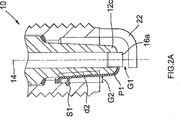
プラグ10はまた、前記スリーブ12の一部を囲む導電性シェル20を備え、スリーブ12はシェル20内に取り付けられている。シェル20は外側ねじ切り部20aを有し、それによってプラグ10をエンジン・ヘッドに取り付けることができる。シェル20は、シェル20の端部20c上に形成された端部表面20bを有し、これはほぼ環状である。端部表面20bは、軸14の径方向に延びている。端部20cは普通、中空の円筒形をしており、内側表面20dを有する。端部20cは、表面20bからシェル20の内向きに突起するフランジ20eまでの軸方向距離「d2」を越えて延びている。フランジ20eは、スリーブ12の端部12cの外側表面12bに近接して突出している。シール21が、フランジ20eとスリーブ12の間の隙間を密封する。フランジ20eとシェル20の端部表面20bの間には、シェル20の端部20cの内側表面20dとスリーブ12の端部12cの外側表面12bの間に間隙がある。外側表面12bは、ほぼ切頭円錐形状であり、それによって間隙は幅が先端16aに向かう方向に大きくなる。端部12cは、その間に間隙を備えてシェル20の端部20cを通って延び、表面20bを越えて延び、表面20bを通過する。端部12cは、距離「d1」だけ表面20bを越えて突出する。
The
プラグ10はまた、前記シェル20上に取り付けられ、これに電気接続された第2の電極22を備えている。特に、第2の電極22は、表面20bに溶接されており、先端16aと対向する関係に位置決めされた先端22aまでJ字形に突出し、それによって先端16a及び22aは共に、点火隙間「G1」を画定する。
The
プラグ10は、シェル20のねじ切り部20aによりエンジン・ヘッド内に取り付けられ、それによって第1の電極16の先端16a、先端16aに隣接するスリーブ12の端部、及び第2の電極22は、エンジンの燃焼室内に突出する。高電圧が端子18に加えられると、プラグ10の通常動作中に、火花が作り出され、それによって燃焼室内の燃料混合気を点火させる。火花は隙間G1を通過することを意図している。しかし、使用中は、汚れ(炭素の堆積)が絶縁スリーブ12の端部12c上に生じる。これにより、隙間G1を飛び越える代わりに、電気がスリーブ12の表面12bに沿って、表面12bと20dの間の間隙内に流れることができるようになる。この場合、火花は距離d2に沿ったどこかでシェル20まで飛ぶ可能性がある。火花が表面20b近くまで飛ばない場合、火花は少なくともある程度、シェル20及びスリーブ12によって燃料混合気から遮蔽されて、点火が不確実になる。実際、電気はフランジ20e全体にわたって端部12cに沿って進む可能性があり、火花は生じないことがある。この可能性を少なくするため、d1を隙間G1から離れた火花を阻止するように、またd1とd2の両方を火花が生じない可能性を低くするように、距離d1及びd2を比較的長くすることが望ましい。しかし実際、d1は普通、他の理由によって決まり、それによって表面12bと20dの間の間隙を代わりに大きくしなければならない可能性がある。
The
本発明による第1の例示的点火プラグ30が、図1B及び2Bに示されている。プラグ30は、絶縁スリーブの形でのみ上に説明したプラグ10とは異なるが、プラグ10の同様の部品に関して使用した同一の参照番号を、プラグ30の部品に関して使用し、その説明は繰り返さない。プラグ30の絶縁スリーブ12はまた、その端部12cが突起32を備えているということを除いては、プラグ10のスリーブ12と同一である。この突起32は、スリーブ12と一体であり、端部12cから突出し、それによってシェル20の端部表面20bの領域内で、端部12cとシェル20の端部20cの間の間隙が、「G2」で示されている隙間まで小さくなる。というのは、意図する隙間G1に飛ばない場合、火花が飛ぶ可能性が最も高い二次点火隙間が設けられるからである。突起32は、スリーブ12の周りに環状リブとして延び、それによって突起32と表面20dの間の間隙は、スリーブ12の周りで0.8mmとほぼ等しくなる。
A first
断面では、プラグ30の軸方向に、突起32はドーム状の正弦形状をしており、ドームの頂点は表面20bとほぼ同一平面にある。すなわち、突起32は、スリーブ20の端部表面20bと同一平面の中心線に位置合わせされている。
In the cross section, the
図1A及び2A、図1B及び2Bではそれぞれ、プラグ10及び30の距離d1及びd2は、比較する目的で同一に示しているが、実際はプラグ30の距離d1及びd2を、同じ動作状態にするためプラグ10の距離と比べて小さくすることができる。
In FIGS. 1A and 2A, and FIGS. 1B and 2B, the distances d1 and d2 of the
プラグ30は、通常の状態では、プラグ10と同様に動作する、すなわち火花が隙間G1で発生する。しかし、汚れた場合、突起32は状況が変わる。図2Aでは、線P1は、電気が先端16aからシェル20まで移動する可能性のある代替経路を示している。矢印S1は、火花が形成する1つの可能性のある位置を示すが、火花は前に述べたように距離d2に沿ったどこでも形成することができる。これに対して、図2Bでは、線P2は電気用の可能な代替経路を示している。電気が突起32を通る可能性は低く、それによって火花が隙間G2にわたって生じる可能性が高い。
In a normal state, the
図3では、本発明による第2の例示的火花プラグ40が示されている。プラグ40は、シェル20の内側にあるスリーブ12の端部12cの一部が、環状リブの形をしている経路延長波状起伏42を備えているという点だけが、プラグ30と異なる。これらの波状起伏42はスリーブ12の残りの部分と一体であり、火花を形成することなく電気がフランジ20eまで移動するのではなく、火花が隙間G2で生じる可能性がさらに高くなる。
In FIG. 3, a second
図4A、4B、及び4Cは、別の公知の点火プラグ50を示している。点火プラグ50は、以下に説明する点においてのみプラグ10と異なり、したがってプラグ10に関して使用したのと同じ参照番号を、プラグ50内の部品に関連して使用し、その説明は繰り返さない。シェル20の端部20cは異なる形状をしており、スリーブ12の端部12cは異なる形状をしており、また端子18に隣接するスリーブ12の一部12dは異なる形状をしているという点において、プラグ50はプラグ10と異なる。
4A, 4B, and 4C show another
特に、シェル20の端部20cは、端部表面20bから延びる内部フランジ20fを備えており、その中に段差20gがある。端部12cの形状は、先端16aに隣接する端部と段差20gの間ではほぼ円筒形であり、その後シール21に対して切頭円錐形状に外向きにテーパ状をしている。一部12dは、経路延長波状起伏12eを備えており、これによって端子18とシェル20の間の長さX上での短絡の可能性が低くなる。
In particular, the
プラグ50の動作中、通常の状態では、火花は隙間G1で生じる。しかし、スリーブ12上が汚れている場合、電気はスリーブの表面に沿って移動し、フランジ20fに飛び、それによって二次点火隙間G2が設けられる。しかし、隙間G2は、図4Cに示す点Y及びZの間のかなりの軸方向長さをもち、火花はこの距離に沿ったどこでも生じる可能性がある。さらに、フランジ20fは、シェルの残りの部分よりも先端16aに近づき、それによって隙間G1よりも隙間G2で火花が生じる可能性が高くなる。
During the operation of the
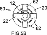
図5A及び5B、図5C及び5D、並びに図5Eはそれぞれ、1つ又は複数の追加電極を備える、3つの公知の設計のプラグを示している。プラグ10に関連して使用したのと同じ参照番号を、同様の部品に使用するが、その説明は繰り返さない。図5A及び5Bでは、プラグ60は、全てシェル20に溶接された3つの追加電極62を有し、第2の電極22を含む4つの電極は軸14の周りに均一に分配されている。電極62は、第2の電極22の先端22aよりも先端16aから離れた、先端62aまで突出するように配置されている。特に、電極62は、スリーブ12の端部と対向する関係にある点まで延びている。プラグ60の動作中、3つの電極62により、3つの代替二次点火隙間G2が設けられ、電気がスリーブ12の端部の上に流れ、電極62まで飛ぶと、汚れている場合には、これらの隙間が動作するようになる。
FIGS. 5A and 5B, FIGS. 5C and 5D, and FIG. 5E each show three known designs of plugs with one or more additional electrodes. The same reference numbers used in connection with
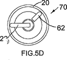
図5C及び5Dは公知のプラグ70を示しており、このプラグはプラグ60と同様であるが、スリーブ12の端部の側面と対向する関係に先端を有する追加電極62を1つだけ備えている。
FIGS. 5C and 5D show a
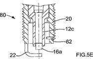
図5Eは、プラグ60、70と同様であるが、シェル20上に取り付けられ、円筒形の端部12cの表面に向かって内向きに突出するピンによって設けられた追加電極62を有する公知のプラグ80を示している。
FIG. 5E is similar to the
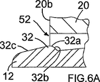
図6Aから6Gは、図1B及び2Bに示す突起の代わりに、又は図3に示す突起32の代わりに使用できる、突起32の代替形態を示している。図6Aでは、突起32は非対称であり、表面20bと同一平面にある頂点32aと、ほぼ正弦形の(先端16aから最も離れている)内側表面32bと、プラグの軸14に対して一定の角度で傾斜する(先端16aに最も近い)外側表面32cを有する。図6Bでは、突起は対称であり、2つの正弦側表面32bと32cの間に延びる平らな頂点32aを有し、頂点32aは、そのほとんどが表面20cに対して、表面20bを通って延びる表面32bに隣接して外向きに位置決めされるように配置されている。図6Cでは、突起32は、表面20bと同一平面にある尖った頂点32aを有し、側表面32b、32cは軸14に対して反対の角度で傾斜し、対称な突起を作り出す。図6Dでは、突起32は図1B、2B及び3と同じ形、すなわち正弦形をしており、その頂点32aは表面20bと同一平面にある。図6Eでは、突起32は半円形をしており、その頂点32aは表面20bと同一平面にある。図6Fでは、突起32は図6Bに示すものと同様の形をしているが、突起は先端16aまでは延びていない。図6Gでは、突起は図6Aに示すものと同様の形をしているが、側表面32cはより急傾斜である。
6A to 6G show alternative forms of
突起32の側表面32b、32cは、軸14に対して最大60度の角度で傾斜していることが好ましい。プラグ内の下で生じる火花を減らすためには、30度を超える角度が好ましい。
The side surfaces 32b and 32c of the
公知のプラグ10、50及び本発明によるプラグ30に、冷却汚れ試験を行った。この試験では、車両を−10℃まで冷却し、エンジンを始動させ、第1、第2、及び第3のギアにより最大50km/時間まで直ちに加速し、この回転数を2秒間保持し、エンジンを停止させ、温度が再び下がるまで待機し、車が再び始動しなくなるまで、又は上述の回転数に達することができなくなるような不点火まで始動、駆動、及び冷却段階を繰り返した。この試験は、洗浄が起こるのに充分なだけ温度が上がることなく、プラグ上に冷却汚れが生じるように設計されている。明らかに、試験過程を繰り返すことができる回数(サイクル)が多ければ多いほど、プラグの性能は優れている。これらの試験では、プラグ10は平均11.8サイクルを達成し、プラグ50は平均9.0サイクルを達成し、本発明によるプラグ30は26.7サイクルを達成した。
A cooling dirt test was performed on the known plugs 10 and 50 and the
Claims (7)
Applications Claiming Priority (2)
| Application Number | Priority Date | Filing Date | Title |
|---|---|---|---|
| GBGB0127218.6A GB0127218D0 (en) | 2001-11-13 | 2001-11-13 | Spark plug |
| PCT/GB2002/005000 WO2003043152A1 (en) | 2001-11-13 | 2002-11-05 | Spark plug |
Publications (3)
| Publication Number | Publication Date |
|---|---|
| JP2005510023A JP2005510023A (en) | 2005-04-14 |
| JP2005510023A5 JP2005510023A5 (en) | 2006-01-05 |
| JP4187654B2 true JP4187654B2 (en) | 2008-11-26 |
Family
ID=9925682
Family Applications (1)
| Application Number | Title | Priority Date | Filing Date |
|---|---|---|---|
| JP2003544870A Expired - Fee Related JP4187654B2 (en) | 2001-11-13 | 2002-11-05 | Spark plug |
Country Status (6)
| Country | Link |
|---|---|
| US (2) | US7057332B2 (en) |
| EP (1) | EP1444760B3 (en) |
| JP (1) | JP4187654B2 (en) |
| DE (1) | DE60222797T3 (en) |
| GB (2) | GB0127218D0 (en) |
| WO (1) | WO2003043152A1 (en) |
Cited By (1)
| Publication number | Priority date | Publication date | Assignee | Title |
|---|---|---|---|---|
| EP3073590A1 (en) | 2015-03-26 | 2016-09-28 | NGK Spark Plug Co., Ltd. | Spark plug |
Families Citing this family (9)
| Publication number | Priority date | Publication date | Assignee | Title |
|---|---|---|---|---|
| DE10160301A1 (en) * | 2001-12-07 | 2003-06-18 | Bosch Gmbh Robert | Sealing device has ceramic base with peripheral groove(s) on outer wall in whose vicinity metal housing is pressed onto ceramic base in shape-locking manner and partially soldered |
| GB2404422B (en) * | 2003-07-29 | 2006-07-05 | Federal Mogul Ignition Uk Ltd | Spark plug |
| JP4970892B2 (en) * | 2006-10-24 | 2012-07-11 | 株式会社デンソー | Spark plug for internal combustion engine |
| KR101522058B1 (en) * | 2008-03-18 | 2015-05-20 | 니혼도꾸슈도교 가부시키가이샤 | Spark plug |
| EP2330702B1 (en) * | 2008-09-24 | 2018-08-01 | NGK Sparkplug Co., Ltd. | Spark plug |
| WO2010128592A1 (en) * | 2009-05-07 | 2010-11-11 | 日本特殊陶業株式会社 | Spark plug |
| EP2652848B1 (en) * | 2010-12-14 | 2018-09-19 | Federal-Mogul Ignition Company | Corona igniter having shaped insulator |
| US10578073B2 (en) | 2017-04-11 | 2020-03-03 | Tenneco Inc. | Igniter assembly, insulator therefor and methods of construction thereof |
| JP6781141B2 (en) * | 2017-12-08 | 2020-11-04 | 日本特殊陶業株式会社 | Spark plug |
Family Cites Families (14)
| Publication number | Priority date | Publication date | Assignee | Title |
|---|---|---|---|---|
| GB188874A (en) | 1921-10-26 | 1922-11-23 | William Henry Shute | Improvements in or relating to sparking plugs of internal combustion engines |
| US1742784A (en) * | 1925-05-02 | 1930-01-07 | Ac Spark Plug Co | Spark plug |
| FR759221A (en) | 1933-07-13 | 1934-01-31 | Spark plug | |
| FR829344A (en) * | 1937-02-18 | 1938-06-20 | Improvement in spark plugs | |
| JPS5910549B2 (en) | 1977-04-11 | 1984-03-09 | 株式会社日本自動車部品総合研究所 | spark plug |
| US4211952A (en) * | 1977-04-07 | 1980-07-08 | Nippon Soken, Inc. | Spark plug |
| JPS5625194Y2 (en) | 1978-10-17 | 1981-06-13 | ||
| JPS5571481U (en) | 1978-11-09 | 1980-05-16 | ||
| JPS60153492U (en) | 1984-03-22 | 1985-10-12 | 日本特殊陶業株式会社 | spark plug |
| JPS6129085A (en) | 1984-07-20 | 1986-02-08 | 株式会社デンソー | Ignition plug for internal combustion engine |
| JPS62217589A (en) | 1986-03-18 | 1987-09-25 | 株式会社デンソー | Spark plug for internal combustion engine |
| JPH0355785A (en) | 1989-04-19 | 1991-03-11 | Ngk Spark Plug Co Ltd | Heater built-in spark plug and its manufacture |
| JP3671485B2 (en) | 1995-11-16 | 2005-07-13 | 日本特殊陶業株式会社 | Spark plug for internal combustion engine |
| DE10015916A1 (en) | 2000-03-30 | 2001-10-04 | Bosch Gmbh Robert | Spark plug for internal combustion engine, includes shaded zone on insulator foot in region of intermediate space, to provide shaded zone in radial direction |
-
2001
- 2001-11-13 GB GBGB0127218.6A patent/GB0127218D0/en not_active Ceased
-
2002
- 2002-11-05 EP EP02777476A patent/EP1444760B3/en not_active Expired - Lifetime
- 2002-11-05 US US10/495,201 patent/US7057332B2/en not_active Ceased
- 2002-11-05 JP JP2003544870A patent/JP4187654B2/en not_active Expired - Fee Related
- 2002-11-05 GB GB0225732A patent/GB2382842C/en not_active Expired - Fee Related
- 2002-11-05 WO PCT/GB2002/005000 patent/WO2003043152A1/en active IP Right Grant
- 2002-11-05 DE DE60222797T patent/DE60222797T3/en not_active Expired - Lifetime
- 2002-11-05 US US12/401,120 patent/USRE41672E1/en not_active Expired - Lifetime
Cited By (2)
| Publication number | Priority date | Publication date | Assignee | Title |
|---|---|---|---|---|
| EP3073590A1 (en) | 2015-03-26 | 2016-09-28 | NGK Spark Plug Co., Ltd. | Spark plug |
| US9608411B2 (en) | 2015-03-26 | 2017-03-28 | Ngk Spark Plug Co., Ltd. | Spark plug |
Also Published As
| Publication number | Publication date |
|---|---|
| GB0127218D0 (en) | 2002-01-02 |
| GB2382842B (en) | 2005-06-15 |
| WO2003043152A1 (en) | 2003-05-22 |
| GB2382842C (en) | 2008-11-24 |
| EP1444760A1 (en) | 2004-08-11 |
| DE60222797T3 (en) | 2009-10-01 |
| DE60222797D1 (en) | 2007-11-15 |
| EP1444760B1 (en) | 2007-10-03 |
| US7057332B2 (en) | 2006-06-06 |
| GB2382842A (en) | 2003-06-11 |
| USRE41672E1 (en) | 2010-09-14 |
| DE60222797T2 (en) | 2008-07-03 |
| GB0225732D0 (en) | 2002-12-11 |
| EP1444760B3 (en) | 2009-02-25 |
| US20050001526A1 (en) | 2005-01-06 |
| JP2005510023A (en) | 2005-04-14 |
Similar Documents
| Publication | Publication Date | Title |
|---|---|---|
| JP3269032B2 (en) | Spark plug and ignition system for internal combustion engine using the same | |
| US4795937A (en) | Spark plug with combined surface and air spark paths | |
| US7077100B2 (en) | Combined fuel injection valve-ignition plug | |
| US7768184B2 (en) | Spark plug with stream shaper to shape tumble vortex into desired stream in combustion chamber | |
| EP1102373B1 (en) | Spark plug | |
| JP4187654B2 (en) | Spark plug | |
| US10868408B2 (en) | Spark plug | |
| CA2365138C (en) | Current peaking sparkplug | |
| US3434012A (en) | Glow igniter | |
| EP0746889B1 (en) | Spark plug | |
| KR20150129036A (en) | Wear protection feature for corona igniter | |
| WO2021215301A1 (en) | Spark plug for internal combustion engine | |
| US7262547B2 (en) | Spark plug element having defined dimensional parameters for its insulator component | |
| US5502352A (en) | Spark plug having horizontal discharge | |
| US4007391A (en) | Igniters | |
| US7541724B2 (en) | Spark plug requiring low discharge voltage and having high self-cleaning capability | |
| EP1671405B1 (en) | Spark plug | |
| EP0758152B1 (en) | A spark plug | |
| JP2805781B2 (en) | Spark plug for internal combustion engine | |
| GB2391264A (en) | Spark plug | |
| US10333281B2 (en) | Spark plug | |
| JPH09106881A (en) | Spark plug | |
| JP6661245B2 (en) | Spark plug | |
| GB2032516A (en) | Sparking plug | |
| JP2005079095A (en) | Spark plug |
Legal Events
| Date | Code | Title | Description |
|---|---|---|---|
| A521 | Request for written amendment filed |
Free format text: JAPANESE INTERMEDIATE CODE: A523 Effective date: 20050913 |
|
| A621 | Written request for application examination |
Free format text: JAPANESE INTERMEDIATE CODE: A621 Effective date: 20050913 |
|
| A977 | Report on retrieval |
Free format text: JAPANESE INTERMEDIATE CODE: A971007 Effective date: 20070918 |
|
| A131 | Notification of reasons for refusal |
Free format text: JAPANESE INTERMEDIATE CODE: A131 Effective date: 20070925 |
|
| A521 | Request for written amendment filed |
Free format text: JAPANESE INTERMEDIATE CODE: A523 Effective date: 20071225 |
|
| A131 | Notification of reasons for refusal |
Free format text: JAPANESE INTERMEDIATE CODE: A131 Effective date: 20080229 |
|
| TRDD | Decision of grant or rejection written | ||
| A01 | Written decision to grant a patent or to grant a registration (utility model) |
Free format text: JAPANESE INTERMEDIATE CODE: A01 Effective date: 20080812 |
|
| A01 | Written decision to grant a patent or to grant a registration (utility model) |
Free format text: JAPANESE INTERMEDIATE CODE: A01 |
|
| A61 | First payment of annual fees (during grant procedure) |
Free format text: JAPANESE INTERMEDIATE CODE: A61 Effective date: 20080909 |
|
| R150 | Certificate of patent or registration of utility model |
Free format text: JAPANESE INTERMEDIATE CODE: R150 |
|
| FPAY | Renewal fee payment (event date is renewal date of database) |
Free format text: PAYMENT UNTIL: 20110919 Year of fee payment: 3 |
|
| FPAY | Renewal fee payment (event date is renewal date of database) |
Free format text: PAYMENT UNTIL: 20110919 Year of fee payment: 3 |
|
| FPAY | Renewal fee payment (event date is renewal date of database) |
Free format text: PAYMENT UNTIL: 20120919 Year of fee payment: 4 |
|
| FPAY | Renewal fee payment (event date is renewal date of database) |
Free format text: PAYMENT UNTIL: 20120919 Year of fee payment: 4 |
|
| FPAY | Renewal fee payment (event date is renewal date of database) |
Free format text: PAYMENT UNTIL: 20130919 Year of fee payment: 5 |
|
| R250 | Receipt of annual fees |
Free format text: JAPANESE INTERMEDIATE CODE: R250 |
|
| LAPS | Cancellation because of no payment of annual fees |


