JP4185659B2 - Optical recording medium, information recording apparatus, and information reproducing apparatus - Google Patents
Optical recording medium, information recording apparatus, and information reproducing apparatus Download PDFInfo
- Publication number
- JP4185659B2 JP4185659B2 JP2000337582A JP2000337582A JP4185659B2 JP 4185659 B2 JP4185659 B2 JP 4185659B2 JP 2000337582 A JP2000337582 A JP 2000337582A JP 2000337582 A JP2000337582 A JP 2000337582A JP 4185659 B2 JP4185659 B2 JP 4185659B2
- Authority
- JP
- Japan
- Prior art keywords
- recording layer
- recording
- track
- information
- zone
- Prior art date
- Legal status (The legal status is an assumption and is not a legal conclusion. Google has not performed a legal analysis and makes no representation as to the accuracy of the status listed.)
- Expired - Fee Related
Links
Images


Classifications
-
- G—PHYSICS
- G11—INFORMATION STORAGE
- G11B—INFORMATION STORAGE BASED ON RELATIVE MOVEMENT BETWEEN RECORD CARRIER AND TRANSDUCER
- G11B7/00—Recording or reproducing by optical means, e.g. recording using a thermal beam of optical radiation by modifying optical properties or the physical structure, reproducing using an optical beam at lower power by sensing optical properties; Record carriers therefor
- G11B7/007—Arrangement of the information on the record carrier, e.g. form of tracks, actual track shape, e.g. wobbled, or cross-section, e.g. v-shaped; Sequential information structures, e.g. sectoring or header formats within a track
-
- G—PHYSICS
- G11—INFORMATION STORAGE
- G11B—INFORMATION STORAGE BASED ON RELATIVE MOVEMENT BETWEEN RECORD CARRIER AND TRANSDUCER
- G11B7/00—Recording or reproducing by optical means, e.g. recording using a thermal beam of optical radiation by modifying optical properties or the physical structure, reproducing using an optical beam at lower power by sensing optical properties; Record carriers therefor
- G11B2007/0003—Recording, reproducing or erasing systems characterised by the structure or type of the carrier
- G11B2007/0009—Recording, reproducing or erasing systems characterised by the structure or type of the carrier for carriers having data stored in three dimensions, e.g. volume storage
- G11B2007/0013—Recording, reproducing or erasing systems characterised by the structure or type of the carrier for carriers having data stored in three dimensions, e.g. volume storage for carriers having multiple discrete layers
-
- G—PHYSICS
- G11—INFORMATION STORAGE
- G11B—INFORMATION STORAGE BASED ON RELATIVE MOVEMENT BETWEEN RECORD CARRIER AND TRANSDUCER
- G11B7/00—Recording or reproducing by optical means, e.g. recording using a thermal beam of optical radiation by modifying optical properties or the physical structure, reproducing using an optical beam at lower power by sensing optical properties; Record carriers therefor
- G11B7/08—Disposition or mounting of heads or light sources relatively to record carriers
- G11B7/085—Disposition or mounting of heads or light sources relatively to record carriers with provision for moving the light beam into, or out of, its operative position or across tracks, otherwise than during the transducing operation, e.g. for adjustment or preliminary positioning or track change or selection
- G11B7/08505—Methods for track change, selection or preliminary positioning by moving the head
- G11B7/08511—Methods for track change, selection or preliminary positioning by moving the head with focus pull-in only
Landscapes
- Optical Recording Or Reproduction (AREA)
- Optical Record Carriers And Manufacture Thereof (AREA)
Description
【0001】
【発明の属する技術分野】
本発明は、複数の記録層を有する光記録媒体に情報を記録する情報記録装置等に関する。
【0002】
【従来の技術】
記録可能な光記録媒体として、DVD−RAMディスクが知られている。このディスクは単独の記録層を有する、いわゆるランド・グルーブ・シングル・スパイラル構造を採り、1回転に1回、案内溝(グルーブ)を1トラック分オフセットさせることにより、ランドとグルーブとを交互に接続させて1つのスパイラルを形成するようにしている。このスパイラルをトレースすることにより、すべてのランドとグルーブを連続してトレースすることが可能となる。したがって、物理アドレスはランドトラックとグルーブトラックとで交互に更新する。
【0003】
【発明が解決しようとする課題】
しかし、上記のDVD―RAMは単独の記録層を備えるものであるため、記録容量を増加させるためには、記録層を複数設ける必要がある。かつ、再生を容易なものとすることが出来る複数の記録層を有する光記録媒体に情報を記録する情報記録装置等を提供することを目的とする。
【0004】
【課題を解決するための手段】
上記課題を解決するために、請求項1に記載の発明は、ランドトラック及びグルーブトラックの両方に情報を記録するダブルスパイラル構造の少なくとも第1の記録層と第2の記録層とを有するディスク状の光記録媒体に情報を記録する情報記録装置であって、前記各記録層に形成されるランドトラック及びグルーブトラックに情報を記録する記録手段と、少なくとも前記第1の記録層及び前記第2の記録層の一部を含む半径方向に分割された複数ゾーンに情報を記録すると共に、各ゾーン内で隣接する前記記録層に形成されたランドトラック及びグルーブトラックの記録方向が互いに異なるように情報を記録するように記録手段を制御する制御手段と、を備え、前記制御手段は、前記記録層のうち第1の記録層では、前記ランドトラック又は前記グルーブトラックの何れかに前記光記録媒体の外周から内周に向かう方向に第1の情報を記録するように前記記録手段を制御し、前記記録層のうち第2の記録層では、前記ランドトラック又は前記グルーブトラックの何れかに前記光記録媒体の内周から外周に向かう方向に前記第1の情報に続く第2の情報を記録するように前記記録手段を制御することを特徴とする。
【0005】
この情報記録装置によれば、ゾーン内における一記録層に形成されたランドトラック又はグルーブトラックの何れかに記録を終えた後に、当該ゾーン内の隣接する記録層に形成された当該ランドトラック又は当該グルーブトラックの何れかへピックアップの焦点を移動させ、更に互いに隣接する記録層に形成された当該ランドトラック又は当該グルーブトラックの何れかの記録方向を互いに異ならせることにより、ゾーン内の複数の記録層に形成された当該ランドトラック及び当該グルーブトラックの記録が可能となり、ピックアップを半径方向に大きく移動させる情報を記録することができる。
【0006】
上記課題を解決するために、請求項2に記載の発明は、ランドトラック及びグルーブトラックの両方に情報を記録するダブルスパイラル構造の少なくとも第1の記録層と第2の記録層とを有するディスク状の光記録媒体に情報を記録する情報記録方法であって、前記各記録層に形成されるランドトラック及びグルーブトラックに情報を記録する記録工程と、少なくとも前記第1の記録層及び前記第2の記録層の一部を含む半径方向に分割された複数ゾーンに情報を記録すると共に、各ゾーン内で隣接する前記記録層に形成されたランドトラック及びグルーブトラックの記録方向が互いに異なるように情報を記録するように制御する制御工程と、を備え、前記制御工程において、前記記録層のうち第1の記録層では、前記ランドトラック又は前記グルーブトラックの何れかに前記光記録媒体の外周から内周に向かう方向に第1の情報を記録するように制御し、前記記録層のうち第2の記録層では、前記ランドトラック又は前記グルーブトラックの何れかに前記光記録媒体の内周から外周に向かう方向に前記第1の情報に続く第2の情報を記録するように制御することを特徴とする。
【0007】
この情報記録方法によれば、ゾーン内における一記録層に形成されたランドトラック又はグルーブトラックの何れかの記録を終えた後に、当該ゾーン内の隣接する記録層に形成された当該ランドトラック又は当該グルーブトラックの何れかへピックアップの焦点を移動させ、更に互いに隣接する記録層に形成された当該ランドトラック及び当該グルーブトラックの記録方向を互いに異ならせることにより、ゾーン内の複数の記録層に形成された当該ランドトラック及び当該グルーブトラックの記録が可能となり、ピックアップを半径方向に大きく移動させることなく情報の記録が可能となる。
【0008】
上記課題を解決するために、請求項3に記載の発明は、ランドトラック及びグルーブトラックの両方に情報を記録するダブルスパイラル構造の少なくとも第1の記録層と第2の記録層とを有する光記録媒体の情報を再生する情報再生装置であって、前記第1の記録層及び前記第2の記録層の一部を少なくとも含む半径方向に分割されたゾーン毎に前記情報を再生すると共に、前記ゾーン内で隣接する前記各記録層に形成されたランドトラック及びグルーブトラックでは互いに異なる方向に情報を再生する再生手段と、前記再生手段によりピックアップの焦点を一記録層に形成されたランドトラック又はグルーブトラックの何れかから隣接する記録層に形成されたランドトラック又はグルーブトラックの何れかへ移動させるフォーカスジャンプ手段と、前記グルーブトラックと前記ランドトラックとの間での読み取りトラックの切り換えに応じてトラッキングの極性を切り換える極性切換手段と、前記ゾーン内における一記録層に形成されたランドトラック又はグルーブトラックの何れかの再生を終えた後に、前記極性切替手段により前記トラッキングの極性を切り換えて当該ゾーン内の他の記録層に形成されたランドトラック又はグルーブトラックの何れかへ前記ピックアップの焦点を移動するように前記フォーカスジャンプ手段を制御する制御手段と、を備えることを特徴とする。
【0009】
この情報再生装置によれば、ゾーン内における一記録層に形成されたランドトラック又はグルーブトラックの何れかの再生を終えた後に、当該ゾーン内の隣接する記録層に形成されたランドトラック又はグルーブトラックの何れかへピックアップの焦点を移動させ、更に互いに隣接する記録層に形成されたランドトラック及びグルーブトラックの再生方向を互いに異ならせることにより、ゾーン内の複数の記録層に形成されたランドトラック及びグルーブトラックの再生が可能となり、ピックアップを半径方向に大きく移動させることなく情報の再生が可能となる。
【0010】
上記課題を解決するために、請求項4に記載の発明は、ランドトラック及びグルーブトラックの両方に情報を記録するダブルスパイラル構造の少なくとも第1の記録層と第2の記録層とを有する光記録媒体の情報を再生する情報再生方法であって、前記第1の記録層及び前記第2の記録層の一部を少なくとも含む半径方向に分割されたゾーン毎に前記情報を再生すると共に、前記ゾーン内で隣接する前記各記録層に形成されたランドトラック及びグルーブトラックでは互いに異なる方向に情報を再生する再生工程と、前記再生工程においてピックアップの焦点を一記録層に形成されたランドトラック又はグルーブトラックの何れかから隣接する記録層に形成されたランドトラック又はグルーブトラックの何れかへ移動させるフォーカスジャンプ工程と、前記グルーブトラックと前記ランドトラックとの間での読み取りトラックの切り換えに応じてトラッキングの極性を切り換える極性切換工程と、前記ゾーン内における一記録層に形成されたランドトラック又はグルーブトラックの何れかの再生を終えた後に、前記極性切替工程において前記トラッキングの極性を切り換えて当該ゾーン内の他の記録層に形成されたランドトラック又はグルーブトラックの何れかへ前記ピックアップの焦点を移動するように制御する制御工程と、を備えることを特徴とする。
【0011】
この情報再生方法によれば、ゾーン内における一記録層に形成されたランドトラック又はグルーブトラックの何れかの再生を終えた後に、当該ゾーン内の隣接する記録層に形成されたランドトラック又はグルーブトラックの何れかへピックアップの焦点を移動させ、更に互いに隣接する記録層に形成されたランドトラック及びグルーブトラックの再生方向を互いに異ならせることにより、ゾーン内の複数の記録層に形成されたランドトラック及びグルーブトラックの再生が可能となり、ピックアップを半径方向に大きく移動させることなく情報の再生が可能となる。
【0030】
なお、本発明の理解を容易にするために添付図面の参照符号を括弧書きにて付記するが、それにより本発明が図示の形態に限定されるものではない。
【0031】
【発明の実施の形態】
−第1の実施形態−
以下、図1〜図3を参照して、本発明の光記録媒体の第1の実施形態について説明する。
【0032】
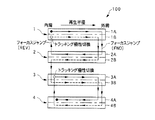
図1は第1の実施形態の光記録媒体としての光ディスクの記録層の構成を模式的に示す図、図2は各記録層の構成を模式的に示す図である。図1に示すように光ディスク100は順次積層される第1の記録層1、第2の記録層2、第3の記録層3および第4の記録層4を備える。第1の記録層1にはグルーブトラック1Aおよびランドトラック1Bが、第2の記録層2にはグルーブトラック2Aおよびランドトラック2Bが、第3の記録層3にはグルーブトラック3Aおよびランドトラック3Bが、第4の記録層4にはグルーブトラック4Aおよびランドトラック4Bが、それぞれ螺旋状に形成されている。すなわち、各記録層はグルーブトラックおよびランドトラックの両方に情報を記録可能なダブルスパイラル構造を有する。
【0033】
図2(a)および図2(c)に示すように第1の記録層1および第3の記録層3は正方向のスパイラル構造を、図2(b)および図2(d)に示すように第2の記録層2および第4の記録層4は逆方向のスパイラル構造を、それぞれとる。なお、図2においてスパイラルの正方向および逆方向は便宜的に定めたものであり、スパイラルの正逆は互いに逆方向であることを意味するに過ぎない。スパイラルの正方向あるいは逆方向は絶対的な方向を定めるものではない。
【0034】
図1および図2(a)に示すように、第1の記録層1のグルーブトラック1Aおよびランドトラック1Bには、それぞれ光ディスク100の内周から外周に向かう方向に情報が記録される。図1および図2(b)に示すように、第2の記録層2のグルーブトラック2Aおよびランドトラック2Bには、それぞれ光ディスク100の外周から内周に向かう方向に情報が記録される。図1および図2(c)に示すように、第3の記録層3のグルーブトラック3Aおよびランドトラック3Bには、それぞれ光ディスク100の内周から外周に向かう方向に情報が記録される。図1および図2(d)に示すように、第4の記録層4のグルーブトラック4Aおよびランドトラック4Bには、それぞれ光ディスク100の外周から内周に向かう方向に情報が記録される。図2(a)〜(d)に示す矢印P1〜P4は、それぞれ第1〜第4の記録層における記録方向(再生方向)を示している。
【0035】
図1に示すように、光ディスク100における物理アドレスは、第1の記録層1のグルーブトラック1A、第2の記録層2のグルーブトラック2A、第1の記録層1のランドトラック1B、第2の記録層2のランドトラック2B、第3の記録層3のランドトラック3B、第4の記録層4のランドトラック4B、第3の記録層3のグルーブトラック3A、第4の記録層4のグルーブトラック4Aの順に割当てられている。
【0036】
図3は光ディスク100に情報を記録するとともに、光ディスク100に記録された情報を再生する情報記録再生装置50の構成を示すブロック図である。図3に示すように、情報記録再生装置50はレーザー光51Aにより光ディスク100の各記録層に情報を書き込むとともに各記録層の情報を読み取るピックアップ51と、ピックアップ51からの情報に基づいてトラッキングのずれを検出するトラッキング検出回路52と、グルーブトラックとランドトラックとの間での読み取りトラックの切換えに応じてトラッキングの極性を切換える極性切換回路53と、トラッキング検出回路52から出力された信号を整形する位相補償回路54と、位相補償回路54からの信号を受ける駆動回路55と、駆動回路55からの信号を受けてピックアップ51を駆動し、これによりトラッキングを調整するトラッキングアクチュエータ56と、ピックアップ51からの情報に基づいてフォーカスのずれを検出するフォーカス検出回路58と、フォーカス検出回路58の信号を整形する位相補償回路59と、フォーカスジャンプを制御するフォーカスジャンプ制御回路60と、位相補償回路59またはフォーカスジャンプ制御回路60からの信号を受ける駆動回路61と、駆動回路61に入力する信号として位相補償回路59およびフォーカスジャンプ制御回路60の出力信号のいずれかを選択する選択スイッチ62と、駆動回路61からの信号を受けてピックアップ51のフォーカスを調整するフォーカスアクチュエータ63と、情報再生装置50の各部を制御するCPU65とを備える。
【0037】
図3に示すように、CPU65は極性切換回路53に向けてトラッキングの極性を切換える指令を送出する。また、CPU65はフォーカスジャンプ制御回路60に向けてレーザー光の焦点を別の記録層にジャンプさせるためのフォーカスジャンプの指令を送出する。
【0038】
次に、光ディスク100に記録された情報の読み取り方法について説明する。
【0039】
光ディスク100に記録された情報を上記の物理アドレス順に読み取る場合には、まず、光ディスク100を図2(a)〜図2(d)の各図について反時計回り方向に回転させつつ、ピックアップを光ディスク100の内周から外周に向けて移動させることにより、第1の記録層1のグルーブトラック1Aに記録された情報を所定の順序で読み取る。以下、光ディスク100を同一方向に回転させ続ける。
【0040】
次に、フォーカスジャンプによりピックアップの焦点を第1の記録層1から第2の記録層2に移動し、ピックアップを光ディスク100の外周から内周に向けて移動させることにより、第2の記録層2のグルーブトラック2Aに記録された情報を所定の順序で読み取る。
【0041】
次に、フォーカスジャンプによりピックアップの焦点を第2の記録層2から第1の記録層1に移動するとともにトラッキングの極性を切換える。次いで、ピックアップを光ディスク100の内周から外周に向けて移動させることにより、第1の記録層1のランドトラック1Bに記録された情報を所定の順序で読み取る。
【0042】
次に、フォーカスジャンプによりピックアップの焦点を第1の記録層1から第2の記録層2に移動し、ピックアップを光ディスク100の外周から内周に向けて移動させることにより、第2の記録層2のランドトラック2Bに記録された情報を所定の順序で読み取る。
【0043】
次に、フォーカスジャンプによりピックアップの焦点を第2の記録層2から第3の記録層3に移動し、ピックアップを光ディスク100の内周から外周に向けて移動させることにより、第3の記録層3のランドトラック3Bに記録された情報を所定の順序で読み取る。
【0044】
次に、フォーカスジャンプによりピックアップの焦点を第3の記録層3から第4の記録層4に移動し、ピックアップを光ディスク100の外周から内周に向けて移動させることにより、第4の記録層4のランドトラック4Bに記録された情報を所定の順序で読み取る。
【0045】
次に、フォーカスジャンプによりピックアップの焦点を第4の記録層4から第3の記録層3に移動するとともにトラッキングの極性を切換える。次いで、ピックアップを光ディスク100の内周から外周に向けて移動させることにより、第3の記録層3のグルーブトラック3Aに記録された情報を所定の順序で読み取る。
【0046】
次に、フォーカスジャンプによりピックアップの焦点を第3の記録層3から第4の記録層4に移動し、ピックアップを光ディスク100の外周から内周に向けて移動させることにより、第4の記録層4のランドトラック4Bに記録された情報を所定の順序で読み取る。
【0047】
以上のように、第1〜第4の記録層のグルーブトラックおよびランドトラックに記録された情報は、光ディスク100を同一方向に回転させつつ、ピックアップをディスクに対してディスクの半径方向に相対的に移動させることにより、物理アドレスの順序で読み取ることができる。また、各トラックにおける記録方向が、物理アドレス順に、光ディスク100の内周から外周へ向かう方向と、外周から内周へ向かう方向との間で繰り返されるので、ピックアップを光ディスク100の半径方向に短時間で大きく移動させる必要はなく、順次トラックをトレースするのみでフォーカスジャンプを行うことで読み取りトラックを切換えることができる。また、グルーブトラックあるいはランドトラックがなるべく連続するように物理アドレスを定めることにより、読み取りトラックの切換え時におけるトラッキング極性の切換え回数を減らすことができる。さらに、光ディスク100はダブルスパイラル構造の記録層を有するので、トラッキング極性を1回転ごとに頻繁に切換える必要もない。
【0048】
また、第1〜第4の記録層のグルーブトラックおよびランドトラックに記録される情報は、光ディスク100を同一方向に回転させつつピックアップ51をディスクの半径方向に相対的に移動させ、レーザー光を所定のタイミングで照射することにより、物理アドレスに従った順序で情報を記録することができる。
【0049】
−第2の実施形態−
以下、図4を参照して本発明の光記録媒体の第2の実施形態について説明する。
【0050】
図4は第2の実施形態の光記録媒体としての光ディスクの記録層の構成を模式的に示す図である。図4に示すように光ディスク200は互いに積層される第1の記録層11および第2の記録層12を備える。第1の記録層11にはグルーブトラック11Aおよびランドトラック11Bが、第2の記録層12にはグルーブトラック12Aおよびランドトラック12Bが、それぞれ螺旋状に形成されている。すなわち、各記録層はグルーブトラックおよびランドトラックの両方に情報を記録可能なダブルスパイラル構造を有する。
【0051】
第1の記録層1は正方向のスパイラル構造を、第2の記録層2は逆方向のスパイラル構造を、それぞれとる。なお、第1の実施形態と同様、スパイラルの正逆は互いに逆方向であることを意味するに過ぎない。
【0052】
第1の記録層11のグルーブトラック11Aおよびランドトラック11Bには、それぞれ光ディスク200の内周から外周に向かう方向に情報が記録される。第2の記録層12のグルーブトラック12Aおよびランドトラック12Bには、それぞれ光ディスク200の外周から内周に向かう方向に情報が記録される。
【0053】
光ディスク200における物理アドレスは、第1の記録層11のランドトラック11B、第2の記録層12のグルーブトラック12A、第1の記録層11のグルーブトラック11A、第2の記録層12のランドトラック12Bの順に割当てられている。
【0054】
次に、光ディスク200に記録された情報の読み取り方法について説明する。
【0055】
光ディスク200に記録された情報を上記の物理アドレス順に読み取る場合には、まず、光ディスク200を一定の方向に回転させつつ、ピックアップを光ディスク200の内周から外周に向けて移動させることにより、第1の記録層11のランドトラック11Bに記録された情報を所定の順序で読み取る。以下、光ディスク200を同一方向に回転させ続ける。
【0056】
次に、フォーカスジャンプによりピックアップの焦点を第1の記録層11から第2の記録層12に移動するとともにトラッキングの極性を切換える。次いで、ピックアップを光ディスク200の外周から内周に向けて移動させることにより、第2の記録層12のグルーブトラック12Aに記録された情報を所定の順序で読み取る。
【0057】
次に、フォーカスジャンプによりピックアップの焦点を第2の記録層12から第1の記録層11に移動し、ピックアップを光ディスク200の内周から外周に向けて移動させることにより、第1の記録層11のグルーブトラック11Aに記録された情報を所定の順序で読み取る。
【0058】
次に、フォーカスジャンプによりピックアップの焦点を第1の記録層11から第2の記録層12に移動するとともにトラッキングの極性を切換える。次いで、ピックアップを光ディスク200の外周から内周に向けて移動させることにより、第2の記録層12のランドトラック12Bに記録された情報を所定の順序で読み取る。
【0059】
以上のように、第1の記録層11および第2の記録層12のグルーブトラックおよびランドトラックに記録された情報は、光ディスク200を同一方向に回転させつつ、ピックアップをディスクに対してディスクの半径方向に相対的に移動させることにより、物理アドレスの順序で読み取ることができる。また、各トラックにおける記録方向が、物理アドレス順に、光ディスク200の内周から外周へ向かう方向と、外周から内周へ向かう方向との間で繰り返されるので、ピックアップを光ディスク200の半径方向に短時間で大きく移動させる必要はなく、フォーカスジャンプを行うことで読み取りトラックを切換えることができる。また、グルーブトラックあるいはランドトラックがなるべく連続するように物理アドレスを定めることにより、読み取りトラックの切換え時におけるトラッキング極性の切換え回数を減らすことができる。
【0060】
さらに、光ディスク200はダブルスパイラル構造の記録層を有するので、トラッキング極性を1回転ごとに頻繁に切換える必要もない。
【0061】
また、第1の記録層11および第2の記録層12のグルーブトラックおよびランドトラックに記録される情報は、光ディスク200を同一方向に回転させつつピックアップ51をディスクの半径方向に相対的に移動させ、所定のタイミングでレーザー光を照射することにより、物理アドレスに従った順序で情報を記録することができる。
【0062】
−第3の実施形態−
以下、図5を参照して、本発明の光記録媒体の第3の実施形態について説明する。
【0063】
図5は第3の実施形態の光記録媒体としての光ディスクの記録層の構成を模式的に示す図である。図5に示すように光ディスク300は互いに積層される第1の記録層21および第2の記録層22を備える。第1の記録層21にはグルーブトラック21Aおよびランドトラック21Bが、第2の記録層22にはグルーブトラック22Aおよびランドトラック22Bが、それぞれ螺旋状に形成されている。すなわち、各記録層はグルーブトラックおよびランドトラックの両方に情報を記録可能なダブルスパイラル構造を有する。
【0064】
第1の記録層21は正方向のスパイラル構造を、第2の記録層22は逆方向のスパイラル構造を、それぞれとる。なお、第1および第2の実施形態と同様、スパイラルの正方向および逆方向は便宜的に定めたものであり、スパイラルの正逆は互いに逆方向であることを意味するに過ぎない。
【0065】
図5に示すように、光ディスク300は3つのゾーンに区画されている。第1の記録層21のグルーブトラック21Aは第1のゾーン21Aa、第2のゾーン21Abおよび第3のゾーン21Acに分割されている。第1の記録層21のランドトラック21Bは第1のゾーン21Ba、第2のゾーン21Bbおよび第3のゾーン21Bcに分割されている。第2の記録層22のグルーブトラック22Aは第1のゾーン22Aa、第2のゾーン22Abおよび第3のゾーン22Acに分割されている。第2の記録層22のランドトラック22Bは第1のゾーン22Ba、第2のゾーン22Bbおよび第3のゾーン22Bcに分割されている。
【0066】
第1のゾーンにおける物理アドレスは、第1の記録層21のグルーブトラック21Aの第1のゾーン21Aa、第2の記録層22のグルーブトラック22Aの第1のゾーン22Aa、第1の記録層21のランドトラック21Bの第1のゾーン21Ba、第2の記録層22のランドトラック22Bの第1のゾーン22Baの順に割当てられる。
【0067】
第2のゾーンにおける物理アドレスは、第1の記録層21のグルーブトラック21Aの第2のゾーン21Ab、第2の記録層22のグルーブトラック22Aの第2のゾーン22Ab、第1の記録層21のランドトラック21Bの第2のゾーン21Bb、第2の記録層22のランドトラック22Bの第2のゾーン22Bbの順に割当てられる。
【0068】
第3のゾーンにおける物理アドレスは、第1の記録層21のグルーブトラック21Aの第3のゾーン21Ac、第2の記録層22のグルーブトラック22Aの第3のゾーン22Ac、第1の記録層21のランドトラック21Bの第3のゾーン21Bc、第2の記録層22のランドトラック22Bの第3のゾーン22Bcの順に割当てられる。
【0069】
また、第1の記録層21のグルーブトラック21Aおよびランドトラック21Bの各ゾーンには、それぞれ光ディスク300の内周から外周に向かう方向に情報が記録される。第2の記録層22のグルーブトラック22Aおよびランドトラック22Bの各ゾーンには、それぞれ光ディスク300の外周から内周に向かう方向に情報が記録されている。
【0070】
次に、光ディスク300に記録された情報の読み取り方法について説明する。
【0071】
まず、光ディスク300を一定の方向に回転させつつ、ピックアップを光ディスク300の内周から外周に向けて移動させることにより、ランドトラック21Aの第1のゾーン21Aaに記録された情報を所定の順序で読み取る。以下、光ディスク300を同一方向に回転させ続ける。
【0072】
次に、フォーカスジャンプによりピックアップの焦点を第1の記録層21から第2の記録層22に移動する。次いで、ピックアップを光ディスク300の内周に向けて移動させることにより、グルーブトラック22Aの第1のゾーン22Aaに記録された情報を所定の順序で読み取る。
【0073】
次に、フォーカスジャンプによりピックアップの焦点を第2の記録層22から第1の記録層21に移動するとともに、トラッキングの極性を切換える。次いで、ピックアップを光ディスク300の外周に向けて移動させることにより、ランドトラック21Bの第1のゾーン21Baに記録された情報を所定の順序で読み取る。
【0074】
次に、フォーカスジャンプによりピックアップの焦点を第1の記録層21から第2の記録層22に移動する。次いで、ピックアップを光ディスク300の内周に向けて移動させることにより、ランドトラック22Bの第1のゾーン22Baに記録された情報を所定の順序で読み取る。
【0075】
以上のように各トラックの第1ゾーンの情報を読み取った後、ピックアップを駆動して光ディスク300の外周方向にスライドさせるとともに、フォーカスジャンプによりピックアップの焦点を第2の記録層22から第1の記録層21に移動する。以下、第2のゾーンおよび第3のゾーンに記録された情報を第1のゾーンと同様の手順に従って読み取る。
【0076】
以上のように、第1の記録層11および第2の記録層22のグルーブトラックおよびランドトラックに記録された情報は、光ディスク300を同一方向に回転させつつ、ピックアップをディスクに対してディスクの半径方向に相対的に移動させることにより、物理アドレスの順序で読み取ることができる。また、各トラックにおける記録方向が、物理アドレス順に、光ディスク300の内周から外周へ向かう方向と、外周から内周へ向かう方向との間で繰り返されるので、ピックアップを光ディスク300の半径方向にほとんど移動させることなく、フォーカスジャンプを行うことで読み取りトラックを切換えることができる。また、グルーブトラックあるいはランドトラックがなるべく連続するように物理アドレスを定めることにより、読み取りトラックの切換え時におけるトラッキング極性の切換え回数を減らすことができる。
【0077】
さらに、光ディスク300はダブルスパイラル構造の記録層を有するので、トラッキング極性を頻繁に切換える必要もない。
【0078】
また、第1の記録層21および第2の記録層22のグルーブトラックおよびランドトラックに記録される情報は、光ディスク300を同一方向に回転させつつ記録ヘッドをディスクの半径方向に相対的に移動させることにより、物理アドレスに従った順序で情報を記録することができる。
【0079】
なお、図5では光ディスクを3つのゾーンに区画する場合を例示しているが、ゾーンの数はこれに限定されない。数十あるいは100以上のゾーンに区画してもよい。
【0080】
第3の実施形態では、第1の記録層1ではディスクの内周から外周に向けて情報が記録され、第2の記録層2ではディスクの外周から内周に向けて情報が記録されているが、第1の記録層1ではディスクの外周から内周に向けて情報を記録するとともに第2の記録層2ではディスクの内周から外周に向けて情報を記録し、各トラックに割当てる物理アドレスの順序を第3の実施形態と同様としてもよい。
【0081】
−第4の実施形態−
以下、図6を参照して、本発明の光記録媒体の第4の実施形態について説明する。
【0082】
図6は第4の実施形態の光記録媒体としての光ディスクの記録層の構成を模式的に示す図である。図6に示すように光ディスク400は互いに積層される第1の記録層31および第2の記録層32を備える。第1の記録層31にはグルーブトラック31Aおよびランドトラック31Bが、第2の記録層32にはグルーブトラック32Aおよびランドトラック32Bが、それぞれ螺旋状に形成されている。すなわち、各記録層はグルーブトラックおよびランドトラックの両方に情報を記録可能なダブルスパイラル構造を有する。
【0083】
第1の記録層31は正方向のスパイラル構造を、第2の記録層32は逆方向のスパイラル構造を、それぞれとる。なお、第1〜第3の実施形態と同様、スパイラルの正方向および逆方向は便宜的に定めたものであり、スパイラルの正逆は互いに逆方向であることを意味するに過ぎない。
【0084】
図6に示すように、光ディスク400は第3の実施形態と同様、3つのゾーンに区画されている。第1の記録層31のグルーブトラック31Aは第1のゾーン31Aa、第2のゾーン31Abおよび第3のゾーン31Acに分割されている。第1の記録層31のランドトラック31Bは第1のゾーン31Ba、第2のゾーン31Bbおよび第3のゾーン31Bcに分割されている。第2の記録層32のグルーブトラック32Aは第1のゾーン32Aa、第2のゾーン32Abおよび第3のゾーン32Acに分割されている。第2の記録層32のランドトラック32Bは第1のゾーン32Ba、第2のゾーン32Bbおよび第3のゾーン32Bcに分割されている。
【0085】
第1のゾーンにおける物理アドレスは、第1の記録層31のグルーブトラック、31Aの第1のゾーン31Aa、第2の記録層32のグルーブトラック32Aの第1のゾーン32Aa、第1の記録層31のランドトラック31Bの第1のゾーン31Ba、第2の記録層32のランドトラック32Bの第1のゾーン32Baの順に割当てられる。
【0086】
第2のゾーンにおける物理アドレスは、第1の記録層31のグルーブトラック31Aの第2のゾーン31Ab、第2の記録層32のグルーブトラック32Aの第2のゾーン32Ab、第1の記録層31のランドトラック31Bの第2のゾーン31Bb、第2の記録層32のランドトラック32Bの第2のゾーン32Bbの順に割当てられる。
【0087】
第3のゾーンにおける物理アドレスは、第1の記録層31のグルーブトラック31Aの第3のゾーン31Ac、第2の記録層32のグルーブトラック32Aの第3のゾーン32Ac、第1の記録層31のランドトラック31Bの第3のゾーン31Bc、第2の記録層32のランドトラック32Bの第3のゾーン32Bcの順に割当てられる。
【0088】
また、第1の記録層31のグルーブトラック31Aおよびランドトラック31Bの各ゾーンには、それぞれ光ディスク400の内周から外周に向かう方向に情報が記録される。第2の記録層32のグルーブトラック32Aおよびランドトラック32Bの各ゾーンには、それぞれ光ディスク400の外周から内周に向かう方向に情報が記録されている。
【0089】
図5および図6を対比することで明らかなように、光ディスク400の第1〜第3の各ゾーンは第1の記録層31と第2の記録層32との間で、互いにその位置が光ディスク400の半径方向にずれていることを特徴としている。
【0090】
すなわち、第2の記録層32のグルーブトラック32Aの第1のゾーン32Aaおよびランドトラック32Bの第1のゾーン32Baは、第1の記録層31のグルーブトラック31Aの第1のゾーン31Aaおよびランドトラック31Bの第1のゾーン31BaよりもΔrだけ光ディスク400の外周寄りに配置される。
【0091】
第2の記録層32のグルーブトラック32Aの第2のゾーン32Abおよびランドトラック32Bの第2のゾーン32Bbは、第1の記録層31のグルーブトラック31Aの第2のゾーン31Abおよびランドトラック31Bの第2のゾーン31BbよりもΔrだけ光ディスク400の外周寄りに配置される。
【0092】
第2の記録層32のグルーブトラック32Aの第3のゾーン32Acおよびランドトラック32Bの第3のゾーン32Bcは、第1の記録層31のグルーブトラック31Aの第3のゾーン31Acおよびランドトラック31Bの第3のゾーン31BcよりもΔrだけ光ディスク400の外周寄りに配置される。
【0093】
次に、光ディスク400に記録された情報の読み取り方法について説明する。
【0094】
まず、光ディスク400を一定の方向に回転させつつ、ピックアップを光ディスク400の内周から外周に向けて移動させることにより、ランドトラック31Aの第1のゾーン31Aaに記録された情報を所定の順序で読み取る。以下、光ディスク400を同一方向に回転させ続ける。
【0095】
次に、フォーカスジャンプによりピックアップの焦点を第1の記録層31から第2の記録層32に移動する。このとき、光ディスク400ではグルーブトラック32Aの第1のゾーン32Aaの外周端がグルーブトラック31Aの第1のゾーン31Aaの外周端よりもΔrだけ光ディスク400の外周寄りにずれているので、フォーカスジャンプ時にピックアップの焦点が第2のゾーン32Abに誤って移動してしまうおそれがない。したがって、その後、ピックアップを光ディスク400の外周に向けて微調することにより、グルーブトラック32Aの第1のゾーン32Aaに記録された情報を確実に読み取ることができる。もし、誤って32Abに移動した場合には、第1ゾーンと第2ゾーンとで規定回転数が異なる場合にアドレスを確認するためには回転数を第2のゾーンの規定値に制御する必要があり、誤ったことを確認するにも時間を要することになる。
【0096】
次に、フォーカスジャンプによりピックアップの焦点を第2の記録層32から第1の記録層31に移動するとともに、トラッキングの極性を切換える。このとき、光ディスク400ではランドトラック31Bの第1のゾーン31Baの内周端がグルーブトラック32Aの第1のゾーン32Aaの内周端よりもΔrだけ光ディスク400の内周寄りにずれているので、フォーカスジャンプ時にピックアップの焦点が隣の鏡面33またはリードインエリア34に誤って移動してしまうおそれがない。したがって、その後、ピックアップを光ディスク400の内周に向けて微調することにより、ランドトラック31Bの第1のゾーン31Baに記録された情報を確実に読み取ることができる。
【0097】
以上のように各トラックの第1ゾーンの情報を読み取った後、ピックアップを駆動して光ディスク400の外周方向にスライドさせるとともに、フォーカスジャンプによりピックアップの焦点を第2の記録層22から第1の記録層21に移動する。以下、第2のゾーンおよび第3のゾーンに記録された情報を第1のゾーンと同様の手順に従って読み取る。上記のように、第2のゾーンおよび第3のゾーンは第1のゾーンと同様、第1の記録層31と第2の記録層32との間で、互いにその位置が光ディスク400の半径方向にずれているので、第1の記録層31と第2の記録層32との間でフォーカスジャンプを行った場合に、ピックアップの焦点を隣接するゾーンに誤って移動させることなく、同一のゾーンに確実に移動させることができる。
【0098】
以上のように、第1の記録層31および第2の記録層32のグルーブトラックおよびランドトラックに記録された情報は、光ディスク400を同一方向に回転させつつ、ピックアップをディスクに対してディスクの半径方向に相対的に移動させることにより、物理アドレスの順序で読み取ることができる。また、各ゾーンの各トラックにおける記録方向が、物理アドレス順に、光ディスク400の内周から外周へ向かう方向と、外周から内周へ向かう方向との間で繰り返されるので、ピックアップを光ディスク400の半径方向にほとんど移動させることなく、フォーカスジャンプを行うことで読み取りトラックを切換えることができる。また、グルーブトラックあるいはランドトラックがなるべく連続するように物理アドレスを定めることにより、読み取りトラックの切換え時におけるトラッキング極性の切換え回数を減らすことができる。さらに、本実施形態では、第1の記録層31および第2の記録層32の各ゾーンの位置を互いにずらしているので、フォーカスジャンプの際にピックアップの焦点を所定の同一のゾーンに確実に移動させることができる。
【0099】
第1の記録層31および第2の記録層32のグルーブトラックおよびランドトラックに記録される情報は、光ディスク400を同一方向に回転させつつ記録ヘッドをディスクの半径方向に相対的に移動させることにより、例えば、物理アドレスに従った順序で記録することができる。
【0100】
なお、図6では光ディスクを3つのゾーンに区画する場合を例示しているが、ゾーンの数はこれに限定されない。数十あるいは100以上のゾーンに区画してもよい。
【0101】
−再生装置の実施形態−
以下、図3に示す情報記録再生装置を用いて、第3の実施形態の光記録媒体として示した光ディスク400を再生する場合の動作例について説明する。
【0102】
図6に示す光ディスク400を一定の方向に回転させつつ、トラッキングアクチュエータ56を駆動してピックアップの焦点を第1のゾーンの内周端から外周端に向けて移動させることにより、グルーブトラック31Aの第1のゾーン31Aaの情報を読み取る。
【0103】
次に、フォーカスジャンプによりピックアップの焦点を第1の記録層31から第2の記録層32に移動させるが、このとき、光ディスク400は第1の記録層31と第2の記録層32とでゾーン境界位置がΔrだけ半径方向にずれて配置されているため、グループトラック31Aの第1のゾーン31Aaの終了時にグルーブトラック32Aの第1のゾーン32Aaにフォーカスジャンプするときに、第1のゾーン32Aaの外周端は第1のゾーン31Aaに比較してΔrだけ外周へシフトしているため、ジャンプ後に同一ゾーンに確実に焦点を合せることが可能である。その後、ピックアップを光ディスク400の外周から内周方向に移動させることにより、グルーブトラック32Aの第1のゾーン32Aaの情報を読み取る。
【0104】
次に、フォーカスジャンプによりピックアップの焦点を第2の記録層32から第1の記録層31に移動するとともにトラッキングの極性を切り替える。このとき、光ディスク400は第2の記録層32と第1の記録層31とでゾーン境界位置がΔrだけ半径方向にずれて配置されているため、グルーブトラック32Aの第1のゾーン32Aaの終了時にランドトラック31Bの第1のゾーン31Baにフォーカスジャンプするときに、第1のゾーン31Baの内周端は第1のゾーン32Aaに比較してΔrだけ内周へシフトしているため、ジャンプ後に同一ゾーンに確実に焦点を合せることが可能である。その後、ピックアップを光ディスク400の内周から外周方向に移動させることにより、ランドトラック31Bの第1のゾーン31Baの情報を読み取る。
【0105】
次に、フォーカスジャンプによりピックアップの焦点を第1の記録層31から第2の記録層32に移動させるが、このとき、光ディスク400は第1の記録層31と第2の記録層32とでゾーン境界位置がΔrだけ半径方向にずれて配置されているため、ランドトラック31Bの第1のゾーン31Baの終了時にランドトラック32Bの第1のゾーン32Baにフォーカスジャンプするときに、第1のゾーン32Baの外周端は第1のゾーン31Baに比較してΔrだけ外周へシフトしているため、ジャンプ後に同一ゾーンに確実に焦点を合せることが可能である。その後、ピックアップを光ディスク400の外周から内周方向に移動させることにより、ランドトラック32Bの第1のゾーン32Baの情報を読み取る。
【0106】
以上のように各トラックの第1ゾーンの情報を読み取った後、ピックアップを光ディスク400の外周方向にスライドさせ、フォーカスジャンプによりピックアップの焦点を第2の記録層32から第1の記録層31に移動させることにより、第2のゾーンおよび第3のゾーンに記録された情報を第1のゾーンと同様の手順に従って読み取る。
【0107】
一般に、光ディスクを複数の記録層を積層して構成する場合、記録層の貼り合わせ精度はそれほど高くないため、光ディスクの半径方向に対して同一位置に位置付けられるべき同一ゾーンが記録層間でずれる可能性がある。同一ゾーンの位置がずれていると、ピックアップをスライドさせずにフォーカスジャンプをした場合、ピックアップの焦点が隣のゾーン等に移行してしまう可能性がある。
【0108】
これに対して、本実施形態の再生装置では同一ゾーン内における記録層間のフォーカスジャンプ時に、ピックアップを所定量だけスライドさせるようにしたので、フォーカスジャンプにより隣のゾーンにピックアップの焦点を移動させる誤動作を防止できる。
【図面の簡単な説明】
【図1】第1の実施形態の光記録媒体としての光ディスクの記録層の構成を模式的に示す図。
【図2】各記録層の構成を模式的に示す図。
【図3】情報記録再生装置の構成を示すブロック図。
【図4】第2の実施形態の光記録媒体としての光ディスクの記録層の構成を模式的に示す図。
【図5】第3の実施形態の光記録媒体としての光ディスクの記録層の構成を模式的に示す図。
【図6】第4の実施形態の光記録媒体としての光ディスクの記録層の構成を模式的に示す図。
【符号の説明】
1 第1の記録層
1A グルーブトラック
1B ランドトラック
2 第2の記録層
2A グルーブトラック
2B ランドトラック
3 第3の記録層(第2の記録層)
3A グルーブトラック
3B ランドトラック
4 第4の記録層
4A グルーブトラック
4B ランドトラック
21 第1の記録層
21A グルーブトラック
21B ランドトラック
22 第2の記録層
22A グルーブトラック
22B ランドトラック
31 第1の記録層
31A グルーブトラック
31B ランドトラック
32 第2の記録層
32A グルーブトラック
32B ランドトラック
51 ピックアップ
55 駆動回路(駆動装置)[0001]
BACKGROUND OF THE INVENTION
The present invention has a plurality of recording layersLightrecoding mediaInformation recording device that records information onAbout.
[0002]
[Prior art]
A DVD-RAM disk is known as a recordable optical recording medium. This disc has a single recording layer, so-called land / groove / single spiral structure, and the land and groove are alternately connected by offsetting the guide groove by one track once per rotation. To form one spiral. By tracing this spiral, all lands and grooves can be traced continuously. Therefore, the physical address is updated alternately between the land track and the groove track.
[0003]
[Problems to be solved by the invention]
However, since the above DVD-RAM has a single recording layer, it is necessary to provide a plurality of recording layers in order to increase the recording capacity. And it can be easily regenerated.Information recording apparatus for recording information on an optical recording medium having a plurality of recording layersThe purpose is to provide.
[0004]
[Means for Solving the Problems]
In order to solve the above-mentioned problem, the invention described in
[0005]
According to this information recording apparatus, one recording layer in the zoneEither land track or groove track formed inAfter recording on the adjacent recording layer in the zoneEither the land track or the groove track formed onMove the focus of the pickup to the adjacent recording layerEither the land track or the groove track formed onMultiple recording layers in a zone by making the recording directions ofThe land track and the groove track formed inCan be recorded, and information for greatly moving the pickup in the radial direction can be recorded.
[0006]
In order to solve the above-mentioned problem, the invention according to claim 2 is a disk-like structure having at least a first recording layer and a second recording layer having a double spiral structure for recording information on both land tracks and groove tracks. An information recording method for recording information on an optical recording medium, a recording step for recording information on a land track and a groove track formed on each recording layer, and at least the first recording layer and the second recording layer Information is recorded in a plurality of zones divided in the radial direction including a part of the recording layer, and information is recorded so that the recording directions of the land track and groove track formed in the adjacent recording layer in each zone are different from each other. A control step of controlling to record, wherein in the control step, the first recording layer of the recording layers includes the land track or the front Control is performed so that the first information is recorded in one of the groove tracks in a direction from the outer periphery to the inner periphery of the optical recording medium, and in the second recording layer of the recording layers, the land track or the groove track is recorded. Control is performed so that the second information following the first information is recorded in a direction from the inner circumference to the outer circumference of the optical recording medium.
[0007]
This information recordMethodAccording to one recording layer in the zoneEither land track or groove track formed inAfter recording, the adjacent recording layer in the zoneEither the land track or the groove track formed onMove the focus of the pickup to the adjacent recording layerThe land track and the groove track formed inMultiple recording layers in a zone by making the recording directions ofThe land track and the groove track formed inCan be recorded, and information can be recorded without greatly moving the pickup in the radial direction.
[0008]
In order to solve the above-mentioned problem, the invention according to
[0009]
thisInformation playback deviceAccording toAfter the reproduction of either the land track or the groove track formed on one recording layer in the zone is completed, the pickup is focused on either the land track or the groove track formed on the adjacent recording layer in the zone. It is possible to reproduce the land tracks and groove tracks formed on a plurality of recording layers in the zone by moving the recording tracks and making the reproduction directions of the land tracks and groove tracks formed on the recording layers adjacent to each other different from each other. Information can be reproduced without moving the pickup in the radial direction..
[0010]
In order to solve the above-mentioned problems, the invention described in claim 4 is an optical recording comprising at least a first recording layer and a second recording layer having a double spiral structure for recording information on both a land track and a groove track. An information reproducing method for reproducing information on a medium, wherein the information is reproduced for each of the radially divided zones including at least a part of the first recording layer and the second recording layer, and the zone In the land track and groove track formed in each recording layer adjacent to each other in the reproducing step, information is reproduced in different directions, and in the reproducing step, the land track or groove track in which the pickup is focused on one recording layer Focus jumper that moves from either of the track to either the land track or groove track formed in the adjacent recording layer A polarity switching step of switching a tracking polarity in response to switching of a reading track between the groove track and the land track, and either a land track or a groove track formed in one recording layer in the zone After the reproduction is completed, the focus of the pickup is moved to either the land track or the groove track formed in the other recording layer in the zone by switching the polarity of the tracking in the polarity switching step. And a control process for controlling..
[0011]
This information reproductionMethodAccording toAfter the reproduction of either the land track or the groove track formed on one recording layer in the zone is completed, the pickup is focused on either the land track or the groove track formed on the adjacent recording layer in the zone. It is possible to reproduce the land tracks and groove tracks formed on a plurality of recording layers in the zone by moving the recording tracks and making the reproduction directions of the land tracks and groove tracks formed on the recording layers adjacent to each other different from each other. Information can be reproduced without moving the pickup in the radial direction..
[0030]
In order to facilitate understanding of the present invention, reference numerals in the accompanying drawings are appended in parentheses, but the present invention is not limited to the illustrated embodiments.
[0031]
DETAILED DESCRIPTION OF THE INVENTION
-First embodiment-
The first embodiment of the optical recording medium of the present invention will be described below with reference to FIGS.
[0032]
FIG. 1 is a diagram schematically showing a configuration of a recording layer of an optical disc as an optical recording medium of the first embodiment, and FIG. 2 is a diagram schematically showing a configuration of each recording layer. As shown in FIG. 1, the
[0033]
As shown in FIGS. 2 (a) and 2 (c), the
[0034]
As shown in FIGS. 1 and 2A, information is recorded on the groove track 1A and the land track 1B of the
[0035]
As shown in FIG. 1, the physical addresses in the
[0036]
FIG. 3 is a block diagram showing a configuration of an information recording / reproducing
[0037]
As shown in FIG. 3, the
[0038]
Next, a method for reading information recorded on the
[0039]
When reading the information recorded on the
[0040]
Next, the focus of the pickup is moved from the
[0041]
Next, the focus of the pickup is moved from the second recording layer 2 to the
[0042]
Next, the focus of the pickup is moved from the
[0043]
Next, the focus of the pickup is moved from the second recording layer 2 to the
[0044]
Next, the focus of the pickup is moved from the
[0045]
Next, the focus of the pickup is moved from the fourth recording layer 4 to the
[0046]
Next, the focus of the pickup is moved from the
[0047]
As described above, the information recorded on the groove tracks and land tracks of the first to fourth recording layers is obtained by rotating the
[0048]
In addition, information recorded on the groove tracks and land tracks of the first to fourth recording layers is obtained by moving the
[0049]
-Second Embodiment-
Hereinafter, a second embodiment of the optical recording medium of the present invention will be described with reference to FIG.
[0050]
FIG. 4 is a diagram schematically showing a configuration of a recording layer of an optical disc as an optical recording medium according to the second embodiment. As shown in FIG. 4, the
[0051]
The
[0052]
Information is recorded on the
[0053]
The physical addresses in the
[0054]
Next, a method for reading information recorded on the
[0055]
When reading the information recorded on the
[0056]
Next, the focus of the pickup is moved from the
[0057]
Next, the focus of the pickup is moved from the
[0058]
Next, the focus of the pickup is moved from the
[0059]
As described above, the information recorded on the groove track and the land track of the
[0060]
Furthermore, since the
[0061]
The information recorded on the groove track and land track of the
[0062]
-Third embodiment-
Hereinafter, the third embodiment of the optical recording medium of the present invention will be described with reference to FIG.
[0063]
FIG. 5 is a diagram schematically showing a configuration of a recording layer of an optical disc as an optical recording medium according to the third embodiment. As shown in FIG. 5, the
[0064]
The
[0065]
As shown in FIG. 5, the
[0066]
The physical addresses in the first zone are the first zone 21Aa of the
[0067]
The physical addresses in the second zone are the second zone 21Ab of the
[0068]
The physical addresses in the third zone are the third zone 21Ac of the
[0069]
Information is recorded in the zones of the
[0070]
Next, a method for reading information recorded on the
[0071]
First, the information recorded in the first zone 21Aa of the
[0072]
Next, the focus of the pickup is moved from the
[0073]
Next, the focus of the pickup is moved from the
[0074]
Next, the focus of the pickup is moved from the
[0075]
After reading the information of the first zone of each track as described above, the pickup is driven to slide in the outer circumferential direction of the
[0076]
As described above, the information recorded on the groove track and the land track of the
[0077]
Further, since the
[0078]
Further, information recorded on the groove track and land track of the
[0079]
Although FIG. 5 illustrates the case where the optical disk is divided into three zones, the number of zones is not limited to this. It may be divided into several tens or 100 or more zones.
[0080]
In the third embodiment, information is recorded from the inner circumference to the outer circumference of the disc in the
[0081]
-Fourth Embodiment-
Hereinafter, a fourth embodiment of the optical recording medium of the present invention will be described with reference to FIG.
[0082]
FIG. 6 is a diagram schematically showing a configuration of a recording layer of an optical disc as an optical recording medium according to the fourth embodiment. As shown in FIG. 6, the
[0083]
The
[0084]
As shown in FIG. 6, the
[0085]
The physical addresses in the first zone are the groove track of the
[0086]
The physical addresses in the second zone are the second zone 31Ab of the
[0087]
The physical addresses in the third zone are the third zone 31Ac of the
[0088]
Information is recorded in the zones of the
[0089]
As is clear by comparing FIG. 5 and FIG. 6, the first to third zones of the
[0090]
That is, the first zone 32Aa of the
[0091]
The second zone 32Ab of the
[0092]
The third zone 32Ac of the
[0093]
Next, a method for reading information recorded on the
[0094]
First, the information recorded in the first zone 31Aa of the
[0095]
Next, the focus of the pickup is moved from the
[0096]
Next, the focus of the pickup is moved from the
[0097]
After reading the information of the first zone of each track as described above, the pickup is driven to slide in the outer peripheral direction of the
[0098]
As described above, the information recorded on the groove track and land track of the
[0099]
Information recorded on the groove track and land track of the
[0100]
Although FIG. 6 illustrates the case where the optical disk is divided into three zones, the number of zones is not limited to this. It may be divided into several tens or 100 or more zones.
[0101]
-Embodiment of playback device-
Hereinafter, an operation example in the case of reproducing the
[0102]
While the
[0103]
Next, the focus of the pickup is moved from the
[0104]
Next, the focus of the pickup is moved from the
[0105]
Next, the focus of the pickup is moved from the
[0106]
After reading the information of the first zone of each track as described above, the pickup is slid in the outer peripheral direction of the
[0107]
In general, when an optical disc is formed by laminating a plurality of recording layers, the bonding accuracy of the recording layers is not so high, so the same zone that should be positioned at the same position in the radial direction of the optical disc may be shifted between the recording layers. There is. If the position of the same zone is shifted, the focus of the pickup may move to the adjacent zone or the like when a focus jump is made without sliding the pickup.
[0108]
On the other hand, in the reproducing apparatus of the present embodiment, the pickup is slid by a predetermined amount at the time of focus jump between recording layers in the same zone, so that the malfunction of moving the pickup focus to the adjacent zone by the focus jump is caused. Can be prevented.
[Brief description of the drawings]
FIG. 1 is a diagram schematically showing a configuration of a recording layer of an optical disc as an optical recording medium according to a first embodiment.
FIG. 2 is a diagram schematically showing the configuration of each recording layer.
FIG. 3 is a block diagram showing a configuration of an information recording / reproducing apparatus.
FIG. 4 is a diagram schematically showing a configuration of a recording layer of an optical disc as an optical recording medium according to a second embodiment.
FIG. 5 is a diagram schematically showing a configuration of a recording layer of an optical disc as an optical recording medium according to a third embodiment.
FIG. 6 is a diagram schematically showing a configuration of a recording layer of an optical disc as an optical recording medium according to a fourth embodiment.
[Explanation of symbols]
1 First recording layer
1A groove track
1B Land Track
2 Second recording layer
2A groove track
2B Land Track
3 Third recording layer (second recording layer)
3A groove track
3B Land Track
4 Fourth recording layer
4A groove track
4B Land Track
21 First recording layer
21A Groove track
21B Land Track
22 Second recording layer
22A groove track
22B Land Track
31 First recording layer
31A groove track
31B Land Track
32 Second recording layer
32A groove track
32B Land Track
51 pickup
55 Drive circuit (drive device)
Claims (4)
前記各記録層に形成されるランドトラック及びグルーブトラックに情報を記録する記録手段と、
少なくとも前記第1の記録層及び前記第2の記録層の一部を含む半径方向に分割された複数ゾーンに情報を記録すると共に、各ゾーン内で隣接する前記記録層に形成されたランドトラック及びグルーブトラックの記録方向が互いに異なるように情報を記録するように記録手段を制御する制御手段と、
を備え、
前記制御手段は、前記記録層のうち第1の記録層では、前記ランドトラック又は前記グルーブトラックの何れかに前記光記録媒体の外周から内周に向かう方向に第1の情報を記録するように前記記録手段を制御し、前記記録層のうち第2の記録層では、前記ランドトラック又は前記グルーブトラックの何れかに前記光記録媒体の内周から外周に向かう方向に前記第1の情報に続く第2の情報を記録するように前記記録手段を制御することを特徴とする情報記録装置。An information recording apparatus for recording information on a disc-shaped optical recording medium having at least a first recording layer and a second recording layer having a double spiral structure for recording information on both a land track and a groove track ,
Recording means for recording information on land tracks and groove tracks formed in each recording layer;
Information is recorded in a plurality of radially divided zones including at least a part of the first recording layer and the second recording layer , and land tracks formed in the recording layers adjacent to each other in each zone ; and Control means for controlling the recording means to record information so that the recording directions of the groove tracks are different from each other;
With
In the first recording layer of the recording layers, the control unit records the first information in the direction from the outer periphery to the inner periphery of the optical recording medium on either the land track or the groove track. The recording means is controlled, and in the second recording layer of the recording layers, either the land track or the groove track follows the first information in the direction from the inner periphery to the outer periphery of the optical recording medium. An information recording apparatus that controls the recording means to record second information .
前記各記録層に形成されるランドトラック及びグルーブトラックに情報を記録する記録工程と、
少なくとも前記第1の記録層及び前記第2の記録層の一部を含む半径方向に分割された複数ゾーンに情報を記録すると共に、各ゾーン内で隣接する前記記録層に形成されたランドトラック及びグルーブトラックの記録方向が互いに異なるように情報を記録するように制御する制御工程と、
を備え、
前記制御工程において、前記記録層のうち第1の記録層では、前記ランドトラック又は前記グルーブトラックの何れかに前記光記録媒体の外周から内周に向かう方向に第1の情報を記録するように制御し、前記記録層のうち第2の記録層では、前記ランドトラック又は前記グルーブトラックの何れかに前記光記録媒体の内周から外周に向かう方向に前記第1の情報に続く第2の情報を記録するように制御することを特徴とする情報記録方法。 An information recording method for recording information on a disc-shaped optical recording medium having at least a first recording layer and a second recording layer having a double spiral structure for recording information on both a land track and a groove track,
A recording step of recording information on land tracks and groove tracks formed in each recording layer;
Information is recorded in a plurality of radially divided zones including at least a part of the first recording layer and the second recording layer, and land tracks formed in the recording layers adjacent to each other in each zone; and A control process for controlling to record information so that the recording directions of the groove tracks are different from each other;
With
In the control step, in the first recording layer of the recording layers, the first information is recorded on either the land track or the groove track in a direction from the outer periphery to the inner periphery of the optical recording medium. In the second recording layer of the recording layer, the second information following the first information in the direction from the inner periphery to the outer periphery of the optical recording medium in either the land track or the groove track. An information recording method characterized by controlling to record .
前記第1の記録層及び前記第2の記録層の一部を少なくとも含む半径方向に分割されたゾーン毎に前記情報を再生すると共に、前記ゾーン内で隣接する前記各記録層に形成されたランドトラック及びグルーブトラックでは互いに異なる方向に情報を再生する再生手段と、
前記再生手段によりピックアップの焦点を一記録層に形成されたランドトラック又はグルーブトラックの何れかから隣接する記録層に形成されたランドトラック又はグルーブトラックの何れかへ移動させるフォーカスジャンプ手段と、
前記グルーブトラックと前記ランドトラックとの間での読み取りトラックの切り換えに応じてトラッキングの極性を切り換える極性切換手段と、
前記ゾーン内における一記録層に形成されたランドトラック又はグルーブトラックの何れかの再生を終えた後に、前記極性切替手段により前記トラッキングの極性を切り換えて当該ゾーン内の他の記録層に形成されたランドトラック又はグルーブトラックの何れかへ前記ピックアップの焦点を移動するように前記フォーカスジャンプ手段を制御する制御手段と、
を備えることを特徴とする情報再生装置。 An information reproducing apparatus for reproducing information on an optical recording medium having at least a first recording layer and a second recording layer having a double spiral structure for recording information on both a land track and a groove track,
The information is reproduced for each of the radially divided zones including at least part of the first recording layer and the second recording layer, and the land formed in each recording layer adjacent in the zone. Reproducing means for reproducing information in different directions on the track and groove track,
Focus jump means for moving the focus of the pickup by the reproducing means from either a land track or a groove track formed in one recording layer to either a land track or a groove track formed in an adjacent recording layer;
Polarity switching means for switching the polarity of tracking according to switching of the reading track between the groove track and the land track;
After the reproduction of either the land track or the groove track formed in one recording layer in the zone, the polarity of the tracking is switched by the polarity switching means and the recording layer is formed in another recording layer in the zone. Control means for controlling the focus jump means to move the focus of the pickup to either a land track or a groove track;
An information reproducing apparatus comprising:
前記第1の記録層及び前記第2の記録層の一部を少なくとも含む半径方向に分割されたゾーン毎に前記情報を再生すると共に、前記ゾーン内で隣接する前記各記録層に形成されたランドトラック及びグルーブトラックでは互いに異なる方向に情報を再生する再生工程と、
前記再生工程においてピックアップの焦点を一記録層に形成されたランドトラック又はグルーブトラックの何れかから隣接する記録層に形成されたランドトラック又はグルーブトラックの何れかへ移動させるフォーカスジャンプ工程と、
前記グルーブトラックと前記ランドトラックとの間での読み取りトラックの切り換えに応じてトラッキングの極性を切り換える極性切換工程と、
前記ゾーン内における一記録層に形成されたランドトラック又はグルーブトラックの何れかの再生を終えた後に、前記極性切替工程において前記トラッキングの極性を切り換えて当該ゾーン内の他の記録層に形成されたランドトラック又はグルーブトラックの何れかへ前記ピックアップの焦点を移動するように制御する制御工程と、
を備えることを特徴とする情報再生方法。 An information reproducing method for reproducing information of an optical recording medium having at least a first recording layer and a second recording layer having a double spiral structure for recording information on both a land track and a groove track,
The information is reproduced for each of the radially divided zones including at least part of the first recording layer and the second recording layer, and the land formed in each recording layer adjacent in the zone. A reproduction process for reproducing information in different directions on the track and the groove track,
A focus jump step for moving the focus of the pickup in the reproducing step from either a land track or a groove track formed in one recording layer to either a land track or a groove track formed in an adjacent recording layer;
A polarity switching step of switching the polarity of tracking according to switching of the reading track between the groove track and the land track;
After the reproduction of either the land track or the groove track formed in one recording layer in the zone, the polarity of the tracking was switched in the polarity switching step, and the recording was formed in another recording layer in the zone. A control step for controlling to move the focus of the pickup to either a land track or a groove track;
An information reproducing method comprising:
Priority Applications (4)
| Application Number | Priority Date | Filing Date | Title |
|---|---|---|---|
| JP2000337582A JP4185659B2 (en) | 2000-11-06 | 2000-11-06 | Optical recording medium, information recording apparatus, and information reproducing apparatus |
| EP01309367A EP1204106A3 (en) | 2000-11-06 | 2001-11-05 | Optical recording medium, information recording apparatus, and information reproducing apparatus |
| US09/985,836 US20020054548A1 (en) | 2000-11-06 | 2001-11-06 | Optical recording medium, information recording apparatus, and information reproducing apparatus |
| US11/589,243 US20070041283A1 (en) | 2000-11-06 | 2006-10-30 | Optical recording medium, information recording apparatus, and information reproducing apparatus |
Applications Claiming Priority (1)
| Application Number | Priority Date | Filing Date | Title |
|---|---|---|---|
| JP2000337582A JP4185659B2 (en) | 2000-11-06 | 2000-11-06 | Optical recording medium, information recording apparatus, and information reproducing apparatus |
Publications (3)
| Publication Number | Publication Date |
|---|---|
| JP2002150607A JP2002150607A (en) | 2002-05-24 |
| JP2002150607A5 JP2002150607A5 (en) | 2006-08-17 |
| JP4185659B2 true JP4185659B2 (en) | 2008-11-26 |
Family
ID=18812943
Family Applications (1)
| Application Number | Title | Priority Date | Filing Date |
|---|---|---|---|
| JP2000337582A Expired - Fee Related JP4185659B2 (en) | 2000-11-06 | 2000-11-06 | Optical recording medium, information recording apparatus, and information reproducing apparatus |
Country Status (3)
| Country | Link |
|---|---|
| US (2) | US20020054548A1 (en) |
| EP (1) | EP1204106A3 (en) |
| JP (1) | JP4185659B2 (en) |
Families Citing this family (21)
| Publication number | Priority date | Publication date | Assignee | Title |
|---|---|---|---|---|
| CA2481017A1 (en) * | 2002-04-02 | 2003-10-09 | Koninklijke Philips Electronics N.V. | Dual stack optical data storage medium |
| JP4295474B2 (en) | 2002-05-24 | 2009-07-15 | ソニー株式会社 | Disk recording medium, disk drive device, and disk manufacturing method |
| JP2004013947A (en) * | 2002-06-04 | 2004-01-15 | Victor Co Of Japan Ltd | Information recording carrier, device and method for reproducing, for recording, and for recording/reproducing |
| JP3594243B1 (en) | 2003-03-25 | 2004-11-24 | 株式会社リコー | Optical information recording method, optical information recording device, information processing device, optical information recording medium |
| US7286454B2 (en) * | 2003-06-30 | 2007-10-23 | Samsung Electronics Co., Ltd. | Information storage medium |
| KR101077848B1 (en) * | 2003-07-01 | 2011-10-31 | 코닌클리케 필립스 일렉트로닉스 엔.브이. | Method of recording information on a multi layer record carrier and device for recording on a dual layer record carrier |
| RS20060137A (en) * | 2003-08-28 | 2007-12-31 | Koninklijke Philips Electronics N.V., | Multi layer record carrier comprissing compatibility information, and method for recording such compatibility information on a record carrier |
| JP3710799B2 (en) | 2003-09-19 | 2005-10-26 | 株式会社リコー | Information recording method, information recording apparatus, and information recording system |
| US20080192599A1 (en) * | 2003-09-30 | 2008-08-14 | Eiji Muramatsu | Information Recording Medium, Information Recording Device, and Method |
| WO2005034129A2 (en) | 2003-10-06 | 2005-04-14 | Koninklijke Philips Electronics N.V. | Multiple layer optical disc, and device for writing such disc |
| EP1669985B1 (en) | 2003-12-26 | 2010-07-21 | Panasonic Corporation | Information recording medium and information recording/reproduction device |
| JP4422107B2 (en) * | 2004-01-20 | 2010-02-24 | パイオニア株式会社 | Information recording apparatus and method, and computer program |
| KR101041063B1 (en) * | 2004-02-04 | 2011-06-13 | 파이오니아 가부시키가이샤 | Information recording device and information recording method |
| JP4713839B2 (en) * | 2004-03-17 | 2011-06-29 | 株式会社日立エルジーデータストレージ | Optical disc apparatus and focus jump control method thereof |
| JP4488316B2 (en) * | 2004-09-17 | 2010-06-23 | パイオニア株式会社 | Information recording medium, information recording apparatus and method, and computer program |
| JP4234109B2 (en) * | 2004-10-18 | 2009-03-04 | 株式会社リコー | Optical pickup device and information recording device using the same |
| WO2006057271A1 (en) * | 2004-11-26 | 2006-06-01 | Pioneer Corporation | Boundary detection device, boundary detection method, boundary detection program, and information recording medium |
| KR100675456B1 (en) * | 2005-01-06 | 2007-01-26 | 주식회사 히타치엘지 데이터 스토리지 코리아 | Apparatus and method for searching a target position on multi layer disc |
| US8081549B2 (en) * | 2005-03-14 | 2011-12-20 | Ricoh Company, Ltd. | Information recording and reproducing apparatus and a method of controlling an information recording and reproducing apparatus |
| JP2008130117A (en) * | 2006-11-17 | 2008-06-05 | Funai Electric Co Ltd | Optical disk device |
| JP6020899B2 (en) * | 2012-10-10 | 2016-11-02 | ソニー株式会社 | Recording control apparatus and method |
Family Cites Families (14)
| Publication number | Priority date | Publication date | Assignee | Title |
|---|---|---|---|---|
| ES2140628T3 (en) * | 1994-11-30 | 2000-03-01 | Sony Corp | DATA RECORDING MEDIA AND ITS RECORDING / REPRODUCTION. |
| JP3019142B2 (en) * | 1995-08-31 | 2000-03-13 | 日本ビクター株式会社 | Recording method for rewritable optical disk |
| JP2000503446A (en) * | 1995-10-19 | 2000-03-21 | 松下電器産業株式会社 | Information storage medium, information reproducing method and information reproducing apparatus |
| US6215758B1 (en) * | 1996-10-04 | 2001-04-10 | Sony Corporation | Recording medium |
| EP1345215A3 (en) * | 1996-07-10 | 2004-09-15 | Hitachi, Ltd. | Optical disc apparatus accessing method and system therefor |
| DE69725810T2 (en) * | 1996-08-30 | 2004-08-12 | Sharp K.K. | Disc-shaped recording medium and apparatus for recording and reproducing a disc |
| JP2778592B2 (en) * | 1996-08-30 | 1998-07-23 | 日本電気株式会社 | Optical disk scanning method and scanning device |
| JPH1131357A (en) * | 1997-07-08 | 1999-02-02 | Pioneer Electron Corp | Information data recording method |
| JP3552143B2 (en) * | 1997-07-15 | 2004-08-11 | パイオニア株式会社 | Carriage control device for multilayer disc |
| DE69834708T2 (en) * | 1997-12-26 | 2007-04-26 | Kabushiki Kaisha Toshiba, Kawasaki | Optical disc and optical disc device |
| US6046969A (en) * | 1998-03-17 | 2000-04-04 | Hewlett-Packard Company | Multiple clock tracks for erasable and rewriteable optical disks |
| US6504800B1 (en) * | 1998-06-30 | 2003-01-07 | Kabushiki Kaisha Toshiba | Optical disk and optical apparatus |
| JP2001189019A (en) * | 1999-12-28 | 2001-07-10 | Sony Corp | Disk-like recording medium and disk drive device |
| US6754143B2 (en) * | 2000-03-24 | 2004-06-22 | Matsushita Electric Industrial Co., Ltd. | Optical information recording medium, and method and apparatus for recording/reproducing information thereon |
-
2000
- 2000-11-06 JP JP2000337582A patent/JP4185659B2/en not_active Expired - Fee Related
-
2001
- 2001-11-05 EP EP01309367A patent/EP1204106A3/en not_active Withdrawn
- 2001-11-06 US US09/985,836 patent/US20020054548A1/en not_active Abandoned
-
2006
- 2006-10-30 US US11/589,243 patent/US20070041283A1/en not_active Abandoned
Also Published As
| Publication number | Publication date |
|---|---|
| EP1204106A2 (en) | 2002-05-08 |
| US20020054548A1 (en) | 2002-05-09 |
| US20070041283A1 (en) | 2007-02-22 |
| JP2002150607A (en) | 2002-05-24 |
| EP1204106A3 (en) | 2004-09-22 |
Similar Documents
| Publication | Publication Date | Title |
|---|---|---|
| JP4185659B2 (en) | Optical recording medium, information recording apparatus, and information reproducing apparatus | |
| US8000202B2 (en) | Apparatus for recording/reproducing information on/from an optical disc having focus control capabilities | |
| JPWO2005088611A1 (en) | Information recording medium, information recording apparatus and method, information reproducing apparatus and method, and computer program | |
| JP4690871B2 (en) | Optical disc recording / reproducing apparatus and focus servo control method thereof | |
| JP4713839B2 (en) | Optical disc apparatus and focus jump control method thereof | |
| JPH09204674A (en) | Optical information recorder/reproducer | |
| KR100564618B1 (en) | Method for searching between layers in a disc drive | |
| JPH1079126A (en) | Accessing method for optical disk device | |
| US8014247B2 (en) | Optical disk recording/reproducing apparatus and alternation process method thereof | |
| JPH0684172A (en) | Optical disk device | |
| KR19990033517A (en) | Shallow / Deep-groove Type Optical Disc Tracking Method and Apparatus | |
| JPH01307020A (en) | Optical disk device | |
| KR100590130B1 (en) | Disk apparatus, information recording and reproducing method, and disk rotation speed control method | |
| US6912186B2 (en) | Data recording/reproducing method for optical disk and apparatus for the same | |
| JPH06349252A (en) | Recording/reproducing optical disc player | |
| JP6572440B2 (en) | Recording / playback device | |
| JP4065623B2 (en) | Disk unit | |
| JP2006114169A (en) | Reproducing method, optical disk device, program, and recording medium | |
| JP4315253B2 (en) | Information recording medium | |
| JPH0887777A (en) | Optical disk medium and optical disk device | |
| JPH07272420A (en) | Disc recording/reproducing system | |
| JP5408556B2 (en) | Optical disk drive device | |
| JP2770882B2 (en) | Information recording / reproducing apparatus and access method | |
| JPH0845194A (en) | Disk and disk device | |
| JP2003196852A (en) | Optical disk drive |
Legal Events
| Date | Code | Title | Description |
|---|---|---|---|
| A621 | Written request for application examination |
Free format text: JAPANESE INTERMEDIATE CODE: A621 Effective date: 20060612 |
|
| A521 | Request for written amendment filed |
Free format text: JAPANESE INTERMEDIATE CODE: A523 Effective date: 20060629 |
|
| A977 | Report on retrieval |
Free format text: JAPANESE INTERMEDIATE CODE: A971007 Effective date: 20080414 |
|
| A131 | Notification of reasons for refusal |
Free format text: JAPANESE INTERMEDIATE CODE: A131 Effective date: 20080422 |
|
| A521 | Request for written amendment filed |
Free format text: JAPANESE INTERMEDIATE CODE: A523 Effective date: 20080623 |
|
| TRDD | Decision of grant or rejection written | ||
| A01 | Written decision to grant a patent or to grant a registration (utility model) |
Free format text: JAPANESE INTERMEDIATE CODE: A01 Effective date: 20080902 |
|
| A01 | Written decision to grant a patent or to grant a registration (utility model) |
Free format text: JAPANESE INTERMEDIATE CODE: A01 |
|
| A61 | First payment of annual fees (during grant procedure) |
Free format text: JAPANESE INTERMEDIATE CODE: A61 Effective date: 20080908 |
|
| FPAY | Renewal fee payment (event date is renewal date of database) |
Free format text: PAYMENT UNTIL: 20110912 Year of fee payment: 3 |
|
| R150 | Certificate of patent or registration of utility model |
Free format text: JAPANESE INTERMEDIATE CODE: R150 |
|
| LAPS | Cancellation because of no payment of annual fees |