JP4183275B2 - Machine-readable binary code - Google Patents
Machine-readable binary code Download PDFInfo
- Publication number
- JP4183275B2 JP4183275B2 JP52805095A JP52805095A JP4183275B2 JP 4183275 B2 JP4183275 B2 JP 4183275B2 JP 52805095 A JP52805095 A JP 52805095A JP 52805095 A JP52805095 A JP 52805095A JP 4183275 B2 JP4183275 B2 JP 4183275B2
- Authority
- JP
- Japan
- Prior art keywords
- corner
- machine
- binary code
- data
- data cells
- Prior art date
- Legal status (The legal status is an assumption and is not a legal conclusion. Google has not performed a legal analysis and makes no representation as to the accuracy of the status listed.)
- Expired - Fee Related
Links
Images


Classifications
-
- G—PHYSICS
- G06—COMPUTING; CALCULATING OR COUNTING
- G06K—GRAPHICAL DATA READING; PRESENTATION OF DATA; RECORD CARRIERS; HANDLING RECORD CARRIERS
- G06K19/00—Record carriers for use with machines and with at least a part designed to carry digital markings
- G06K19/06—Record carriers for use with machines and with at least a part designed to carry digital markings characterised by the kind of the digital marking, e.g. shape, nature, code
- G06K19/06009—Record carriers for use with machines and with at least a part designed to carry digital markings characterised by the kind of the digital marking, e.g. shape, nature, code with optically detectable marking
- G06K19/06037—Record carriers for use with machines and with at least a part designed to carry digital markings characterised by the kind of the digital marking, e.g. shape, nature, code with optically detectable marking multi-dimensional coding
Landscapes
- Physics & Mathematics (AREA)
- General Physics & Mathematics (AREA)
- Engineering & Computer Science (AREA)
- Theoretical Computer Science (AREA)
- Image Processing (AREA)
- Control Of Electric Motors In General (AREA)
- Ticket-Dispensing Machines (AREA)
- Machine Tool Sensing Apparatuses (AREA)
- Image Analysis (AREA)
- Control Of Multiple Motors (AREA)
- Golf Clubs (AREA)
- Measurement And Recording Of Electrical Phenomena And Electrical Characteristics Of The Living Body (AREA)
- Telescopes (AREA)
- Compression, Expansion, Code Conversion, And Decoders (AREA)
Abstract
Description
本発明は、機械が光学的に読むことができ、識別の目的で商品上で用いられ得るバイナリ・コード(二進符号)に関する。更に詳しくは、本発明は、二次元マトリクスすなわちデータ・セルのアレーから構成される機械可読なバイナリ・コードに関する。
広範囲の物品や製品を識別するのにバーコードを用いることは、広く知られている。バーコードは、直線方向に側面と側面とが並ぶように配列された様々な幅の多数の棒線(バー)から構成されている。バーコードの意味を決定するには、バーコードをバーの直線方向と実質的に平行な方向に走査しなければならない。これは、すなわち、バーコードには好ましい走査の方向があり、バーコードを読むのに用いられる走査デバイスは、この方向に走査できなければならないことを意味する。バーコードは、走査のために適切に向き付けなければならないので、走査機械に提示する際に、前もって向きを決めておかなければならず、さもなければ、走査機械は多くの異なる方向に走査できる能力を有していなければならない。
バーコードは、広い範囲の応用例での使用を享受している。しかし、バーコードは、スペースが限られているような応用例では、適切であるとは一般には考えられていない。その理由は、使用可能な小さなスペースにおいて、大量の情報を信頼性をもってバーコード化することは不可能であるからである。
この制限により、データの暗号化及び符号化のための二次元コードが開発されるようになった。
既知の二次元コードには、2つの基本的なタイプがある。一方のタイプは、1つのバーコードの上に別のバーコードが重ねるように配列されたバーコードのローを含むという点で、伝統的なバーコード技術に基づいている。この際の、ローを分離するのに、付加的なラインは、あったりなかったりする。コードのこのタイプの中で最もよく知られた例は、Code 49、Code 16K、CODABLOCK、及びPDF 417の名称で称されるものである。これらのコードは、バーコード技術からのそれほどの変更を表さないが、その理由は、印刷及び読み取り装置の両方が同一であるか又は非常に類似しているからである。これらはまた、バーコードに付随する制限の幾つかを受けついている。例えば、Code 49及びCode 16Kは、共に、固定されたローの長さを有し、ローの数において制限されている。結果的に、コードの実際の物理的なサイズが与えられた際に符号化され得るデータの量は、制限される。更に、バーコードの場合には、このタイプのコードは、固定された方向でしか読み取りができない。
他方のタイプは、マトリクスコードであり、その中では、データ・マトリクス(Data Matrix)、USD−5、又はベリコード(Vericode)がよく知られている。これらのコードは、一般に、カメラ及び画像識別システムを用いる場合にだけ読み取り可能である。
マトリクスコードの容量を運ぶデータは、タイプごとに変動する。米国のInternational Data Matrix社によるData Matrix(データ・マトリクス)は、500までのASCIIはISOキャラクタを符号化することができる。米国のVeritec社が開発し特許を有するVericode(ベリコード)は、複数のフォーマットで印刷ができ、その中の1つによれば、2000までのキャラクタを符号化できる。スウェーデンのBaumer Ident社によるUSD−5は、密度の低いコードであり、64個までの10進数の数字を符号化できる。しかし、このコードは任意の方向で読み取ることができるが、そのマトリクス密度は固定されているので、融通性が制限されている。
データコードとベリコードとは、バイナリ・データ・セルの正方マトリクス(正方行列)の形式を有し、コードの方向とタイミング(すなわち、密度)情報とを含む明確な境界を備えている。これらのコードは、共に、システムを再び環境設定(リコンフィギュレーション)することなく、その密度とサイズとを動的に変化させることができる。しかし、これらのコードは、共に、コードを構成するデータ・セルが符号化される物品又は製品にパンチされたホールの形式をとる必要がある皮革及び繊維産業における応用例では、不適切と考えられている。両方のコードは、共に、コードの方向とタイミング情報とを与える明確な境界を必要とする。結果的に、これらは、落ちてしまうか、又は、最良の場合でも、皮革及び繊維での応用例で用いられるときには、裂けてしまう又はコード損傷の高い危険性にさらされる。
更に、データコードとベリコードとは、また、データ・セルの誤整列に関して、非常に不寛容であり、最小の伸長及び歪みにしか対処できない。本質的に読み取り可能であるためには、コードマトリクスは、平行四辺形の形態を保持しなければならない。コードが使用において歪み、従ってこの要件を充足できないような応用例が多くある。
これらの既知の二次元コードを検討すると、次に掲げるような領域で、すべてが欠点及び制限を有すると結論できる。すなわち、
1)確実性(robustness)(現在のコードの一貫した識別)
2)オンラインの応用例での現実のスループットに換算した処理速度
3)低コストのインクジェット印刷されたコードを用いての一貫した可読性
4)データ・セルを表すための、インク印刷に代わるホールの使用
5)歪みのあるコードの一貫した読み取り
既知の二次元コードでは、どれも、これらの要件をすべて満たすものはない。
本発明の目的は、コードを具体化するシンボルの各コーナー(角)が、コード読み取り機械によって識別可能であるようにし、更に、各コーナーが相互に区別できるようにする機械可読なバイナリ・コードを提供することである。
本発明の目的は、読み取り機械のための方向及びタイミング情報を与える明確な境界の存在を必要としない機械可読なバイナリ・コードを提供することである。
本発明の更なる目的は、シンボルの位置、方向及び歪みが容易に計算できるようにする機械可読なバイナリ・コードを提供することである。こうすれば、コードの可読性は、シンボルの伸長や歪みによって消滅しない。
本発明によれば、複数の側面を有するデータ・セルの二次元マトリクスを有する機械可読なバイナリ・コードであって、データ・セルの一意的なサブ・アレーが隣接する側面の各対の交点に位置してマトリクスのそれぞれのコーナーを定義し一意的に識別する機械可読なバイナリ・コードが提供される。
典型的には、マトリクスは、4つの側面を有し、正方形又は矩形の形態をとる。しかし、本発明は、特定の要件に応じて、三角形、八角形、又は平行四辺形などの任意の多角形の形状を有するマトリクスにも応用できる。
本発明のある実施例では、それぞれのサブ・アレーが、マトリクスの実際のコーナーを形成する「オン」のセルの三角形と、それぞれのコーナーを残りの3つから一意的に識別するサブ・アレーにおける2つのデータ・セルによって形成される「オン」及び「オフ」のセルの組合せとによって、定義される。「オン」のセルは、物品又は製品上にマークされるために印刷されたドット又はその上の表面にパンチされたホールなどの、確実に可読なセルである。
本発明の別の実施例では、それぞれのサブ・アレーは、4つのデータ・セルから成るグループを含み、その中の2つは常に「オン」でありそのマトリクスの1つのコーナーを定義するように機能し、その中の2つは、そのコーナーを残りの3つから一意的に識別するように機能する。好ましくは、マトリクスのそれぞれのコーナーを定義するように機能する2つの「オン」データ・セルの中の一方は、マトリクスの隣接する側面のそれぞれの対の交点に位置し、他方は、最初のものに隣接し、前記交点の外側に存在する。
それぞれのコーナーを残りの3つのコーナーから一意的に識別するための、それぞれのサブ・アレーからの2つのデータ・セルの配列は、次の通りである。
主(プリンシパル)コーナー:第1のデータ・セルは「オン」であり、第2のデータ・セルも「オン」、
第2のコーナー:第1のデータ・セルは、「オン」であり、第2のデータ・セルは、「オフ」、
第3のコーナー:第1のデータ・セルは、「オフ」であり、第2のデータ・セルは、「オン」、
第4のコーナー:第1のデータ・セルは、「オフ」であり、第2のデータ・セルも、「オフ」、
本発明の実施例は、共に、上述した既知のマトリクス・コードに対し、有用な代替物を提供する。
最初のものにより、読み取り機械は、より高い程度のクラッタとシンボルにおける損傷とを許容するが、後者よりもかなり長い処理時間を必要とする。
二次元の機械可読のバイナリ・コードが実現されているシンボルの4つのコーナーのそれぞれを一意的に識別することができるので、読み取り機械に対するシンボルの相対的な方向の角度を決定することは、比較的に容易である。
それぞれのサブ・アレーに存在する「オン」及び「オフ」のデータ・セルの数により、シンボルの4つのコーナーのそれぞれを一意的に識別することができるのに加え、それぞれのサブ・アレーの相対的な方向から4つのコーナーのそれぞれを識別することもできる。このことの意義は、歪みのために「オン」のデータ・セルが存在しない又は見つからない場合であっても、どのコーナーがどれに当たるのかをを決定することが可能であることである。
マトリクスの密度、すなわち、データ・セルの数は、主すなわち基準コーナーからそのアレーの反対のコーナーまで延長する主(リーディング)対角線におけるデータ・セルの数を数えることにより容易に決定され得る。読み取りの正確性を確保するために、主対角線におけるデータ・セルは、すべて「オン」である。
本発明による二次元の機械可読なバイナリ・コードは、エッチング、インク印刷又はパンチングなどの様々な技術を用いて物品又は製品上に印刷することができる。重要なことは、方向及び/又はタイミングを容易にするために内部のデータ・フィールドの周囲に境界線が要求されないため、シンボルがコードの外部に外れてしまう又は最良の場合でもコードを裂いてしまう又は損傷を与えてしまうという危険を全く生じさせずに、物品又は製品上にシンボルをパンチできることである。
本発明の実施例を、添付の図面を参照することによって、次に説明する。
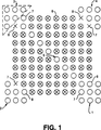
図1は、本発明の第1の実施例による二次元の、機械可読なバイナリ・コードを示す。
図2は、本発明の第2の実施例による二次元の、機械可読なバイナリ・コードを示す。
図3は、図1に示されている機械可読なバイナリ・コードの内部のコーナーの位置を決定するのに実行される典型的な処理の流れ図である。
図4は、図1に示されている機械可読なバイナリ・コードの最も外側のコーナー・ドットを決定するのに実行される典型的な処理の流れ図である。
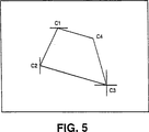
図5は、1つのコーナーの位置が決定されていない、本発明による機械可読なバイナリ・コードの概略図である。
図6は、図5の機械可読なバイナリ・コードの概略図であり、特定されていないコーナーの位置をいかにして決定するかを図解している。
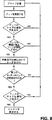
図7は、本発明によって機械可読なバイナリ・コードを復号するために実行される処理の流れ図である。
図8は、図2に示されている機械可読なバイナリ・コードの内部のコーナーの位置を決定するのに実行される処理の流れ図である。
図1を参照すると、データ・セル6の正方形のアレーすなわちマトリクスの形態を有する二次元の機械可読なバイナリ・コードが示されている。それぞれのデータは、ドットの存在又は不存在によって定義され、ドットは、「オン」であるデータ・セルを意味し、ドットの不存在は「オフ」であるデータ・セルを意味する。マトリクスの4つの限界部分のそれぞれにおけるデータ・セル1、2、3及び4の4つのグループが、コーナーを表す。それぞれのグループは、三角形の態様に配列された少なくとも6つのドット(破線で囲まれている)を含む。
図2は、図1の実施例の別の形態を示しており、マトリクスの4つのコーナーのそれぞれが、2つの「オン」のデータ・セル1、2、3及び4(破線で囲まれている)のグループによって区別される。図示されているように、「オン」であるデータ・セルのそれぞれの対の一方が、マトリクスの隣接する側面のそれぞれの対の交点に位置し、他方は、マトリクスの反対のコーナーの間に引かれた対角線上の接点の外部に位置する。
実際的な見地からすると、マトリクスのそれぞれのコーナーを定義する「オン」であるデータ・セルの数及び構成は、図1及び図2の実施例のいずれとも一致する必要はない。しかし、これらは、信頼でき容易に実現できる。「オン」のデータ・セルの数が多いほうの第1の実施例によれば、コード・リーダ(読み取り装置)は、クラッタ及び損傷の程度がより高くても許容するが、第2の実施例よりもかなり多くの処理を必要とする。
図1及び第2の実施例の両方において、マトリクスの4つのコーナーのそれぞれは、このマトリクスの4つのコーナーのそれぞれにおける2つのデータ・セル7、8によって残りの3つから一意的に識別される。データ・セル7、8の4つの対は、次のように構成されている。
主コーナー:第1のデータ・セルは「オン」、第2のデータ・セルが「オン」。
第2のコーナー:第1のデータ・セルが「オン」、第2のデータ・セルが「オフ」。
第3のコーナー:第1のデータ・セルが「オフ」、第2のデータ・セルが「オン」。
第4のコーナー:第1のデータ・セルが「オフ」、第2のデータ・セルが「オフ」。
これにより、4つのコーナーのそれぞれが相互に区別されることが可能になる。
主コーナー1と第3のコーナーとを接続する主対角線5は、コードの密度を示す「オン」のデータ・セルを含む。限定された損傷から、位置、方向及び密度情報への回復を許容する準備がなされる。

データ・セルの距離(スペーシング)は、典型的には、データ・セルの直径の半分とその全体との間であるが、変動することもあり得る。(クラッタのない)平静なエリアがそのコードを囲んでおり、典型的には、マトリクスのサイズの4分の1であるが、変動しうる。
コードは、コード読み取りに用いられる走査デバイスのオペレーティング・ソフトウェアにおいて提供される「プローブ」によって位置が特定される。これらのプローブは、走査デバイスによってピックアップされた画像のエッジに平行に延長し、内部をサーチしてコーナーを見いだす。コーナーのデータ・セルは、1つのコーナーを定義する6つのデータ・セルの中の任意の2つが欠けている(missing)場合であっても、グループを横切って移動する任意の角度のラインが少なくとも2つのデータ・セルと常に交差するように、配列される。
プローブは、画像(又は、関心領域)の左上のコーナーから開始して、コード・マトリクスの頂部(トップ)のコーナーを見つけるまで水平方向に内側に走査する。右下コーナーから開始する別のプローブが、次に、コード・マトリクスの底部(ボトム)のコーナーを見つける。2つの側面プローブが、次に、垂直方向に内側に走査する。処理を節約するために、これらは、既に頂部及び底部プローブによって定義された頂部及び底部のY座標の間のサーチに制限されている。
図1に示された本発明の実施例に対するそれぞれのコーナーの位置の処理は、図3に示された流れ図に与えられている。
図4に示された流れ図は、コーナー11における最も外側のデータ・セルの位置を決定し、プローブがコーナーとして2つのデータ・セルの位置をリターンすることが可能であることを示す。これは、マトリクスの側面がプローブに平行であるか、又は、コーナーのデータ・セルが欠けている場合に、起こりうる。すべてのコーナーの位置がいったん特定されると、それぞれのコーナーに対する最も外側のデータ・セルを決定することができる。
図2に示された実施例に対するそれぞれのコーナーの位置の処理は、図8の流れ図に与えられている。
コードがひどく歪んでいる又は伸びている場合には、1つ又は2つのコーナーの位置を特定しうる。図5は、コーナーの中の1つC4の位置が特定されていないコード・マトリクスを示す。これは、コーナーC3が底部プローブと右側プローブとの両方によって見つけられているという事実によって特徴付けられる。
「欠けている」コーナーは、その限界が2つの既知のコーナーの位置によって定義されている走査プローブによって見いだされる。2つの既知のコーナーと交差する直交するラインによって形成される点から開始して、プローブは、その限界に達するまで、第3の既知のコーナーの方向に走査する。コーナーが見つからない場合には、このプロセスは、異なるコーナーを用いて反復され、プローブの長さ、位置及び走査方向を定義する。
図5及び図6に与えられている例では、プローブは、その座標がC1の垂直位置とC3の水平位置とによって与えられ第3のコーナーC2の反対側にある点から開始する。そして、1つのデータ・セルが見つかるか又はプローブの限界がC1及びC3の位置に等しくなるまで、内側方向に走査を継続する。この例では、「欠けている」コーナーC4は、プローブによって位置が特定される。プローブは、C1からC3への対角線に平行なままであり、その限度は、C1のX位置とC3のY位置とを決して超えない。
プローブがC2及びC3と交差する直交ラインから形成されC1と反対側にある点からサーチを開始した場合には、プローブの限界(C2及びC3)に、1つのデータ・セルが見つかる前に、達してしまう可能性がある。これは、欠けているコーナーはC2とC3との間にはないことを示す。
このプロセスは、2つの欠けているコーナーの位置を特定するためにも、同様にして用いられ得る。しかし、この場合には、2つの既知のコーナーは、相互に反対側にあるものと仮定される。プローブは、欠けているコーナーが見つかるまで、既知の対角線の両側を両方の方向にサーチを行う。
それぞれのコーナーにおけるデータ・セルは、そのコーナーのデータ・セルが存在するかどうかを調べるためにチェックされる。存在しない場合には、そのコーナー・グループの残りのデータ・セルからの情報を用いて再構成される。
図1の実施例のようにそれぞれのコーナーを表すのに複数のデータ・セルが用いられる場合には、パターン・マッチング(一致)技術が、コーナーを識別するのに用いられ得る。この方法によれば、データ・セルが不存在の場合でも、コーナーを識別することが可能である。図2の実施例のように、コーナーが1対のデータ・セルによって表されているコードの場合は、損傷された又は不存在のコーナーは、システムが平行四辺形の性質を有するコードを探すように命じられる場合に、再構成が可能である。
すべてのコーナーのデータ・セルがいったん決定されると、主すなわち基準コーナーを識別することができる。プローブは、コーナーから主対角線に沿って走査を行う。それぞれのコーナーは、データ・セルの一意的(ユニーク)なシーケンスを有する。主コーナーは、特定された位置におけるデータ・セルの存在又は不存在の分析によって決定される。1つのコーナーが損傷されていながらもコードの向きを決定することもあり得る。
マトリクスの密度は、主コーナーから開始して主対角線におけるデータ・セルの数を数えることによって決定される。その両側に一定の距離を有するあるサイズよりも大きい対象物だけが有効であると考えられる。直前及び次の距離の平均の約2倍であるスペースが見いだされる場合には、データ・セルは、欠けていると想定され、対象物のカウントに含められる。
コーナーのデータ・セル位置及び密度情報を用いることにより、マトリクスを「セル」に分割するグリッドが形成される。それぞれのセルは、ドット・カラーのピクセルが一定の数(セルのサイズに比例する)より多くあるかどうかを調べるために、サンプリングされる。ある場合には、データ・セルが存在すると想定される。
コードは、幅がXデータ・セルで高さがYデータ・セルである矩形の形状を形成する、データ・セルの正方形ではないマトリクスによって表されることもある。この場合には、ユーザは、コード・マトリクスの水平及び垂直方向のデータ・セルの数を特定する。読み取りデバイスが、次に、マトリクスをセルに分割し、それを、正方マトリクスであるように復号する。
データが誤り検査(エラー・チェック)及び誤り訂正(エラー・コレクション)コードを含むこともあり得る。これによって、システムは、コードの完全性(integrity)を確認し、必要な場合には失われたデータの回復が可能になる。誤り訂正の程度は、損傷された又は部分的に欠けたコードを読み取る能力を増減させるように特定できる。与えられたサイズのマトリクスに対して、符号化された実際のデータの量は、誤り訂正能力が増加するにつれて減少する。
コードの中のデータは、純粋にバイナリ、数字(numeric)、アルファベット、英数字、パンクチュエーション(句読点等)などの多くの標準のフォーマットの中の1つに記憶される。フォーマットの使用により、使用可能なデータ・ビットの効率的な使用と符号化され得るキャラクタの範囲との間での選択が可能になる。
ユーザの定義による私的なフォーマットを、安全なコードを提供し符号化されたデータの未承認の読み取りを防止するために、設定することができる。私的なフォーマットは、標準的なフォーマットのシーケンスとして定義され、コード・マトリクスのサイズを最小化する際に、非常に有効である。例えば、例として、次のものがある。
符号化されるべきデータ:EAL:(0482)−879641
標準的なフォーマットが使用されるとすると、106ビットのデータ・フィールドが必要になる(18個の6-ビットアルファベット・キャラクタ)。
私的なフォーマットを用いると、「キー(key)」が、標準的なフォーマットのシーケンスとして定義される。このキーは、ストリングにおけるそれぞれのキャラクタがどのフォーマットで符号化されるかをシステムに告げる。上の例では、キーは、222424111144111111として定義されるが、これは、最初の3つのキャラクタはフォーマット2であり、次がフォーマット4であり、…、最後のキャラクタはフォーマット1である、ことを意味する。このデータは、この場合には、76ビットを必要とするにすぎない。更に、正しいキーがなければ、情報は、完全には、復号できない。
コードのある主の変更されたものも読み出せるように、準備がなされる。すなわち、
1.コードの鏡映画像(mirrored image)。
2.明るい背景上での暗いドットに加えて、暗い背景上での明るいドット。
システムの処理速度を向上させるために、ユーザが特定することができる種々のオプションがある。例えば、次の通りである。
1.コードの周囲にクラッタはないとする。その場合には、プローブは、任意のサイズの交差が生じるのを探す。これにより、コーナーの位置が決定される。
2.関心領域(処理ウィンドウ)を、その領域内だけでサーチが行われるように、設定する。
3.コードが平行四辺形であると想定する。すると、1つのコーナーが見つからない場合であっても、セル・サンプリング・グリッドを、「欠けている」コーナーを見つける必要なく、形成することができる。
4.コーナー・グループからドットが1つだけ欠けることを許容する。これにより、コーナーの完全性の分析が、より少数の変動に限定される。
5.コードの向きが既知とする。すると、主コーナーの相対的位置を決定する必要がなくなる。
6.マトリクスの密度が既知とする。すると、主対角線をサンプリングして、その長さに沿ったドットの数を求める必要がなくなる。
7.それぞれのセルの中心のピクセルだけをサンプリングして、ドットが存在するかどうかを判断する。The present invention relates to a binary code that can be read optically by a machine and used on goods for identification purposes. More particularly, the present invention relates to machine-readable binary code composed of a two-dimensional matrix or array of data cells.
The use of barcodes to identify a wide range of goods and products is widely known. The bar code is composed of a large number of bar lines (bars) having various widths arranged such that the side surfaces are aligned in the linear direction. To determine the meaning of a bar code, the bar code must be scanned in a direction substantially parallel to the linear direction of the bar. This means that the barcode has a preferred scanning direction and the scanning device used to read the barcode must be able to scan in this direction. Bar codes must be properly oriented for scanning, so they must be oriented in advance when presented to the scanning machine, otherwise the scanning machine can scan in many different directions. Must have the ability.
Bar codes enjoy use in a wide range of applications. However, barcodes are generally not considered appropriate for applications where space is limited. The reason is that it is impossible to barcode a large amount of information reliably in a small usable space.
This limitation has led to the development of two-dimensional codes for data encryption and encoding.
There are two basic types of known two-dimensional codes. One type is based on traditional barcode technology in that it includes a row of barcodes arranged such that another barcode is superimposed on one barcode. At this time, there may or may not be additional lines to separate the rows. The best known examples of this type of code are those referred to by the names Code 49, Code 16K, CODABLOCK, and PDF 417. These codes do not represent a significant change from the barcode technology because both the printing and reading devices are the same or very similar. They also suffer from some of the limitations associated with barcodes. For example, Code 49 and Code 16K both have a fixed row length and are limited in the number of rows. As a result, the amount of data that can be encoded given the actual physical size of the code is limited. Furthermore, in the case of barcodes, this type of code can only be read in a fixed direction.
The other type is a matrix code, among which a data matrix (Data Matrix), USD-5, or Vericode is well known. These codes are generally readable only when using cameras and image identification systems.
Data carrying the capacity of the matrix code varies from type to type. Data Matrix (Data Matrix) by International Data Matrix in the US can encode ISO characters up to 500 ASCII. Vericode, developed and patented by Veritec of the United States, can print in multiple formats, one of which can encode up to 2000 characters. USD-5 by Swedish company Baumer Ident is a low density code that can encode up to 64 decimal digits. However, this code can be read in any direction, but its matrix density is fixed, limiting its flexibility.
The data code and the vericode have the form of a square matrix of binary data cells (square matrix), with clear boundaries that include code direction and timing (ie, density) information. Both of these codes can dynamically change their density and size without having to reconfigure the system again. However, both of these codes are considered inappropriate for applications in the leather and textile industries that need to take the form of holes punched into the article or product in which the data cells that make up the code are encoded. ing. Both codes require clear boundaries that provide code direction and timing information. As a result, they either fall or, at best, are subject to a high risk of tearing or cord damage when used in leather and fiber applications.
In addition, data codes and verify codes are also very intolerant with respect to misalignment of data cells and can only handle minimal stretching and distortion. In order to be essentially readable, the code matrix must retain the parallelogram shape. There are many applications where the code is distorted in use and therefore cannot meet this requirement.
Examining these known two-dimensional codes, it can be concluded that all have drawbacks and limitations in the following areas. That is,
1) Robustness (consistent identification of current code)
2) Processing speed converted to actual throughput for online applications 3) Consistent readability using low cost inkjet printed code 4) Use of holes instead of ink printing to represent data cells 5) Consistent reading of distorted codes None of the known 2D codes meet all of these requirements.
It is an object of the present invention to provide machine readable binary code that allows each corner of a symbol that embodies the code to be identifiable by a code reading machine, and that each corner is distinguishable from each other. Is to provide.
It is an object of the present invention to provide machine readable binary code that does not require the presence of a clear boundary that provides direction and timing information for the reading machine.
It is a further object of the present invention to provide a machine readable binary code that allows the position, orientation and distortion of symbols to be easily calculated. In this way, the readability of the code is not lost by symbol expansion or distortion.
In accordance with the present invention, a machine-readable binary code having a two-dimensional matrix of data cells having a plurality of sides, wherein a unique sub-array of data cells is at the intersection of each pair of adjacent sides. A machine-readable binary code is provided that is positioned to define and uniquely identify each corner of the matrix.
Typically, the matrix has four sides and takes the form of a square or rectangle. However, the present invention can also be applied to a matrix having any polygonal shape, such as a triangle, octagon, or parallelogram, depending on the specific requirements.
In one embodiment of the present invention, each sub-array is in a triangle of “on” cells that form the actual corners of the matrix, and a sub-array that uniquely identifies each corner from the remaining three. Defined by a combination of "on" and "off" cells formed by two data cells. An “on” cell is a positively readable cell, such as a dot printed to be marked on an article or product or a hole punched in the surface above it.
In another embodiment of the invention, each sub-array includes a group of four data cells, two of which are always “on” and define one corner of the matrix. Two of them function to uniquely identify the corner from the remaining three. Preferably, one of the two “on” data cells that function to define each corner of the matrix is located at the intersection of each pair of adjacent sides of the matrix and the other is the first one Adjacent to and outside the intersection.
The array of two data cells from each sub-array to uniquely identify each corner from the remaining three corners is as follows:
Main (principal) corner: the first data cell is “on”, the second data cell is also “on”,
Second corner: the first data cell is “on”, the second data cell is “off”,
Third corner: the first data cell is “off”, the second data cell is “on”,
Fourth corner: the first data cell is “off” and the second data cell is also “off”,
Both embodiments of the present invention provide a useful alternative to the known matrix code described above.
The first allows the reading machine to tolerate a higher degree of clutter and symbol damage, but requires significantly longer processing times than the latter.
Determining the relative direction angle of the symbol relative to the reading machine is a comparison, since each of the four corners of the symbol on which a two-dimensional machine readable binary code is implemented can be uniquely identified. Easy.
The number of “on” and “off” data cells present in each sub-array allows each of the four corners of the symbol to be uniquely identified, as well as the relative of each sub-array. It is also possible to identify each of the four corners from a specific direction. The significance of this is that it is possible to determine which corner hits which, even if “on” data cells do not exist or are not found due to distortion.
The density of the matrix, ie the number of data cells, can easily be determined by counting the number of data cells in the main (leading) diagonal extending from the main or reference corner to the opposite corner of the array. To ensure read accuracy, all data cells in the main diagonal are “on”.
The two-dimensional machine-readable binary code according to the present invention can be printed on an article or product using various techniques such as etching, ink printing or punching. Importantly, no boundaries are required around internal data fields to facilitate direction and / or timing, so symbols will fall outside the code or even break the code at best Or it can punch symbols on an article or product without causing any risk of damage.
Embodiments of the present invention will now be described by reference to the accompanying drawings.
FIG. 1 shows a two-dimensional, machine-readable binary code according to a first embodiment of the invention.
FIG. 2 shows a two-dimensional, machine-readable binary code according to a second embodiment of the present invention.
FIG. 3 is a flowchart of an exemplary process performed to determine the location of the internal corners of the machine readable binary code shown in FIG.
FIG. 4 is a flowchart of an exemplary process performed to determine the outermost corner dot of the machine readable binary code shown in FIG.
FIG. 5 is a schematic diagram of a machine-readable binary code according to the present invention in which the position of one corner has not been determined.
FIG. 6 is a schematic diagram of the machine-readable binary code of FIG. 5, illustrating how to determine the location of unspecified corners.
FIG. 7 is a flowchart of the processing performed to decode machine-readable binary code according to the present invention.
FIG. 8 is a flow diagram of the processing performed to determine the location of the internal corners of the machine readable binary code shown in FIG.
Referring to FIG. 1, a two-dimensional machine readable binary code having the form of a square array or matrix of data cells 6 is shown. Each data is defined by the presence or absence of a dot, where a dot means a data cell that is “on” and a absence of a dot means a data cell that is “off”. Four groups of data cells 1, 2, 3, and 4 in each of the four limit parts of the matrix represent corners. Each group includes at least six dots (surrounded by a broken line) arranged in a triangular manner.
FIG. 2 shows another form of the embodiment of FIG. 1, where each of the four corners of the matrix is surrounded by two “on” data cells 1, 2, 3, and 4 (dashed lines). ) Group. As shown, one of each pair of data cells that is “on” is located at the intersection of each pair of adjacent sides of the matrix, and the other is drawn between opposite corners of the matrix. Located outside the diagonal contact.
From a practical standpoint, the number and configuration of “on” data cells defining each corner of the matrix need not match any of the embodiments of FIGS. However, these can be realized reliably and easily. According to the first embodiment with the larger number of “on” data cells, the code reader allows a higher degree of clutter and damage, but the second embodiment. Requires significantly more processing.
In both FIG. 1 and the second embodiment, each of the four corners of the matrix is uniquely identified from the remaining three by the two
Main corner: The first data cell is “on” and the second data cell is “on”.
Second corner: the first data cell is “on” and the second data cell is “off”.
Third corner: the first data cell is “off” and the second data cell is “on”.
Fourth corner: the first data cell is “off” and the second data cell is “off”.
This allows each of the four corners to be distinguished from each other.
The main diagonal line 5 connecting the main corner 1 and the third corner contains "on" data cells indicating the density of the code. Preparations are made to allow recovery from limited damage to position, orientation and density information.
The distance (spacing) of a data cell is typically between half the data cell diameter and the whole, but can vary. A quiet area (without clutter) surrounds the code and is typically a quarter of the size of the matrix, but can vary.
The code is located by a “probe” provided in the operating software of the scanning device used for code reading. These probes extend parallel to the edge of the image picked up by the scanning device and search the interior to find corners. A corner data cell has at least a line of any angle that moves across the group, even if any two of the six data cells that define a corner are missing. Arranged to always intersect two data cells.
The probe starts in the upper left corner of the image (or region of interest) and scans inward horizontally until it finds the top corner of the code matrix. Another probe starting from the lower right corner then finds the bottom corner of the code matrix. The two side probes then scan inward in the vertical direction. In order to save processing, they are limited to searching between the top and bottom Y coordinates already defined by the top and bottom probes.
The processing of the location of each corner for the embodiment of the invention shown in FIG. 1 is given in the flow diagram shown in FIG.
The flowchart shown in FIG. 4 determines the position of the outermost data cell at corner 11 and shows that the probe can return the position of the two data cells as a corner. This can occur if the side of the matrix is parallel to the probe or if corner data cells are missing. Once all corner locations have been identified, the outermost data cell for each corner can be determined.
The processing of the location of each corner for the embodiment shown in FIG. 2 is given in the flowchart of FIG.
If the cord is severely distorted or stretched, the location of one or two corners can be identified. FIG. 5 shows a code matrix in which the position of one C4 in the corner is not specified. This is characterized by the fact that corner C3 is found by both the bottom probe and the right probe.
“Missing” corners are found by scanning probes whose limits are defined by the positions of two known corners. Starting from a point formed by orthogonal lines intersecting two known corners, the probe scans in the direction of the third known corner until it reaches its limit. If no corner is found, this process is repeated with different corners to define the probe length, position and scan direction.
In the example given in FIGS. 5 and 6, the probe starts from the point whose coordinates are given by the vertical position of C1 and the horizontal position of C3 and are opposite the third corner C2. The scanning is then continued inward until one data cell is found or the probe limit is equal to the position of C1 and C3. In this example, the “missing” corner C4 is located by the probe. The probe remains parallel to the diagonal from C1 to C3, and its limits never exceed the X position of C1 and the Y position of C3.
If the probe is started from a point formed by an orthogonal line intersecting C2 and C3 and on the opposite side of C1, the probe limit (C2 and C3) is reached before one data cell is found. There is a possibility that. This indicates that there are no missing corners between C2 and C3.
This process can be used in a similar manner to locate the two missing corners. However, in this case it is assumed that the two known corners are on opposite sides of each other. The probe searches in both directions on both sides of the known diagonal until a missing corner is found.
The data cell at each corner is checked to see if there is a data cell for that corner. If not, it is reconstructed using information from the remaining data cells in that corner group.
If multiple data cells are used to represent each corner, as in the embodiment of FIG. 1, pattern matching techniques can be used to identify the corners. According to this method, it is possible to identify a corner even when there is no data cell. In the case of a code in which corners are represented by a pair of data cells, as in the embodiment of FIG. 2, a damaged or absent corner will cause the system to look for codes with parallelogram properties. Reconfiguration is possible if commanded to.
Once all corner data cells have been determined, the main or reference corner can be identified. The probe scans from the corner along the main diagonal. Each corner has a unique sequence of data cells. The main corner is determined by an analysis of the presence or absence of a data cell at the specified location. It is possible to determine the orientation of the cord while one corner is damaged.
The density of the matrix is determined by counting the number of data cells in the main diagonal starting from the main corner. Only objects larger than a certain size with a certain distance on both sides are considered effective. If a space is found that is about twice the average of the previous and next distances, the data cell is assumed to be missing and is included in the object count.
By using the corner data cell location and density information, a grid is formed that divides the matrix into "cells". Each cell is sampled to see if there are more than a certain number of dot color pixels (proportional to the size of the cell). In some cases, a data cell is assumed to exist.
The code may be represented by a non-square matrix of data cells that forms a rectangular shape that is X data cells wide and Y data cells high. In this case, the user specifies the number of data cells in the horizontal and vertical directions of the code matrix. A reading device then divides the matrix into cells and decodes it to be a square matrix.
It is possible that the data includes error checking (error checking) and error correcting (error collection) codes. This allows the system to check the integrity of the code and recover lost data if necessary. The degree of error correction can be specified to increase or decrease the ability to read damaged or partially missing codes. For a given size matrix, the amount of actual data encoded decreases as error correction capability increases.
The data in the code is stored in one of many standard formats such as purely binary, numeric, alphabetic, alphanumeric, punctuation (punctuation marks, etc.). The use of the format allows a choice between the efficient use of the available data bits and the range of characters that can be encoded.
A user-defined private format can be set to provide a secure code and prevent unauthorized reading of the encoded data. A private format is defined as a sequence of standard formats and is very useful in minimizing the size of the code matrix. For example, there are the following:
Data to be encoded: EAL: (0482) -889641
If a standard format is used, a 106-bit data field is required (18 6-bit alphabet characters).
Using a private format, a "key" is defined as a standard format sequence. This key tells the system in which format each character in the string is encoded. In the above example, the key is defined as 2224241111144111111, which means that the first three characters are format 2, the next is format 4, ..., the last character is format 1 To do. This data in this case only requires 76 bits. Furthermore, without the correct key, the information cannot be completely decrypted.
Preparations are made so that the main modified version of the code can also be read. That is,
1. Mirrored image of the code.
2. Bright dots on a dark background in addition to dark dots on a light background.
There are various options that can be specified by the user to improve the processing speed of the system. For example:
1. Assume that there is no clutter around the cord. In that case, the probe looks for any size crossings to occur. Thereby, the position of the corner is determined.
2. Set the region of interest (processing window) so that the search is performed only within that region.
3. Assume that the code is a parallelogram. Then, even if one corner is not found, the cell sampling grid can be formed without having to find the “missing” corner.
4. Allow only one dot to be missing from a corner group. This limits the corner integrity analysis to fewer variations.
5. The direction of the code is assumed to be known. Then, it is not necessary to determine the relative position of the main corner.
6. The density of the matrix is assumed to be known. This eliminates the need to sample the main diagonal and determine the number of dots along that length.
7. Sample only the center pixel of each cell to determine if a dot exists.
Claims (9)
データ・セルを構成要素とするサブアレー(1、2、3、4、7、8)が、前記交点のそれぞれに提供され、
前記サブアレー(1、2、3、4、7、8)は、それぞれが、データ・セルの第1のグループ(1、2、3、4)とデータ・セルの第2のグループ(7、8)とで構成され、
前記データ・セルの第1のグループ(1、2、3、4)の構成は、それぞれのサブアレー(1、2、3、4、7、8)で同一であり、
前記データ・セルの第1のグループ(1、2、3、4)は、それぞれが、コーナーの存在を示すものとして読取装置による認識が可能であって特徴的なパターンを有する「オン」のデータ・セルで構成され、
前記データ・セルの第2のグループ(7、8)の構成は、それぞれのサブアレー(1、2、3、4、7、8)で異なり、
前記データ・セルの第2のグループ(7、8)は、それぞれが、対応する前記データ・セルの第1のグループ(1、2、3、4)と前記マトリクスの残りの部分との間に位置し、前記マトリクスのそれぞれのコーナーをそれ以外のコーナーから一意的に識別するものとして読取装置によって認識可能であることを特徴とする機械可読なバイナリ・コード。A machine-readable binary code composed of a two-dimensional matrix having data cells (6) as a component, wherein the matrix is composed of a main array having data cells as components, and the main array is mutually Extending in first and second directions perpendicular to the matrix, the matrix having a plurality of connecting side surfaces formed by data cells extending around the main array, the side surfaces adjacent to each other being In machine-readable binary code that matches at the intersection,
Subarrays (1, 2, 3, 4, 7, 8) comprising data cells as components are provided at each of the intersection points,
The subarrays (1, 2, 3, 4, 7, 8) each have a first group of data cells (1, 2, 3, 4) and a second group of data cells (7, 8). ) And
The configuration of the first group of data cells (1, 2, 3, 4) is the same in each sub-array (1, 2, 3, 4, 7, 8);
Each of the first group of data cells (1, 2, 3, 4) is “ON” data having a characteristic pattern that can be recognized by the reader as indicating the presence of a corner.・ It consists of cells,
The configuration of the second group of data cells (7, 8) is different for each sub-array (1, 2, 3, 4, 7, 8),
The second group of data cells (7, 8) is each between a corresponding first group of data cells (1, 2, 3, 4) and the rest of the matrix. A machine-readable binary code that is positioned and recognizable by a reader as uniquely identifying each corner of the matrix from the other corners.
主コーナーは、第1のデータ・セルが「オン」であり、第2のデータ・セルも「オン」であり、
第2のコーナーは、第1のデータ・セルが「オン」であり、第2のデータ・セルが「オフ」であり、
第3のコーナーは、第1のデータ・セルが「オフ」であり、第2のデータ・セルが「オン」であり、
第4のコーナーは、第1のデータ・セルが「オフ」であり、第2のデータ・セルも「オフ」であるものとして、残りの3つのコーナーから一意的に識別することを特徴とする機械可読なバイナリ・コード。6. The machine readable binary code according to claim 4 or claim 5, wherein two data cells from each of the second group have respective corners in the four corners,
The main corner is that the first data cell is “on”, the second data cell is “on”,
The second corner is when the first data cell is “on”, the second data cell is “off”,
The third corner is that the first data cell is “off”, the second data cell is “on”,
The fourth corner is uniquely identified from the remaining three corners, assuming that the first data cell is “off” and the second data cell is also “off”. Machine-readable binary code.
前記コードを光学的に走査するステップと、
パターン・マッチング技術を用いてそれぞれのサブアレーにおける前記データ・セルの第1のグループ(1、2、3、4)を検出するステップと、
前記第1のグループの存在によって1つのサブアレーを検出し、当該サブアレーの同一性(アイデンティティ)を、特定の位置における前記データ・セルの第2のグループ(7、8)に対する走査により決定するステップと、
を含むことを特徴とする方法。A method for detecting and identifying a corner of a machine-readable binary code according to any one of claims 1 to 7, comprising:
Optically scanning the code;
Detecting a first group (1, 2, 3, 4) of the data cells in each sub-array using pattern matching techniques;
Detecting a sub-array by the presence of the first group and determining the identity of the sub-array by scanning the second group (7, 8) of the data cells at a specific location; ,
A method comprising the steps of:
イメージ捕捉手段と、
捕捉されたイメージを処理し、それぞれのサブアレーのデータ・セルの第1のグループ(1、2、3、4)を検出することにより前記機械可読なバイナリ・コードのそれぞれのコーナーを検出し、特定の位置にあるデータ・セルの第2のグループ(7、8)を走査することによりそれぞれのコーナーをそれ以外のコーナーから区別する手段と、
を備えていることを特徴とするバイナリ・コード読取装置。A binary code reader for use with the machine readable binary code of any one of claims 1 to 7, comprising:
Image capturing means;
Detect and identify each corner of the machine-readable binary code by processing the captured image and detecting the first group (1, 2, 3, 4) of each subarray data cell Means for distinguishing each corner from the other corners by scanning a second group of data cells (7, 8) at
A binary code reader characterized by comprising:
Applications Claiming Priority (3)
| Application Number | Priority Date | Filing Date | Title |
|---|---|---|---|
| GB9408626.1 | 1994-04-29 | ||
| GB9408626A GB9408626D0 (en) | 1994-04-29 | 1994-04-29 | Machine readable binary code |
| PCT/GB1995/000936 WO1995030206A1 (en) | 1994-04-29 | 1995-04-25 | Machine readable binary codes |
Publications (2)
| Publication Number | Publication Date |
|---|---|
| JPH10503304A JPH10503304A (en) | 1998-03-24 |
| JP4183275B2 true JP4183275B2 (en) | 2008-11-19 |
Family
ID=10754391
Family Applications (1)
| Application Number | Title | Priority Date | Filing Date |
|---|---|---|---|
| JP52805095A Expired - Fee Related JP4183275B2 (en) | 1994-04-29 | 1995-04-25 | Machine-readable binary code |
Country Status (7)
| Country | Link |
|---|---|
| US (1) | US5825015A (en) |
| EP (1) | EP0757823B1 (en) |
| JP (1) | JP4183275B2 (en) |
| AT (1) | ATE167941T1 (en) |
| DE (1) | DE69503240T2 (en) |
| GB (1) | GB9408626D0 (en) |
| WO (1) | WO1995030206A1 (en) |
Families Citing this family (45)
| Publication number | Priority date | Publication date | Assignee | Title |
|---|---|---|---|---|
| JP3448120B2 (en) * | 1994-12-27 | 2003-09-16 | シャープ株式会社 | Digital information record carrier |
| US20030203390A1 (en) * | 1995-10-26 | 2003-10-30 | Kaye Paul H. | Coded particles for process sequence tracking in combinatorial compound library preparation |
| US20020084329A1 (en) * | 1997-07-16 | 2002-07-04 | Kaye Paul H. | Coded items for labeling objects |
| US6267296B1 (en) * | 1998-05-12 | 2001-07-31 | Denso Corporation | Two-dimensional code and method of optically reading the same |
| US6674919B1 (en) | 1999-09-21 | 2004-01-06 | Matsushita Electric Industrial Co., Ltd. | Method for determining the skew angle of a two-dimensional barcode |
| DE60118051T2 (en) * | 2000-04-06 | 2006-08-31 | Seiko Epson Corp. | Method and apparatus for reading a two-dimensional bar code and data storage medium |
| GB0009719D0 (en) * | 2000-04-19 | 2000-06-07 | Scient Generics Ltd | A method of fabricating coded particles |
| EP1360640B1 (en) * | 2001-02-09 | 2006-05-10 | Enseal Systems Limited | Document printed with graphical symbols which encode information |
| US6869022B2 (en) * | 2001-06-29 | 2005-03-22 | General Electric Company | Computer-and human-readable part markings and system and method using same |
| JP2003058841A (en) * | 2001-08-09 | 2003-02-28 | Satoshi Mizoguchi | Two-dimensional code |
| WO2003025845A1 (en) * | 2001-09-17 | 2003-03-27 | Codemagic | Machine-readable symbol and related method |
| DE10220220C1 (en) * | 2002-02-18 | 2003-05-22 | Tropf Hermann | Localization device for optically-readable code or text uses localization pattern with at least four 2-dimensional elements of 2 different types |
| US6959866B2 (en) * | 2002-05-30 | 2005-11-01 | Ricoh Company, Ltd. | 2-Dimensional code pattern, 2-dimensional code pattern supporting medium, 2-dimensional code pattern generating method, and 2-dimensional code reading apparatus and method |
| JP4547578B2 (en) | 2002-07-08 | 2010-09-22 | ベリテック インコーポレーテッド | Method for reading a symbol having encoded information |
| US7430497B2 (en) * | 2002-10-31 | 2008-09-30 | Microsoft Corporation | Statistical model for global localization |
| US7116840B2 (en) * | 2002-10-31 | 2006-10-03 | Microsoft Corporation | Decoding and error correction in 2-D arrays |
| US7502507B2 (en) * | 2002-10-31 | 2009-03-10 | Microsoft Corporation | Active embedded interaction code |
| US7133563B2 (en) | 2002-10-31 | 2006-11-07 | Microsoft Corporation | Passive embedded interaction code |
| US7465342B2 (en) * | 2003-04-07 | 2008-12-16 | Silverbrook Research Pty Ltd | Method of minimizing absorption of visible light in ink compositions comprising infrared metal-dithiolene dyes |
| US7583842B2 (en) | 2004-01-06 | 2009-09-01 | Microsoft Corporation | Enhanced approach of m-array decoding and error correction |
| US7263224B2 (en) | 2004-01-16 | 2007-08-28 | Microsoft Corporation | Strokes localization by m-array decoding and fast image matching |
| ATE497219T1 (en) | 2004-10-15 | 2011-02-15 | Sony Computer Entertainment Inc | MAP AND IMAGE DATA TRANSMISSION METHOD |
| US7607076B2 (en) | 2005-02-18 | 2009-10-20 | Microsoft Corporation | Embedded interaction code document |
| US7826074B1 (en) | 2005-02-25 | 2010-11-02 | Microsoft Corporation | Fast embedded interaction code printing with custom postscript commands |
| US7599560B2 (en) | 2005-04-22 | 2009-10-06 | Microsoft Corporation | Embedded interaction code recognition |
| US7421439B2 (en) | 2005-04-22 | 2008-09-02 | Microsoft Corporation | Global metadata embedding and decoding |
| US7412089B2 (en) * | 2005-05-23 | 2008-08-12 | Nextcode Corporation | Efficient finder patterns and methods for application to 2D machine vision problems |
| US7400777B2 (en) | 2005-05-25 | 2008-07-15 | Microsoft Corporation | Preprocessing for information pattern analysis |
| US7729539B2 (en) | 2005-05-31 | 2010-06-01 | Microsoft Corporation | Fast error-correcting of embedded interaction codes |
| US7580576B2 (en) | 2005-06-02 | 2009-08-25 | Microsoft Corporation | Stroke localization and binding to electronic document |
| US7619607B2 (en) | 2005-06-30 | 2009-11-17 | Microsoft Corporation | Embedding a pattern design onto a liquid crystal display |
| US7622182B2 (en) | 2005-08-17 | 2009-11-24 | Microsoft Corporation | Embedded interaction code enabled display |
| US7817816B2 (en) | 2005-08-17 | 2010-10-19 | Microsoft Corporation | Embedded interaction code enabled surface type identification |
| US8789756B2 (en) | 2006-02-25 | 2014-07-29 | Roche Diagnostics Operations, Inc. | Test element coding apparatuses, systems and methods |
| EP1826705A1 (en) | 2006-02-25 | 2007-08-29 | F.Hoffmann-La Roche Ag | Analytical consumables and arrangement for reading information |
| US8050502B2 (en) * | 2006-06-21 | 2011-11-01 | Namco Bandai Games Inc. | Two-Dimensional code generation method, two-dimensional code, two-dimensional code recognition method, and image recognition device |
| WO2008134804A1 (en) * | 2007-05-03 | 2008-11-13 | Kevin Loughrey | Large number id tagging system |
| GB0725306D0 (en) * | 2007-12-28 | 2008-02-06 | Pronostics Ltd | Improved microparticles |
| KR101801217B1 (en) | 2012-11-13 | 2017-11-24 | 교도 인사쯔 가부시키가이샤 | Two-dimensional code |
| JP6261118B2 (en) * | 2013-12-09 | 2018-01-17 | 眞理子 溝口 | Two-dimensional code reading method and recording medium for the two-dimensional code |
| JP2017191420A (en) * | 2016-04-13 | 2017-10-19 | 溝口 さとし | Two-dimensional code storage medium and two-dimensional code reading method |
| JP6810940B2 (en) * | 2019-04-10 | 2021-01-13 | ソノー電機工業株式会社 | Two-dimensional code, recognition processing program, recognition processing device, and recognition processing method |
| JP7251283B2 (en) * | 2019-04-16 | 2023-04-04 | 大日本印刷株式会社 | Two-dimensional code, method of forming two-dimensional code, printed matter and package printed with two-dimensional code |
| US11314997B1 (en) | 2020-04-18 | 2022-04-26 | Rf Code, Inc. | Barcode tag, and method and system employing same, for tracking electronic equipment |
| WO2023158854A2 (en) | 2022-02-21 | 2023-08-24 | Rf Code, Inc. | System, apparatus, and method for monitoring edge compute sites |
Family Cites Families (4)
| Publication number | Priority date | Publication date | Assignee | Title |
|---|---|---|---|---|
| EP0299383B1 (en) * | 1987-07-11 | 1994-11-23 | Hirokazu Yoshida | Method of reading identification code sheets |
| US4924078A (en) * | 1987-11-25 | 1990-05-08 | Sant Anselmo Carl | Identification symbol, system and method |
| US5202552A (en) * | 1991-04-22 | 1993-04-13 | Macmillan Bloedel Limited | Data with perimeter identification tag |
| US5288986A (en) * | 1992-09-17 | 1994-02-22 | Motorola, Inc. | Binary code matrix having data and parity bits |
-
1994
- 1994-04-29 GB GB9408626A patent/GB9408626D0/en active Pending
-
1995
- 1995-04-25 AT AT95916759T patent/ATE167941T1/en not_active IP Right Cessation
- 1995-04-25 EP EP95916759A patent/EP0757823B1/en not_active Expired - Lifetime
- 1995-04-25 WO PCT/GB1995/000936 patent/WO1995030206A1/en active IP Right Grant
- 1995-04-25 DE DE69503240T patent/DE69503240T2/en not_active Expired - Fee Related
- 1995-04-25 JP JP52805095A patent/JP4183275B2/en not_active Expired - Fee Related
- 1995-04-25 US US08/722,083 patent/US5825015A/en not_active Expired - Fee Related
Also Published As
| Publication number | Publication date |
|---|---|
| JPH10503304A (en) | 1998-03-24 |
| EP0757823B1 (en) | 1998-07-01 |
| DE69503240T2 (en) | 1999-02-18 |
| GB9408626D0 (en) | 1994-06-22 |
| WO1995030206A1 (en) | 1995-11-09 |
| DE69503240D1 (en) | 1998-08-06 |
| EP0757823A1 (en) | 1997-02-12 |
| US5825015A (en) | 1998-10-20 |
| ATE167941T1 (en) | 1998-07-15 |
Similar Documents
| Publication | Publication Date | Title |
|---|---|---|
| JP4183275B2 (en) | Machine-readable binary code | |
| US7181066B1 (en) | Method for locating bar codes and symbols in an image | |
| US5304787A (en) | Locating 2-D bar codes | |
| US5814801A (en) | Maxicode data extraction using spatial domain features exclusive of fourier type domain transfer processing | |
| CN1031772C (en) | Decoding method of two-dimensional code symbol mark | |
| EP1016027B1 (en) | Distortion resistant double-data correcting color transition barcode and method of generating and using same | |
| US5464974A (en) | Dynamically variable machine readable binary code and method for reading and producing thereof | |
| JP3526880B2 (en) | Multi-resolution machine readable symbol | |
| US6631843B2 (en) | Composite code symbology | |
| US6742708B2 (en) | Fiducial mark patterns for graphical bar codes | |
| US6758399B1 (en) | Distortion correction method in optical code reading | |
| EP0336778A2 (en) | Polygonal information decoding process and apparatus | |
| US20100044445A1 (en) | Method and System for Creating and Using Barcodes | |
| EP0336769A2 (en) | Hexagonal information encoding article, process and system | |
| EP0585244A1 (en) | Data tag and detecting method | |
| US5126542A (en) | Dynamically variable machine readable binary code and method for reading and producing thereof | |
| Hahn et al. | Implementation of algorithm to decode two-dimensional barcode PDF-417 | |
| CN102081747A (en) | Two-dimensional bar code | |
| US8226010B2 (en) | Blur resistant barcode | |
| CN101882204B (en) | Matrix type two-dimensional bar code searching method | |
| US6761314B2 (en) | Bar code symbology for consumer scanning applications | |
| JP2007511342A (en) | Video coding method and apparatus using parity check matrix | |
| WO2012035552A2 (en) | Generating a code system using haar wavelets | |
| JP2017510132A (en) | Simple encoding, authentication and copy detection system for printed documents | |
| CN118140228A (en) | Label and method and system for automatic product identification |
Legal Events
| Date | Code | Title | Description |
|---|---|---|---|
| A131 | Notification of reasons for refusal |
Free format text: JAPANESE INTERMEDIATE CODE: A131 Effective date: 20041130 |
|
| A601 | Written request for extension of time |
Free format text: JAPANESE INTERMEDIATE CODE: A601 Effective date: 20050225 |
|
| A602 | Written permission of extension of time |
Free format text: JAPANESE INTERMEDIATE CODE: A602 Effective date: 20050411 |
|
| A521 | Request for written amendment filed |
Free format text: JAPANESE INTERMEDIATE CODE: A523 Effective date: 20050531 |
|
| A02 | Decision of refusal |
Free format text: JAPANESE INTERMEDIATE CODE: A02 Effective date: 20050802 |
|
| A521 | Request for written amendment filed |
Free format text: JAPANESE INTERMEDIATE CODE: A523 Effective date: 20051130 |
|
| A911 | Transfer to examiner for re-examination before appeal (zenchi) |
Free format text: JAPANESE INTERMEDIATE CODE: A911 Effective date: 20060126 |
|
| A912 | Re-examination (zenchi) completed and case transferred to appeal board |
Free format text: JAPANESE INTERMEDIATE CODE: A912 Effective date: 20060202 |
|
| A01 | Written decision to grant a patent or to grant a registration (utility model) |
Free format text: JAPANESE INTERMEDIATE CODE: A01 |
|
| A61 | First payment of annual fees (during grant procedure) |
Free format text: JAPANESE INTERMEDIATE CODE: A61 Effective date: 20080902 |
|
| FPAY | Renewal fee payment (event date is renewal date of database) |
Free format text: PAYMENT UNTIL: 20110912 Year of fee payment: 3 |
|
| R150 | Certificate of patent or registration of utility model |
Free format text: JAPANESE INTERMEDIATE CODE: R150 |
|
| LAPS | Cancellation because of no payment of annual fees |