JP4181997B2 - Gas flow distributor for side airbag module - Google Patents
Gas flow distributor for side airbag module Download PDFInfo
- Publication number
- JP4181997B2 JP4181997B2 JP2003559820A JP2003559820A JP4181997B2 JP 4181997 B2 JP4181997 B2 JP 4181997B2 JP 2003559820 A JP2003559820 A JP 2003559820A JP 2003559820 A JP2003559820 A JP 2003559820A JP 4181997 B2 JP4181997 B2 JP 4181997B2
- Authority
- JP
- Japan
- Prior art keywords
- gas
- gas flow
- flow distributor
- generator
- holding
- Prior art date
- Legal status (The legal status is an assumption and is not a legal conclusion. Google has not performed a legal analysis and makes no representation as to the accuracy of the status listed.)
- Expired - Fee Related
Links
Images


Classifications
-
- B—PERFORMING OPERATIONS; TRANSPORTING
- B60—VEHICLES IN GENERAL
- B60R—VEHICLES, VEHICLE FITTINGS, OR VEHICLE PARTS, NOT OTHERWISE PROVIDED FOR
- B60R21/00—Arrangements or fittings on vehicles for protecting or preventing injuries to occupants or pedestrians in case of accidents or other traffic risks
- B60R21/02—Occupant safety arrangements or fittings, e.g. crash pads
- B60R21/16—Inflatable occupant restraints or confinements designed to inflate upon impact or impending impact, e.g. air bags
- B60R21/26—Inflatable occupant restraints or confinements designed to inflate upon impact or impending impact, e.g. air bags characterised by the inflation fluid source or means to control inflation fluid flow
- B60R21/261—Inflatable occupant restraints or confinements designed to inflate upon impact or impending impact, e.g. air bags characterised by the inflation fluid source or means to control inflation fluid flow with means other than bag structure to diffuse or guide inflation fluid
-
- B—PERFORMING OPERATIONS; TRANSPORTING
- B60—VEHICLES IN GENERAL
- B60R—VEHICLES, VEHICLE FITTINGS, OR VEHICLE PARTS, NOT OTHERWISE PROVIDED FOR
- B60R21/00—Arrangements or fittings on vehicles for protecting or preventing injuries to occupants or pedestrians in case of accidents or other traffic risks
- B60R21/02—Occupant safety arrangements or fittings, e.g. crash pads
- B60R21/16—Inflatable occupant restraints or confinements designed to inflate upon impact or impending impact, e.g. air bags
- B60R21/26—Inflatable occupant restraints or confinements designed to inflate upon impact or impending impact, e.g. air bags characterised by the inflation fluid source or means to control inflation fluid flow
-
- B—PERFORMING OPERATIONS; TRANSPORTING
- B60—VEHICLES IN GENERAL
- B60R—VEHICLES, VEHICLE FITTINGS, OR VEHICLE PARTS, NOT OTHERWISE PROVIDED FOR
- B60R21/00—Arrangements or fittings on vehicles for protecting or preventing injuries to occupants or pedestrians in case of accidents or other traffic risks
- B60R2021/0002—Type of accident
- B60R2021/0006—Lateral collision
Description
本発明は、請求項1の前段の記述に対応する、側方エアバッグモジュールのためのガス流分配器に関する。
The present invention relates to a gas flow distributor for a lateral airbag module, corresponding to the description of the preceding paragraph of
側方エアバッグモジュール(例えば、サイドエアバッグモジュール)は、クラッシュ時に、乗員を、車体の側方部品との衝突から保護するように作用し、通常、車両ドア内に配置されるか、車両シートに横方向に配置される。クラッシュ時に特定の乗員を保護するために膨張可能なガスバッグに加えて、側方エアバッグモジュールは、ガスバッグを膨張させるためのガス発生器と、ガス発生器とガスバッグを保持するハウジングを備えている。エアバッグモジュールが、乗員に対する最善の拘束機能、したがって、保護機能を展開可能とするためには、ガス発生器による膨張中におけるガスバッグの目標とする、定められた展開が特に重要である。 Side airbag modules (e.g., side airbag modules) act to protect occupants from collisions with side parts of the vehicle body in the event of a crash and are usually placed in vehicle doors or vehicle seats Are arranged in the horizontal direction. In addition to an inflatable gas bag to protect certain occupants in the event of a crash, the side airbag module includes a gas generator for inflating the gas bag and a housing that holds the gas generator and the gas bag ing. In order for the air bag module to be able to deploy the best restraining function for the occupant and thus the protective function, the defined deployment targeted for the gas bag during inflation by the gas generator is particularly important.
側方エアバッグモジュールでは、ガスバッグ内で、ガスバッグカバー内あるいはガスバッグカバー上に設けられたタック(縫いひだ)(tuck)あるいは織物のフラップ(たれ)(fabric flap)によってガス流を方向付けること、また、ガスバッグ内で、定められた方法でガス流を分配することが知られている。この場合、ガスバッグは、タックあるいは織物のフラップによって、ガスバッグの膨張期中に、定められた、予め設定可能なガス流を保証する異なる領域に分割される。 In lateral airbag modules, the gas flow is directed in the gas bag by a tuck or fabric flap provided in or on the gas bag cover. It is also known to distribute a gas flow in a defined manner within a gas bag. In this case, the gas bag is divided into different regions during the inflation period of the gas bag by a tack or woven flap to ensure a predetermined and presettable gas flow.
本発明は、ガス発生器によって膨張されるガスバッグの、目標とする、定められた展開及び位置決めに寄与する、最初に述べたタイプのガス流分配器の提供に関する問題点に基づいている。 The present invention is based on the problems associated with providing a gas flow distributor of the type described at the outset that contributes to the targeted and defined deployment and positioning of the gas bag inflated by the gas generator.
この問題点は、本発明では、請求項1の特徴を有するガス流分配器を提供することによって解決される。
This problem is solved in the present invention by providing a gas flow distributor having the features of
これらの特徴によれば、ガス流分配器は、少なくとも流出開口部の領域では、ガス発生器を囲む、大きさが安定している保持部によって形成される。 According to these characteristics, the gas flow distributor is formed at least in the region of the outflow opening by a holding part of a stable size that surrounds the gas generator.
本発明に対応する解決策は、ガス流分配器が、膨張するガスバッグの定められた展開及び位置決めを達成するために、ガス発生器から出現するガス流に迅速、直接的な影響を与えるという利点を有している。したがって、ガス発生器を保持するガス流分配器の領域を適切に設計することによって、ガスバッグの展開方向は、初期の時点で、また、恒久的には予め定められた方法で、定めることができる。これに関連して、エアバッグモジュールのカバーの開口部も、確実に影響を受ける。さらに、ガス流を方向付けることによって、保護される乗員が通常の着座位置にないアウトオブポジション状態にある時のガスバッグの膨張行動は、乗員が負傷するリスクが最小化されるように影響を受ける。 A solution corresponding to the present invention is that the gas flow distributor has a quick and direct influence on the gas flow emerging from the gas generator in order to achieve a defined deployment and positioning of the inflating gas bag. Has advantages. Thus, by appropriately designing the area of the gas flow distributor that holds the gas generator, the direction of gas bag deployment can be determined at an early point and permanently in a predetermined manner. it can. In this connection, the opening of the cover of the airbag module is also reliably affected. In addition, by directing the gas flow, the inflating behavior of the gas bag when the protected occupant is in an out-of-position state that is not in the normal seating position will be affected so that the risk of injury to the occupant is minimized. receive.
最後に、ガスの量あるいはガス流の目標とする分配によって、ガス発生器の外部に流れるガスを、定められた方法で、多室ガスバッグの1あるいは他の室に案内することが可能となる。 Finally, the gas quantity or the targeted distribution of the gas flow makes it possible to guide the gas flowing outside the gas generator to one or the other chamber of the multi-chamber gas bag in a defined manner. .
前述した効果は、特に、ガス流分配器によって形成されている保持部内で、ガスが出現した直後に、先ず、ガス発生器の流出開口部から出現するガスが集められ、その後、定められた方法で、予め定められた方向に沿って、膨張するガスバッグの内部に案内されることによって達成される。 The effect mentioned above is that, in particular, in the holding part formed by the gas flow distributor, immediately after the gas emerges, first the gas that emerges from the outlet opening of the gas generator is collected and then the defined method. This is achieved by being guided into the inflating gas bag along a predetermined direction.
ガス流分配器は、ガス流分配器によって形成されている保持部がガス発生器から出現するガス流によって著しく変形しない、大きさが安定している材料、例えば、金属あるいはダイキャストによって形成される。したがって、ガスバッグのカバー内に設けられている、タック、織物のフラップ、可撓性チューブ等によって形成されているガス流分配器に比べて、ガス流によって逆の影響を受けることがない、本発明に対応する定められた状態が、ガス流の分配のために提供される。しかしながら、個々の区域は、例えば、フラップの形態で、ガス流分配器の保持部上に提供可能であり、また、ガス流のための出口開口部を開放するために、ガス流によって、目標とする方法で移動可能である。 The gas flow distributor is formed of a material of stable size, for example metal or die cast, in which the holding part formed by the gas flow distributor is not significantly deformed by the gas flow emerging from the gas generator. . Therefore, compared with the gas flow distributor formed in the cover of the gas bag formed by a tack, a woven flap, a flexible tube, etc., the book is not adversely affected by the gas flow. A defined state corresponding to the invention is provided for gas flow distribution. However, the individual zones can be provided on the holding part of the gas flow distributor, for example in the form of flaps, and can be targeted by the gas flow to open the outlet opening for the gas flow. It is possible to move in the way.
ガス流分配器の保持部は、特に、側方エアバッグモジュールの部品として、車両ドア内あるいは車両シート上に配置される、筒状のガス発生器を挿入可能に設計される。この目的のために、ガス流分配器は、筒状のガス発生器を囲み、例えば、断面が多角形あるいは曲線である筒状に設計されている保持領域を有している。1つの好ましい実施例では、ガス流分配器の保持部は、ガスバッグを、基本的に、保持部の外周面に沿って、例えば、軸方向に膨張させるために、ガス流をガスバッグ内に流す設計とされている。この場合、通常ではガス発生器から鉛直方向に出現するガス流は、単にガスバッグ内への方向に沿って通過するのではなく、予めかたよっている。すなわち、少なくともガス流分配器の流出開口部の領域で、ガス発生器を囲むガス流分配器の外周面に沿った方向に通過する。 The holding part of the gas flow distributor is designed in particular so that a cylindrical gas generator, which is arranged in the vehicle door or on the vehicle seat, can be inserted as a part of the side airbag module. For this purpose, the gas flow distributor encloses a cylindrical gas generator and has a holding region designed, for example, in a cylindrical shape with a polygonal or curved cross section. In one preferred embodiment, the holding part of the gas flow distributor is used to inflate the gas flow into the gas bag in order to inflate the gas bag essentially along the outer peripheral surface of the holding part, for example in the axial direction. It is designed to flow. In this case, the gas flow that normally appears from the gas generator in the vertical direction does not simply pass along the direction into the gas bag, but is preliminarily applied. That is, it passes in the direction along the outer peripheral surface of the gas flow distributor surrounding the gas generator at least in the region of the outflow opening of the gas flow distributor.
定められた方法で、膨張するガスバッグ内にガスを流すために、ガス流分配器を形成する保持部は、保持部の内部に流れ込んだガスが通過してガス発生器から出現可能であり、また、膨張するガスバッグ内に流入可能である、少なく1つの出口開口部を有している。筒状の保持領域を有するガス流分配器の場合には、このタイプの出口開口部は、特に、保持領域のケース内に設けられる。 In order to flow gas into the inflating gas bag in a defined manner, the holding part forming the gas flow distributor can emerge from the gas generator through which the gas flowing into the holding part passes, It also has at least one outlet opening that can flow into the inflating gas bag. In the case of a gas flow distributor having a cylindrical holding area, this type of outlet opening is provided in particular in the case of the holding area.
本発明の1つの発展形態では、出口開口部のサイズは、それらを異なる環境に調和させるために設定可能である。 In one development of the invention, the size of the outlet openings can be set to harmonize them with different environments.
さらに、ガス流分配器の少なくとも1つの出口開口部は、ガス発生器から出現するガス流によって開かれるカバーにより、少なくとも一部が閉じられている。これにより、ガスは、膨張するガスバッグ内に流入可能である。この場合、出口開口部は、筒状のガス発生器から出現するガス流を軸方向に、すなわち、ガス発生器の広さ方向に沿って誘導するように配置及び設計されるのが好ましい。開いた状態では、カバーは、同時に、ガス流分配器の出口開口部を通って流れるガスが膨張するガスバッグ内に流入する時に、ガスの流れの方向を予め定める方向要素として作用する。 Furthermore, at least one outlet opening of the gas flow distributor is at least partially closed by a cover that is opened by a gas flow emerging from the gas generator. This allows gas to flow into the expanding gas bag. In this case, the outlet opening is preferably arranged and designed to guide the gas flow emerging from the tubular gas generator in the axial direction, ie along the width direction of the gas generator. In the open state, the cover simultaneously acts as a directional element that predefines the direction of gas flow as the gas flowing through the outlet opening of the gas flow distributor flows into the inflating gas bag.
ガス流分配器は、ガス発生器の外部に流れ出すガスが、ガス流分配器から出現する前に、最初に、保持領域の壁に対して少なくとも部分的に反射するように設計、すなわち、ガス発生器の外形形状、サイズ及び流出流開口部を調和させるのが好ましい。これにより、ガス発生器の外部に流れ出る熱いガスが、膨張するガスバッグの織物あるいは縫い目、または、他の感熱部品に直接接触するのが防止される。代わりに、第一に、ガス流分配器の保持領域内のガスは、膨張するガスバッグ内に流入する前に冷却される。さらに、ガス流の速度も遅くなる。これにより、ガスバッグのカバーのコーティング形成に対する厳しい要求が軽減される。さらに、ガス流分配器の保持領域の壁によるガス流の影響は、特に、ガス流がガス流分配器の流出開口部を通って流れる時に、ガス流が、筒状のガス発生器の広さ方向に沿って、軸方向にかたよるのを許容するために、ガス流自体を方向付けるように作用する。 The gas flow distributor is designed so that the gas flowing out of the gas generator is first at least partially reflected against the walls of the holding area before it emerges from the gas flow distributor, ie gas generation It is preferable to harmonize the external shape, size and outlet flow opening of the vessel. This prevents hot gas flowing out of the gas generator from coming into direct contact with the inflating gas bag fabric or seams or other heat sensitive components. Instead, first, the gas in the holding area of the gas flow distributor is cooled before flowing into the inflating gas bag. Furthermore, the gas flow rate is also slowed down. This alleviates the strict requirements for the coating formation of the gas bag cover. Furthermore, the influence of the gas flow due to the walls of the holding region of the gas flow distributor is that the gas flow is widened by the cylindrical gas generator, particularly when the gas flow flows through the outflow opening of the gas flow distributor. It acts to direct the gas flow itself to allow it to depend axially along the direction.
保持領域内のガス圧力は、発生器支持部の保持領域内のガスに対して有効な容積を変化させることによって、すなわち、ガス流分配器の保持領域の内壁からガス発生器の外壁までの距離の関数として影響を受ける。これは、順次、保持領域の、対応する出口開口部を介するガスの分配量に影響を与える。保持領域の出口開口部のサイズ(開口部の出口面積)は、エアバッグの膨張速度と、異なる内部圧力が異なる室内で生成される複数室システムの場合に特に重要である、種々のエアバッグ領域内のガスの分配量を決定する。 The gas pressure in the holding area is changed by changing the effective volume for the gas in the holding area of the generator support, i.e. the distance from the inner wall of the holding area of the gas flow distributor to the outer wall of the gas generator. As a function of. This in turn influences the amount of gas distribution through the corresponding outlet opening in the holding area. The size of the outlet opening of the holding area (the outlet area of the opening) is the various airbag areas that are particularly important for multi-chamber systems where the inflation rate of the airbag and different internal pressures are generated in different chambers Determine the amount of gas distribution within.
さらに、エアバッグの開発プログラムの速度は、保持領域(空洞円筒状あるいは異なる筒形状)の形状によっても影響を受ける。 Furthermore, the speed of the airbag development program is also affected by the shape of the holding area (hollow cylindrical shape or different cylindrical shape).
本発明の1つの展開では、ガス流分配器は、同時に、ガス発生器を保持し、接続領域を介して自動車の支持部品、特に、車両ドアあるいは車両シートの支持部品に接続される発生器支持部として作用する。 In one development of the invention, the gas flow distributor simultaneously holds a gas generator and is connected to a vehicle support part, in particular a vehicle door or vehicle seat support part, via a connection area. Act as a part.
自動車の支持部品への間接接続あるいは直接接続を提供するように配置及び設計されている発生器支持部の接続領域は、例えば、発生器支持部の保持領域から突出するフランジとして構成可能である。1つの好ましい実施例では、発生器支持部は、単一ピース設計である。すなわち、発生器支持部の接続領域が、発生器支持部の保持領域上に1つのピースとして一体に成形されている。 The connection area of the generator support that is arranged and designed to provide indirect or direct connection to the support parts of the motor vehicle can be configured, for example, as a flange that protrudes from the holding area of the generator support. In one preferred embodiment, the generator support is a single piece design. That is, the connection region of the generator support is integrally formed as one piece on the holding region of the generator support.
保持部の少なくとも1つの領域を、ガス流を案内するための少なくとも1つのガス案内ダクトが、衝突要素とガス発生器との間に配設されるように、衝突要素として設計することは有利である。これは、ガス流分配器が、ガス発生器から出現するガス流に迅速及び直接に影響を与え、また、ガス案内ダクトの設計によって、流出するガスが、膨張するガスバッグの任意の領域に、定められた方法で案内されるという利点を有している。ガス流の案内によって、ガスバッグの膨張動作は、保護される乗員が通常の着座位置にないアウトオブポジション状態であっても、ガスバッグを展開することによって、乗員に対する傷害のリスクが低減されるように、影響を受ける。さらに、ガス発生器の外部に流れるガスあるいはガス流の目標とする分配量によって、ガスを、定められた方法で、多室ガスバッグの1あるいは複数の室または複数のガスバッグに案内することができる。この場合、本発明に対応するガス流分配器は、複数のガスバッグをガス発生器に取り付けるためにも作用する。 It is advantageous to design the at least one region of the holding part as a collision element such that at least one gas guide duct for guiding the gas flow is arranged between the collision element and the gas generator. is there. This is because the gas flow distributor affects the gas flow emerging from the gas generator quickly and directly, and the design of the gas guide ducts allows the outflowing gas to flow into any area of the inflating gas bag, It has the advantage of being guided in a defined way. By gas flow guidance, the gas bag inflating action reduces the risk of injury to the occupant by deploying the gas bag even when the protected occupant is in an out-of-position state where it is not in a normal seating position. As affected. Furthermore, the gas can be guided to one or a plurality of chambers or a plurality of gas bags of the multi-chamber gas bag by a predetermined method according to the gas flowing outside the gas generator or the target distribution amount of the gas flow. it can. In this case, the gas flow distributor according to the invention also serves to attach a plurality of gas bags to the gas generator.
ガス案内ダクトは、ガス発生器の外側と、衝突要素として設計されている保持部の内側との間、あるいは、ガス発生器を囲む保持部の領域の外側と衝突要素の内側との間に形成可能である。 The gas guide duct is formed between the outside of the gas generator and the inside of the holding part designed as a collision element, or between the outside of the area of the holding part surrounding the gas generator and the inside of the collision element. Is possible.
本発明の1つの好ましい実施例では、衝突要素は、基本的に円形の断面を有し、ガス案内ダクトが、基本的に、円形のリング形状あるいは三日月形状の断面を有するように固定される。これにより、ガス案内ダクトを適切な大きさとすることにより、小さな流れ断面によって高いガス流出速度が可能となり、したがって、非常に高いインパルス伝達を、展開されるガスバッグカバーに伝達することが可能となる。 In one preferred embodiment of the invention, the impingement element has an essentially circular cross section and the gas guide duct is fixed so as to have an essentially circular ring or crescent shaped cross section. Thereby, by appropriately sizing the gas guide duct, a high gas outflow rate is possible with a small flow cross section, and therefore a very high impulse transmission can be transmitted to the deployed gas bag cover. .
衝突要素は、可塑性変形中、例えば、ガス発生器の装着工程中あるいは動作中であっても、衝突要素の機能が保持されるように、有利に設計される。これにより、例えば、ガス流の部分的あるいは一時的な高圧最大値であっても、ガス流発生器の機能が逆方向に影響することがないように補償可能である。 The impingement element is advantageously designed so that the function of the impingement element is retained during plastic deformation, for example during the mounting process or operation of the gas generator. Thereby, for example, even if the partial or temporary high pressure maximum value of the gas flow, it is possible to compensate so that the function of the gas flow generator does not affect the reverse direction.
ガス案内ダクトのガス出口領域は、少なくとも1つのガスバッグあるいは異なるガスバッグ室内に有利に通じている。複数のガスバッグ室あるいは複数のガスバッグが使用される時、衝突要素は、2つのガスバッグ室を互いに離すように作用し、あるいは、2つのガスバッグの間の単一の接続として作用する。この場合、2つのガスバッグの間に配設される分離ギャップ(空隙)は、ガスギャップ間の伝達が、ガス案内ダクトを介してのみ可能となるように、衝突要素の領域内に配設される。さらに、衝突要素を介して、ガス漏れのない方法で分離ギャプを締め付けることは、有利である。 The gas outlet area of the gas guide duct advantageously leads to at least one gas bag or a different gas bag chamber. When multiple gas bag chambers or multiple gas bags are used, the impingement element acts to separate the two gas bag chambers from each other or as a single connection between the two gas bags. In this case, the separation gap (gap) arranged between the two gas bags is arranged in the region of the impingement element so that transmission between the gas gaps is possible only via the gas guide duct. The Furthermore, it is advantageous to tighten the separation gap via the impingement element in a gas-tight manner.
ガスバッグを膨張させるためのガス発生器及び本発明に対応して設計されたガス流分配器を有する側方エアバッグモジュールは、請求項39の特徴を有している。 A side airbag module having a gas generator for inflating a gas bag and a gas flow distributor designed in accordance with the present invention has the features of claim 39.
このエアバッグモジュールの1つの好ましい実施例では、ガス流分配器の保持領域が、膨張するガスバッグ内に配置されている。これによって、エアバッグモジュールの、著しく簡潔な構造が可能となる。 In one preferred embodiment of this airbag module, the holding area of the gas flow distributor is located in the inflating gas bag. This allows a significantly simpler structure of the airbag module.
本発明のさらなる特徴及び利点は、図面を参照しながら、以下の実施例の説明で明らかになる。 Further features and advantages of the present invention will become apparent from the following description of embodiments with reference to the drawings.
図1は、ガス発生器を保持するための発生器支持部1の形態のガス流分配器の斜視図である。発生器支持部1は、側方エアバッグモジュールの部品を形成し、クラッシュ発生時に、乗員を保護するためにガスバッグをセンサ制御方法で膨張させるガス発生器を支持する。ガスバッグ及びガス発生器は、通常、ガスバッグが、保護される乗員の方向に展開されるように、ガスバッグの膨張中に開くカバーを有するモジュールハウジング内に配置される。
ガス発生器は、発生器支持部1を介して、エアバッグモジュールの支持部品、例えば、エアバッグモジュールのハウジングに接続されるか、あるいは、車体の支持部品、例えば、側方エアバッグの場合には、ドアパネルあるいはシートフレームに直接に接続される。これにより、ガス発生器は、発生器支持部を介して車両支持部分に結合される。
FIG. 1 is a perspective view of a gas flow distributor in the form of a
The gas generator is connected to a support part of the airbag module, for example, a housing of the airbag module, or a support part of the vehicle body, for example, a side airbag. Is directly connected to the door panel or seat frame. Thereby, a gas generator is couple | bonded with a vehicle support part via a generator support part.
図1では、発生器支持部1の保持領域10は、保持領域10内に配置される筒状のガス発生器が保持領域10によって囲まれるように、筒状、特に、中空円筒状の外形を有している。保持領域10は、断面において、スロットの両側に配置されている端部から各ケース内に半径方向に突出しているプレート21及び22を有するスロットリングを形成する。
In FIG. 1, the holding
中空円筒状の保持領域10は、両端の側部に2つの開口カバー表面11、12を有している。これらのカバー表面は、前記スロットの拡張による、ガス発生器の保持領域10内への導入と、発生器支持部1の重量を低減するための2つの大きな凹部16、17のケース表面内への導入を許容する。1つの大きな凹部16に隣接して、出口開口部18が、ケース表面に付加的に設けられている。前記出口開口部は、保持領域の外壁10aを形成するケース表面の隆起13によって部分的にカバーされている。また、前記出口開口部は、ガス発生器が導入されるときに、発生器支持部1内に通じるガス発生器の流出開口部上に配置される。隆起13は、出口開口部18から出現するガス流の方向が影響を受ける案内要素として作用する。
The hollow
ガス発生器から保持領域10の内部に流れたガスは、前述した出口開口部18を通って、膨張するガスバッグ内に通過可能である。この目的のために、発生器支持部1の保持領域10は、エアバッグモジュールの、膨張するガスバッグ内に配置されるガス発生器と共に配置されるのが好ましい。
The gas flowing from the gas generator into the holding
ガス発生器から流れるガスが通って、膨張するガスバッグ内に通過する、保持領域10の出口開口部10の配置、形状及びサイズと隆起13は、ガスがガスバッグ内に入る時の方向及び速度を決定する。
The arrangement, shape and size and
本実施例では、出口開口部18を通って流れるガス流Gは、隆起13によって、受け入れ領域10のケース表面に沿って、特に、軸方向に向けられる。
In this embodiment, the gas flow G flowing through the
図2の後方図を参照すると明らかなように、さらに2つの出口開口部19a、19bが、保持領域10のケース内で、隆起13の両側に互いに対向し、放射状に設けられている。これにより、ガス流Gは、それらを通って、保持領域10の外壁10aの表面に沿って、特に、長さ方向に延びている発生器支持部1の軸方向に出現することが可能となる。
As can be seen with reference to the rear view of FIG. 2, two
発生器支持部1の保持領域10内に保持されるガス発生器は、特に、ガス発生器の流出開口部の外に流れるガスが、保持領域10の内壁10b方向に向けられるように配置される。この場合、ガス発生器の流出開口部は、出口開口部18、19a、19bを有するガス発生器支持部1の保持領域10の区域の領域に配置されるのが好ましい。ガス発生器から発生器支持部1の内部に流れるガスは、この目的のために保持領域10内に設けられた開口部18、19a、19bを通って、膨張するガスバッグ内に通過する前に、最初に、保持領域10の内壁10bに対して部分的に反射する。これにより、ガス流は、ガスバッグの感熱部分、例えば、ガスバッグカバーあるいはシームに衝突する前に、幾分冷却されるとともに減速する。したがって、高温ガスによるガスバッグの損傷のリスクが、著しく低減される。
The gas generator held in the holding
固定開口部23を有する接続領域20は、発生器支持部1の保持領域10上の単一ピースとして一体的に形成され、発生器支持部を、エアバッグモジュールあるいは車体の支持部品に接続するために使用可能である。接続領域20は、フランジとして設計されており、また、互いにもたれあい、保持領域10上に単一ピースとして一体的に形成されている2つのプレート21、22により構成されている。この目的のために、保持領域10は、2つの端部それぞれに一体的に形成されたプレート21、22の1つと共に、断面において、細長い溝状のリングを形成する。接続領域20を安定化させるために、硬化要素25が付加的に設けられている。接続領域20は、硬化要素25を介して保持領域10に付加的に接続されている。
The
図3に示されている発生器支持部の実施例は、図1及び図2に示されている発生器支持部と、単に、保持領域10の壁に設けられている2つの出口開口部の設計が異なっているだけである。他の点では、2つの実施例は一致している。したがって、参照符号は、図1の詳述に関連させている。発生器支持部の一致する構成要素は、2つの図中に同一の参照数字が付される。
The embodiment of the generator support shown in FIG. 3 consists of the generator support shown in FIGS. 1 and 2 and simply two outlet openings provided in the wall of the holding
図3では、2つの大きな凹部16、17に隣接して配置されている2つの出口開口部14a、14bは、保持領域10の外壁10a上の隆起として一体的に形成されているダクト14の2つの開口端側部によって形成されている。開口端側部14a、14bを通って出現するガスGは、まず、保持領域10の外壁10aに平行に、殆どは、発生器支持部1の軸方向に流れ、そして、膨張するガスバッグに通過する。
In FIG. 3, the two
発生器支持部1は、長さ方向の軸が、基本的に、垂直方向の車軸に沿って延びるように、自動車に装着される。したがって、発生器支持部の形態のガス流分配器から出現するガス流は、基本的に、対応する出口開口部14a、14b、18、19a、19bを通って、垂直方向の上方あるいは下方に向けられる。
The
図4及び5は、図1及び2の実施例のさらなる変更例を示している。両者の差は、もっぱら、ガス発生器からガス流分配器(発生器支持部1)に流れたガスが通って、膨張するガスバッグ内に流れる出口開口部の設計に存在する。 4 and 5 show further modifications of the embodiment of FIGS. The difference between the two lies exclusively in the design of the outlet opening through which the gas flowing from the gas generator to the gas flow distributor (generator support 1) passes and flows into the inflating gas bag.
図4及び5では、出口開口部15は、発生器支持部1の保持領域10内の大きな凹部16、17に隣接して配置されている。前記出口開口部は、タブ150の形態のカバーによって部分的に閉じられている。この場合、凹部15は、タブ150の横方向の縁に沿って、スロット形状のランナーとともに延びている。これにより、後者は、端部区域においてのみ、筒状の保持領域10のケース表面に接続される。
4 and 5, the
この場合、エアバッグモジュールがトリガされた後にガス発生器から出現し、特に、保持領域10の内壁10aの方向に流れるガスは、図5に2重矢印で示されているように、出口開口部15を部分的に覆うタブ150を起こす。これにより、タブ150は、筒状の保持領域10のケース表面から斜めに突き出る。これにより、第1に、ガス発生器から出現したガスが通って、膨張するガスバッグ内に流れる出口開口部15の断面領域が拡張される。同時に、外方上部に曲がった後、タブ150は、ガス流Gが、出口開口部15を通って、発生器支持部1の筒状の保持領域10のケース表面に沿って流れる時に、ガス流Gを案内するのに貢献する案内要素を形成する。特に、この状態でのタブ150は、ガスの半径方向及び接線方向の流出を妨害する。これにより、ガス流Gは、とりわけ、筒状の保持領域10の軸方向の成分を有している。
In this case, the gas that emerges from the gas generator after the airbag module is triggered, in particular the gas flowing in the direction of the
出口開口部15を通って流れるガスの流れの方向は、出口開口部15及びタブ150の幾何学形状を変更することによって、また、タブ150が、ガス流の圧力によって外方上部に曲げられる方向に関連する仕様によって影響を受ける。
The direction of the flow of gas flowing through the
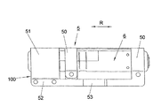
図6及び7は、本発明のガス流分配器のさらに他の実施例を示す。ガス流分配器は、筒状のガス発生器6のガス流出開口部60の領域内で、筒状のガス発生器6を取り囲む衝突要素3の形態の保持部を有している。この場合、衝突要素3は、大部分が接触しない状態で筒状のガス発生器6を囲む、ホースクリップ形状の保持部の形態である。これにより、筒状のガス発生器6のガス流出開口部60から出現するガス流を案内するためのガス案内ダクト100が、ホースクリップ形状の衝突要素3と筒状のガス発生器6の間に形成される。
6 and 7 show yet another embodiment of the gas flow distributor of the present invention. The gas flow distributor has a holding part in the form of a
筒状のガス発生器6は、固定装置7内に保持される。固定装置7は、同様にホースクリップ形状であり、前記固定装置を介して自動車構造(図示省略)に固定される。固定の目的のために、筒状のガス発生器6は、ホースクリップ形状の固定装置7内の円筒状の凹部73内に保持される。筒状のガス発生器6のガス出口開口部60の領域では、固定要素7は、ホースクリップ形状の固定要素7によって、ガス流出開口部60から流れるガスが流れ出すのが妨げられないように、カットアウト領域(切欠領域)72を有している。
The
さらに、固定要素7は、穴701、40内に案内されるリベット及び/またはスクリュー401の形態の結合要素を介して、筒状のガス発生器6を、衝突要素3と共に自動車構造に取り付けるための固定領域70を有している。固定領域70では、エアバッグは、固定領域70とクランプレール4の間に、ガス案内装置がエアバッグ織物によって囲まれるように配置される。結合要素401を締めることによって、エアバッグは、衝突要素の周りに締め付けられ、シールされ、あるいは、ガス案内装置及び/またはエアバッグを自動車構造に取り付ける手段に強固に接続される。
Furthermore, the fixing
衝突要素3は、リベット形状の固定手段401が、同様に穴301を通して案内され、それによって、ホースクリップ形状の衝突要素3がホースクリップ形状の固定要素7に固定される、同様の固定区域30を有している。
The
三日月形状のガス案内ダクト100が、ガス発生器1とホースクリップ形状の衝突要素3の間に形成されている。この場合、筒状のガス発生器6のガス流出開口部60から流れるガスは、先ず、ホースクリップ形状の衝突要素3に衝突し、そして、ガス案内ダクト100内を、2つの対向するガス流出領域101、102の方向に案内される。ここに示されている実施例では、2つのガス出口領域101、102から出現するガス流は、基本的に、互いに対向する方向、そして、筒状のガス発生器の筒軸Rに沿って出現する。この場合、ガス案内ダクト100は、ホースクリップ形状の固定要素7の外径D2及びホースクリップ形状の衝突要素3の内径D3から発生する流れ断面を有している。
A crescent-shaped
図8〜11は、本発明に対応するガス案内装置のさらなる実施例を示している。ガス案内装置は、ガス発生器6上に配置される衝突要素5の形態の保持部を有している。
Figures 8 to 11 show further embodiments of the gas guiding device according to the present invention. The gas guiding device has a holding part in the form of a
ここに示されている実施例は、図8及び9の実施例では別々に具現化されている衝突要素を、ガス発生器に対する固定要素とともに統合している。筒状のガス発生器6として設計されているガス発生器は、衝突要素5のホースクリップ形状の領域50によって囲まれている。ホースクリップ形状の領域50は、ガス流出開口部が設けられていない筒状のガス発生器6の領域に配置される。衝突要素5のさらなるホースクリップ形状の領域51は、ガス発生器6のガス流出開口部の領域に設けられ、筒状のガス発生器6を固定するホースクリップ領域50よりも大きい直径D5を有している。これは、順次、衝突要素5のホースクリップ形状の領域51と筒状のガス発生器6の間に、2つの相互に対向するガス出口領域101、102に通じるガス案内ダクト100を形成する。
The embodiment shown here integrates a collision element, which is embodied separately in the embodiment of FIGS. 8 and 9, together with a fixing element for the gas generator. The gas generator designed as a
筒状のガス発生器6及びガス流を案内するホースクリップ形状の領域51を固定する、2つのホースクリップ形状の領域50は、単一の金属シートからの単一のピースとして形成されるため、それらは、ガス案内装置を自動車構造に取り付けるための固定領域52と向かい合った位置に配置されるコモン“バック”(common “back”)を有している。したがって、ガス案内ダクト100は、筒状のガス発生器6の偏心位置から発生する三日月形状の断面を有している。
The two hose clip-shaped
ここに示されている実施例では、衝突要素5は、さらに、この領域に配置されるガスバッグ開口部を開状態に保つクランプ53を有している。これにより、ガス流は、妨げられることなくガスバッグ内に流れる。
In the embodiment shown here, the
図12〜14は、本発明に対応するガス案内装置のさらなる実施例を示している。本実施例では、ガス案内装置は、順次、ガス発生器6上に配置される衝突要素5の形態の保持部を有することが可能である。
Figures 12 to 14 show further examples of gas guiding devices according to the present invention. In this embodiment, the gas guiding device can have a holding part in the form of a
筒状のガス発生器6は、衝突要素5のホースクリップ形状の領域50によって囲まれ及び保持されている。図8〜11に示されている実施例と比べると、本実施例では、衝突要素5は、固定領域52が、ガス案内ダクト100に対向する、衝突要素5の側部に配置されるように構成されている。これにより、ガス流出開口部101、102は、同様に、固定領域と対向する、ガス案内装置の側部に配置される。個々のホースクリップ形状の領域50、51は、ガス発生器6を完全に囲む。
The
1つの実施例(図示省略)では、2つのガスバッグは、各ケース内で、少なくとも1つのガス案内ダクト100が各ガスバッグに通じるように、衝突要素3、5を結合する。この場合、衝突要素3、5は、分離ギャップの領域に、2つのガスバッグの間に配置される。これにより、衝突要素によって形成されているガス案内ダクトは、2つのガスバッグを、単一のガス発生器を使用して、一様にあるいは定められた方法で膨張させることができる。
In one embodiment (not shown), the two gas bags combine the
Claims (39)
ガス流分配器は、少なくとも流出開口部の領域で、ガス発生器を囲む、大きさが安定している保持部と、衝突要素として設計されている保持部の少なくとも1つの領域と、衝突要素とガス発生器の間に配設されている、ガス流を案内するための少なくとも1つのガス案内ダクトによって形成されており、衝突要素は、ガス流が、衝突要素に衝突することによってガス流分配器の外周面に沿う方向にそれるように配置されており、
ガス流(G)は、衝突要素(3、5)に対する衝突によって2つのガス流に分割され、これら2つのガス流は、単独のガス出口領域である、ガス案内ダクト(100)の相互に対向するガス出口領域(101、102)へとガス発生器の筒軸(R)に沿って案内される、
ことを特徴とするガス流分配器。A gas flow distributor for a side airbag module for targeted distribution of a gas flow emerging from an outlet opening of the gas generator within a gas bag inflated by the gas generator,
The gas flow distributor comprises at least one region of a holding portion that is designed to act as a collision element, surrounds the gas generator, at least in the region of the outlet opening, and a collision element. Formed by at least one gas guide duct for guiding the gas flow arranged between the gas generators, the impingement element being a gas flow distributor by the collision of the gas flow with the impingement element It is arranged to deviate in the direction along the outer peripheral surface of
The gas stream (G) is split into two gas streams by collision against the impingement elements (3, 5), which are opposite to each other in the gas guide duct (100) , which is a single gas outlet region. Guided along the cylinder axis (R) of the gas generator to the gas outlet region (101, 102)
A gas flow distributor characterized by that.
ガスバッグを膨張させるためのガス発生器と、
請求項1〜37のいずれかに記載のガス流分配器を備える、
ことを特徴とする側方エアバッグモジュール。A side airbag module,
A gas generator for inflating the gas bag;
Comprising a gas flow distributor according to any of claims 1-37,
A side airbag module characterized by that.
Applications Claiming Priority (3)
| Application Number | Priority Date | Filing Date | Title |
|---|---|---|---|
| DE20200365U DE20200365U1 (en) | 2002-01-04 | 2002-01-04 | Gas flow distributor for a side airbag module |
| DE20217892U DE20217892U1 (en) | 2002-01-04 | 2002-11-15 | Gas guiding device for side airbag module has dimensionally stable impingement element on gas generator in region of gas outlet openings so that at least one gas guiding passage for extends between impingement element and gas generator |
| PCT/DE2002/004762 WO2003059690A2 (en) | 2002-01-04 | 2002-12-23 | Gas flow distributor for a lateral airbag module |
Publications (2)
| Publication Number | Publication Date |
|---|---|
| JP2005514266A JP2005514266A (en) | 2005-05-19 |
| JP4181997B2 true JP4181997B2 (en) | 2008-11-19 |
Family
ID=26057353
Family Applications (1)
| Application Number | Title | Priority Date | Filing Date |
|---|---|---|---|
| JP2003559820A Expired - Fee Related JP4181997B2 (en) | 2002-01-04 | 2002-12-23 | Gas flow distributor for side airbag module |
Country Status (5)
| Country | Link |
|---|---|
| US (1) | US7364191B2 (en) |
| EP (1) | EP1463652B2 (en) |
| JP (1) | JP4181997B2 (en) |
| DE (1) | DE50205481D1 (en) |
| WO (1) | WO2003059690A2 (en) |
Families Citing this family (20)
| Publication number | Priority date | Publication date | Assignee | Title |
|---|---|---|---|---|
| US7108277B2 (en) * | 2001-10-12 | 2006-09-19 | Trw Vehicle Safety Systems Inc. | Air bag module with vent cover |
| GB2406312A (en) * | 2003-09-25 | 2005-03-30 | Autoliv Dev | Gas deflector |
| DE202004012303U1 (en) * | 2004-08-05 | 2004-12-09 | Trw Automotive Safety Systems Gmbh | Airbag module for a vehicle occupant restraint |
| US8168133B2 (en) * | 2005-05-09 | 2012-05-01 | Wisconsin Alumni Research Foundation | Device for performing a high throughput assay |
| US7497468B2 (en) * | 2005-05-12 | 2009-03-03 | Autoliv Asp, Inc. | Airbag inflation deflection module |
| DE202005019013U1 (en) | 2005-12-01 | 2006-04-20 | Takata-Petri (Ulm) Gmbh | Gas flow distributor for a gas bag module |
| DE102006045245A1 (en) * | 2006-09-26 | 2008-04-03 | Trw Automotive Gmbh | Retaining element and side airbag module |
| US7731234B2 (en) * | 2007-03-06 | 2010-06-08 | Trw Vehicle Safety Systems Inc. | Air bag module with diffuser |
| JP5001702B2 (en) * | 2007-03-30 | 2012-08-15 | 日本プラスト株式会社 | Airbag device |
| DE102010039902A1 (en) | 2010-08-27 | 2012-03-01 | Takata-Petri Ag | Devices for personal protection systems of a vehicle |
| CN105377639B (en) * | 2013-08-02 | 2017-06-16 | 奥托立夫开发公司 | Deflector and air bag device |
| EP3170703B1 (en) * | 2014-07-14 | 2019-03-13 | TS Tech Co., Ltd. | Side air bag device |
| DE102015006898A1 (en) * | 2015-06-03 | 2016-12-22 | Trw Airbag Systems Gmbh | An assembly of a vehicle safety system, vehicle safety system, vehicle safety device, and method for manufacturing an assembly of a vehicle safety system |
| WO2019093001A1 (en) * | 2017-11-09 | 2019-05-16 | テイ・エス テック株式会社 | Side air bag device |
| US11485311B2 (en) | 2017-11-09 | 2022-11-01 | Ts Tech Co., Ltd. | Side airbag device and method for manufacturing same |
| CN109911322B (en) * | 2019-03-26 | 2023-12-29 | 唐山智能电子有限公司 | Bag opening holding device |
| JP7115411B2 (en) * | 2019-04-23 | 2022-08-09 | 豊田合成株式会社 | Airbag device for knee protection |
| JP7124810B2 (en) * | 2019-08-26 | 2022-08-24 | 豊田合成株式会社 | side airbag device |
| US11623599B2 (en) * | 2021-04-09 | 2023-04-11 | ZF Passive Safety Systems US Inc. | Airbag with inflator attachment |
| US11299120B1 (en) * | 2021-04-15 | 2022-04-12 | Autoliv Asp, Inc. | Side airbag assemblies and methods of assembly |
Family Cites Families (20)
| Publication number | Priority date | Publication date | Assignee | Title |
|---|---|---|---|---|
| US5172933A (en) * | 1989-10-10 | 1992-12-22 | Ford Motor Company | Air bag diverter |
| US5340147A (en) * | 1991-12-19 | 1994-08-23 | Alliedsignal Inc. | Air bag inflator assembly |
| US5308108A (en) * | 1992-10-26 | 1994-05-03 | Allied-Signal Inc. | Manifold or retainer for a gas generator |
| DE9408908U1 (en) * | 1994-05-31 | 1994-11-17 | Trw Repa Gmbh | Airbag protection device |
| US5556128A (en) * | 1994-11-24 | 1996-09-17 | Volkswagen Ag | Safety arrangement for a vehicle occupant |
| US5540460A (en) | 1995-04-26 | 1996-07-30 | Trw Vehicle Safety Systems Inc. | Air bag module |
| US5704634A (en) * | 1996-02-15 | 1998-01-06 | Trw Vehicle Safety Systems Inc. | Side impact air bag module |
| US5918898A (en) | 1996-02-15 | 1999-07-06 | Trw Vehicle Safety Systems Inc. | Side impact air bag module |
| DE19626463B4 (en) | 1996-06-21 | 2005-07-07 | Takata-Petri Ag | Device for influencing the inflow of the gas into a gas bag of an airbag module |
| DE19648137C2 (en) | 1996-11-21 | 2001-10-18 | Opel Adam Ag | Airbag module |
| WO1999042340A1 (en) * | 1998-02-19 | 1999-08-26 | Breed Automotive Technology, Inc. | Exhaust regulators for airbag inflator systems |
| DE29812800U1 (en) * | 1998-07-17 | 1998-11-19 | Trw Repa Gmbh | Airbag module for a vehicle occupant restraint system |
| DE19850448B4 (en) * | 1998-11-02 | 2014-08-21 | TAKATA Aktiengesellschaft | Airbag assembly |
| DE29822159U1 (en) * | 1998-12-11 | 1999-05-12 | Trw Repa Gmbh | Airbag side impact protection device |
| US6293581B1 (en) * | 1999-04-15 | 2001-09-25 | Honda Giken Kogyo Kabushiki Kaisha | Occupant restraint device |
| FR2792592B1 (en) † | 1999-04-20 | 2001-05-18 | Livbag Snc | PROTECTION ASSEMBLY WITH AN EXTERNAL EXPANDABLE DEFLECTOR |
| AU5024500A (en) * | 1999-05-17 | 2000-12-05 | Autoliv Asp, Inc. | Side impact inflator assembly with external gas cooling |
| JP4131356B2 (en) * | 1999-07-12 | 2008-08-13 | マツダ株式会社 | Airbag device |
| DE29921743U1 (en) † | 1999-12-10 | 2000-04-13 | Trw Repa Gmbh | Vehicle occupant restraint system |
| US6595547B2 (en) * | 2001-06-01 | 2003-07-22 | Autoliv Asp, Inc. | Airbag inflator diffusion system and method of manufacture |
-
2002
- 2002-12-23 US US10/500,707 patent/US7364191B2/en not_active Expired - Lifetime
- 2002-12-23 JP JP2003559820A patent/JP4181997B2/en not_active Expired - Fee Related
- 2002-12-23 WO PCT/DE2002/004762 patent/WO2003059690A2/en active IP Right Grant
- 2002-12-23 EP EP02799038A patent/EP1463652B2/en not_active Expired - Fee Related
- 2002-12-23 DE DE50205481T patent/DE50205481D1/en not_active Expired - Lifetime
Also Published As
| Publication number | Publication date |
|---|---|
| DE50205481D1 (en) | 2006-02-02 |
| EP1463652B1 (en) | 2005-12-28 |
| US7364191B2 (en) | 2008-04-29 |
| WO2003059690A2 (en) | 2003-07-24 |
| JP2005514266A (en) | 2005-05-19 |
| EP1463652A2 (en) | 2004-10-06 |
| WO2003059690A3 (en) | 2004-04-22 |
| US20050029784A1 (en) | 2005-02-10 |
| EP1463652B2 (en) | 2009-08-19 |
Similar Documents
| Publication | Publication Date | Title |
|---|---|---|
| JP4181997B2 (en) | Gas flow distributor for side airbag module | |
| JP2664353B2 (en) | Gas bag protection device | |
| JP4050696B2 (en) | Airbag inflation gas supply apparatus and method | |
| EP1340656B1 (en) | Airbag apparatus | |
| US7185912B2 (en) | Knee protection airbag device | |
| JP3040955B2 (en) | Gas bag type side impact protection device | |
| EP1044854B1 (en) | Air bag | |
| US3625543A (en) | Safety apparatus | |
| US5605347A (en) | Airbag module with simplified cushion attachment | |
| KR19980701381A (en) | Side Impact Soft Pack Airbag Modules (SIDE IMPACT SOFT PACK AIR BAG MODULE) | |
| EP1176061B1 (en) | Airbag apparatus | |
| JPH09104318A (en) | Inflation-type locking module | |
| EP1910135A1 (en) | Airbag arranged on the vehicle roof | |
| JP2008509033A (en) | Airbag module for vehicle occupant protection | |
| JP2007230396A (en) | Airbag and airbag device | |
| US6089600A (en) | Integral gas direction device for an air bag | |
| WO2007139686A2 (en) | Inflator device having modular construction and radial inflation gas flow | |
| JP2010000825A (en) | Knee airbag device for driver's seat | |
| US20040239082A1 (en) | Overhead airbag system | |
| JP3930972B2 (en) | Airbag device | |
| CN108698552B (en) | Knee airbag module | |
| US6568708B2 (en) | Gas bag module with gas guiding means | |
| JPH0872654A (en) | Inflatable restraint device for vehicle occupant | |
| US7147248B2 (en) | Passenger air bag system for vehicles | |
| JP5912458B2 (en) | Gas supply device and airbag device |
Legal Events
| Date | Code | Title | Description |
|---|---|---|---|
| A529 | Written submission of copy of amendment under article 34 pct |
Free format text: JAPANESE INTERMEDIATE CODE: A529 Effective date: 20040830 |
|
| A621 | Written request for application examination |
Free format text: JAPANESE INTERMEDIATE CODE: A621 Effective date: 20051109 |
|
| A131 | Notification of reasons for refusal |
Free format text: JAPANESE INTERMEDIATE CODE: A131 Effective date: 20080201 |
|
| A521 | Request for written amendment filed |
Free format text: JAPANESE INTERMEDIATE CODE: A523 Effective date: 20080428 |
|
| TRDD | Decision of grant or rejection written | ||
| A01 | Written decision to grant a patent or to grant a registration (utility model) |
Free format text: JAPANESE INTERMEDIATE CODE: A01 Effective date: 20080806 |
|
| A01 | Written decision to grant a patent or to grant a registration (utility model) |
Free format text: JAPANESE INTERMEDIATE CODE: A01 |
|
| A61 | First payment of annual fees (during grant procedure) |
Free format text: JAPANESE INTERMEDIATE CODE: A61 Effective date: 20080901 |
|
| R150 | Certificate of patent or registration of utility model |
Free format text: JAPANESE INTERMEDIATE CODE: R150 |
|
| FPAY | Renewal fee payment (event date is renewal date of database) |
Free format text: PAYMENT UNTIL: 20110905 Year of fee payment: 3 |
|
| FPAY | Renewal fee payment (event date is renewal date of database) |
Free format text: PAYMENT UNTIL: 20120905 Year of fee payment: 4 |
|
| FPAY | Renewal fee payment (event date is renewal date of database) |
Free format text: PAYMENT UNTIL: 20130905 Year of fee payment: 5 |
|
| R250 | Receipt of annual fees |
Free format text: JAPANESE INTERMEDIATE CODE: R250 |
|
| R250 | Receipt of annual fees |
Free format text: JAPANESE INTERMEDIATE CODE: R250 |
|
| R250 | Receipt of annual fees |
Free format text: JAPANESE INTERMEDIATE CODE: R250 |
|
| R250 | Receipt of annual fees |
Free format text: JAPANESE INTERMEDIATE CODE: R250 |
|
| R250 | Receipt of annual fees |
Free format text: JAPANESE INTERMEDIATE CODE: R250 |
|
| LAPS | Cancellation because of no payment of annual fees |