JP4179575B2 - Face-to-face communication device and method - Google Patents
Face-to-face communication device and method Download PDFInfo
- Publication number
- JP4179575B2 JP4179575B2 JP18943099A JP18943099A JP4179575B2 JP 4179575 B2 JP4179575 B2 JP 4179575B2 JP 18943099 A JP18943099 A JP 18943099A JP 18943099 A JP18943099 A JP 18943099A JP 4179575 B2 JP4179575 B2 JP 4179575B2
- Authority
- JP
- Japan
- Prior art keywords
- face
- microphone
- sound
- room
- space
- Prior art date
- Legal status (The legal status is an assumption and is not a legal conclusion. Google has not performed a legal analysis and makes no representation as to the accuracy of the status listed.)
- Expired - Lifetime
Links
Images


Landscapes
- Interconnected Communication Systems, Intercoms, And Interphones (AREA)
Description
【0001】
【発明の属する技術分野】
本発明は、鉄道等の切符売り場、チケット等の売券売り場、又は面談システム等に見られるような部屋の内側と外側を仕切る壁を介して対面で通話をスムースに行うための対面通話装置及び方法に関する。
【0002】
【従来の技術】
従来の一般的な対面通話装置について図1の従来例を用いて説明する。
以下、対面通話装置の中から、特に売券売り場の例を挙げて説明する。
【0003】
一般的に売券売り場は、室内で切符を販売する販売者103が、切符を購入しに来る購入者104と、「切符を求める」、「切符を提供してお金を受け取る」等の会話をスムースにして、誤りの無い切符を売るようになされている。
【0004】
売券売り場には、一般に販売者103と購入者104の間に透明仕切板108が装置されていて、両者が顔を確認しながら会話できるように構成されている。透明仕切り板には音孔を装置しているが、音孔の開孔率は10−15%程度のため、販売者103と購入者104の会話で、発声の音量により良く聞こえない場合や、耳の遠くなったお年寄りとの間の十分な会話ができない場合があり、相互の通話を電気的に拡声する必要が発生する。
【0005】
お互いの会話は販売者103の音声を送話マイク106でピックアップして対面拡声装置105によって増幅し、室外スピーカ110より購入者104に伝達し、購入者104の音声は受話マイク107でピックアップして対面拡声装置105によって増幅し、室内スピーカ109より出力して販売者103に伝達し、コミュニケーションをとる。
【0006】
しかしながら、上述の対面通話装置は、購入者104が販売者103の顔を見てしゃべり、マイクの位置に注意を払わないため、マイクに適切なレベルで音声が入力しない欠点がある。
また、販売者103の拡声用のスピーカが、購入者の予測するところとは異なる位置に装置された室外スピーカ110や、受話マイク107と一体になった装置に装置されたスピーカである場合、購入者104の予測した場所と異なる場所から音声がでるため、特に初めて訪問した人は戸惑い、切符を購入するための会話がスムースに実施できない等の欠点が発生している。
【0007】
【発明が解決しようとする課題】
本発明は、かかる従来技術の現状に鑑み創案されたものであり、その目的は売券売り場等でスムースに会話ができて、容易に目的を達せられるシステムを提供することであり、特に双方向の拡声装置を使用した状態でも、購入者が販売者の顔を見て会話をするのと同じ感覚で拡声装置を用いての双方向通話ができるように、前面に音孔を持った仕切板から販売者の音声が出力され、しかも購入者が販売者の顔に近づいていったところに受話マイクが位置されるように構成した、両者のコミュニケーションや作業に間違いが発生しない対面通話装置及び方法を提供することにある。
【0008】
【課題を解決するための手段】
本発明者は、かかる目的を達成するためにコミュニケーションや作業がスムースかつ容易に行うことができる対面通話装置及び方法について鋭意検討した結果、部屋の内側と外側を仕切る壁に透明な空間を設け、さらにスピーカを装置し、その空間を介して音声を出力することによって対面通話をスムースに行えることを見出し、本発明の完成に至った。
【0009】
即ち、本発明は部屋の内側と外側を仕切る壁を介して対面で通話を行う対面通話装置において、前記壁に音孔を装置した透明板と音を遮断する透明板で構成する空間を設け、その空間にスピーカを装置するか、又はその空間に音響ダクトを装置し、その音響ダクトにスピーカを装置したことを特徴とする対面通話装置である。
【0010】
また、本発明は部屋の内側と外側を仕切る壁に音孔を装置した透明板と音を遮断する透明板で構成する空間を設け、その空間を介して対面で通話を行う対面通話方法であって、部屋の外側の者は前記空間又はその近傍のマイクロホンに音声を入力してそれを部屋の内側のスピーカに出力することによって通話し、部屋の内側の者は部屋の内側のマイクロホンに音声を入力してそれを前記空間又は前記空間に通じる場所にあるスピーカに出力し、さらに前記音孔を介して部屋の外側に出力することによって通話することを特徴とする対面通話方法である。
【0011】
部屋の内側と外側を仕切った場所での売券売り等は販売者と購入者の間のコミュニケーションがきちんとできないと、誤った切符を販売する等の間違いが生じることがあり、サービスの低下として顧客からクレームが来たり、利用客が減少したりする原因にもなる。そのために、本発明は透明な仕切板があっても、販売者と購入者の会話が増幅装置を介していても、両者が対面して自然な会話をしているような状態を作り出す、上述のような対面通話装置及び方法を提案する。
【0012】
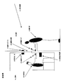
本発明の対面通話装置の例を、図2の本発明例、図2の対面ウインドウ部を拡大した図3の対面ウインドウ拡大図−1及び図4の対面ウインドウ拡大図−2を用いて説明する。
【0013】
本発明のポイントは販売者203と購入者204が対話するときに、購入者204には販売者203の声が対面ウインドウ208の音孔付仕切板303(405)から聞こえるように感じられること、そして、購入者204が対面ウインドウ208の音孔付仕切板303(405)に向かって話せば、販売者203の居る室内スピーカ210に適度な音量で明瞭に聞こえることである。
【0014】
対面ウインドウ208の室内側の透明仕切板302(402)は音響的に室内201と室外202を遮蔽する構造を有し、室外側に装置する透明板は音孔付仕切板303(405)であり、音孔314(410)を介して音響的に室外202に通じる構造を有し、透明仕切板302(402)との間で空間307(409)を作る。
【0015】
販売者203の音声は送話マイク206でピックアップされ双方向拡声装置205で増幅され、図3のように空間307に装置した室外スピーカ308で販売者203の音声が出力され、室外スピーカ308から出力された音声は音孔付仕切板303の音孔314より購入者204に向かって音声311として出力される。
【0016】
他の方法として、図4のように室外スピーカ403を対面ウインドウの近傍に設置し、室外スピーカ403より空間409に通じる音響ダクト404を装置して、販売者203の音声が音響ダクト404より空間409に出力され、音孔410から室外413の購入者204に音声412として出力されるように構成することもできる。
【0017】
次に音孔付仕切板303(405)に装置する受話マイク304(407)及び騒音検知マイク305(406)の設置方法を図3及び図4の対面ウインドウ拡大図及び図5の受話マイク設置例を用いて説明する。
【0018】
売券売り場の周辺は多くの人が歩き、外部からの自動車、空調、子供の歓声等で騒音レベルが高いことが多いので、それらの騒音に購入者204の音声がマスキングされることがある。従って、本発明では、それを防ぐため、図3及び図4のように受話マイク304(407)及び騒音検知マイク305(406)を対面ウインドウ208の周辺に設置して、何れか一方のマイクの位相を逆にし、騒音を打ち消すように構成している。このような構成により、受話マイク304(407)から入力した購入者204の音声が騒音を打ち消した状態で残ることになるので、騒音下でも明瞭な音声を室内312にいる販売者203に出力することができる。
【0019】
音孔付仕切板303(405)に装置する受話マイク304(407)は、音孔付仕切板303(405)に購入者204が最も近づき易く、かつ購入者204の音源である口が近づく位置に装置することが好ましい。例えば、受話マイク304(407)(504)は、図5の受話マイク設置例のように音孔付仕切板506の音孔505の一部に設置される。
【0020】
一方、販売者203の音声は、図3のように室外スピーカ308から空間307を通じて音孔付仕切板303の音孔314を通過する音声311として出力されるか、または図4のように室外スピーカ403から音響ダクト404及び空間409を通じて音孔付仕切板405の音孔410を通過する音声412として出力されるため、受話マイク304(407)(504)は背面の空間307(409)からの音が極力入力しないような指向性のあるマイクロホンにしてハウリングを発生しにくい構成とすることが好ましい。
【0021】
以上のシステムを動作させるためには、例えば図6の双方向拡声系統図に従った構成を採用する。即ち、送話マイク601を増幅602に接続し適切なレベルにして、ハウリング等を抑圧するATT603を経て増幅604に接続し、適切な出力レベルとするATT605を経て増幅606に接続し、出力増幅607の出力を室外スピーカ609と窓口の送話スピーカ610に切りかえる切替スイッチ608に接続し、切替スイッチにより選択できるようにする。
【0022】
また、購入者の音声を受ける受話マイク611と騒音制御マイク623を例えば対面ウインドウ624に装置し、騒音制御マイク623の位相を位相制御612によって制御し、騒音制御マイク623と受話マイク611の騒音を制御する騒音制御613に入力し、出力を増幅614に接続し、音声検知622からの信号で適切なレベルとするATT615を経て増幅装置617に入力する。
【0023】
さらに、音声検知616により受話マイク611からのレベルを検知し、さらに増幅617と増幅602の出力をそれぞれATT618とATT603で制御し、ATT618からの信号は増幅619と出力620で適切なレベルに増幅され、室内スピーカ621を駆動する。
【0024】
【発明の実施の形態】
以下、本発明の対面通話装置と方法の好ましい態様を切符販売を例にして具体的に説明するが、本発明はこれに限定されるものではない。
【0025】
本発明の装置は、図2のように室内201の販売者203が室外202の購入者204と対面する対面ウインドウ208を透明仕切板302と音孔付仕切板303で構成し、両仕切板の間に空間ができるように構成している。購入者204が切符売り場に近づくと、対面ウインドウ208から確認できるうえに、人間の体温、音響、レーダー方式、圧力スイッチ等で購入者が切符売り場に来たことを近接センサー214(627)によって検知することができる。この検知信号を増幅628で増幅し、音量減衰装置のATT629を開放状態として増幅614の出力を通過させる。近接センサー214(627)が動作することで、購入者204がカウンター215の前に来ると、双方向拡声装置205は双方の会話を拡声装置を用いてできるように準備する。
【0026】
室内201にいる販売者203が例えば目的駅を確認する質問を発声すると、送話マイク206(601)に音声が入力される。送話マイク601に入力した販売者203の音声は増幅602で適切なレベル、−20dB程度のレベルまで増幅して、次段の増幅604に入力されるが、増幅602と増幅604の間にATT603を装置している。
【0027】
ATT603は、購入者204の声が小さく聞こえない場合に販売者203が音量を上げたとき、あるいは増幅装置614内にある自動音量調整が動作したとき、受話マイク611の感度が上がり、送話スピーカ610の音も拾うことにより起こるハウリングや、受話マイクの音量が上昇したときに起こるハウリングの発生を防ぐために送話マイク601の音量を制御する目的で装置している。
【0028】
増幅604の出力はATT605を介して増幅606に入力する。増幅604と増幅606の中間にあるATT605は、対面ウインドウ内の出力が適切かどうかをリアルタイムに調整する装置として具備されている。送話マイク601のレベルは出力増幅607より送話スピーカ610によって対面ウインドウ624に出力し、さらに購入者に伝送されるが、対面ウインドウ内には受話マイク611があり、受話マイク611が送話マイク601の音を拾い、室内スピーカ621から出力され、前記出力が送話マイク601に入力する音響ループでハウリングを発生させない限度の出力の許容値を、音声検知616によってリアルタイムに検知し、対面ウインドウ内でのハウリングレベルに余裕があれば、音声検知616によりATT603が減衰量を調整する等、受話マイク611によってウインドウ内の音量レベルを音声検知622でリアルタイムにレベル確認をし、対面ウインドウ624からの出力を適切とするように動作する。
【0029】
増幅606は、送話スピーカ610、室外スピーカ609を駆動させるために必要な電力増幅を行う出力増幅607に出力するように構成され、出力増幅607は、送話スピーカ610と室外スピーカ609のいずれかを動作させるための切替スイッチ608で何れかに出力するように構成されている。室外スピーカ609は、駅としての一般的な案内を室外にいる複数の購入者に行うときや、切符の購入者が勘違いして窓口を離れたときなどに使用する。
【0030】
図3の対面ウインドウ拡大図では、室外スピーカ308は対面ウインドウの上面に設置され、対面ウインドウ内に向けて出力するようになっている。実際には、室外スピーカ308よりの音声は透明仕切板302と音孔付仕切板303との間の空間307に出力され、出力された音声は音孔付仕切板303の複数の音孔314より、対面ウインドウ208の真正面に居る購入者204に出力される。このような室外スピーカ308の配置により発生する音孔314からの音は購入者204にとって、あたかも正面に見える販売者203から直接聞こえるように錯覚する。その結果、販売員203の音声が対面ウインドウ208から聞こえてくると、購入者204は対面ウインドウ208に顔を近づけてくる。
【0031】
購入者204の音声は対面ウインドウ208の正面に装置されている受話マイク207に入力され、増幅614によって−20dB程度のレベルに増幅され、増幅617に渡される。増幅614と増幅617の間にはATT629とATT615が装置され、ATT629は購入者が対面通話装置に近接するまでは受話マイク611の信号が増幅装置617に入力しないように大きな減衰を与え、室内スピーカを無音状態とし、近接センサー627が購入者204の接近を検知するとATT629の減衰を設定されたレベルまで解除して、適切なレベルで増幅614の信号を通過させる。
【0032】
音声検知616は受話マイク611のレベルを検知してATT618で受話マイク611のレベルを調整し、また、受話マイク611のレベルに応じた最適な送話スピーカ610の出力となるようにATT603は音声検知616によって動作する。ATT618は増幅619と出力620を介して適切な室内スピーカ621の出力レベルとなるようにする。
【0033】
以上の対面通話装置を図7のシステムフローを用いて説明する。
購入者が窓口に接近すると(702)、近接センサーが検知し、対面ウインドウに設置した受話マイクの音が室内に出力して(703)、購入者が来たことを室内の販売員は知ることができる。あるいは、近接センサーに購入者が近接したときに購入者が来たことを知らせる表示装置によっても室内の切符販売員は知ることができる。
購入者の接近を音声あるいは表示で認知した販売者は音声を発すると送話マイクから応答して、対面ウインドウ内の空間に販売者の音声が出力し(704)、仕切板の音孔から購入者に出力し、あたかも販売員から聞こえたように感じ(705)、購入者は用件を対面ウインドウに向かって伝えると、室内のスピーカから購入者の音声が聞こえる(706)。
【0034】
本発明の装置の対面ウインドウの構造を図3及び図4の拡大図で説明すると、対面ウインドウはお互いの顔が見える大きさと透明性を有するものとして、室内312(411)側と室外313(413)側にそれぞれ仕切板が設けられる。対面ウインドウの室内312(411)側の仕切板は透明で音孔等が一切無い構造を有し、例えばガラス、アクリル板等の透明な板状のものを使用して遮音性の構造として装置される。一方、室外313(413)側の仕切板は透明で複数の音孔314(410)を設けた構造を有し、例えばガラス、アクリル板等の透明な板状のものを使用して音が通過する構造として装置される。
【0035】
具体的には、図3のように室内(312)側の透明仕切板302と室外(313)側の音孔付仕切板303の構成する空間307にスピーカ308を装置し、スピーカ308より音声を出力して、音孔付仕切板303に装置した音孔314より音声311を室外313側に出力するか、又は、図4のようにスピーカ403を空間409に通じる壁の一部あるいは対面ウインドウの近くに装置し、前記スピーカ403より音声を出力して、音響ダクト404を通って透明仕切板402と音孔付仕切板405で構成する空間409に音声を出力し、次いで音孔410から室外413側に音声を出力するように構成する。
【0036】
以上の二つの方式は空間307に直接に音声を出力するか、又は空間409に通じる音響ダクトを介して音声を出力するかの違いであり、壁の構造や壁の厚さ等によって適宜選択することが好ましい。いずれの方式によっても販売員203の音声があたかも透明板を通過して明瞭に聞こえて来るように錯覚するため、購入者は対面ウインドウに顔を近づけてくる傾向があり、結果としてコミュニケーションや作業の迅速さにつながる効果を有し、本発明の最も特徴とする発明のポイントである。
【0037】
次に本発明の装置における購入者のマイクロホンに入力する外部雑音を抑制する装置を説明する。駅等の切符を販売するような場所では、極めて多くの人が歩いており、子供の大きな声、物をぶつける音、引き摺ったような音等、様々な雑音がある。このような雑音状態の中で、購入者204の音声が小さいときには音声検知616によって音量レベルを上げることができるが、音量を上げても外部の騒音も同時に上がるので明瞭度が良くならない場合がある。
【0038】
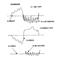
本発明ではかかる場合に対処するため、対面ウインドウに受話マイク207と騒音検知マイク213を装置して騒音を低減させる構成を取っている。この場合、受話マイク207(611)と騒音検知マイク213は互いに近い位置に装置するが、購入者204の音声は受話マイク207(611)に入力するように構成し、騒音制御マイク623は購入者204の音声が入りにくい位置に装置することが好ましい。そのように配置すると、音声の無いときは、室外202の雑音が前記の両マイクに雑音として入力する。即ち、図8の雑音制御説明図を用いて説明すると、受話マイク611には騒音波形802が、騒音検知マイク623には雑音波形804が入力し、前記波形は騒音制御マイク623と受話マイク611では同じ波形である。それは両方のマイクが雑音源からの距離を考えればほぼ同じ位置にあると考えて良い。
【0039】
いずれのマイクの入力でも良いが、図6では雑音制御マイク623の系に位相制御612を装置し、位相を逆にして混合すると、同じレベルで位相を変えていない受話マイク611に入力した雑音波形と、騒音制御マイク623に入力した騒音波形が打ち消しあって、雑音制御613からは受話マイク611に入力していた購入者の音声波形が出力される。以上のように構成することにより、室外の雑音を打ち消し、購入者204の音声だけを明瞭に室内201に居る販売者203に伝えることができるため、間違いのないスムースな販売が可能である。
【0040】
次に本発明の装置に設置される近接センサーについて説明する。
駅等の切符を販売する販売場所は、昼間は連続して購入者204が来るから、販売者203も連続した仕事として対応するが、早朝、夜間等の購入者204が少ないときは、販売者203を常に置いておくことは無駄なため、他の仕事との兼務になるが、購入者が来た時はすぐにも対応可能なように、購入者が来たときに、人間の体温、音響、レーダー方式、圧力スイッチ等の機能のセンサーを近接センサーとして室外に装置する。近接センサー出力を増幅628によってON-OFF信号等の信号変化と表示装置が点燈するようにするか、あるいは信号音が発生するように構成する。これによって販売者203は対面ウインドウの前に常時いなくても購入者が来たことを容易に知ることができる。
【0041】
しかしながら、近接スイッチのみにより、購入者が来たことを販売者203に知らせる方法だと、小さな子供が近づいたり荷物を置いただけで誤動作により、別の仕事をしていた販売者が対面ウインドウに来なければならない可能性がある。従って、システムの信頼性の向上のためには、近接センサー627による購入者204の近接情報に加えて、受話マイクへの購入者204の音声情報を利用することが好ましい。例えば購入者204が販売者203を呼ぶような声を発すると、騒音制御613の音声レベルを1−0信号にして増幅628に入力し、近接センサー信号の1−0信号とでAND動作をさせ、両方の入力が入力状態となった時に、ATT629の減衰をゼロにするか、あるいは購入者が来たことを知らせる表示630を点燈する等の動作を行なわせるように構成する。
【0042】
本発明の装置では、上述のように室外スピーカ308(403)の音声が空間307(409)に出力し、音孔付仕切板303(405)に装置している多数の音孔314(410)から音声を室外に出すように装置した構成を有するが、受話マイク304(407)を音孔付仕切板303(405)の音孔314(410)の一部に装置する場合には、受話マイク304(407)は、購入者204が音孔314(410)からの音声を聞きながら話す位置を考慮して音孔付仕切板501の中央付近に装置することが最も適切である。
【0043】
受話マイクは図5のように音孔の形状に適合したデザインで仕切板に取付けることによって、購入者の口元はマイクを意識せずに仕切板に近づく傾向がある。ここで特徴的なことは、背面の空間に出力する音声が小さければ小さいほど、購入者204は音孔付仕切板501にさらに近づき、受話マイク504に接近するので、内部に居る販売者203は購入者の音声をより明瞭に聞き取ることができることである。
【0044】
さらに、音孔付仕切板501に装置する受話マイク504を購入者側に向いた指向性マイクとすることによって、背面の空間に出力されている音声が受話マイク504に入力するのを抑えられ、ハウリングマージンを稼ぐことができる。但し、受話マイク611に指向性マイクを使用することでハウリングマージンをとることはできても、音響工学的には音声出力のスピーカの前にマイクを装置しているのと同じ構造であるため、増幅614のラインの状況をリアルタイムに音声検知616がウオッチし室内スピーカ621の出力が送話マイク601に過大に入ってハウリングをしない様にATT618でマイクの音量に従ってコントロールし、室内スピーカの出力が一定になるように構成することが好適である。
【0045】
【発明の効果】
本発明の対面通話装置及び方法は上述のような構成を有するので以下のような効果を奏することができる:
(i)駅の切符販売、映画館の切符販売のような室内と室外を仕切った双方向の対面通話システムにおいて、誤解を発生させずに迅速にコミュニケーションや作業を行うことができる。特に購入者は販売者の音声を対面ウインドウから聞くため、購入者は対面ウインドウに顔を近づけてコミュニケーションをする傾向があり、スムースで自然な対話が可能である。
(ii)購入者のマイクロホンに入力する外部雑音を抑圧する装置によって販売者は購入者の音声だけを明瞭に聞くことができる。
(iii) 購入者が来たことを知らせる近接センサーによって、販売者は必要時のみ対面ウインドウに来て応対すれば良く作業効率が格段に向上する。さらに近接センサーに加えて、受話マイクへの購入者の音声情報を利用することによって、購入者の来訪の感知精度がさらに向上する。
(iv)透明な対面ウインドウで室内・室外を仕切っているので、室内の者が室外から直接危害を加えられることはない。
【図面の簡単な説明】
【図1】駅の切符販売における従来例の説明図。
【図2】駅の切符販売における本発明の説明図。
【図3】対面ウインドウの構造例を説明する対面ウインドウの断面図。
【図4】対面ウインドウの構造例を説明する対面ウインドウの断面図。
【図5】音孔付仕切板に装置した受話マイクの設置例。
【図6】本発明の装置の双方向拡声系統図。
【図7】本発明の動作方法についてのシステムフロー。
【図8】本発明の装置の雑音制御説明図。
【符号の説明】
101 室内
102 室外
103 販売者
104 購入者
105 対面拡声装置
106 送話マイク
107 受話マイク
108 透明仕切板
109 室内スピーカ
110 室外スピーカ
111 室外騒音
201 室内
202 室外
203 販売者
204 購入者
205 双方向拡声装置
206 送話マイク
207 受話マイク
208 対面ウインドウ
209 壁
210 室内スピーカ
211 室外スピーカ
212 引渡孔
213 騒音検知マイク
214 近接センサー
215 カウンター
301 壁
302 透明仕切板
303 音孔付仕切板
304 受話マイク
305 騒音検知マイク
306 引渡孔
307 空間
308 室外スピーカ
310 室内スピーカ
311 音声
312 室内
313 室外
314 音孔
401 壁
402 透明仕切板
403 室外スピーカ
404 音響ダクト
405 音孔付仕切板
406 騒音検知マイク
407 受話マイク
408 引渡孔
409 空間
410 音孔
411 室内
412 音声
413 室外
501 音孔付仕切板
502 受話マイク
503 拡大図
504 受話マイク
505 音孔
506 音孔付仕切板
601 送話マイク
602 増幅
603 ATT
604 増幅
605 ATT
606 増幅
607 出力増幅
608 切替スイッチ
609 室外スピーカ
610 送話スピーカ
611 受話マイク
612 位相制御
613 騒音制御
614 増幅
615 ATT
616 音声検知
617 増幅
618 ATT
619 増幅
620 出力
621 室内スピーカ
622 音声検知
623 騒音制御マイク
624 対面ウインドウ
625 室外
626 室内
627 近接センサー
628 増幅
629 ATT
630 表示
701−706 システムフロー
801 受話マイク信号
802 騒音波形
803 購入者音声波形
804 雑音波形
805 騒音検知マイク信号
806 購入者音声波形
807 合成波形[0001]
BACKGROUND OF THE INVENTION
The present invention relates to a face-to-face call device for smoothly performing a face-to-face call through a wall that partitions the inside and outside of a room as seen in a ticket office such as a railway, a ticket office such as a ticket, or an interview system, and the like Regarding the method.
[0002]
[Prior art]
A conventional general face-to-face communication device will be described using the conventional example of FIG.
Hereinafter, an example of a ticket office will be described from among the face-to-face communication devices.
[0003]
In general, in a ticket office, a seller 103 who sells a ticket in a room has a conversation with a buyer 104 who comes to purchase a ticket, such as “request a ticket” or “provide a ticket and receive money”. It is designed to sell tickets that are smooth and error free.
[0004]
In the ticket vending section, a transparent partition plate 108 is generally installed between the seller 103 and the purchaser 104 so that both can talk while checking their faces. Sound holes are provided in the transparent partition plate, but the sound hole opening rate is about 10-15%, so in the conversation between the seller 103 and the purchaser 104, when the sound volume is not heard well, In some cases, it may not be possible to sufficiently communicate with an elderly person who is far away from the ear, and it is necessary to electrically amplify each other's call.
[0005]
In the conversation with each other, the voice of the seller 103 is picked up by the transmission microphone 106 and amplified by the face-to-face loudspeaker 105 and transmitted to the purchaser 104 through the outdoor speaker 110, and the voice of the purchaser 104 is picked up by the reception microphone 107. Amplified by the face-to-face loudspeaker 105, output from the indoor speaker 109 and transmitted to the seller 103 for communication.
[0006]
However, the above-described face-to-face communication device has a drawback that the purchaser 104 does not pay attention to the position of the microphone because the buyer 104 looks at the face of the seller 103 and does not pay attention to the position of the microphone.
Further, when the loudspeaker speaker of the seller 103 is an outdoor speaker 110 installed at a position different from that predicted by the purchaser or a speaker integrated with the receiver microphone 107, the purchase is performed. Since the voice comes from a place different from the place predicted by the person 104, the person who visits for the first time is particularly confused, and the conversation for purchasing the ticket cannot be carried out smoothly.
[0007]
[Problems to be solved by the invention]
The present invention was devised in view of the current state of the prior art, and its purpose is to provide a system that enables smooth conversation at a ticket office and the like, and can be easily achieved. A partition plate with a sound hole on the front so that a buyer can make a two-way call using the loudspeaker as if the buyer had a conversation looking at the seller's face even when using the loudspeaker And a method for in-person communication where the receiver's voice is output and the receiver microphone is positioned where the purchaser is approaching the seller's face, so that there is no error in both communication and work Is to provide.
[0008]
[Means for Solving the Problems]
As a result of earnestly studying a face-to-face communication device and method capable of performing communication and work smoothly and easily in order to achieve such an object, the present inventor has provided a transparent space on the wall separating the inside and the outside of the room, Furthermore, the present inventors have found that a face-to-face call can be smoothly performed by installing a speaker and outputting sound through the space, thereby completing the present invention.
[0009]
That is, the present invention provides a face-to-face communication device that performs face-to-face communication through a wall that partitions the inside and outside of a room, and provides a space configured by a transparent plate that has a sound hole on the wall and a transparent plate that blocks sound, A face-to-face communication device characterized in that a speaker is installed in the space, or an acoustic duct is installed in the space, and a speaker is installed in the acoustic duct.
[0010]
In addition, the present invention provides a face-to-face call method in which a space configured by a transparent plate provided with a sound hole and a transparent plate that blocks sound is provided in a wall that partitions the inside and outside of a room, and a face-to-face call is made through the space. The person outside the room talks by inputting sound into the microphone in or near the space and outputting it to the speaker inside the room, and the person inside the room sends the sound to the microphone inside the room. It is a face-to-face call method characterized in that a call is made by inputting and outputting it to a speaker in the space or a place communicating with the space, and further to the outside of the room through the sound hole.
[0011]
When selling tickets at a place where the inside and outside of the room are partitioned, if the communication between the seller and the purchaser is not properly made, mistakes such as selling wrong tickets may occur, and the service is degraded. Will cause complaints and a decrease in customers. For this reason, the present invention creates a state in which the conversation between the seller and the purchaser is conducted through the amplifying device, even if there is a transparent partition plate, and both parties face each other and have a natural conversation. A face-to-face communication apparatus and method are proposed.
[0012]
An example of the face-to-face communication apparatus of the present invention will be described with reference to the example of the present invention of FIG. 2, the face-to-face enlarged view of FIG. 3 in which the face-to-face window portion of FIG. 2 is enlarged, and the face-to-face enlarged view of FIG. .
[0013]
The point of the present invention is that when the seller 203 and the purchaser 204 interact, the purchaser 204 feels that the voice of the seller 203 can be heard from the sound hole partition plate 303 (405) of the facing window 208. When the purchaser 204 speaks toward the sound hole partition plate 303 (405) of the facing window 208, the purchaser 204 can clearly hear the room speaker 210 where the seller 203 is present at an appropriate volume.
[0014]
The transparent partition plate 302 (402) on the indoor side of the facing window 208 has a structure that acoustically shields the indoor 201 and the outdoor 202, and the transparent plate installed on the outdoor side is a partition plate 303 (405) with a sound hole. The space 307 (409) is formed between the transparent partition plate 302 (402) and acoustically communicating with the outdoor 202 through the sound hole 314 (410).
[0015]
The voice of the seller 203 is picked up by the transmission microphone 206 and amplified by the bidirectional loudspeaker 205, and the voice of the seller 203 is output by the outdoor speaker 308 installed in the space 307 as shown in FIG. The sound is output as sound 311 from the sound hole 314 of the partition plate 303 with sound hole toward the purchaser 204.
[0016]
As another method, as shown in FIG. 4, an outdoor speaker 403 is installed in the vicinity of the facing window, and an acoustic duct 404 communicating with the space 409 from the outdoor speaker 403 is installed. It can also be configured to be output as sound 412 from the sound hole 410 to the purchaser 204 outside the room 413.
[0017]
Next, the installation method of the reception microphone 304 (407) and the noise detection microphone 305 (406) to be installed on the partition plate 303 (405) with a sound hole will be described in enlarged views of the facing windows of FIGS. 3 and 4 and the installation example of the reception microphone of FIG. Will be described.
[0018]
Many people walk around the ticket office and the noise level is often high due to automobiles, air conditioning, cheering children, etc. from outside, so the voice of the purchaser 204 may be masked by those noises. Therefore, in the present invention, in order to prevent this, the receiving microphone 304 (407) and the noise detection microphone 305 (406) are installed around the facing window 208 as shown in FIGS. It is configured to reverse the phase and cancel the noise. With such a configuration, since the voice of the purchaser 204 input from the receiving microphone 304 (407) remains in a state in which noise is canceled, clear voice is output to the seller 203 in the room 312 even under noise. be able to.
[0019]
The receiving microphone 304 (407) installed in the sound hole partition plate 303 (405) is the position where the purchaser 204 is most likely to approach the sound hole partition plate 303 (405) and the position where the mouth which is the sound source of the purchaser 204 approaches. It is preferable to install in For example, the receiving microphones 304 (407) and 504 are installed in a part of the
[0020]
On the other hand, the voice of the seller 203 is output as the voice 311 passing through the sound hole 314 of the partition plate 303 with sound holes from the outdoor speaker 308 through the space 307 as shown in FIG. 3, or as the outdoor speaker as shown in FIG. 403 is output as sound 412 that passes through the sound hole 410 of the sound hole partitioning plate 405 through the acoustic duct 404 and the space 409, so that the receiving microphones 304 (407) and 504 receive sound from the back space 307 (409). It is preferable that the microphone has a directivity so as not to input as much as possible so that howling is less likely to occur.
[0021]
In order to operate the above system, for example, a configuration according to the bidirectional loudspeaker diagram of FIG. 6 is adopted. That is, the transmission microphone 601 is connected to the
[0022]
In addition, a reception microphone 611 and a
[0023]
Further, the level from the receiving microphone 611 is detected by the
[0024]
DETAILED DESCRIPTION OF THE INVENTION
Hereinafter, preferred embodiments of the face-to-face communication apparatus and method of the present invention will be specifically described by taking ticket sales as an example, but the present invention is not limited to this.
[0025]
In the apparatus of the present invention, as shown in FIG. 2, a facing window 208 where a seller 203 in a room 201 faces a purchaser 204 in an outdoor room 202 is composed of a transparent partition plate 302 and a partition plate 303 with a sound hole. It is configured to create a space. When the purchaser 204 approaches the ticket counter, it can be confirmed from the face-to-face window 208, and the proximity sensor 214 (627) detects that the purchaser has come to the ticket counter with human body temperature, sound, radar system, pressure switch, or the like. can do. This detection signal is amplified by the amplifier 628, and the output of the amplifier 614 is allowed to pass with the ATT 629 of the volume attenuation device opened. When the proximity sensor 214 (627) operates, when the purchaser 204 comes in front of the counter 215, the two-way loudspeaker 205 prepares for both conversations using the loudspeaker.
[0026]
For example, when the seller 203 in the room 201 utters a question confirming the destination station, a voice is input to the transmission microphone 206 (601). The voice of the seller 203 input to the transmission microphone 601 is amplified to an appropriate level of about -20 dB by the
[0027]
The ATT 603 increases the sensitivity of the receiving microphone 611 when the seller 203 increases the volume when the voice of the purchaser 204 cannot be heard or when the automatic volume adjustment in the amplifying device 614 operates, and the transmitting speaker increases. In order to prevent howling caused by picking up the sound of 610 and howling that occurs when the volume of the receiving microphone increases, the apparatus is controlled for the purpose of controlling the volume of the transmitting microphone 601.
[0028]
The output of the
[0029]
The
[0030]
In the enlarged view of the facing window in FIG. 3, the outdoor speaker 308 is installed on the upper surface of the facing window and is output toward the facing window. Actually, the sound from the outdoor speaker 308 is output to the space 307 between the transparent partition plate 302 and the sound hole partition plate 303, and the output sound is output from the plurality of sound holes 314 of the sound hole partition plate 303. , And output to the purchaser 204 in front of the facing window 208. The sound from the sound hole 314 generated by such an arrangement of the outdoor speaker 308 makes an illusion that the purchaser 204 can directly hear the sound from the seller 203 that is visible in the front. As a result, when the voice of the salesperson 203 is heard from the facing window 208, the purchaser 204 brings his face closer to the facing window 208.
[0031]
The voice of the purchaser 204 is input to the receiving microphone 207 installed in front of the facing window 208, amplified to a level of about −20 dB by the amplification 614, and passed to the
[0032]
The
[0033]
The above face-to-face communication device will be described with reference to the system flow of FIG.
When the purchaser approaches the window (702), the proximity sensor detects and the sound of the receiving microphone installed in the facing window is output to the room (703), and the salesperson in the room knows that the purchaser has come. Can do. Alternatively, the ticket salesperson in the room can also know by a display device that notifies the purchaser when the purchaser approaches the proximity sensor.
The seller who recognizes the approach of the purchaser by voice or display responds from the transmitting microphone when the voice is emitted, and the seller's voice is output to the space in the facing window (704) and purchased from the sound hole of the partition plate. The purchaser feels as if it was heard from the salesperson (705), and when the purchaser conveys the message to the facing window, the voice of the purchaser is heard from the speaker in the room (706).
[0034]
The structure of the facing window of the apparatus of the present invention will be described with reference to the enlarged views of FIGS. 3 and 4. The facing window has a size and transparency so that each face can be seen, and the indoor 312 (411) side and the outdoor 313 (413). ) Sides are each provided with a partition plate. The partition plate on the indoor window 312 (411) side of the facing window has a structure that is transparent and has no sound holes or the like. For example, a transparent plate-like material such as glass or an acrylic plate is used as a sound insulating structure. The On the other hand, the partition plate on the outdoor 313 (413) side is transparent and has a structure provided with a plurality of sound holes 314 (410). For example, a transparent plate-like material such as glass or an acrylic plate is used to pass sound. As a structure to do.
[0035]
Specifically, as shown in FIG. 3, a speaker 308 is installed in a space 307 formed by the transparent partition plate 302 on the indoor (312) side and the partition plate 303 with sound holes on the outdoor (313) side. The sound 311 is output to the outdoor 313 side from the sound hole 314 installed in the partition plate 303 with sound holes, or the speaker 403 is part of the wall leading to the space 409 or the facing window as shown in FIG. The sound is output from the speaker 403, the sound is output through the acoustic duct 404 to the space 409 configured by the transparent partition plate 402 and the sound hole-equipped partition plate 405, and then from the sound hole 410 to the outdoor 413. The voice is output to the side.
[0036]
The above two methods are different depending on whether the sound is directly output to the space 307 or the sound is output via an acoustic duct leading to the space 409, and is appropriately selected depending on the wall structure, the wall thickness, and the like. It is preferable. With either method, the purchaser's voice tends to come closer to the face-to-face window because the salesperson 203's voice is clearly heard through the transparent plate, resulting in communication and work. This has the effect of leading to speed, and is the most characteristic feature of the present invention.
[0037]
Next, an apparatus for suppressing external noise input to the purchaser's microphone in the apparatus of the present invention will be described. In places where tickets are sold, such as stations, a large number of people are walking, and there are various noises such as loud voices of children, sounds of hitting objects, and sounds of dragging. In such a noise state, when the voice of the purchaser 204 is low, the sound level can be increased by the
[0038]
In the present invention, in order to deal with such a case, the receiving microphone 207 and the noise detection microphone 213 are installed in the facing window to reduce the noise. In this case, the reception microphone 207 (611) and the noise detection microphone 213 are installed at positions close to each other, but the voice of the purchaser 204 is configured to be input to the reception microphone 207 (611), and the
[0039]
In FIG. 6, when the phase control 612 is provided in the system of the
[0040]
Next, the proximity sensor installed in the apparatus of the present invention will be described.
Since the purchaser 204 comes continuously in the daytime to sell the ticket at a station or the like, the seller 203 also responds as a continuous job. Since it is useless to keep 203 at all times, it becomes a concurrent job with other work, but when the buyer comes, when the purchaser comes, Sensors with functions such as sound, radar system, and pressure switch are installed outside as outdoor proximity sensors. The proximity sensor output is configured so that a signal change such as an ON-OFF signal or the like is lit by an amplifier 628 or a signal sound is generated. As a result, the seller 203 can easily know that the purchaser has come without having to always be in front of the facing window.
[0041]
However, with the method of notifying the seller 203 that the purchaser has come by using only the proximity switch, the seller who has done another job comes to the face-to-face window due to a malfunction caused by a small child approaching or placing a baggage. It may be necessary. Therefore, in order to improve the reliability of the system, it is preferable to use the voice information of the purchaser 204 to the receiving microphone in addition to the proximity information of the purchaser 204 by the
[0042]
In the apparatus of the present invention, as described above, the sound of the outdoor speaker 308 (403) is output to the space 307 (409) and the sound holes 314 (410) installed in the sound hole partition plate 303 (405). However, when the receiving microphone 304 (407) is installed in a part of the sound hole 314 (410) of the partition plate 303 (405) with a sound hole, the receiving microphone is used. It is most appropriate that 304 (407) is installed near the center of the
[0043]
The receiving microphone is attached to the partition plate with a design adapted to the shape of the sound hole as shown in FIG. 5, so that the purchaser's mouth tends to approach the partition plate without being aware of the microphone. What is characteristic here is that the smaller the sound output to the back space, the closer the purchaser 204 gets closer to the sound
[0044]
Furthermore, by making the receiving microphone 504 installed on the partition plate with sound holes 501 a directional microphone facing the purchaser side, it is possible to suppress the sound output to the back space from being input to the receiving microphone 504, Earn a howling margin. However, although a howling margin can be obtained by using a directional microphone for the receiving microphone 611, the acoustic engineering has the same structure as that in which a microphone is installed in front of a speaker for audio output. The state of the amplification 614 line is controlled in accordance with the volume of the microphone with ATT 618 so that the
[0045]
【The invention's effect】
Since the face-to-face communication apparatus and method of the present invention have the above-described configuration, the following effects can be obtained.
(I) In a two-way face-to-face communication system in which a room is separated from the outside, such as station ticket sales and cinema ticket sales, communication and work can be performed quickly without causing misunderstandings. In particular, since the purchaser listens to the voice of the seller from the face-to-face window, the purchaser tends to communicate with the face close to the face-to-face window, and a smooth and natural dialogue is possible.
(Ii) The seller can clearly hear only the voice of the purchaser by the device that suppresses external noise input to the purchaser's microphone.
(iii) With the proximity sensor that informs the purchaser that the purchaser has come, it is sufficient for the seller to come to the face-to-face window and respond to it only when necessary. Further, by using the purchaser's voice information to the receiving microphone in addition to the proximity sensor, the purchaser's visit sensing accuracy is further improved.
(Iv) Since indoors and outdoors are separated by a transparent facing window, indoor persons are not directly harmed from outside.
[Brief description of the drawings]
FIG. 1 is an explanatory diagram of a conventional example of ticket sales at a station.
FIG. 2 is an explanatory diagram of the present invention in ticket sales at a station.
FIG. 3 is a cross-sectional view of a facing window for explaining an example of the structure of the facing window.
FIG. 4 is a cross-sectional view of a facing window for explaining an example of the structure of the facing window.
FIG. 5 shows an installation example of a receiving microphone installed on a partition plate with a sound hole.
FIG. 6 is a bidirectional loudspeaker system diagram of the apparatus of the present invention.
FIG. 7 is a system flow of the operation method of the present invention.
FIG. 8 is an explanatory diagram of noise control of the apparatus of the present invention.
[Explanation of symbols]
101 room
102 outdoor
103 seller
104 Buyer
105 Face-to-face loudspeaker
106 Mic
107 microphone
108 Transparent partition plate
109 Indoor speaker
110 Outdoor speaker
111 outdoor noise
201 room
202 Outdoor
203 Seller
204 Purchaser
205 Two-way loudspeaker
206 Speaking microphone
207 microphone
208 face-to-face window
209 wall
210 Indoor speakers
211 Outdoor speaker
212 Delivery hole
213 Noise detection microphone
214 Proximity sensor
215 counter
301 wall
302 Transparent partition plate
303 Partition with sound hole
304 microphone
305 Noise detection microphone
306 Delivery hole
307 space
308 Outdoor speaker
310 Indoor Speaker
311 voice
312 room
313 outdoor
314 sound hole
401 wall
402 Transparent partition plate
403 outdoor speaker
404 acoustic duct
405 Partition plate with sound hole
406 Noise detection microphone
407 microphone
408 Delivery hole
409 space
410 sound hole
411 room
412 voice
413 outdoor
501 Partition with sound hole
502 microphone
503 Enlarged view
504 Telephone microphone
505 sound hole
506 Partition plate with sound hole
601 Sending microphone
602 amplification
603 ATT
604 amplification
605 ATT
606 amplification
607 Output amplification
608 selector switch
609 Outdoor speaker
610 Speaker
611 microphone
612 Phase control
613 Noise control
614 amplification
615 ATT
616 Voice detection
617 amplification
618 ATT
619 Amplification
620 output
621 Indoor speaker
622 Voice detection
623 Noise control microphone
624 face-to-face window
625 outdoor
626 room
627 Proximity sensor
628 amplification
629 ATT
630 displays
701-706 system flow
801 Receive microphone signal
802 Noise waveform
803 Purchaser voice waveform
804 Noise waveform
805 Noise detection microphone signal
806 Purchaser voice waveform
807 Composite waveform
Claims (10)
Priority Applications (1)
| Application Number | Priority Date | Filing Date | Title |
|---|---|---|---|
| JP18943099A JP4179575B2 (en) | 1999-07-02 | 1999-07-02 | Face-to-face communication device and method |
Applications Claiming Priority (1)
| Application Number | Priority Date | Filing Date | Title |
|---|---|---|---|
| JP18943099A JP4179575B2 (en) | 1999-07-02 | 1999-07-02 | Face-to-face communication device and method |
Publications (3)
| Publication Number | Publication Date |
|---|---|
| JP2001024803A JP2001024803A (en) | 2001-01-26 |
| JP2001024803A5 JP2001024803A5 (en) | 2006-08-17 |
| JP4179575B2 true JP4179575B2 (en) | 2008-11-12 |
Family
ID=16241127
Family Applications (1)
| Application Number | Title | Priority Date | Filing Date |
|---|---|---|---|
| JP18943099A Expired - Lifetime JP4179575B2 (en) | 1999-07-02 | 1999-07-02 | Face-to-face communication device and method |
Country Status (1)
| Country | Link |
|---|---|
| JP (1) | JP4179575B2 (en) |
Families Citing this family (5)
| Publication number | Priority date | Publication date | Assignee | Title |
|---|---|---|---|---|
| JP2001217945A (en) * | 2000-01-31 | 2001-08-10 | Matsushita Electric Ind Co Ltd | Interphone system |
| US20090060244A1 (en) * | 2004-11-01 | 2009-03-05 | Nihon Denon Kabushiki Kaisha | Face-to-face communication apparatus |
| JP5423534B2 (en) * | 2010-03-31 | 2014-02-19 | サクサ株式会社 | Intercom system, center device, and noise removal method |
| KR101880289B1 (en) * | 2017-01-11 | 2018-07-19 | (주)오토이노텍 | Patch-type conversation system |
| JP7190016B2 (en) * | 2020-10-14 | 2022-12-14 | Toa株式会社 | call system |
-
1999
- 1999-07-02 JP JP18943099A patent/JP4179575B2/en not_active Expired - Lifetime
Also Published As
| Publication number | Publication date |
|---|---|
| JP2001024803A (en) | 2001-01-26 |
Similar Documents
| Publication | Publication Date | Title |
|---|---|---|
| JP4734627B2 (en) | Speech privacy protection device | |
| US20070297620A1 (en) | Methods and Systems for Producing a Zone of Reduced Background Noise | |
| US7477751B2 (en) | Method and apparatus for sound transduction with minimal interference from background noise and minimal local acoustic radiation | |
| JP4662780B2 (en) | Wireless intercom system and communication method using wireless intercom system | |
| KR100670998B1 (en) | Noise control device | |
| JP2013162212A (en) | Conversation information leakage prevention device | |
| US4006310A (en) | Noise-discriminating voice-switched two-way intercom system | |
| JP4179575B2 (en) | Face-to-face communication device and method | |
| JP2007304446A (en) | Partition facility and partition | |
| WO2006100815A1 (en) | Audio broadcast system for elevator | |
| JP4449536B2 (en) | Volume control device | |
| JP7271862B2 (en) | audio processor | |
| CN110446154A (en) | System and application for sense of hearing guidance and signaling | |
| US20070237336A1 (en) | Speech canceler-enhancer system for use in call-center applications | |
| CN206332786U (en) | A kind of talkback system based on directional audio | |
| JP2001237975A (en) | Loudspeaker type calling device | |
| JP2002238098A (en) | Method and device for supporting hearing aid | |
| JP5006650B2 (en) | Face-to-face communication device | |
| JP7446912B2 (en) | Conference support system | |
| JPH05199578A (en) | Combined device of audio input device and sound insulating mask | |
| JP4365414B2 (en) | Window communication device | |
| CN109547908A (en) | A kind of hearing assistant system | |
| US20230199375A1 (en) | Panel combination, phone booth, and method of controlling output of directional speaker | |
| JP2023056975A (en) | Conversation support system | |
| JPWO2006061878A6 (en) | Window communication device |
Legal Events
| Date | Code | Title | Description |
|---|---|---|---|
| A521 | Written amendment |
Free format text: JAPANESE INTERMEDIATE CODE: A523 Effective date: 20060629 |
|
| A621 | Written request for application examination |
Free format text: JAPANESE INTERMEDIATE CODE: A621 Effective date: 20060629 |
|
| A977 | Report on retrieval |
Free format text: JAPANESE INTERMEDIATE CODE: A971007 Effective date: 20071030 |
|
| A131 | Notification of reasons for refusal |
Free format text: JAPANESE INTERMEDIATE CODE: A131 Effective date: 20071102 |
|
| A521 | Written amendment |
Free format text: JAPANESE INTERMEDIATE CODE: A523 Effective date: 20071225 |
|
| TRDD | Decision of grant or rejection written | ||
| A01 | Written decision to grant a patent or to grant a registration (utility model) |
Free format text: JAPANESE INTERMEDIATE CODE: A01 Effective date: 20080822 |
|
| A01 | Written decision to grant a patent or to grant a registration (utility model) |
Free format text: JAPANESE INTERMEDIATE CODE: A01 |
|
| A61 | First payment of annual fees (during grant procedure) |
Free format text: JAPANESE INTERMEDIATE CODE: A61 Effective date: 20080825 |
|
| R150 | Certificate of patent or registration of utility model |
Ref document number: 4179575 Country of ref document: JP Free format text: JAPANESE INTERMEDIATE CODE: R150 Free format text: JAPANESE INTERMEDIATE CODE: R150 |
|
| FPAY | Renewal fee payment (event date is renewal date of database) |
Free format text: PAYMENT UNTIL: 20110905 Year of fee payment: 3 |
|
| FPAY | Renewal fee payment (event date is renewal date of database) |
Free format text: PAYMENT UNTIL: 20110905 Year of fee payment: 3 |
|
| FPAY | Renewal fee payment (event date is renewal date of database) |
Free format text: PAYMENT UNTIL: 20120905 Year of fee payment: 4 |
|
| R250 | Receipt of annual fees |
Free format text: JAPANESE INTERMEDIATE CODE: R250 |
|
| FPAY | Renewal fee payment (event date is renewal date of database) |
Free format text: PAYMENT UNTIL: 20120905 Year of fee payment: 4 |
|
| FPAY | Renewal fee payment (event date is renewal date of database) |
Free format text: PAYMENT UNTIL: 20130905 Year of fee payment: 5 |
|
| R250 | Receipt of annual fees |
Free format text: JAPANESE INTERMEDIATE CODE: R250 |
|
| R250 | Receipt of annual fees |
Free format text: JAPANESE INTERMEDIATE CODE: R250 |
|
| R250 | Receipt of annual fees |
Free format text: JAPANESE INTERMEDIATE CODE: R250 |
|
| R250 | Receipt of annual fees |
Free format text: JAPANESE INTERMEDIATE CODE: R250 |
|
| R250 | Receipt of annual fees |
Free format text: JAPANESE INTERMEDIATE CODE: R250 |
|
| R250 | Receipt of annual fees |
Free format text: JAPANESE INTERMEDIATE CODE: R250 |
|
| R250 | Receipt of annual fees |
Free format text: JAPANESE INTERMEDIATE CODE: R250 |
|
| EXPY | Cancellation because of completion of term |