JP4179157B2 - Two-stage thrust rocket motor - Google Patents
Two-stage thrust rocket motor Download PDFInfo
- Publication number
- JP4179157B2 JP4179157B2 JP2003417041A JP2003417041A JP4179157B2 JP 4179157 B2 JP4179157 B2 JP 4179157B2 JP 2003417041 A JP2003417041 A JP 2003417041A JP 2003417041 A JP2003417041 A JP 2003417041A JP 4179157 B2 JP4179157 B2 JP 4179157B2
- Authority
- JP
- Japan
- Prior art keywords
- propellant
- ignition
- diaphragm
- combustion chamber
- igniter
- Prior art date
- Legal status (The legal status is an assumption and is not a legal conclusion. Google has not performed a legal analysis and makes no representation as to the accuracy of the status listed.)
- Expired - Fee Related
Links
Images


Description
本発明は、構造重量を抑え、それによって射程距離を延伸し、かつ2段目推力の発生が遅れることのないようにした2段推力型ロケットモータに関する。 The present invention relates to a two-stage thrust type rocket motor that suppresses the structural weight, thereby extending the range and preventing the generation of the second-stage thrust from being delayed.
近年、飛翔体の射程の延伸を図るなどのロケットモータの性能向上という観点から2段推力型ロケットモータが提案されている。
これは、1つの噴射ノズルを有するロケットモータの燃焼室内に2つの推進薬が装填され、1つ目の推進薬を作動させた後、任意時間後に2つ目の推進薬を作動させることにより独立した2つの推力を発生させることができる。そのためには最初の推進薬が燃焼中、もう一つの推進薬が着火しないように、2つの推進薬は互いに隔離されている必要がある。
このような目的で開発されたロケットモータの具体的な例としては、例えば第9図および第10図に示すようなロケットモータが知られている(特許文献1参照)。
In recent years, a two-stage thrust type rocket motor has been proposed from the viewpoint of improving the performance of the rocket motor such as extending the range of the flying object.
This is because two propellants are loaded into the combustion chamber of a rocket motor having one injection nozzle, and after the first propellant is activated, the second propellant is activated after an arbitrary time. Two thrusts can be generated. This requires the two propellants to be isolated from each other so that the first propellant is burning and the other propellant is not ignited.
As a specific example of a rocket motor developed for such a purpose, for example, a rocket motor as shown in FIGS. 9 and 10 is known (see Patent Document 1).
第9図に示される従来の2段推力型ロケットモータは、前端および後端にそれぞれイグナイタ組立と噴射ノズル30を取り付けるポーラボス31、32を備えた燃焼室33の後方側に第1推進薬34が、前方側に第2推進薬35が装填され、第1推進薬34が燃焼開始してから第2推進薬35が所定の時間間隔内に着火しないように燃焼室33、ポーラボス31には前方絶縁体36が接着され、この絶縁体は中空状の第2推進薬35の内面にも接着されている。さらに第1推進薬34と第2推進薬35との間には両推進薬に接着された隔膜37が配置されている。前方絶縁体36および隔膜37は第1推進薬34が燃焼を開始してから所定の時刻前に第2推進薬35が着火することのないように設定されている。また第2推進薬35は前端中央に配された発泡体材料でできた推進薬支持体38を有している。噴射ノズル30はポーラボス32に取り付けられている。
The conventional two-stage thrust rocket motor shown in FIG. 9 has a
第10図は、この例で用いられているイグナイタ組立の取り付け部分の拡大図である。
イグナイタ組立は、イグナイタ封鎖体39とこの封鎖体から突出するイグナイタケース40とからなり燃焼室前端のポーラボス31に取り付けられている。
第1推進薬を着火する第1点火薬41はイグナイタケース40内に、第2推進薬を着火する第2点火薬42は、イグナイタ封鎖体39とポーラボス31壁面から形成される円環状チャンバ43内に保持されており、ポーラボス31は第2点火薬42の発火ガスが燃焼室内に流入することを可能にするノズルポート51を有している。これで第1点火薬41の発火ガスにより第1推進薬が燃焼を開始した後、所定の時刻前には前方絶縁体および隔膜により第2推進薬は着火することはない。
FIG. 10 is an enlarged view of a mounting portion of the igniter assembly used in this example.
The igniter assembly is composed of an
The first
所定の時間経過後第2点火薬42が発火し、その発火ガスは円環状チャンバ43からノズルポート51を通って推進薬支持体38に衝突し、その推進薬支持体を溶融する。この過程中に発火ガスは第2推進薬35を着火させ隔膜を破壊し、第2の推力を発生する。このようにして第9図の2段推力ロケットモータは独立した2つの推力を発生することができる。
After a predetermined time elapses, the
しかしながら、第9図に示したような2段推力ロケットモータでは、円環状チャンバ43形成のため燃焼室の前端部構造が大きくなり、その構造重量が増加する。また第2推進薬燃焼中にノズルポート51を通して燃焼ガスが円環状チャンバ43内に流入するため、そのチャンバ内面の断熱性確保のために設置される断熱材が厚くなり、それによっても燃焼室前端部構造が大きくなることにより構造重量が増加する。これら構造重量の増加により、飛翔体は十分な加速度が得られず射程が短くなるなどの問題が生じた。さらに円環状チャンバ43からの発火ガスにより着火する第2推進薬35はノズルポート51付近の狭い面積に限られるので、第2推進薬35が前方絶縁体36、あるいは隔膜37が接着されている内端面を燃焼面とする場合、燃焼面全体が着火するのに時間がかかり、その結果、2段目推力の発生が遅れることによる速度低下などの飛翔性能上の問題も生じた。
However, in the two-stage thrust rocket motor as shown in FIG. 9, the structure of the front end portion of the combustion chamber becomes large due to the formation of the
本発明の目的は、構造重量を抑え、それによって射程距離を延伸し、かつ2段目推力の発生が遅れることのないようにした2段推力型ロケットモータを提供することにある。 An object of the present invention is to provide a two-stage thrust type rocket motor that suppresses the structural weight, extends the range, and prevents the generation of the second-stage thrust from being delayed.
本発明者らは、前期問題点に鑑み鋭意検討した結果、第2推進薬7の中空部壁面を直接発火させる位置で壁面に1個以上の貫通孔を有する第2点火用筐体13を第2推進薬の中空部に配設することにより問題点が解決できることを見出して本発明を完成するに至った。
As a result of intensive investigations in view of the problems in the previous period, the present inventors have determined that the
第1の発明は、噴射ノズル4が後方に配設され、該噴射ノズル4から前方に第1燃焼室1および第2燃焼室2がこの順序で直接または継ぎ手3を介して直列に結合する状態で配設され、第1燃焼室内に前後に貫通する中空部を有する第1推進薬6、第2燃焼室内に前後に貫通する中空部を有する第2推進薬7がそれぞれ配設され、第1推進薬6を選択的に発火させる位置の壁面に1個以上の貫通孔と、第1点火用筐体12の前方側端部に第1点火薬10を発火させる機構が取り付けられた第1封鎖体14とを有し、かつ第1点火薬10を内部に装填した第1点火用筐体12が第1燃焼室内の前後中心軸上に配設され、第2推進薬7の中空部壁面を直接発火させる位置で壁面に1個以上の貫通孔と、第2点火用筐体13の前方側端部に第2点火薬11を発火させる機構が取り付けられた第2封鎖体15とを有し、かつ第2点火薬11を内部に装填した第2点火用筐体13が第2推進薬7の中空部に配設され、ロケットモータ胴部の円周全体で外周端部が固定され、第1点火用筐体12と第2点火用筐体13との間で内周端部が固定された隔膜9が第1推進薬6と第2推進薬7とを隔絶するように配設され、該隔膜9が第1点火薬10の発生ガスおよび第1推進薬6の燃焼ガスでは破断あるいは消失せず、第2推進薬7の燃焼ガスおよび第2点火薬11の発生ガスで破断あるいは消失する2段推力型ロケットモータにおいて、第1点火薬10を発火させる機構が第1イニシエータ26と、第2封鎖体15、第2点火用筐体13およびそれと連結された第1封鎖体14の全てを貫通して第1点火用筐体12内部まで伸び出ており、かつイニシエータ26の着火を伝搬する助装薬24を内部に備えた管体23とからなることを特徴とする2段推力型ロケットモータである。
In the first invention, the
第2の発明は、隔膜9がEPDMゴム、シリコーンゴム、有機繊維を含有するEPDMゴムもしくはシリコーンゴムや、無機繊維を含有するEPDMゴムもしくはシリコーンゴムであることを特徴とする第1の発明の2段推力型ロケットモータである。
The second invention is characterized in that the
第3の発明は、隔膜9が第2推進薬7の後部端面または第2推進薬7の中空部壁面で接着されていることを特徴とする第1〜2の発明のいずれかの2段推力型ロケットモータである。
A third invention is any Kano two-stage thrust of the first to the second invention, characterized in that the
第4の発明は、第2点火薬11を発火させる機構がイニシエータ22と、第2封鎖体15内にあって、イニシエータ22の着火を伝搬する第2助装薬21とからなることを特徴とする第1〜3の発明のいずれかの2段推力型ロケットモータである。
The fourth invention is characterized in that a mechanism for igniting the second
第1の発明によれば、第2点火薬を装填した第2点火用筐体を第2推進薬の中空部に配置しているために、第2点火薬を装填するための空間を第2燃焼室の前方部分に設ける必要がない。それによって、燃焼室の前方構造が大きくなることによる構造重量の増加が防げ、モータの軽量化が達成でき、射程距離の延伸が可能となる。
また、第2点火薬の発火ガスは、装填されている第2点火用筐体の壁面に設けられた貫通孔から排出され相対する第2推進薬の表面を直接着火させると同時に、発火ガスは隔膜と第2推進薬の隙間の空間に流入して、その空間に面している推進薬表面も直接着火させることができる。この広い面積が第2点火薬の発火ガスにより直接着火することで、第2推進薬の燃焼ガスの初期の発生量が大きくなり、隔膜の破断あるいは消失までの時間が短くなる。これにより第2段推力の立ち上がり遅れが発生することを防ぐことができる。
こうして本発明の2段推力型ロケットモータを使用した飛翔体は速度低下などの問題を発生することもなく信頼性のある飛翔性能が得られる。
また、第1点火薬を着火する第1イニシエータを第2点火薬を着火する第2イ二シエータと同じ封鎖体に取り付けることにより、第1点火薬を着火するイニシエータに断線などの問題が発生して交換が必要な場合にも、モータを分解することなく、容易にイニシエータの交換が可能となる。また通常ロケットモータでイグナイタに取り付けられている安全装置(イニシエータの発火ガスが点火薬を不時に発火させないようにする装置)をイニシエータを取り付けた封鎖体に容易に組み込むことが可能となる。
According to the first invention, since the second ignition casing loaded with the second igniting agent is disposed in the hollow portion of the second propellant, the second space for loading the second igniting agent is provided in the second space. There is no need to provide it in the front part of the combustion chamber. As a result, an increase in the structural weight due to an increase in the front structure of the combustion chamber can be prevented, the weight of the motor can be reduced, and the range can be extended.
In addition, the ignition gas of the second igniting agent is discharged from the through hole provided in the wall surface of the second ignition casing loaded and directly ignites the surface of the opposing second propellant, and at the same time, the ignition gas is The propellant surface that flows into the space between the diaphragm and the second propellant and faces the space can also be directly ignited. When this large area is directly ignited by the ignition gas of the second igniting agent, the initial generation amount of the combustion gas of the second propellant increases, and the time until the diaphragm breaks or disappears is shortened. Thereby, it is possible to prevent the second stage thrust from being delayed.
Thus, the flying object using the two-stage thrust type rocket motor of the present invention can obtain a reliable flying performance without causing problems such as a reduction in speed.
In addition, by attaching the first initiator that ignites the first igniting agent to the same blockade as the second initiator that ignites the second igniting agent, problems such as disconnection occur in the initiator that ignites the first igniting agent. Even when replacement is necessary, the initiator can be easily replaced without disassembling the motor. In addition, it is possible to easily incorporate a safety device (a device that prevents the ignition gas from the initiator from igniting the igniting agent inadvertently) attached to the igniter with a rocket motor into the sealed body to which the initiator is attached.
また第2の発明によれば、第1点火薬の発生ガスおよび第1推進薬の燃焼ガスでは破断あるいは消失せず、第2推進薬の燃焼ガスおよび第2点火薬の発生ガスで確実に破断あるいは消失すると共に、第2点火薬が発火する前に第2推進薬が着火しない。
また第3の発明によれば、保管時の隔膜の自重あるいは輸送時の振動などにより隔膜が変形することを防止することができ、隔膜に要求される厚み、配置を維持することが可能となる。
According to the second aspect of the present invention, the gas generated from the first propellant and the combustion gas from the first propellant do not break or disappear, and the gas from the combustion gas from the second propellant and the gas generated from the second propellant surely breaks. Alternatively, it disappears and the second propellant does not ignite before the second igniter ignites.
Further, according to the third invention, it is possible to prevent the diaphragm from being deformed due to its own weight during storage or vibration during transportation, and the thickness and arrangement required for the diaphragm can be maintained. .
また第4の発明によれば、イニシエータの発火ガスのみでは発火が確実に行えない、あるいは発火に遅れが生じてしまう場合に、助装薬の発火ガスにより点火薬の発火を確実に遅れなく行うことが可能となる。 Further, according to the fourth aspect of the present invention, when ignition cannot be reliably performed only with the ignition gas of the initiator, or ignition is delayed, ignition of the ignition agent is surely performed without delay with the ignition gas of the auxiliary agent. It becomes possible.
以下に、本発明の実施態様について図面に基づき説明する。
第1図〜第5図は、参考発明の実施態様の一例を示す図であり、第6図〜第8図は、本発明の例を示す図である。
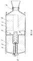
まず、第1図は、その2段推力型ロケットモータの一例を示す組立図である。第2図は、それに用いられる隔膜の組立前の外観図であり、第3図は、それに用いられる第1燃焼室、第2燃焼室および継ぎ手の連結部を示す拡大図であり、第4図は、それに用いられるイグナイタを示す拡大図であり、第5図は、その別形態を示す拡大図である。
第6図は、本発明の2段推力型ロケットモータの他の実施態様を示す組立図であり、第7図、第8図はこれに用いられるイグナイタを示す拡大図である。
Embodiments of the present invention will be described below with reference to the drawings.
1 to 5 are diagrams showing an example of an embodiment of the reference invention, and FIGS. 6 to 8 are diagrams showing an example of the present invention.
First, FIG. 1 is an assembly view showing an example of a 2-stage thrust rocket motor of that. Figure 2 is an external view of a front assembly of the membrane used therefor, Fig. 3, the first combustion chamber to be used therefor is an enlarged view showing the connecting portion of the second combustion chamber and fittings, the 4 Figure is an enlarged view showing the igniter used therein, FIG. 5 is an enlarged view showing the another embodiment.
FIG. 6 is an assembly view showing another embodiment of the two-stage thrust rocket motor of the present invention, and FIGS. 7 and 8 are enlarged views showing an igniter used therefor.
第1図〜第5図において、第1燃焼室1および第2燃焼室2は継ぎ手3とボルトの結合により直列に連結されている。第1燃焼室1の後端には噴射ノズル4が取り付けられている。第1燃焼室1、第2燃焼室2および継ぎ手3の内面には断熱材5が貼付けられ、その内部に前後に貫通する中空部を有する第1推進薬6と、前後に貫通する中空部を有する第2推進薬7がそれぞれ配設されている。
また第1点火用筐体12と第2点火用筐体13とを直列に連結したイグナイタ8は第2燃焼室2の前方部分にボルトにより取り付けられている。
1 to 5, the
The
さらに本例の場合、第1推進薬6と第2推進薬7との間には、ロケットモータ胴部中央付近の円周全体で外周端部が第2燃焼室2と継ぎ手3の結合部で固定され、第1点火用筐体12と第2点火用筐体13との間で内周端部が固定された隔膜9が第1推進薬6と第2推進薬7とを隔絶するように配設されている。
この隔膜9の外周端部は、第1燃焼室1と第2燃焼室2との結合部や、第1燃焼室1と継ぎ手3との結合部で固定されていてもよい。
また、この隔膜9は、第1点火薬10の発生ガスおよび第1推進薬6の燃焼ガスでは破断或いは消失せず、第2推進薬7の燃焼ガスおよび第2点火薬11の発生ガスで破断あるいは消失すると共に、第2点火薬11が発火する前に第2推進薬7が着火しないようなものでなければならない。
Further, in the case of this example, between the
The outer peripheral end of the
Further, the
このような隔膜9は、第2図で示すような形状を有するもので、その組成としてはEPDMゴム、シリコーンゴム、ケブラ繊維などの有機繊維を含有するEPDMゴムもしくはシリコーンゴムや、カーボン繊維などの無機繊維を含有するシリコーンゴムもしくはEPDMゴムなどが適用可能である。
これらの中では、第1推進薬の燃焼ガスにより燃焼消失しにくく、強度も高い有機繊維あるいは無機繊維含有のシリコーンゴムが隔膜組成としては好ましい。また第2図のような形状は例えばプレス成形により成形される。
Such a
Among these, organic fiber or inorganic fiber-containing silicone rubber which is difficult to burn and disappear with the combustion gas of the first propellant and has high strength is preferable as the diaphragm composition. The shape as shown in FIG. 2 is formed by press molding, for example.
第3図は、第1燃焼室1、第2燃焼室2および継ぎ手3の結合部を示しているが、第1燃焼室1と継ぎ手3、および第2燃焼室2と継ぎ手3はそれぞれボルトにより結合されている。第2燃焼室2と継ぎ手3とを結合する際に、第2図に示した隔膜9はその外周端を第2燃焼室2の溝部に嵌め込んだ状態で、第2燃焼室2と継ぎ手3の両方から押さえる状態で取り付けられる。
この際、継ぎ手3と隔膜9、および隔膜9と第2燃焼室2の接触部の気密性を確保するため接触部に接着剤を塗布し接着することができる。例えば隔膜組成が有機繊維または無機繊維を含有するシリコーンゴムの場合、シリコーン系の接着剤が適用される。
FIG. 3 shows a connecting portion of the
At this time, an adhesive can be applied and bonded to the contact portion in order to ensure the airtightness of the joint portion and the
第4図は、イグナイタ8の拡大図である。
図中、第1点火薬10は第1推進薬6を、第2点火薬11は第2推進薬7をそれぞれ選択的に着火させる点火薬である。それぞれ壁面に複数の貫通孔を有する、アルミニウムなどの金属で作られた円筒状の第1点火用筐体12、第2点火用筐体13中に点火薬がそれぞれ装填されており、第1点火用筐体12は第1封鎖体14に、第2点火用筐体13は第2封鎖体15にそれぞれネジで結合されている。
FIG. 4 is an enlarged view of the
In the figure, the first igniting
第1封鎖体14には第1イニシエータ16が、第2封鎖体15には第2イニシエータ17がそれぞれ取り付けられ、第2封鎖体15は第2燃焼室2の前方部分にボルトで結合され、第1封鎖体14は第2点火用筐体13にネジで結合されている。
A
第1イニシエータ16の脚線は、例えば圧着端子50により機械的・電気的に結合される。そして圧着端子50に連結された脚線18は第2点火用筐体13の中を貫通し第2点火用筐体13の前方側端部に空けられた第2封鎖体15の孔から第2点火用筐体13の外部に取り出されている。脚線18と第2封鎖体15との間には、例えばガラスハーメチックシール19により気密性が保持されている。
The leg of the
また第1封鎖体14と第2点火用筐体13とはネジで結合する際、隔膜9は第1封鎖体14と第2点火用筐体13との間に挟み込み、両面から押さえられるような状態で内周端が固定される。
この際、隔膜9と第1封鎖体14の接触部、および隔膜9と第2点火用筐体13の接触部の気密性を確保するために接触部を接着剤で接着することができる。例えば隔膜組成が有機繊維または無機繊維を含有するシリコーンゴムの場合、シリコーン系の接着剤が適用される。
Further, when the
At this time, the contact portion can be adhered with an adhesive to ensure the airtightness of the contact portion between the
次に、前記隔膜9について、その組成と厚みと配置する位置の設定方法について説明する。隔膜9は第1推進薬6の燃焼ガス圧力により第2点火用筐体13と第2推進薬7で形成される空間内で変形するが、第2推進薬7に接触した後は第2推進薬7の変形に対する反発作用により隔膜9の変形は抑えられる。この際、初期の隔膜9の変形が大きいほど隔膜9の内部に発生する引張応力は大きくなり、この引張応力が隔膜9の材質の許容破断応力より大きくなると、その時点で隔膜9は破断することになる。
この原理に基づき引張応力が隔膜9の許容破断応力未満になるように、隔膜9の組成と厚み、隔膜9が変形する空間を決定する第2点火用筐体13の外形形状と第2推進薬7の内面形状に対する隔膜9の配置が設定される。
設定の際に必要となる隔膜9に発生する引張応力は、従来より使用されている応力解析プログラムによる計算により求めることができる。
Next, a method for setting the composition, thickness, and position of the
Based on this principle, the outer shape of the
The tensile stress generated in the
前記の空間の大きさを制限するために、必要に応じて第5図に示すように、第2点火用筐体13の一部として第2点火用筐体13にネジ結合により取り付けた該筐体と同一材料の構造体20と、第1封鎖体14とにより隔膜9を固定する形態であってもよい。
前記の方法により、第1推進薬6の燃焼ガス圧力を受けても破断しない隔膜9を使用することができる。
In order to limit the size of the space, as shown in FIG. 5, the housing attached to the
By the above method, it is possible to use the
隔膜9はさらに第2推進薬7を着火させる所定時刻まで第2推進薬7側の面の温度が、第2推進薬7の着火温度未満になるように組成、厚み、配置が設定される必要がある。第2推進薬7が着火される所定の時刻まで隔膜9の第2推進薬7側の面がその着火温度未満になるように隔膜9の組成、厚み、配置は従来より使用されている熱解析プログラムによる計算により設定できる。
The composition, thickness, and arrangement of the
本例の隔膜9の組成、厚み、配置は説明したように破断しない条件と温度の条件の両方を満足するものとして設定される。例えば外径が200mm、長さが2000mmの形状を有する第1推進薬6および第2推進薬7として、ポリブタジエンバインダと過塩素酸アンモニウムを主成分とするコンポジット推進薬を使用した2段推力型ロケットモータの場合、隔膜の厚みは1mmから20mmの間の値に設定される。
The composition, thickness, and arrangement of the
以上のようにして、第1の例の2段推力型ロケットモータは完成するが、隔膜9の厚さ、組成、配置によっては、保管時の自重あるいは輸送時に発生する振動などにより第1燃焼室6側に大きく変形し、設定した隔膜9の厚み、配置が変わってしまう場合がある。
これを防止するために、隔膜9が第1燃焼室1側に大きく変形しないように、必要に応じて、第2推進薬7の表面、即ち、第2推進薬7の後部端面または第2推進薬7の中空部壁面の第1燃焼室側表面において隔膜9の一部若しくは全面で接着することも行われる。
この場合は、第2推進薬7の表面に接着剤を塗布し、隔膜9を第2推進薬7に接着した後、隔膜9の内周端を第1封鎖体14と第2点火用筐体13との間に固定する。
As described above, the two-stage thrust type rocket motor of the first example is completed. However, depending on the thickness, composition, and arrangement of the
In order to prevent this, the surface of the
In this case, an adhesive is applied to the surface of the
隔膜9と第2推進薬7を接着する接着剤は、第2推進薬7および隔膜9の組成により選定される。例えば、第2推進薬7がポリブタジエンバインダと過塩素酸アンモニウムを主成分とするコンポジット推進薬で、隔膜9としてケブラを含有するEPDMゴムを使用する場合であれば、接着剤としては、例えばエポキシ系接着剤が選定される。
The adhesive that bonds the
また2段推力型ロケットモータの大きさによっては第1点火薬、第2点火薬の薬量が大きくなり、イニシエータからの発火ガスのみでは、点火薬を確実に着火させることができなくなる場合がある。その場合には封鎖体内に、イニシエータの発火ガスにより発火し、点火薬を着火させる助装薬を配設する形態をとることで点火薬の着火、ひいては推進薬の着火を確実に行うことが可能となる。 In addition, depending on the size of the two-stage thrust rocket motor, the amounts of the first and second igniters may increase, and the igniter may not be reliably ignited with only the ignition gas from the initiator. . In that case, it is possible to reliably ignite the igniting agent and eventually the propellant by arranging an auxiliary agent that ignites with the ignition gas of the initiator and ignites the igniting agent in the sealed body. It becomes.
次に本例の作用について説明する。
第1イニシエータ16に通電され第1点火薬10の発火ガスにより第1推進薬6が燃焼を開始する。この際、発生する第1推進薬6の燃焼ガス圧力により隔膜9は第2燃焼室2側に変形するが、隔膜9に発生する引張応力は隔膜材質の許容破断応力以下になるように設定されているので、第1推進薬6の燃焼中に破断することはない。また隔膜9により第2推進薬7側の面の温度が第2推進薬7の着火温度未満となるように設定されているので、第1推進薬6の燃焼中に第2推進薬7が着火することはない。これらの作用により第1推進薬6の燃焼による第1段の推力が発生する。
第1推進薬6の燃焼が終了して第1段推力が終了した後、第2段推力を発生させる所定の時刻まで隔膜9の第2推進薬7側の面は、第2推進薬7の着火温度未満であるように設定されているので、その時間まで第2推進薬7が着火し燃焼を開始することはない。すなわち第2段の推力が予期しない時点で発生することはない。
Next, the operation of this example will be described.
When the
After the combustion of the
所定の時刻に第2イニシエータ17に対して通電されると、第2点火薬11が発火し、その発火ガスが第2点火用筐体13壁面の貫通孔から放出され、第2推進薬7が着火する。
第2推進薬7の発生する燃焼ガス圧により隔膜9は、第1推進薬6のなくなった第1燃焼室1の空間に大きく変形する。この変形により隔膜9は内部に発生する引張応力が許容破断応力以上になった時点で破断する。あるいは破断する前に第2点火薬11および第2推進薬7の燃焼ガスの熱で隔膜9は消失する。この破断した個所あるいは消失した個所から第2推進薬7の燃焼ガスは第1燃焼室に流入し、その後、噴射ノズル4から噴射され第2段の推力が発生する。
この際、初期において第2点火薬11の発火ガスは第2推進薬7の広い面積を着火させるので、第2推進薬7の燃焼ガス量の発生速度が速くなる。即ち、圧力の上昇が速くなるために隔膜9の破断までの時間は短くなり、第2段の推力の立ち上がりはイニシエータ17の通電から短時間で達成可能となる。その後は、第2推進薬7の燃焼終了まで第2段推力が発生する。
When the
Due to the combustion gas pressure generated by the
At this time, since the ignition gas of the
第6図は、本発明の別例を示す2段推力型ロケットモータの組立図である。本例は前記の第1の例とはイグナイタの構造が異なっているのみであり、その他の構造は同じであることから以下イグナイタについて説明する。
第7図は、イグナイタ周辺の拡大図である。この例では、第1点火薬10、第2点火薬11は壁面に1個以上の貫通孔を有する、例えばアルミニウムなどの金属製の第1点火用筐体12、第2点火用筐体13にそれぞれ装填されている。第2点火用筐体13は第2燃焼室2の前方部分にボルトで結合可能なフランジを有する第2封鎖体15にネジで結合されている。この第2封鎖体15には第2点火薬11を点火するための助装薬21が円周状の溝に装填され、この助装薬21を発火させるためのイニシエータ22が取り付けられている。
FIG. 6 is an assembly drawing of a two-stage thrust type rocket motor showing another example of the present invention. Since this example is different from the first example only in the structure of the igniter and the other structures are the same, the igniter will be described below.
FIG. 7 is an enlarged view around the igniter. In this example, the first igniting
第8図は、前記イグナイタの一部拡大図である。
第2封鎖体15には、第1点火薬10を発火するための助装薬24が装填された、例えばアルミニウムなどの金属製の管体23がネジで結合され、助装薬24を着火するためのイニシエータ26が取り付けられている。管体23は第2点火薬11が装填されている第2点火用筐体13内を貫通し、第1点火薬10が装填された第1点火用筐体12内にその前方部分が位置するように取り付けられている。管体23は第1点火用筐体12に位置する壁面に複数の貫通孔を有している。第1段推力の発生時に第1点火薬10の発火ガスおよび第1推進薬6の燃焼ガスの第2点火用筐体13内への流入による第2点火薬11の予期しない発火を防ぐため、第1封鎖体14と管体23の勘合部には、ニトリルゴム、フッ素ゴムやシリコンゴムなどのオーリング25が取り付けられている。第1点火用筐体12と第1封鎖体14、第2点火用筐体13と第2封鎖体15、第1封鎖体14と第2点火用筐体13の結合構造、隔膜9の固定方法は前記第1の例と同じである。
FIG. 8 is a partially enlarged view of the igniter.
A
次にこの例の作用について説明する。
イニシエータ26が通電され発火することで、助装薬24が発火する。助装薬24の発火ガスは管体23の第1点火用筐体12に位置する壁面の貫通孔から噴出し、第1点火薬10を発火し、その発火ガスは第1点火用筐体12の壁面にある貫通孔から噴出し、第1推進薬6を着火して第1推進薬6は燃焼を開始する。すなわち第1段の推力が発生する。第1推進薬6の燃焼が終了後、所定の時刻にイニシエータ22に対して通電され、その発火ガスにより助装薬21が発火し、その発火ガスにより第2点火薬11が発火する。その発火ガスは第2点火用筐体13の壁面にある貫通孔から噴出し、第2推進薬7を着火し、その燃焼ガスの圧力あるいは熱により隔膜9が破断あるいは消失することで、第2推進薬7の燃焼ガスは第1燃焼室1に流入し、その後、噴射ノズル4から噴射され第2段の推力が発生する。
Next, the operation of this example will be described.
When the
以上説明してきたように、本発明によれば第1推進薬が燃焼している状態では、第2推進薬と第1推進薬との間に配置された隔膜は破断および消失することがなく、さらに第2推進薬を着火させる所定の時刻まで隔膜の第2推進薬側の表面温度は、第2推進薬の着火温度未満に抑えられているので、第2推進薬はそれまで燃焼を開始することがない。
次に第2点火薬を発火させ、その発火ガスにより第2推進薬が着火し燃焼を開始する。このとき、第2点火薬の発火ガスおよび第2推進薬の燃焼ガスの圧力、あるいは熱により隔膜は破断あるいは消失し、その部分から第2推進薬の燃焼ガスは第1燃焼室に流入し、噴射ノズルから噴射される。以上により第1段推力が第1推進薬の燃焼により発生し、第2段推力が所定の時刻に開始される第2推進薬の燃焼により発生する2段推力型ロケットモータが得られる。
As explained above, according to the present invention, in the state where the first propellant is burning, the diaphragm disposed between the second propellant and the first propellant does not break and disappear, Furthermore, since the surface temperature of the second propellant side of the diaphragm is kept below the ignition temperature of the second propellant until a predetermined time at which the second propellant is ignited, the second propellant starts to combust until then. There is nothing.
Next, the second igniter is ignited, and the second propellant is ignited by the ignited gas and combustion is started. At this time, the diaphragm breaks or disappears due to the pressure of the ignition gas of the second igniting agent and the combustion gas of the second propellant, or heat, and the combustion gas of the second propellant flows into the first combustion chamber from that portion, Sprayed from the spray nozzle. Thus, a two-stage thrust type rocket motor is obtained in which the first stage thrust is generated by the combustion of the first propellant and the second stage thrust is generated by the combustion of the second propellant that is started at a predetermined time.
1:第1燃焼室、2:第2燃焼室、3:継ぎ手、4:噴射ノズル、5:断熱材、6:第1推進薬、7:第2推進薬、8:イグナイタ、9:隔膜、10:第1点火薬、11:第2点火薬、12:第1点火用筐体、13:第2点火用筐体、14:第1封鎖体、15:第2封鎖体、16:第1イニシエータ、17:第2イニシエータ、18:脚線、19:ガラスハーメチックシール、20:構造体、21:第2助装薬、22:第2イニシエータ、23:管体、24:第1助装薬、25:オーリング、26:第1イニシエータ、30:噴射ノズル、31:ポーラボス、32:ポーラボス、33:燃焼室、34:第1推進薬、35:第2推進薬、36:前方絶縁体、37:隔膜、38:推進薬支持体、39:イグナイタ封鎖体、40:イグナイタケース、41:第1点火薬、42:第2点火薬、43:円環状チャンバ、50:圧着端子、51:ノズルポート。 1: first combustion chamber, 2: second combustion chamber, 3: joint, 4: injection nozzle, 5: heat insulating material, 6: first propellant, 7: second propellant, 8: igniter, 9: diaphragm, 10: first igniter, 11: second igniter, 12: first ignition housing, 13: second ignition housing, 14: first sealing body, 15: second sealing body, 16: first Initiator, 17: second initiator, 18: leg wire, 19: glass hermetic seal, 20: structure, 21: second assisting agent, 22: second initiator, 23: tubular body, 24: first assisting agent , 25: O-ring, 26: first initiator, 30: injection nozzle, 31: Porlabus, 32: Porlabus, 33: combustion chamber, 34: first propellant, 35: second propellant, 36: forward insulator, 37: diaphragm, 38: propellant support, 39: igniter blockade, 40: igniter case 41: first igniter, 42: second igniter, 43: annular chamber, 50: crimp terminal, 51: a nozzle port.
Claims (4)
該噴射ノズル4から前方に第1燃焼室1および第2燃焼室2がこの順序で直接または継ぎ手3を介して直列に結合する状態で配設され、
第1燃焼室内に前後に貫通する中空部を有する第1推進薬6、第2燃焼室内に前後に貫通する中空部を有する第2推進薬7がそれぞれ配設され、
第1推進薬6を選択的に発火させる位置の壁面に1個以上の貫通孔と、第1点火用筐体12の前方側端部に第1点火薬10を発火させる機構が取り付けられた第1封鎖体14とを有し、かつ第1点火薬10を内部に装填した第1点火用筐体12が第1燃焼室内の前後中心軸上に配設され、
第2推進薬7の中空部壁面を直接発火させる位置で壁面に1個以上の貫通孔と、第2点火用筐体13の前方側端部に第2点火薬11を発火させる機構が取り付けられた第2封鎖体15とを有し、かつ第2点火薬11を内部に装填した第2点火用筐体13が第2推進薬7の中空部に配設され、
ロケットモータ胴部の円周全体で外周端部が固定され、第1点火用筐体12と第2点火用筐体13との間で内周端部が固定された隔膜9が第1推進薬6と第2推進薬7とを隔絶するように配設され、
該隔膜9が第1点火薬10の発生ガスおよび第1推進薬6の燃焼ガスでは破断あるいは消失せず、第2推進薬7の燃焼ガスおよび第2点火薬11の発生ガスで破断あるいは消失する2段推力型ロケットモータにおいて、第1点火薬10を発火させる機構が第1イニシエータ26と、第2封鎖体15、第2点火用筐体13およびそれと連結された第1封鎖体14の全てを貫通して第1点火用筐体12内部まで伸び出ており、かつイニシエータ26の着火を伝搬する助装薬24を内部に備えた管体23とからなることを特徴とする2段推力型ロケットモータ。 An injection nozzle 4 is arranged at the rear,
The first combustion chamber 1 and the second combustion chamber 2 are disposed in front of the injection nozzle 4 in such a state that the first combustion chamber 1 and the second combustion chamber 2 are connected in series in this order directly or via the joint 3.
A first propellant 6 having a hollow portion penetrating front and rear in the first combustion chamber and a second propellant 7 having a hollow portion penetrating front and rear in the second combustion chamber, respectively;
One or more through holes are provided in the wall surface of the position where the first propellant 6 is selectively ignited, and a mechanism for igniting the first igniter 10 is attached to the front end of the first ignition housing 12. A first ignition housing 12 having a first sealing body 14 and loaded with a first igniting agent 10 is disposed on a front and rear central axis in the first combustion chamber,
One or more through holes are provided in the wall surface at a position where the hollow wall surface of the second propellant 7 is directly ignited, and a mechanism for igniting the second igniter 11 is attached to the front end of the second ignition housing 13. A second ignition housing 13 having the second sealing body 15 and the second ignition powder 11 loaded therein is disposed in the hollow portion of the second propellant 7;
A diaphragm 9 having an outer peripheral end fixed on the entire circumference of the rocket motor body and an inner peripheral end fixed between the first ignition housing 12 and the second ignition housing 13 is a first propellant. 6 and the second propellant 7 are disposed to be isolated from each other,
The diaphragm 9 is not broken or lost by the gas generated from the first igniter 10 and the combustion gas from the first propellant 6, but is broken or lost by the combustion gas from the second propellant 7 and the gas generated from the second igniter 11. In the two-stage thrust type rocket motor, the mechanism for igniting the first igniting agent 10 includes all of the first initiator 26, the second sealing body 15, the second ignition housing 13 and the first sealing body 14 connected thereto. A two-stage thrust rocket characterized by comprising a tubular body 23 that penetrates and extends to the inside of the first ignition housing 12 and that has an auxiliary agent 24 that propagates ignition of the initiator 26 inside. motor.
Priority Applications (1)
| Application Number | Priority Date | Filing Date | Title |
|---|---|---|---|
| JP2003417041A JP4179157B2 (en) | 2003-12-15 | 2003-12-15 | Two-stage thrust rocket motor |
Applications Claiming Priority (1)
| Application Number | Priority Date | Filing Date | Title |
|---|---|---|---|
| JP2003417041A JP4179157B2 (en) | 2003-12-15 | 2003-12-15 | Two-stage thrust rocket motor |
Publications (3)
| Publication Number | Publication Date |
|---|---|
| JP2005171970A JP2005171970A (en) | 2005-06-30 |
| JP2005171970A5 JP2005171970A5 (en) | 2005-10-27 |
| JP4179157B2 true JP4179157B2 (en) | 2008-11-12 |
Family
ID=34736071
Family Applications (1)
| Application Number | Title | Priority Date | Filing Date |
|---|---|---|---|
| JP2003417041A Expired - Fee Related JP4179157B2 (en) | 2003-12-15 | 2003-12-15 | Two-stage thrust rocket motor |
Country Status (1)
| Country | Link |
|---|---|
| JP (1) | JP4179157B2 (en) |
Cited By (4)
| Publication number | Priority date | Publication date | Assignee | Title |
|---|---|---|---|---|
| US9371801B2 (en) | 2012-06-12 | 2016-06-21 | Asahi Kasei Kabushiki Kaisha | Ignition device for two-pulse rocket motor with thermal barrier membrane |
| KR20170141495A (en) * | 2016-06-15 | 2017-12-26 | 주식회사 한화 | Disc type igniter mount assembly and installing method thereof |
| KR101878552B1 (en) * | 2016-06-15 | 2018-07-13 | 주식회사 한화 | Nozzle Closure Type Igniter Mount And installing Method Thereof |
| KR102449276B1 (en) | 2022-04-27 | 2022-09-28 | 국방과학연구소 | Two-stage pulse rocket motor for high altitude firing test |
Families Citing this family (11)
| Publication number | Priority date | Publication date | Assignee | Title |
|---|---|---|---|---|
| KR100823575B1 (en) | 2007-04-05 | 2008-04-21 | 국방과학연구소 | Propellant assembly for solid rocket |
| JP4719182B2 (en) | 2007-05-14 | 2011-07-06 | 三菱重工業株式会社 | 2-pulse rocket motor |
| JP5602094B2 (en) | 2011-06-08 | 2014-10-08 | 三菱重工業株式会社 | Multi-pulse rocket motor and its pulse unit |
| JP5860705B2 (en) * | 2011-06-24 | 2016-02-16 | 株式会社Ihiエアロスペース | Pulse rocket motor |
| JP5602106B2 (en) | 2011-07-14 | 2014-10-08 | 三菱重工業株式会社 | Combustion gas supply control mechanism |
| KR101192203B1 (en) | 2012-05-08 | 2012-10-17 | 국방과학연구소 | Propulsive equipment and rocket having the same |
| JP6307345B2 (en) * | 2014-05-14 | 2018-04-04 | 株式会社Ihiエアロスペース | Multi-pulse rocket motor and manufacturing method thereof |
| JP6291343B2 (en) * | 2014-05-14 | 2018-03-14 | 株式会社Ihiエアロスペース | Multi-pulse rocket motor |
| KR101494393B1 (en) * | 2014-05-23 | 2015-02-17 | 엘아이지넥스원 주식회사 | Dual thrust rocket propulsion machinery |
| CN107529585B (en) * | 2017-03-30 | 2023-05-05 | 内蒙动力机械研究所 | Melt film type partition plate suitable for multi-pulse solid rocket engine |
| KR101809873B1 (en) * | 2017-05-17 | 2017-12-15 | 국방과학연구소 | Multi ignition system |
-
2003
- 2003-12-15 JP JP2003417041A patent/JP4179157B2/en not_active Expired - Fee Related
Cited By (5)
| Publication number | Priority date | Publication date | Assignee | Title |
|---|---|---|---|---|
| US9371801B2 (en) | 2012-06-12 | 2016-06-21 | Asahi Kasei Kabushiki Kaisha | Ignition device for two-pulse rocket motor with thermal barrier membrane |
| KR20170141495A (en) * | 2016-06-15 | 2017-12-26 | 주식회사 한화 | Disc type igniter mount assembly and installing method thereof |
| KR101872587B1 (en) * | 2016-06-15 | 2018-06-28 | 주식회사 한화 | Disc type igniter mount assembly and installing method thereof |
| KR101878552B1 (en) * | 2016-06-15 | 2018-07-13 | 주식회사 한화 | Nozzle Closure Type Igniter Mount And installing Method Thereof |
| KR102449276B1 (en) | 2022-04-27 | 2022-09-28 | 국방과학연구소 | Two-stage pulse rocket motor for high altitude firing test |
Also Published As
| Publication number | Publication date |
|---|---|
| JP2005171970A (en) | 2005-06-30 |
Similar Documents
| Publication | Publication Date | Title |
|---|---|---|
| JP4179157B2 (en) | Two-stage thrust rocket motor | |
| US7357083B2 (en) | Initiator | |
| JP3231778B2 (en) | Case filled with two-pulse rocket motor of solid propellant, ignition device and method of manufacturing the same | |
| US7431337B2 (en) | Inflator for an air bag | |
| JP5216804B2 (en) | Portable guided bullet injection and separation device | |
| US20070119325A1 (en) | Energetic material initiation device utilizing exploding foil initiated ignition system with secondary explosive material | |
| US4956971A (en) | Solid propellant canister loaded multiple pulsed or staged rocket motor | |
| US10247139B2 (en) | Two-pulse gas generator and operation method thereof | |
| EP3527929A1 (en) | High explosive firing mechanism | |
| JP2006266198A (en) | Two-stage thrust control rocket motor | |
| JP6012278B2 (en) | Ignition device for diaphragm type 2 pulse rocket motor | |
| EP0118595A2 (en) | Weather seal arrangement for solid rocket motor igniters | |
| JP2005171970A5 (en) | ||
| JP5295354B2 (en) | Gas generator for automobile safety equipment | |
| JP4619813B2 (en) | Two-stage thrust rocket motor | |
| CN110985237A (en) | Connecting and fixing device for failure at high temperature based on memory alloy technology and application method | |
| JP5709259B2 (en) | Pulse rocket motor | |
| US4154141A (en) | Ultrafast, linearly-deflagration ignition system | |
| JPH0442538B2 (en) | ||
| US11067036B2 (en) | Combustor and jet engine having the same | |
| JP4619814B2 (en) | Two-stage thrust rocket motor | |
| US3204559A (en) | Rocket propellant charge igniter | |
| US5113763A (en) | Consumable igniter for a solid rocket motor | |
| US3616646A (en) | Forward or aft stress relief for a case bonded solid propellant | |
| JP2002211500A (en) | Coupling/decoupling device for booster rocket and rocket |
Legal Events
| Date | Code | Title | Description |
|---|---|---|---|
| A521 | Written amendment |
Free format text: JAPANESE INTERMEDIATE CODE: A523 Effective date: 20050830 |
|
| A621 | Written request for application examination |
Free format text: JAPANESE INTERMEDIATE CODE: A621 Effective date: 20050830 |
|
| A977 | Report on retrieval |
Free format text: JAPANESE INTERMEDIATE CODE: A971007 Effective date: 20080129 |
|
| A131 | Notification of reasons for refusal |
Free format text: JAPANESE INTERMEDIATE CODE: A131 Effective date: 20080513 |
|
| A521 | Written amendment |
Free format text: JAPANESE INTERMEDIATE CODE: A523 Effective date: 20080707 |
|
| TRDD | Decision of grant or rejection written | ||
| A01 | Written decision to grant a patent or to grant a registration (utility model) |
Free format text: JAPANESE INTERMEDIATE CODE: A01 Effective date: 20080805 |
|
| A01 | Written decision to grant a patent or to grant a registration (utility model) |
Free format text: JAPANESE INTERMEDIATE CODE: A01 |
|
| A61 | First payment of annual fees (during grant procedure) |
Free format text: JAPANESE INTERMEDIATE CODE: A61 Effective date: 20080818 |
|
| R150 | Certificate of patent or registration of utility model |
Free format text: JAPANESE INTERMEDIATE CODE: R150 |
|
| FPAY | Renewal fee payment (event date is renewal date of database) |
Free format text: PAYMENT UNTIL: 20110905 Year of fee payment: 3 |
|
| FPAY | Renewal fee payment (event date is renewal date of database) |
Free format text: PAYMENT UNTIL: 20120905 Year of fee payment: 4 |
|
| FPAY | Renewal fee payment (event date is renewal date of database) |
Free format text: PAYMENT UNTIL: 20130905 Year of fee payment: 5 |
|
| LAPS | Cancellation because of no payment of annual fees |