JP4177732B2 - Wiring and piping material packing equipment - Google Patents

Wiring and piping material packing equipment Download PDF

Info

Publication number
JP4177732B2
JP4177732B2 JP2003288148A JP2003288148A JP4177732B2 JP 4177732 B2 JP4177732 B2 JP 4177732B2 JP 2003288148 A JP2003288148 A JP 2003288148A JP 2003288148 A JP2003288148 A JP 2003288148A JP 4177732 B2 JP4177732 B2 JP 4177732B2
Authority
JP
Japan
Prior art keywords
wiring
cardboard box
bundle
side wall
wound
Prior art date
Legal status (The legal status is an assumption and is not a legal conclusion. Google has not performed a legal analysis and makes no representation as to the accuracy of the status listed.)
Expired - Fee Related
Application number
JP2003288148A
Other languages
Japanese (ja)
Other versions
JP2005053678A (en
Inventor
茂之 後藤
Current Assignee (The listed assignees may be inaccurate. Google has not performed a legal analysis and makes no representation or warranty as to the accuracy of the list.)
Mirai Kogyo KK
Original Assignee
Mirai Kogyo KK
Priority date (The priority date is an assumption and is not a legal conclusion. Google has not performed a legal analysis and makes no representation as to the accuracy of the date listed.)
Filing date
Publication date
Application filed by Mirai Kogyo KK filed Critical Mirai Kogyo KK
Priority to JP2003288148A priority Critical patent/JP4177732B2/en
Publication of JP2005053678A publication Critical patent/JP2005053678A/en
Application granted granted Critical
Publication of JP4177732B2 publication Critical patent/JP4177732B2/en
Anticipated expiration legal-status Critical
Expired - Fee Related legal-status Critical Current

Links

Images

Description

この発明は、配線・配管材を梱包する、配線・配管材の梱包装置に関するものである。   The present invention relates to a wiring / piping material packing apparatus for packing wiring / piping material.

従来より、段ボール箱内で、巻回された配線・配管材の巻回束を支える回動部材を、巻回束とともに回動させて、配線・配管材を段ボール箱の外に引き出す梱包装置が考えられていた。この梱包装置は、前記回動部材を回動可能に支持すべく、段ボール箱における、巻回束の各側面と対向する左右の側壁のそれぞれに、支持軸が互いに独立して設けられていた。   Conventionally, a packaging device that rotates a rotating member that supports a wound bundle of wiring / piping material wound in a cardboard box together with the wound bundle, and pulls the wiring / piping material out of the cardboard box. It was thought. In this packaging device, support shafts are provided independently of each other on the left and right side walls of the corrugated cardboard box facing the side surfaces of the wound bundle in order to rotatably support the rotating member.

しかし、かかる梱包装置にあっては、重量の大きい配線・配管材の巻回束を回動部材、さらには支持軸に支持させた際、その荷重により、段ボール箱の左右の側壁は、外方に広がるように変形し、そして、回動部材の回動にともなって歪みが生じ、左右の側壁に設けられた支持軸の軸がずれて、回動部材が円滑に回動できないという問題が生じた。   However, in such a packing device, when the heavy bundle of wiring / piping material is supported on the rotating member and further on the support shaft, the left and right side walls of the cardboard box are moved outward by the load. And the distortion of the rotating member is caused by the rotation of the rotating member, the support shafts provided on the left and right side walls are displaced, and the rotating member cannot be smoothly rotated. It was.

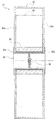
これに対して、左右の支持軸を連結して、1つの軸部材とした、梱包装置も考えられていた(例えば、特許文献1参照)。この梱包装置31は、図14に示すように、段ボール箱32と、その段ボール箱32内において、テールコード33が巻かれた、回動部材としての巻芯34と、その巻芯34を軸支する軸部材35とから構成されていた。ここで、軸部材35は、左右の支持軸35a、35aを備え、それら支持軸35a、35aが中央で、連結具36により結合されていた。このように、この梱包装置31によると、左右の支持軸35a、35aが離間しないように結合されているため、重量の大きなテールコード33(配線・配管材)を収容した場合であっても、段ボール箱32の左右の側壁32a、32aが外方に広がることはなく、また、左右の支持軸35a、35aもずれる虞はなかった。   On the other hand, the packing apparatus which connected the support shaft on either side and made it one shaft member was also considered (for example, refer patent document 1). As shown in FIG. 14, the packing device 31 includes a cardboard box 32, a core 34 as a rotating member around which the tail cord 33 is wound, and the core 34 is pivotally supported in the cardboard box 32. It was comprised from the shaft member 35 to do. Here, the shaft member 35 includes left and right support shafts 35 a and 35 a, and the support shafts 35 a and 35 a are coupled to each other at the center by a connector 36. Thus, according to this packing device 31, since the left and right support shafts 35a, 35a are coupled so as not to be separated from each other, even when a heavy tail cord 33 (wiring / piping material) is accommodated, The left and right side walls 32a, 32a of the cardboard box 32 did not spread outward, and there was no possibility that the left and right support shafts 35a, 35a would shift.

特開平4−39271号公報JP-A-4-39271

ところが、前記従来の梱包装置31のように、左右の側壁32a、32aが外方に全く広がらない構成にあっては、軸部材35と巻芯34との間のクリアランスにより、テールコード33を引き出す際に、回動部材としての巻芯34およびテールコード33が、若干傾くとともに、その傾きにより、巻芯34およびテールコード33は、段ボール箱32の内面に摺接して、円滑に回動しない虞があった。   However, when the left and right side walls 32a and 32a do not spread outward at all as in the conventional packing device 31, the tail cord 33 is pulled out by the clearance between the shaft member 35 and the core 34. At this time, the winding core 34 and the tail cord 33 as the rotating members are slightly inclined, and the inclination may cause the winding core 34 and the tail cord 33 to slide in contact with the inner surface of the cardboard box 32 and not smoothly rotate. was there.

この発明は、上記した従来の欠点を解決するためになされたものであり、その目的とするところは、回動部材を円滑に回動させることができる、配線・配管材の梱包装置を提供することにある。   The present invention has been made to solve the above-described conventional drawbacks, and an object of the present invention is to provide a wiring / piping material packing apparatus capable of smoothly rotating a rotating member. There is.

この発明に係る配線・配管材の梱包装置は、前記目的を達成するために、次の構成からなる。すなわち、
請求項1に記載の発明に係る配線・配管材の梱包装置は、周回状に巻回された配線・配管材の巻回束を梱包する梱包装置である。この梱包装置は、前記巻回束を収容するとともに、前記配線・配管材をその端部から順に外に引き出すための引出部が備わる、段ボール箱体と、前記段ボール箱体に収容されて、前記巻回束を支える回動部材と、前記段ボール箱体における、前記巻回束の各側面と対向する側壁に、渡されるようにして取り付けられて、前記回動部材が前記巻回束とともにその巻回束の周方向に回動可能となるよう支持する軸部材と、を備える。ここで、前記軸部材は、少なくとも二つの分割体によって形成され、かつ、前記段ボール箱体の前記各側壁には、前記分割体がそれぞれ固着されている。そして、前記軸部材は、前記各分割体が互いの軸心がずれることなくその軸方向に相対移動するようにして、前記軸方向に伸長可能となっており、前記軸部材が前記軸方向に伸長することで、前記段ボール箱体の前記側壁が外方に広がる。
The wiring / pipe material packaging apparatus according to the present invention has the following configuration in order to achieve the object. That is,
The wiring / pipe material packing apparatus according to the first aspect of the present invention is a packing apparatus for packing a wound bundle of wiring / piping material wound in a circular shape. The packing device accommodates the wound bundle and is provided with a cardboard box body provided with a lead-out portion for sequentially pulling out the wiring / pipe material from the end portion thereof, and is accommodated in the cardboard box body, A rotating member that supports the wound bundle, and is attached to a side wall of the corrugated cardboard box facing each side surface of the wound bundle so as to be passed, and the rotating member is wound together with the wound bundle. A shaft member that is supported so as to be rotatable in the circumferential direction of the bundle. Here, the shaft member is formed by at least two divided bodies, and the divided bodies are respectively fixed to the side walls of the cardboard box body. Then, the shaft member, prior SL as each divided body is relatively moved in the axial direction without mutual axis is shifted, has a extendable in the axial direction, the shaft member is the axial direction The side wall of the cardboard box body spreads outward.

このように、この梱包装置は、段ボール箱体を備えている。この段ボール箱体には、周回状に巻回された配線・配管材の巻回束と、その巻回束を支える回動部材が収容される。そして、軸部材が、段ボール箱体における、巻回束の各側面と対向する側壁に、渡されるようにして取り付けられる。この軸部材は、回動部材が前記巻回束とともにその巻回束の周方向に回動可能となるように支持するものであり、こうして、段ボール箱体に収容された巻回束は、その巻回束の周方向に回動可能となる。ところで、巻回束となった配線・配管材は、段ボール箱体に収容されて、保管されたり運搬されたりする。そして、配線・配管材を配線あるいは配管する場合には、段ボール箱体内の配線・配管材を、その端部から順に、段ボール箱体に備わる引出部を通して、外に引き出すが、この引き出しに伴って、段ボール箱体内の巻回束が解かれるようにして、回動部材とともにその巻回束が回動する。ここで、軸部材は、各分割体が互いの軸心がすれることなくその軸方向に相対移動するようにして、軸方向に伸長可能となっており、これにより、配線・配管材を引き出す力あるいは、配線・配管材の自重等が、段ボール箱体に作用すると、軸部材がその軸方向に伸長することで、段ボール箱体の側壁は、外方に広がる。したがって、配線・配管材の引き出しによって、回動部材が軸部材とのクリアランス等により傾いても、その回動部材は、側壁の内面に接触しないか、あるいは、側壁の内面への押圧力が軽減される。しかも、段ボール箱体の各側壁に、前記分割体がそれぞれ固着されて取り付けられることで、配線・配管材を引き出す力とか、配線・配管材の自重等が、分割体から側壁に安定して伝わる。したがって、側壁における、分割体が取り付けられる部分の変形が抑えられる。なお、回動部材が巻回束とともに回動するとは、回動部材が巻回束と一体となって回動する場合は勿論、回動部材が巻回束よりも遅れて回動する場合をも含むものである。 Thus, this packing apparatus is provided with a cardboard box. In this corrugated cardboard box, a wound bundle of wiring / pipe material wound in a circular shape and a rotating member that supports the wound bundle are accommodated. And a shaft member is attached so that it may be passed to the side wall facing each side surface of a wound bundle in a cardboard box. The shaft member supports the rotating member so as to be rotatable in the circumferential direction of the winding bundle together with the winding bundle. Thus, the winding bundle housed in the cardboard box body is It becomes possible to rotate in the circumferential direction of the wound bundle. By the way, the wiring / piping material that has become a wound bundle is stored in a cardboard box and stored or transported. And when wiring or piping the wiring / piping material, the wiring / piping material in the cardboard box body is drawn out from the end through the lead-out part provided in the cardboard box body. The wound bundle is rotated together with the rotating member so that the wound bundle in the cardboard box is released. Here, the shaft member, as each divided body is relatively moved in the axial direction without rub each other's axis, has a extensible in the axial direction, by this, the wiring and piping material When the pulling-out force or the weight of the wiring / pipe material acts on the cardboard box body, the shaft member extends in the axial direction, so that the side wall of the cardboard box body spreads outward. Therefore, even if the rotating member is tilted due to the clearance with the shaft member or the like by pulling out the wiring / pipe material, the rotating member does not contact the inner surface of the side wall or the pressing force to the inner surface of the side wall is reduced. Is done. Moreover, by attaching the divided body to each side wall of the corrugated cardboard box, the force for pulling out the wiring / piping material, the weight of the wiring / piping material, etc. is stably transmitted from the divided body to the side wall. . Therefore, deformation of the portion of the side wall to which the divided body is attached is suppressed. Note that the rotation member rotates together with the winding bundle means that the rotation member rotates after the winding bundle as well as the rotation member integrally rotating with the winding bundle. Is also included.

また、請求項2に記載の発明に係る配線・配管材の梱包装置のように、請求項1に記載の梱包装置において、前記各分割体は、前記巻回束の重量で前記各分割体がその軸方向に相対移動して前記側壁が外方に広がることがなく、一方、前記配線・配管材を引き出すべく所要の力が作用したときに、前記各分割体がその軸方向に相対移動して前記側壁が外方に広がるように、所定の強度をもって組み付けられてもよい。これにより、段ボール箱体の側壁が、安易に外方に広がることがなく、この段ボール箱体の不必要な変形が抑えられる。   Moreover, like the packaging apparatus for wiring / piping material according to the invention described in claim 2, the packaging apparatus according to claim 1, wherein each of the divided bodies is a weight of the wound bundle. The side wall does not spread outward due to relative movement in the axial direction. On the other hand, when a necessary force is applied to pull out the wiring / piping material, the divided bodies move relative to the axial direction. The side wall may be assembled with a predetermined strength so as to spread outward. Thereby, the side wall of the cardboard box body does not easily spread outward, and unnecessary deformation of the cardboard box body is suppressed.

また、請求項3に記載の発明に係る配線・配管材の梱包装置のように、請求項1または2に記載の梱包装置において、前記軸部材は、非伸長状態においては、前記側壁が内方にへこむのを防止すべく、前記軸方向への縮みが不能となっていてもよい。   Further, in the packaging device according to claim 1 or 2, as in the wiring / pipe material packaging device according to the invention of claim 3, the side wall is inward when the shaft member is in an unstretched state. In order to prevent indentation, the contraction in the axial direction may be disabled.

また、請求項4に記載の発明に係る配線・配管材の梱包装置のように、請求項1ないし3のいずれか1項に記載の梱包装置において、前記軸部材は、一対の前記分割体によって形成され、一方の前記分割体には、その一方の分割体と他方の前記分割体とを接続するための、連接材が設けられ、前記他方の分割体は、前記連接材に対して、前記軸方向にスライド可能となっており、これら一対の分割体が、前記各側壁の、外方への広がりとともに離間するように組み付けられてもよい Also, as in the wiring and piping material of the packing device according to the invention of claim 4, in the packaging device according to any one of claims 1 to 3, wherein the shaft member, said split body of a pair One of the divided bodies is provided with a connecting material for connecting the one divided body and the other divided body, and the other divided body is connected to the connecting material, It is possible to slide in the axial direction, and the pair of divided bodies may be assembled so that the side walls are separated from each other as they extend outward .

また、請求項5に記載の発明に係る配線・配管材の梱包装置のように、請求項1ないし4のいずれか1項に記載の梱包装置において、前記軸部材は、前記各側壁に明けられた貫通孔および前記回動部材に明けられた軸孔に挿通される軸本体と、その軸本体の端部に設けられて前記各側壁の外面と対向する鍔部とを有する、一対の前記分割体によって構成されてもよい。   Moreover, in the packaging device according to any one of claims 1 to 4, like the wiring / piping material packaging device according to the invention according to claim 5, the shaft member is opened on each side wall. A pair of divisions having a shaft main body inserted into the through hole and the shaft hole opened in the rotating member, and a flange provided at an end of the shaft main body and facing the outer surface of each side wall It may be constituted by a body.

また、請求項6に記載の発明に係る配線・配管材の梱包装置のように、請求項1ないし5のいずれか1項に記載の梱包装置において、前記回動部材は、前記巻回束の側面が前記段ボール箱体の前記側壁の内面と摺接するのを防止する側板部を備えていてもよい。   Further, in the packaging device according to any one of claims 1 to 5, as in the wiring / pipe material packaging device according to the invention according to claim 6, the rotating member is a member of the winding bundle. You may provide the side-plate part which prevents that a side surface contacts the inner surface of the said side wall of the said cardboard box body.

以上、詳述したところから明らかなように、この発明に係る配線・配管材の梱包装置によれば、配線・配管材を引き出す力あるいは、配線・配管材の自重等が、段ボール箱体に作用すると、軸部材がその軸方向に伸長することで、段ボール箱体の側壁は、外方に広がる。したがって、配線・配管材の引き出しによって、回動部材が傾いても、回動部材は、側壁の内面に接触しないか、あるいは、側壁の内面への押圧力が軽減され、こうして、この回動部材を円滑に回動させることができる。   As is apparent from the above detailed description, according to the wiring / piping material packaging apparatus according to the present invention, the force for pulling out the wiring / piping material or the weight of the wiring / piping material acts on the cardboard box body. Then, when the shaft member extends in the axial direction, the side wall of the cardboard box body spreads outward. Therefore, even if the rotating member is tilted by pulling out the wiring / pipe material, the rotating member does not come into contact with the inner surface of the side wall, or the pressing force to the inner surface of the side wall is reduced, and thus this rotating member Can be smoothly rotated.

以下、この発明に係る配線・配管材の梱包装置を実施するための最良の形態を図面に基づいて説明する。   DETAILED DESCRIPTION OF THE PREFERRED EMBODIMENTS The best mode for carrying out the wiring / pipe material packaging apparatus according to the present invention will be described below with reference to the drawings.

図1ないし図11は、本発明に係る配線・配管材の梱包装置の一実施の形態を示す。図中符号1は、配線・配管材、特に、架橋ポリエチレンあるいはポリブデン等の合成樹脂材料からなる配管材としての、可撓性を備えた、給水管等の通水管である。2は、周回状に巻回された前記通水管1の巻回束1aを梱包する梱包装置である。11は、前記巻回束1aを梱包した梱包装置体であって、前記梱包装置2と、結束された前記巻回束1aとから構成される。   1 to 11 show an embodiment of a wiring / piping material packing apparatus according to the present invention. Reference numeral 1 in the drawing denotes a water / pipe material such as a water supply tube having flexibility as a wiring material / pipe material, in particular, a pipe material made of a synthetic resin material such as cross-linked polyethylene or polybutene. 2 is a packing device for packing the wound bundle 1a of the water pipe 1 wound in a circular shape. Reference numeral 11 denotes a packing device body in which the wound bundle 1a is packed, and includes the packing device 2 and the wound bundle 1a bound together.

梱包装置2は、前記巻回束1aを収容する梱包箱としての段ボール箱体3と、回動部材5と、支持部材としての軸部材6とを備えている。   The packaging device 2 includes a cardboard box 3 as a packaging box that accommodates the wound bundle 1a, a rotating member 5, and a shaft member 6 as a support member.

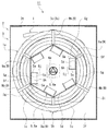
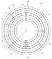
ここにおいて、段ボール箱体3は、例えば、矩形形状の六面体、すなわち直六面体からなる。そして、この段ボール箱体3には、通水管1をその端部から順に外に引き出すための引出部3cが備わっている。詳細には、引出部3cは、段ボール箱体3における、通水管1を引き出す際に上部に位置する上壁3tに設けられている。そして、引出部3cには、その引出部3cを開閉する蓋3dが設けられている。また、段ボール箱体3には、蓋3dの閉状態および開状態を保持するための保持手段Hとなるクリップ4が設けられている。なお、符号3pは、段ボール箱体3の各側壁3fに明けられた貫通孔であり、この貫通孔3pに、後に詳述する軸部材6が挿通される。そして、この貫通孔3pによって、回動部材5が回動する回動軸心Jが形成されるが、図示実施の形態においては、回動軸心Jは、段ボール箱体3の上方側に、偏心位置している。   Here, the cardboard box 3 is formed of, for example, a rectangular hexahedron, that is, a rectangular parallelepiped. The corrugated cardboard box 3 is provided with a drawing portion 3c for pulling out the water pipe 1 in order from its end. In detail, the drawer | drawing-out part 3c is provided in the upper wall 3t located in the upper part, when pulling out the water pipe 1 in the cardboard box body 3. FIG. The drawer 3c is provided with a lid 3d that opens and closes the drawer 3c. Further, the cardboard box body 3 is provided with a clip 4 serving as a holding means H for holding the lid 3d in a closed state and an open state. Reference numeral 3p denotes a through hole opened in each side wall 3f of the cardboard box body 3, and a shaft member 6 described in detail later is inserted into the through hole 3p. Then, the through hole 3p forms a rotation axis J around which the rotation member 5 rotates. In the illustrated embodiment, the rotation axis J is located above the cardboard box body 3, Eccentric position.

回動部材5は、例えば紙製(詳細には、段ボール製)であって、巻回束1aとともに、段ボール箱体3に収容されて、その巻回束1aを支えるものである。詳細には、回動部材5は、通水管1がその端部から順に段ボール箱体3の外に引き出されるよう、巻回束1aを支えてその巻回束1aとともにその巻回束1aの周方向に回動可能に支持される。   The rotating member 5 is made of, for example, paper (specifically, made of cardboard), and is housed in the cardboard box 3 together with the wound bundle 1a to support the wound bundle 1a. Specifically, the rotating member 5 supports the winding bundle 1a so that the water pipe 1 is drawn out of the cardboard box 3 in order from the end portion thereof, and the circumference of the winding bundle 1a together with the winding bundle 1a. It is supported so as to be rotatable in the direction.

この回動部材5は、本体部5aと一対の側板部5b、5bとを備えている。本体部5aは、両側に開口を有する中空筒体からなり、前記巻回束1aの内側空間部1c内に挿入されて、その巻回束1aが外周側に配置されるものである。一方、側板部5bは、本体部5aの外周側に配置された前記巻回束1aの側面1bが段ボール箱体3の内面(すなわち、段ボール箱体3の側壁3fの内面)と摺接するのを防止すべく、本体部5aの両側に取り付けられている。そして、この側板部5bに、軸孔5cが明けられ、この軸孔5cに、後に詳述する軸部材6が挿通される。また、側板部5b、5bの少なくとも一方(図示実施の形態においては両方)には、本体部5a内に起立する起立片5dが設けられ、本体部5aと側板部5b、5bとは、起立片5dの平板面からなる起し面が、本体部5aの内面に面接触するようにして接合されて、組み付けられている。さらに、側板部5bには、起立片5dの起立状態を維持すべく、起立片5dと交差する方向に起立し、その起立片5dを内側から支える支持片5eが設けられている。   The rotating member 5 includes a main body portion 5a and a pair of side plate portions 5b and 5b. The main body 5a is formed of a hollow cylinder having openings on both sides, and is inserted into the inner space 1c of the wound bundle 1a, and the wound bundle 1a is disposed on the outer peripheral side. On the other hand, in the side plate portion 5b, the side surface 1b of the wound bundle 1a disposed on the outer peripheral side of the main body portion 5a is in sliding contact with the inner surface of the cardboard box body 3 (that is, the inner surface of the side wall 3f of the cardboard box body 3). In order to prevent, it is attached to both sides of the main body 5a. A shaft hole 5c is opened in the side plate portion 5b, and a shaft member 6 described in detail later is inserted into the shaft hole 5c. Further, at least one of the side plate portions 5b and 5b (both in the illustrated embodiment) is provided with an upright piece 5d that stands up in the main body portion 5a, and the main body portion 5a and the side plate portions 5b and 5b are provided as upright pieces. A raised surface composed of a flat plate surface of 5d is joined and assembled so as to be in surface contact with the inner surface of the main body portion 5a. Further, the side plate portion 5b is provided with a support piece 5e that stands up in a direction crossing the upright piece 5d and supports the upright piece 5d from the inside in order to maintain the upright state of the upright piece 5d.

具体的には、本体部5aは、断面多角形状(図示実施の形態においては、断面正多角形状となる、断面正六角形状)に形成され、前記巻回束1aを支持すべく、その断面多角形状の各角部5fが巻回束1aの内周面1dに略当接するように設けられている。そして、起立片5dは、複数(図示実施の形態においては、各角部5fに対応した数、すなわち計6個)設けられている。これら起立片5d、5dは、本体部5aの各角部5f部分を内面側から支持するようにして、本体部5aの角部5fを構成する壁体5g、5gの少なくとも一方(図示実施の形態においては、一方)の壁体5gの内面と面接触する。そして、起立片5dと本体部5aとの間には、それら起立片5dと本体部5aとを固着すべく、接着材、両面粘着テープ、あるいは面ファスナー等の固着材(図示せず)が設けられている。もっとも、本体部5aと側板部5bとが接合されるのであれば、起立片5dと本体部5aとを、固着材によって固着しなくとも、ホッチキス等によって固定してもよく、また、単に押圧によって固定してもよい。   Specifically, the main body portion 5a is formed in a polygonal cross section (in the illustrated embodiment, a regular hexagonal cross section, which is a regular polygonal cross section), and has a polygonal cross section to support the wound bundle 1a. Each corner 5f of the shape is provided so as to substantially contact the inner peripheral surface 1d of the wound bundle 1a. Further, a plurality of upright pieces 5d (in the illustrated embodiment, the number corresponding to each corner 5f, that is, a total of six) is provided. These upright pieces 5d and 5d support at least one of the corners 5f of the main body 5a so as to support each corner 5f of the main body 5a from the inner surface side (the illustrated embodiment). In (1), it is in surface contact with the inner surface of the wall body 5g. And between the standing piece 5d and the main body 5a, a fixing material (not shown) such as an adhesive, a double-sided adhesive tape, or a hook-and-loop fastener is provided to fix the rising piece 5d and the main body 5a. It has been. But if the main-body part 5a and the side-plate part 5b are joined, the standing piece 5d and the main-body part 5a may be fixed by a stapler etc., even if it does not adhere with an adhering material, or only by pressing. It may be fixed.

また、側板部5bは、複数枚の段ボール板7、7が重ね合わされて、それら段ボール板7、7の接合により形成されている。そこで、前記起立片5dは、側板部5bの一部となる、複数枚の段ボール板7、7における相対的に内側の段ボール板7a(7)の一部が、切り起こされて形成され、支持片5eは、側板部5bの一部となる、複数枚の段ボール板7、7における相対的に外側の段ボール板7b(7)の一部が、切り起こされて形成されている。特に、起立片5dにあっては、側板部5bの一部となる、前記内側の段ボール板7aの一部が、本体部5aの内側からその本体部5aに向かって切り起こされて起立している。そして、これら起立片5dと支持片5eとは、切り起こされる前において重合して形成され、側板部5bには、起立片5dおよび支持片5eを同時に起立させるべく、外側から起立片5dおよび支持片5eを押圧するための、押圧用の孔5hが形成されている。すなわち、この押圧用の孔5hは、起立片5dを起立させるべく、外側からその起立片5dを押圧するための、起立片押圧用の孔と、支持片5eを起立させるべく、外側からその支持片5eを押圧するための、支持片押圧用の孔とを、兼ねた共通の孔となっている。   The side plate portion 5 b is formed by joining a plurality of corrugated cardboard plates 7, 7 and joining the corrugated cardboard plates 7, 7. Therefore, the upright piece 5d is formed by cutting and raising a part of a relatively inner corrugated board 7a (7) in the plurality of corrugated boards 7 and 7, which is a part of the side plate 5b. The piece 5e is formed by cutting and raising a part of a relatively outer corrugated board 7b (7) in the plurality of corrugated boards 7, 7 which is a part of the side plate 5b. In particular, in the standing piece 5d, a part of the inner corrugated board 7a, which becomes a part of the side plate part 5b, is cut and raised from the inner side of the main body part 5a toward the main body part 5a. Yes. The standing piece 5d and the support piece 5e are formed by being polymerized before being cut and raised, and the side plate portion 5b is provided with the standing piece 5d and the support piece from the outside so that the standing piece 5d and the support piece 5e can stand up simultaneously. A pressing hole 5h for pressing the piece 5e is formed. That is, the pressing hole 5h is provided with an upright piece pressing hole for pressing the upright piece 5d from the outside in order to erect the upright piece 5d and the support piece 5e from the outside to support the upright piece 5d. It is a common hole that also serves as a support piece pressing hole for pressing the piece 5e.

より詳細には、側板部5bは、2枚の段ボール板7、7の接合(例えば、接着)により形成されている。したがって、2枚の段ボール板7、7の一方に前記起立片5dが形成され、他方に前記支持片5eが形成される。そして、図示実施の形態においては、前記押圧用の孔5hは、起立片5dおよび支持片5eの切り起こしによる孔からなる。また、2枚の段ボール板7、7は、それぞれが、例えば略四角形状に形成されて、それら段ボール板7、7が、45゜ずれた位置で重ね合わされている。そして、これら段ボール板7、7の中芯の目の方向は、直交するように形成されている。そして、支持片5eは、起立片5dを支持することから、強度上、この支持片5dの中芯の目の方向は、起立片5dの起し面に対して略直交する方向となるのが望ましい。なお、側板部5bには、補強のために、中央部分に、板紙等からなる補強板5iが接着等により接合されている。そして、この補強板5iおよび段ボール板7、7を貫通するようにして、前述の軸孔5cが明けられている。   More specifically, the side plate portion 5b is formed by joining (for example, bonding) two corrugated board plates 7 and 7 together. Accordingly, the upright piece 5d is formed on one of the two corrugated board plates 7 and 7, and the support piece 5e is formed on the other. In the illustrated embodiment, the pressing hole 5h is a hole formed by cutting and raising the standing piece 5d and the support piece 5e. Each of the two cardboard plates 7 and 7 is formed in, for example, a substantially square shape, and the cardboard plates 7 and 7 are overlapped at a position shifted by 45 °. And the direction of the core of these corrugated board boards 7 and 7 is formed so as to be orthogonal. Since the support piece 5e supports the upright piece 5d, in terms of strength, the direction of the core of the support piece 5d is substantially perpendicular to the upright surface of the upright piece 5d. desirable. In addition, a reinforcing plate 5i made of paperboard or the like is joined to the side plate portion 5b by bonding or the like at the center portion for reinforcement. The shaft hole 5c described above is opened so as to penetrate the reinforcing plate 5i and the corrugated board plates 7 and 7.

また、支持片5eは、起立片5dを90度を越えて起立させるべく、起立片5dの切り起こしによる孔の大きさに対し、起立片5d側が若干食み出る大きさで形成されて、その孔を強制的に通過して起立するようになっている。つまり、支持片5eを形成する切込みの、起立片5d側に位置する切込み5mは、先端ほど広がるように傾斜して形成されている(図9、図10参照)。そして、支持片5eは、その起立状態が維持されるよう、内側の段ボール板7aに係合する。すなわち、起立片5dの切り起こしによる孔には、係合凹部5jが形成されており、支持片5eをその孔を通過させて起立させると、支持片5eは、係合凹部5jに係合し、その起立状態が確実に維持される。また、支持片5eは、1つの起立片5dに対して2つ設けられており、それら支持片5e、5eは、互いに離れるように切り起こされ、そして、切り起こされる前においては、それら支持片5e、5e間が、切欠き孔5kとなっている。   Further, the support piece 5e is formed to have a size that slightly protrudes from the upright piece 5d side with respect to the size of the hole formed by cutting and raising the upright piece 5d so that the upright piece 5d is raised more than 90 degrees. It is designed to stand up by forcibly passing through the hole. That is, the cut 5m located on the upright piece 5d side of the cut forming the support piece 5e is formed so as to be inclined toward the tip (see FIGS. 9 and 10). And the support piece 5e is engaged with the inner corrugated board 7a so that the standing state may be maintained. That is, the engagement recess 5j is formed in the hole formed by cutting and raising the upright piece 5d. When the support piece 5e is raised through the hole, the support piece 5e is engaged with the engagement recess 5j. The standing state is reliably maintained. Two support pieces 5e are provided for one upright piece 5d. The support pieces 5e and 5e are cut and raised so as to be separated from each other. A notch hole 5k is formed between 5e and 5e.

軸部材6は、回動部材5が巻回束1aとともにその巻回束1aの周方向に回動可能となるよう支持するものである。ここで、回動部材5が巻回束1aとともに回動するとは、回動部材5が巻回束1aと一体となって回動する場合は勿論、回動部材5が巻回束1aよりも遅れて回動する場合をも含むものである。この軸部材6は、例えば紙製であって、図3に示すように、段ボール箱体3における、前記巻回束1aの各側面1b、1bと対向する側壁3f、3fに、渡されるようにして取り付けられる。詳細には、軸部材6は、回動部材5に明けられた軸孔5c、5cに挿通されて、両側壁3f、3fに渡される。   The shaft member 6 supports the rotating member 5 so as to be rotatable in the circumferential direction of the wound bundle 1a together with the wound bundle 1a. Here, the rotation member 5 rotates together with the winding bundle 1a when the rotation member 5 rotates together with the winding bundle 1a as well as the rotation member 5 than the winding bundle 1a. This includes the case of rotating with a delay. The shaft member 6 is made of paper, for example, and is passed to the side walls 3f and 3f facing the side surfaces 1b and 1b of the wound bundle 1a in the cardboard box 3 as shown in FIG. Attached. Specifically, the shaft member 6 is inserted into the shaft holes 5c and 5c opened in the rotating member 5 and passed to the side walls 3f and 3f.

ここで、軸部材6は、少なくとも二つの分割体8、8によって形成される。そして、軸部材6は、段ボール箱体3の側壁3f、3fが外方に広がることを許容すべく、各分割体8、8が互いの軸心がずれることなくその軸方向に相対移動するようにして、前記軸方向に伸長可能となっている。詳細には、各分割体8、8は、巻回束1aの重量で、各分割体8、8がその軸方向に相対移動して前記側壁3f、3fが外方に広がることがなく、一方、通水管1を引き出すべく所要の力が作用したときに、各分割体8、8がその軸方向に相対移動して前記側壁3f、3fが外方に広がるように、所定の強度をもって組み付けられている。なお、軸部材6は、非伸長状態においては、前記側壁3f、3fが内方にへこむのを防止すべく、前記軸方向への縮みが不能となっている。   Here, the shaft member 6 is formed by at least two divided bodies 8 and 8. The shaft member 6 is configured so that the divided bodies 8 and 8 move relative to each other in the axial direction without misalignment with respect to each other in order to allow the side walls 3f and 3f of the cardboard box 3 to spread outward. Thus, it can be extended in the axial direction. Specifically, each of the divided bodies 8 and 8 is not affected by the weight of the wound bundle 1a so that the divided bodies 8 and 8 are relatively moved in the axial direction so that the side walls 3f and 3f are not spread outward. When a necessary force is applied to pull out the water pipe 1, the divided bodies 8 and 8 are assembled with a predetermined strength so that the side walls 3f and 3f spread outwardly with relative movement in the axial direction. ing. In addition, the shaft member 6 cannot be contracted in the axial direction in order to prevent the side walls 3f and 3f from being recessed inwardly in a non-expanded state.

より詳細には、軸部材6は、一対の前記分割体8、8によって構成されている。そして、一対の分割体8、8が、段ボール箱体3の各側壁3f、3fに固着され、それら各側壁3f、3fの、外方への広がりとともに離間するように組み付けられている。ここで、一対の分割体8、8は、それぞれが、前記各側壁3fに明けられた貫通孔3pおよび回動部材5に明けられた軸孔5cに挿通される軸本体6aと、その軸本体6aの端部に設けられて各側壁3fの外面と対向する鍔部6bとを有する。   More specifically, the shaft member 6 is constituted by a pair of the divided bodies 8 and 8. The pair of divided bodies 8 and 8 are fixed to the side walls 3f and 3f of the cardboard box 3, and are assembled so that the side walls 3f and 3f are separated from each other as they extend outward. Here, each of the pair of divided bodies 8, 8 includes a shaft main body 6 a inserted through the through hole 3 p opened in each side wall 3 f and the shaft hole 5 c opened in the rotating member 5, and the shaft main body It has a flange 6b provided at the end of 6a and facing the outer surface of each side wall 3f.

具体的には、図3および図11に示すように、軸本体6aは、例えば板紙が円筒状に形成された、管材からなる。一方、鍔部6bは、軸本体6の端面に接着等により固着された、例えば板紙によって形成された平板状の鍔材6cの、周縁部分からなる。そして、軸本体6aと鍔材6cとの固着を強固なものとするために、軸本体6aの内部には、その軸本体6aと鍔材6cとに渡るようにして、例えば板紙からなる補強材6dが設けられている。ここで、一方の分割体8a(8)には、その一方の分割体8a(8)と他方の分割体8b(8)とを接続するための、連接材6eが設けられている。そして、他方の分割体8b(8)は、連接材6eに対して、前記軸方向にスライド可能となっており、こうして、各分割体8a、8bは、互いの軸心がずれることなくその軸方向に相対移動する。 Specifically, as shown in FIGS. 3 and 11, the shaft body 6a is made of a tube material in which, for example, a paperboard is formed in a cylindrical shape. On the other hand, the flange portion 6b is fixedly attached by bonding or the like to the end face of the shaft body 6 a, for example, of a flat flange member 6c formed by cardboard, made from the peripheral portion. Then, in order to strengthen the fixation between the shaft main body 6a and the collar member 6c, a reinforcing material made of, for example, paperboard is provided inside the shaft main body 6a so as to extend over the shaft main body 6a and the collar member 6c. 6d is provided. Here, one divided body 8a (8) is provided with a connecting member 6e for connecting the one divided body 8a (8) and the other divided body 8b (8). The other divided body 8b (8) is slidable in the axial direction with respect to the connecting member 6e. Thus, each divided body 8a, 8b has its axis aligned without shifting its axis. Move relative to the direction.

図示実施の形態においては、連接材6eは、例えば、段ボールが折り曲げられて形成されており、一方の分割体8aの軸本体6aに挿入されて止められている。そして、他方の分割体8bは、その軸本体6aが、前記連接材6eに対して、前記軸方向にスライド可能に嵌合する。また、軸部材6が、非伸長状態にあるときに、両分割体8a、8bの軸本体6a、6aが突き合わされることとなり、こうして、この軸部材6は、非伸長状態からの縮みが不能となっている。なお、鍔部6bは、段ボール箱体3の側壁3fの外面に接着等により固定されており、こうして、分割体8は、前記側壁3fに固着される。   In the illustrated embodiment, the connecting member 6e is formed by bending a corrugated cardboard, for example, and is inserted into the shaft body 6a of one divided body 8a and stopped. The other divided body 8b is fitted so that the shaft body 6a can slide in the axial direction with respect to the connecting material 6e. Further, when the shaft member 6 is in the non-expanded state, the shaft bodies 6a and 6a of both the divided bodies 8a and 8b are abutted, and thus the shaft member 6 cannot be contracted from the non-expanded state. It has become. The flange portion 6b is fixed to the outer surface of the side wall 3f of the corrugated cardboard box 3 by adhesion or the like, and thus the divided body 8 is fixed to the side wall 3f.

また、巻回束1aにおける結束は、巻回束1aの外周側から内周側に向かって段階的に開放可能となっている。詳細には、巻回束1aは、その径方向において、複数の結束具によって多段的に結束されている。具体的には、結束具は、巻回束1aに巻き付けられる結束線類9からなる。そして、結束線類9は、例えば、帯状に形成されている。図示実施の形態においては、第1段階として、巻回束1aの内側部分が、結束線類9a(9)により結束され、そして、第2段階として、既に結束された部分の全体を含めてそれよりも外側部分まで結束線類9b(9)により結束されるというように、2段階に結束されている(図1ないし3参照)。もっとも、2段階に限定されるものではなく、多段階に結束されていれば、3段階、あるいは4段階以上であってもよい。さらに、第2段階以降は、巻回束1aにおける、既に結束された部分の一部を含めてそれよりも外側部分まで結束されてもよく、また、既に結束された部分とラップしないようにして、それよりも外側部分が結束されてもよい。   Further, the bundle in the wound bundle 1a can be opened stepwise from the outer peripheral side to the inner peripheral side of the wound bundle 1a. Specifically, the wound bundle 1a is bundled in a multistage manner by a plurality of binding tools in the radial direction. Specifically, the binding tool includes binding wires 9 wound around the winding bundle 1a. The binding wires 9 are formed in a band shape, for example. In the illustrated embodiment, as the first stage, the inner part of the wound bundle 1a is bound by the binding wires 9a (9), and as the second stage, the entire part already bound is included. It is bundled in two stages such that it is bundled to the outer part by the bundled wires 9b (9) (see FIGS. 1 to 3). However, it is not limited to two stages, and may be three stages or four or more stages as long as they are bundled in multiple stages. Further, after the second stage, the winding bundle 1a may be bundled up to the outer portion including a part of the already bundled portion, and should not be wrapped with the already bundled portion. The outer portion may be bound together.

そして、この梱包装置体11は、通水管1の引き出しに伴って、最終段階で開放される前記結束が開放されたときに、その開放によって広がった残りの巻回束1aが、段ボール箱体3の、巻回束1aの外周面と対向する周壁3iの内面に接触しないように、構成されている。すなわち、この梱包装置体11は、巻回束1aの結束における、最終段階で開放される量が所定以下であったり、あるいは、段ボール箱体3の大きさが所定以上であるように構成される。   Then, when the bundling body 1 is opened in the final stage as the water pipe 1 is pulled out, the remaining wound bundle 1a spread by the opening becomes the corrugated cardboard box 3 It is comprised so that it may not contact the inner surface of the surrounding wall 3i facing the outer peripheral surface of the winding bundle 1a. That is, the packing device body 11 is configured such that the amount released at the final stage in the binding of the wound bundle 1a is not more than a predetermined value, or the size of the cardboard box body 3 is not less than a predetermined value. .

次に、以上の構成からなる梱包装置体11の作用効果について説明する。この梱包装置体11によると、周回状に巻回された合成樹脂材料からなる通水管1の巻回束1aは、段ボール箱体3に収容されて、保管されたり運搬されたりする。そして、回動部材5は、巻回束1aを支えるようにして、その巻回束1aとともに、段ボール箱体3に収容される。軸部材6は、回動部材5が巻回束1aとともにその巻回束1aの周方向に回動可能となるよう支持するものであり、こうして、段ボール箱体3に収容された巻回束1aは、その巻回束1aの周方向に回動可能となる。ここで、結束線類9a、9bにより結束された巻回束1aの、その結束は、巻回束1aの外周側から内周側に向かって段階的に開放可能となっている。よって、通水管1を、巻回束1aの外周側の端部から順に外に引き出す際に、通水管1の引き出し量に応じて、順次、外側から巻回束1aの結束を開放することで(図示実施の形態においては、始めに、結束線類9b、9bを切断し(図4参照)、その後、結束線類9a、9aを切断することで)、巻回束1aのばらける量を減らすことができる。このことから、巻回束1aが段ボール箱体3の周壁3iに接触することがなく、あるいは、周壁3iへの巻回束1aの接触が和らげられる。そして、この通水管1の引き出しに伴って、巻回束1aとともに回動部材5が回動するが、このとき、巻回束1aが段ボール箱体3の周壁3iに接触することがなく、あるいは、周壁3iへの巻回束1aの接触が和らげられることから、通水管1の引き出しを円滑に行うことができる。そして、最終段階で開放される結束が開放されたときに、その開放によって広がった残りの巻回束1aが、段ボール箱体3の周壁3iの内面に接触しないことから、最終段階においても、通水管1の引き出しを円滑に行うことができる。   Next, the effect of the packaging apparatus body 11 which consists of the above structure is demonstrated. According to this packing apparatus body 11, the wound bundle 1a of the water flow pipe 1 made of a synthetic resin material wound in a circular shape is accommodated in the cardboard box 3 and stored or transported. And the rotation member 5 is accommodated in the cardboard box body 3 with the winding bundle 1a so that the winding bundle 1a may be supported. The shaft member 6 supports the rotating member 5 so as to be able to rotate in the circumferential direction of the wound bundle 1a together with the wound bundle 1a. Thus, the wound bundle 1a accommodated in the cardboard box body 3 is supported. Is rotatable in the circumferential direction of the wound bundle 1a. Here, the bundle of the wound bundle 1a bound by the binding wires 9a and 9b can be opened stepwise from the outer peripheral side to the inner peripheral side of the wound bundle 1a. Therefore, when pulling out the water pipe 1 in order from the outer peripheral side end of the wound bundle 1a, the bundle of the wound bundle 1a is sequentially opened from the outside according to the pulling amount of the water pipe 1. (In the illustrated embodiment, first, the binding wires 9b and 9b are cut (see FIG. 4), and then the binding wires 9a and 9a are cut). Can be reduced. For this reason, the wound bundle 1a does not contact the peripheral wall 3i of the cardboard box 3, or the contact of the wound bundle 1a with the peripheral wall 3i is eased. As the water pipe 1 is pulled out, the rotating member 5 rotates together with the wound bundle 1a. At this time, the wound bundle 1a does not contact the peripheral wall 3i of the cardboard box 3, or Since the contact of the wound bundle 1a with the peripheral wall 3i is eased, the water pipe 1 can be pulled out smoothly. When the bundle released in the final stage is released, the remaining wound bundle 1a spread by the opening does not come into contact with the inner surface of the peripheral wall 3i of the cardboard box body 3. The water tube 1 can be pulled out smoothly.

しかも、巻回束1aのばらける量を減らすことができることから、巻回束1aから離れようとする部分の通水管1が巻回束1aの内部に食い込み難くなり、回動部材5とか軸部材6とか段ボール箱体3にかかる負荷が小さくなり、このことによっても、通水管1の引き出しを円滑に行うことができる。   In addition, since the amount of the winding bundle 1a that can be separated can be reduced, it becomes difficult for the water pipe 1 in the portion that is about to be separated from the winding bundle 1a to bite into the inside of the winding bundle 1a. 6 and the load applied to the corrugated cardboard box 3 are reduced, and the water pipe 1 can be pulled out smoothly by this.

さらに、巻回束1aのばらける量を減らすことで、その巻回束1aが回動部材5の下方に垂れ下がる寸法を小さくすることができる。よって、この巻回束1aの重心が、回動部材5の回動軸心Jからずれる値が小さくなり、こうして、この巻回束1aが回動するのに伴ってその回動が変則的となるのを抑えることができる。したがって、これによっても、通水管1の引き出しを円滑に行うことができる。   Furthermore, the dimension by which the winding bundle 1a hangs down below the rotating member 5 can be reduced by reducing the amount of the winding bundle 1a that is scattered. Therefore, the value of the center of gravity of the wound bundle 1a deviating from the rotational axis J of the rotating member 5 becomes small, and thus the rotation is irregular as the wound bundle 1a rotates. Can be suppressed. Therefore, the water pipe 1 can be pulled out smoothly also by this.

その上、巻回束1aの内側部分の結束が開放されるまでは、巻回束1aの内径が維持されて、回動部材5が巻回束1aとともに円滑に回動することが可能となることから、通水管1が回動部材5と擦って傷付くのを防ぐことができるとともに、通水管1の引き出しを円滑にすることができる。なお、巻回束1aは、回動部材5の構成如何によっては、回動部材5とともに結束され得る。そして、このように、巻回束1aが回動部材5とともに結束されることで、回動部材5は、巻回束1aと一体となって、一層円滑に回動することができる。   In addition, the inner diameter of the wound bundle 1a is maintained until the binding of the inner part of the wound bundle 1a is released, and the rotating member 5 can smoothly rotate together with the wound bundle 1a. As a result, the water pipe 1 can be prevented from being rubbed against the rotating member 5 and damaged, and the water pipe 1 can be pulled out smoothly. The winding bundle 1 a can be bundled together with the rotating member 5 depending on the configuration of the rotating member 5. In this way, the winding bundle 1a is bundled together with the rotating member 5, so that the rotating member 5 is integrated with the winding bundle 1a and can be rotated more smoothly.

また、回動部材5は、巻回束1aが外周側に配置される本体部5aと、巻回束1aが段ボール箱体3の内面、すなわち側壁3f、3fの内面と摺接するのを防止する一対の側板部5b、5bとを備えている。そして、本体部5aは、両側に開口を有する中空筒体からなり、側板部5b、5bは、本体部5aの両側に取り付けられる。ここにおいて、側板部5b、5bの少なくとも一方に設けられた起立片5dの起し面が、本体部5aの内面に面接触するようにして接合されており、この面接触により、本体部5aと側板部5bとの一体性が保たれる。したがって、このような簡単な構造で、この回動部材5の強度を確保することができる。しかも、本体部5aにおいて、その断面多角形状の各角部5fが、巻回束1aの内周面1dに略当接し、起立片5dが、本体部5aの前記各角部5f部分を内面側から支持することで、この回動部材5の強度は、十分に確保される。そして、通水管1を、配管する場合には、段ボール箱体3内の通水管1を、その端部から順に、段ボール箱体3に備わる引出部3cを通して、段ボール箱体3の外に引き出すが、この引き出しに伴って、段ボール箱体3内の巻回束1aが解かれるようにして、回動部材5とともにその巻回束1aが回動する。   Further, the rotating member 5 prevents the main body 5a in which the wound bundle 1a is disposed on the outer peripheral side and the wound bundle 1a from being in sliding contact with the inner surface of the cardboard box 3, that is, the inner surfaces of the side walls 3f and 3f. A pair of side plate portions 5b and 5b is provided. And the main-body part 5a consists of a hollow cylinder which has an opening in both sides, and the side-plate parts 5b and 5b are attached to the both sides of the main-body part 5a. Here, the rising surface of the standing piece 5d provided on at least one of the side plate portions 5b and 5b is joined so as to be in surface contact with the inner surface of the main body portion 5a. The integrity with the side plate portion 5b is maintained. Therefore, the strength of the rotating member 5 can be ensured with such a simple structure. Moreover, in the main body portion 5a, each corner portion 5f having a polygonal cross section substantially abuts on the inner peripheral surface 1d of the wound bundle 1a, and the upright piece 5d connects each corner portion 5f portion of the main body portion 5a to the inner surface side. By supporting from the above, the strength of the rotating member 5 is sufficiently secured. When the water pipe 1 is piped, the water pipe 1 in the cardboard box body 3 is drawn out of the cardboard box body 3 from the end portion through the lead-out part 3c provided in the cardboard box body 3. With this drawing, the wound bundle 1a is rotated together with the rotating member 5 so that the wound bundle 1a in the cardboard box 3 is unwound.

また、回動部材5における側板部5bに、起立片5dを内側から支える支持片5eが設けられており、この支持片5eにより、起立片5dの起立状態が確実に維持される。ここにおいて、図10に示すように、本体部5aと側板部5bとを組み合わせた状態で、例えば押圧治具15を用いることで、側板部5bの外側から、押圧用の孔5hを通して、起立片5dおよび支持片5eを押圧して、それら起立片5dおよび支持片5eを切り起こして起立させる。こうして、起立片5dの起し面を、本体部5aの内面に面接触させるとともに、支持片5eによって起立片5dを支えて、本体部5aと側板部5bとを組み付けることができる。したがって、本体部5aと側板部5bに巻回束1aを組み合わせた状態で、側板部5bの外側から、押圧用の孔5hを通して、起立片5dおよび支持片5eを切り起こして起立させることで、この回動部材5に巻回束1aが簡単に取り付けられる。なお、図10に示される、押圧治具15は、治具本体15aと、その治具本体15aの先端付近から突出する補助板15b、15bとからなる。そして、治具本体15aの先端部分が、切欠き孔5kから進入して起立片5dを押圧し、補助板15b、15bが、支持片5e、5eを押圧するようになっている。   Further, the side plate portion 5b of the rotating member 5 is provided with a support piece 5e that supports the upright piece 5d from the inside, and the upright state of the upright piece 5d is reliably maintained by the support piece 5e. Here, as shown in FIG. 10, in the state where the main body portion 5a and the side plate portion 5b are combined, for example, a pressing jig 15 is used, so that the standing piece is passed from the outside of the side plate portion 5b through the pressing hole 5h. 5d and the support piece 5e are pressed, and the standing piece 5d and the support piece 5e are cut and raised to stand. In this manner, the rising surface of the standing piece 5d can be brought into surface contact with the inner surface of the main body portion 5a, and the standing piece 5d can be supported by the support piece 5e to assemble the main body portion 5a and the side plate portion 5b. Therefore, in the state in which the wound bundle 1a is combined with the main body portion 5a and the side plate portion 5b, the standing piece 5d and the support piece 5e are cut and raised from the outside of the side plate portion 5b through the pressing hole 5h. The winding bundle 1a is easily attached to the rotating member 5. The pressing jig 15 shown in FIG. 10 includes a jig main body 15a and auxiliary plates 15b and 15b protruding from the vicinity of the tip of the jig main body 15a. And the front-end | tip part of the jig | tool main body 15a approachs from the notch hole 5k, presses the standing piece 5d, and the auxiliary plates 15b and 15b press the support pieces 5e and 5e.

そして、起立片5dとか支持片5eは、切り起こしによって形成されることで、この起立片5dおよび支持片5eは、簡単に形成される。しかも、これら起立片5dと支持片5eとが、異なる段ボール板7a、7bの切り起こしによって形成されることで、これら起立片5dおよび支持片5eは、所定の位置に簡単に形成される。   And the standing piece 5d and the support piece 5e are formed by cutting and raising, so that the standing piece 5d and the support piece 5e are easily formed. Moreover, the upright pieces 5d and the support pieces 5e are formed by cutting and raising the different corrugated cardboard plates 7a and 7b, so that the upright pieces 5d and the support pieces 5e are easily formed at predetermined positions.

さらに、起立片5dにあっては、90度を越えて起立することから、その起立片5dの起し面が、本体部5aの内面を押圧し、この起立片5dは、本体部5aに確実に接合される。そして、支持片5eは、起立片5dの切り起こしによる孔を強制的に通過して起立することから、この支持片5eの戻りが阻止される。   Further, since the standing piece 5d rises over 90 degrees, the rising surface of the standing piece 5d presses the inner surface of the main body portion 5a, and this rising piece 5d is securely attached to the main body portion 5a. To be joined. Since the support piece 5e stands up by forcibly passing through the hole formed by cutting and raising the upright piece 5d, the return of the support piece 5e is prevented.

また、予め、本体部5aの内面と起立片5dの起し面との少なくとも一方に固着材を設けておき、本体部5aと側板部5bとを組み合わせた状態で、側板部5bの外側から、押圧用の孔5hを通して、起立片5dを押圧して、その起立片5dを切り起こして起立させることで、起立片5dの起し面を、本体部5aの内面に面接触させれば、これと同時に、起立片5dと本体部5aとを固着することができる。もちろん、起立片5dの起し面の全面が本体部5aに固着される必要はなく、起し面の一部が本体部5aに固着されても構わない。   Further, in advance, a fixing material is provided on at least one of the inner surface of the main body portion 5a and the rising surface of the upright piece 5d, and in a state where the main body portion 5a and the side plate portion 5b are combined, from the outside of the side plate portion 5b, If the upright piece 5d is pressed through the pressing hole 5h, and the upright piece 5d is cut up and raised to bring the upright surface of the upright piece 5d into surface contact with the inner surface of the main body 5a, At the same time, the standing piece 5d and the main body 5a can be fixed. Of course, the entire raising surface of the upright piece 5d need not be fixed to the main body 5a, and a part of the rising surface may be fixed to the main body 5a.

軸部材6は、段ボール箱体3における、巻回束1aの各側面1b、1bと対向する側壁3f、3fに、渡されるようにして取り付けられる。この軸部材6は、回動部材5が巻回束1aとともにその巻回束1aの周方向に回動可能となるように支持するものであり、こうして、段ボール箱体3に収容された巻回束1aは、その巻回束1aの周方向に回動可能となる。   The shaft member 6 is attached so as to be passed to the side walls 3f and 3f facing the side surfaces 1b and 1b of the wound bundle 1a in the cardboard box body 3. The shaft member 6 supports the rotating member 5 so as to be able to rotate in the circumferential direction of the winding bundle 1a together with the winding bundle 1a. Thus, the winding housed in the cardboard box body 3 is supported. The bundle 1a can be rotated in the circumferential direction of the wound bundle 1a.

ここで、軸部材6は、各分割体8a、8bが互いの軸心がすれることなくその軸方向に相対移動するようにして、軸方向に伸長可能となっており、こうして、段ボール箱体3の側壁3f、3fが外方に広がるのが許容される。これにより、通水管1を引き出す力が、段ボール箱体3に作用すると、軸部材6がその軸方向に伸長することで、段ボール箱体3の側壁3f、3fは、外方に広がる。したがって、通水管1の引き出しによって、回動部材5が軸部材6とのクリアランス等により傾いても、その回動部材5は、前記側壁3fの内面に接触しないか、あるいは、前記側壁3fの内面への押圧力が軽減され、こうして、この回動部材5を円滑に回動させることができる。しかも、各分割体8a、8bは、巻回束1aの重量で各分割体8a、8bがその軸方向に相対移動して段ボール箱体3の側壁3f、3fが外方に広がることがなく、そして、通水管1を引き出すべく所要の力が作用したときに、各分割体8a、8bがその軸方向に相対移動して前記側壁3f、3fが外方に広がるように、所定の強度をもって組み付けられているので、前記側壁3f、3fが、安易に外方に広がることがなく、この段ボール箱体3の不必要な変形が抑えられる。   Here, the shaft member 6 can be extended in the axial direction such that the respective divided bodies 8a and 8b move relative to each other without being centered on each other, and thus the corrugated cardboard box. 3 side walls 3f and 3f are allowed to spread outward. Thereby, when the force which pulls out the water flow pipe 1 acts on the corrugated cardboard box 3, the shaft member 6 extends in the axial direction, so that the side walls 3f and 3f of the corrugated cardboard box 3 spread outward. Therefore, even if the rotating member 5 is inclined due to the clearance with the shaft member 6 or the like by pulling out the water conduit 1, the rotating member 5 does not contact the inner surface of the side wall 3f or the inner surface of the side wall 3f. Thus, the rotation member 5 can be smoothly rotated. Moreover, each of the divided bodies 8a and 8b does not cause the divided bodies 8a and 8b to move relative to each other in the axial direction due to the weight of the wound bundle 1a so that the side walls 3f and 3f of the cardboard box body 3 are spread outward. Then, when a necessary force is applied to pull out the water pipe 1, the divided bodies 8a and 8b are relatively moved in the axial direction so that the side walls 3f and 3f spread outward, and are assembled with a predetermined strength. Therefore, the side walls 3f and 3f do not easily spread outward, and unnecessary deformation of the cardboard box 3 can be suppressed.

また、この軸部材6において、一対の分割体8a、8bが、各側壁3f、3fに固着されて取り付けられることで、通水管1を引き出す力とか、通水管1の自重等が、分割体8a、8bから側壁3f、3fに安定して伝わる。したがって、側壁3f、3fにおける、分割体8a、8bが取り付けられる部分の変形が抑えられる。   Further, in this shaft member 6, the pair of divided bodies 8 a and 8 b are fixedly attached to the side walls 3 f and 3 f so that the force for pulling out the water pipe 1, the own weight of the water pipe 1, etc. , 8b are stably transmitted to the side walls 3f and 3f. Therefore, the deformation of the portions to which the divided bodies 8a and 8b are attached on the side walls 3f and 3f is suppressed.

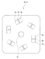
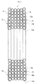
なお、本発明は、上述した実施の形態に限定されるわけではなく、その他種々の変更が可能である。例えば、結束具は、結束線類9からならなくとも、図12および図13に示すように、巻回束1aの各側面1bに取り付けられて、その巻回束1aの径方向に並ぶ通水管1を保持する、保持部材10からなってもよい。この保持部材10は、例えば合成樹脂材料からなり、少なくとも巻回束1aの径方向の各側で、通水管1に嵌められるクリップ部10a、10aと、それらクリップ部10a、10aを連結する連結部10bとを有している。そして、複数の保持部材10、10は、その全てが、同一形状かつ同一サイズとなっている。ここで、クリップ部10aは、通水管1を保持するように、通水管の周面を180度を越えて覆うように、かつ、先端部分が開口して形成されている。そして、連結部10bは、各クリップ部10a、10aを連結するように、例えば帯状に形成されている。この保持部材10によると、クリップ部10aが通水管1に嵌められて、保持部材10は、巻回束1aの各側面1bに取り付けられる。そして、この取り付けられた保持部材10によって、巻回束1aは、結束される。このとき、一種類の保持部材10を、共通に用いることで、保持部材10の部品コストを下げることができ、また、巻回束1aへの保持部材10の取付作業を簡単に行うことができる。なお、図示実施の形態においては、クリップ部10aは、連結部10bの各端に設けられているが、それらに加えて、連結部10bの中間部分に設けられてもよい。さらに、クリップ部10aは、連結部10bの一方の端と、中間部分に設けられてもよく、また、連結部10bの中間部分のみに複数設けられてもよい。また、このように、保持部材10は、クリップ部10aを有しているが、このクリップ部10aに替えて、通水管1に掛けられるフック部を有してもよい。   In addition, this invention is not necessarily limited to embodiment mentioned above, A various other change is possible. For example, as shown in FIG. 12 and FIG. 13, the bundling tool is attached to each side surface 1b of the wound bundle 1a and arranged in the radial direction of the wound bundle 1a, even if the binding tool is not made of the binding wires 9 1 may be comprised of a holding member 10. The holding member 10 is made of, for example, a synthetic resin material, and at least on each side in the radial direction of the wound bundle 1a, clip portions 10a and 10a that are fitted to the water pipe 1 and a connecting portion that connects the clip portions 10a and 10a. 10b. All of the plurality of holding members 10 and 10 have the same shape and the same size. Here, the clip portion 10a is formed so as to cover the circumferential surface of the water flow tube over 180 degrees so as to hold the water flow tube 1 and the tip portion is opened. And the connection part 10b is formed in strip | belt shape, for example so that each clip part 10a, 10a may be connected. According to this holding member 10, the clip part 10a is fitted to the water flow pipe 1, and the holding member 10 is attached to each side surface 1b of the wound bundle 1a. The wound bundle 1a is bound by the attached holding member 10. At this time, by using one type of holding member 10 in common, the component cost of the holding member 10 can be reduced, and the attaching operation of the holding member 10 to the wound bundle 1a can be easily performed. . In the illustrated embodiment, the clip portion 10a is provided at each end of the connecting portion 10b. However, in addition to these, the clip portion 10a may be provided at an intermediate portion of the connecting portion 10b. Furthermore, the clip part 10a may be provided at one end of the connecting part 10b and an intermediate part, or a plurality of clip parts 10a may be provided only at the intermediate part of the connecting part 10b. As described above, the holding member 10 includes the clip portion 10a. However, the holding member 10 may include a hook portion that is hung on the water conduit 1 instead of the clip portion 10a.

また、回動部材5において、側板部5bは、2枚の段ボール板7a、7bからならなくとも、3枚以上の段ボール板からなり、例えば、起立片5dが切り起こされた内側の段ボール板7aよりもさらに内側に他の段ボール板を有してもよい。また、この際、起立片5dおよび/または支持片5eは、その起立状態が維持されるよう、前記他の段ボール板に係合してもよい。そして、このように、起立片5dおよび/または支持片5eが、他の段ボール板に係合することで、起立片5dおよび/または支持片5eは、その起立状態が確実に維持される。もちろん、外側の段ボール板7bよりもさらに外側に、他の段ボール板が配備されても構わない。   Further, in the rotating member 5, the side plate portion 5b does not include the two corrugated cardboard plates 7a and 7b, but includes three or more corrugated cardboard plates. For example, the inner corrugated cardboard plate 7a from which the standing piece 5d is cut and raised. Furthermore, you may have another corrugated cardboard inside. At this time, the standing piece 5d and / or the support piece 5e may be engaged with the other corrugated board so that the standing state is maintained. In this way, the standing piece 5d and / or the support piece 5e are engaged with another corrugated board, so that the standing piece 5d and / or the support piece 5e are reliably maintained in the standing state. Of course, another corrugated board may be arranged further outside the outer corrugated board 7b.

また、起立片5dは、側板部5b(詳細には段ボール板7a)の一部が切り起こされて形成されているが、切り起こされることなく、別部材によって形成されてもよい。同様にして、支持片5eは、側板部5b(詳細には段ボール板7b)の一部が切り起こされて形成されているが、切り起こされることなく、別部材によって形成されてもよい。   Further, the standing piece 5d is formed by cutting and raising a part of the side plate portion 5b (specifically, the corrugated board 7a), but may be formed by another member without being cut and raised. Similarly, the support piece 5e is formed by cutting and raising a part of the side plate portion 5b (specifically, the corrugated board 7b), but may be formed by another member without being cut and raised.

また、回動部材5の本体部5aは、断面円形形状であっても構わなく、この場合、起立片5dの起し面は、湾曲面によって形成されていてもよい。また、起立片5dの起し面は、その全面が、本体部5aの内面に面接触するのが望ましいが、その一部が面接触するものであってもよい。   The main body 5a of the rotating member 5 may have a circular cross section. In this case, the rising surface of the upright piece 5d may be formed by a curved surface. Further, it is desirable that the rising surface of the standing piece 5d is in surface contact with the inner surface of the main body portion 5a, but a part thereof may be in surface contact.

また、軸部材6が軸方向に伸長することで、段ボール箱体3の側壁3f、3fが外方に広がるのは、通水管1を引き出す力が、段ボール箱体3に作用した場合に限らず、通水管1の自重等が、段ボール箱体3に作用した場合であってもよい。   Further, the side walls 3f and 3f of the corrugated cardboard box 3 are spread outward by the shaft member 6 extending in the axial direction, not only when the force for pulling out the water pipe 1 is applied to the corrugated cardboard box 3. The case where the weight of the water conduit 1 acts on the cardboard box 3 may be used.

また、段ボール箱体3における引出部3cは、その段ボール箱体3の一面を形成する壁の一部に設けられてもよいが、一面全体が、引出部3cとなっていてもよい。すなわち、段ボール箱体3の一面を形成する壁の一部が、引出部3cを開閉する蓋3dとなる場合の他に、その一面を形成する壁全体が、引出部3cを開閉する蓋3dとなっていてもよい。また、このように、引出部3cには、その引出部3cを開閉する蓋3dが設けられているが、この蓋3dは無くともよい。すなわち、引出部3cは、段ボール箱体3の壁部の適宜部分を除去することにより形成されてもよい。   Moreover, although the drawer | drawing-out part 3c in the cardboard box body 3 may be provided in a part of wall which forms one surface of the cardboard box body 3, the whole surface may become the drawer | drawing-out part 3c. That is, in addition to the case where a part of the wall forming one surface of the cardboard box 3 becomes the lid 3d for opening and closing the drawer portion 3c, the entire wall forming the one surface is the lid 3d for opening and closing the drawer portion 3c. It may be. As described above, the drawer 3c is provided with the lid 3d for opening and closing the drawer 3c. However, the lid 3d may not be provided. That is, the drawer portion 3 c may be formed by removing an appropriate portion of the wall portion of the cardboard box body 3.

また、この梱包装置2あるいは梱包装置体11は、通水管1を引き出すにあたって、縦置きにして(段ボール箱体3の側壁3fが縦になった状態で)用いてもよいが、横置きにして(段ボール箱体3の側壁3fが横になった状態で)用いても勿論よい。   Further, the packing device 2 or the packing device body 11 may be used in a vertical position (with the side wall 3f of the cardboard box 3 being vertical) when the water pipe 1 is pulled out. Of course, it may be used (with the side wall 3f of the cardboard box 3 lying down).

ところで、段ボール箱体3に収容される巻回束は、通水管1の巻回束1aでなくとも、通水管1以外の配管材の巻回束であってもよく、さらには、配管材の巻回束でなくとも、配線材(ケーブル)の巻回束であってもよい。   By the way, the wound bundle accommodated in the corrugated cardboard box 3 may not be the wound bundle 1a of the water pipe 1, but may be a wound bundle of piping materials other than the water pipe 1, and further, A winding bundle of wiring material (cable) may be used instead of the winding bundle.

この発明の一実施の形態の、梱包装置体の蓋を閉状態としたときの斜視図である。It is a perspective view when the lid | cover of the packing apparatus body is made into a closed state of one Embodiment of this invention. 同じく、図1におけるA−A線による断面図である。Similarly, it is sectional drawing by the AA in FIG. 同じく、図1におけるB−B線による断面図である。Similarly, it is sectional drawing by the BB line in FIG. 同じく、蓋を開状態とし、通水管を引き出すときの斜視図である。Similarly, it is a perspective view when the lid is opened and the water pipe is pulled out. 同じく、回動部材の斜視図である。Similarly, it is a perspective view of a rotation member. 同じく、回動部材の分解斜視図である。Similarly, it is a disassembled perspective view of a rotation member. 同じく、回動部材の側板部における、内側の段ボール板の展開図である。Similarly, it is a development view of the inner corrugated board in the side plate portion of the rotating member. 同じく、回動部材の側板部における、外側の段ボール板の展開図である。Similarly, it is an expanded view of the outer corrugated board board in the side board part of a rotation member. 同じく、回動部材の側板部の展開図である。Similarly, it is an expanded view of the side-plate part of a rotation member. 同じく、回動部材における、本体部と側板部との組付過程を示す斜視図である。Similarly, it is a perspective view which shows the assembly | attachment process of a main-body part and a side-plate part in a rotation member. 同じく、軸部材の分解斜視図である。Similarly, it is an exploded perspective view of a shaft member. この発明の他の実施の形態の、巻回束の正面図である。It is a front view of the winding bundle | flux of other embodiment of this invention. 同じく、図12におけるC−C線による断面図である。Similarly, it is sectional drawing by CC line in FIG. 従来の梱包装置を示す断面図である。It is sectional drawing which shows the conventional packing apparatus.

符号の説明Explanation of symbols

1 通水管(配線・配管材)
1a 巻回束
1b 側面
2 梱包装置
3 段ボール箱体
3c 引出部
3f 側壁
3p 貫通孔
5 回動部材
5b 側板部
5c 軸孔
6 軸部材
6a 軸本体
6b 鍔部
6e 連接材
8 分割体
1 Water pipe (wiring and piping materials)
DESCRIPTION OF SYMBOLS 1a Winding bundle 1b Side surface 2 Packing apparatus 3 Corrugated cardboard box 3c Drawer part 3f Side wall 3p Through-hole 5 Rotating member 5b Side plate part 5c Shaft hole 6 Shaft member 6a Shaft main body 6b collar part
6e Connecting material 8 Divided body

Claims (6)

周回状に巻回された配線・配管材の巻回束を梱包する梱包装置であって、
前記巻回束を収容するとともに、前記配線・配管材をその端部から順に外に引き出すための引出部が備わる、段ボール箱体と、
前記段ボール箱体に収容されて、前記巻回束を支える回動部材と、
前記段ボール箱体における、前記巻回束の各側面と対向する側壁に、渡されるようにして取り付けられて、前記回動部材が前記巻回束とともにその巻回束の周方向に回動可能となるよう支持する軸部材と、を備え、
前記軸部材は、少なくとも二つの分割体によって形成され、かつ、前記段ボール箱体の前記各側壁には、前記分割体がそれぞれ固着され、
前記軸部材は、前記各分割体が互いの軸心がずれることなくその軸方向に相対移動するようにして、前記軸方向に伸長可能となっており、前記軸部材が前記軸方向に伸長することで、前記段ボール箱体の前記側壁が外方に広がることを特徴とする、配線・配管材の梱包装置。
A packing device for packing a wound bundle of wiring / piping material wound in a circular shape,
A cardboard box body that accommodates the wound bundle and includes a lead-out portion for pulling out the wiring / piping material in order from its end portion;
A rotating member housed in the cardboard box body and supporting the wound bundle;
In the cardboard box body, attached to the side wall facing each side surface of the wound bundle so as to be passed, the rotating member can be rotated in the circumferential direction of the wound bundle together with the wound bundle. A shaft member that supports the
The shaft member is formed by at least two divided bodies, and the divided bodies are respectively fixed to the side walls of the cardboard box body,
The shaft member is pre SL each divided bodies so as to relatively move in the axial direction without mutual axis is shifted, has a extendable in the axial direction, extending the shaft member in the axial direction By doing so, the said side wall of the said cardboard box body spreads outward , The wiring and piping material packing apparatus characterized by the above-mentioned .
前記各分割体は、前記巻回束の重量で前記各分割体がその軸方向に相対移動して前記側壁が外方に広がることがなく、一方、前記配線・配管材を引き出すべく所要の力が作用したときに、前記各分割体がその軸方向に相対移動して前記側壁が外方に広がるように、所定の強度をもって組み付けられていることを特徴とする請求項1に記載の、配線・配管材の梱包装置。   Each of the divided bodies does not move relative to each other in the axial direction due to the weight of the wound bundle, and the side wall does not spread outward. On the other hand, a required force for pulling out the wiring / piping material is required. 2. The wiring according to claim 1, wherein each of the divided bodies is assembled with a predetermined strength so that the side walls spread outwardly when the divided bodies move relative to each other in the axial direction.・ Packing material packing equipment. 前記軸部材は、非伸長状態においては、前記側壁が内方にへこむのを防止すべく、前記軸方向への縮みが不能となっていることを特徴とする請求項1または2に記載の、配線・配管材の梱包装置。   3. The shaft member according to claim 1, wherein the shaft member is not allowed to shrink in the axial direction in order to prevent the side wall from being recessed inwardly in a non-elongated state. Wiring and piping material packing equipment. 前記軸部材は、一対の前記分割体によって形成され、
一方の前記分割体には、その一方の分割体と他方の前記分割体とを接続するための、連接材が設けられ、
前記他方の分割体は、前記連接材に対して、前記軸方向にスライド可能となっており、
これら一対の分割体が、前記各側壁の、外方への広がりとともに離間するように組み付けられていることを特徴とする請求項1ないし3のいずれか1項に記載の、配線・配管材の梱包装置。
The shaft member is formed by the division of a pair,
One of the divided bodies is provided with a connecting material for connecting the one divided body and the other divided body,
The other divided body is slidable in the axial direction with respect to the connecting material,
The pair of split bodies, the each side wall, according to any one of claims 1 to 3, characterized in that is assembled so as to separate with spreading outward, the wiring and piping material Packing equipment.
前記軸部材は、前記各側壁に明けられた貫通孔および前記回動部材に明けられた軸孔に挿通される軸本体と、その軸本体の端部に設けられて前記各側壁の外面と対向する鍔部とを有する、一対の前記分割体によって構成されていることを特徴とする請求項1ないし4のいずれか1項に記載の、配線・配管材の梱包装置。   The shaft member includes a through hole formed in each side wall and a shaft main body inserted into the shaft hole formed in the rotating member, and is provided at an end portion of the shaft main body so as to face the outer surface of each side wall. 5. The wiring / pipe material packing apparatus according to claim 1, wherein the wiring / pipe material packing device is configured by a pair of the divided bodies. 前記回動部材は、前記巻回束の側面が前記段ボール箱体の前記側壁の内面と摺接するのを防止する側板部を備えていることを特徴とする請求項1ないし5のいずれか1項に記載の、配線・配管材の梱包装置。   The said rotation member is provided with the side-plate part which prevents that the side surface of the said winding bundle | flux contacts the inner surface of the said side wall of the said corrugated-cardboard box body. Wiring / pipe material packaging equipment described in 1.
JP2003288148A 2003-08-06 2003-08-06 Wiring and piping material packing equipment Expired - Fee Related JP4177732B2 (en)

Priority Applications (1)

Application Number Priority Date Filing Date Title
JP2003288148A JP4177732B2 (en) 2003-08-06 2003-08-06 Wiring and piping material packing equipment

Applications Claiming Priority (1)

Application Number Priority Date Filing Date Title
JP2003288148A JP4177732B2 (en) 2003-08-06 2003-08-06 Wiring and piping material packing equipment

Publications (2)

Publication Number Publication Date
JP2005053678A JP2005053678A (en) 2005-03-03
JP4177732B2 true JP4177732B2 (en) 2008-11-05

Family

ID=34366918

Family Applications (1)

Application Number Title Priority Date Filing Date
JP2003288148A Expired - Fee Related JP4177732B2 (en) 2003-08-06 2003-08-06 Wiring and piping material packing equipment

Country Status (1)

Country Link
JP (1) JP4177732B2 (en)

Families Citing this family (4)

* Cited by examiner, † Cited by third party
Publication number Priority date Publication date Assignee Title
JP4668876B2 (en) * 2006-09-21 2011-04-13 未来工業株式会社 Packing body of water pipe
JP5109375B2 (en) * 2007-01-22 2012-12-26 三菱電機ビルテクノサービス株式会社 Repair device for moving handrail for passenger conveyor and repair method thereof
JP5227760B2 (en) * 2008-11-28 2013-07-03 株式会社タカギ Hose reel with springboard
DE202011052330U1 (en) * 2011-12-16 2013-03-19 Uponor Innovation Ab Unwinding device for a pipe collar and pipe collar

Also Published As

Publication number Publication date
JP2005053678A (en) 2005-03-03

Similar Documents

Publication Publication Date Title
US20140326625A1 (en) Packaging for Wound Coil
JP4177732B2 (en) Wiring and piping material packing equipment
JP4202860B2 (en) Rotating member for wiring and piping materials
JP4531363B2 (en) Piping material packing equipment
GB2165214A (en) Folded sheet reel hub
JP2004131181A (en) Transferring and supplying box with cut pieces of thick paper or cardboard and with strip member stored and wound into winding body
SE502768C2 (en) Metal-free disposable drum for an elongated flexible object
JP2010006421A (en) Small article organizing box
JP2010070233A (en) Protective frame for roll product
JP4231704B2 (en) Water pipe rotating device, water pipe packing device, and water pipe packing device body
JP4231703B2 (en) Water pipe rotating device, water pipe packing device, and water pipe packing device body
WO2016181485A1 (en) Package
JP4017530B2 (en) Water pipe packing equipment
JP4024159B2 (en) Water pipe packing device and water pipe packing device body
KR20180077709A (en) Cable Bobin Assembly
KR102540132B1 (en) Foldable reel for cable packaging
JP5605756B2 (en) Packing box closure
JP4024158B2 (en) Water pipe packing device body
JP3234409B2 (en) Packing equipment
KR102091268B1 (en) Paper pads for roll type film support
JP4243896B2 (en) Cardboard box for roll body conveyance
JP2995461B2 (en) Paper bobbin
JP2011068384A (en) Roll accommodating box
KR200339435Y1 (en) Packing Box
JP2008127041A (en) Packaging box and method for packing it

Legal Events

Date Code Title Description
A621 Written request for application examination

Free format text: JAPANESE INTERMEDIATE CODE: A621

Effective date: 20060220

A977 Report on retrieval

Free format text: JAPANESE INTERMEDIATE CODE: A971007

Effective date: 20070126

A131 Notification of reasons for refusal

Free format text: JAPANESE INTERMEDIATE CODE: A131

Effective date: 20071218

A521 Written amendment

Free format text: JAPANESE INTERMEDIATE CODE: A523

Effective date: 20080207

TRDD Decision of grant or rejection written
A01 Written decision to grant a patent or to grant a registration (utility model)

Free format text: JAPANESE INTERMEDIATE CODE: A01

Effective date: 20080729

A01 Written decision to grant a patent or to grant a registration (utility model)

Free format text: JAPANESE INTERMEDIATE CODE: A01

A61 First payment of annual fees (during grant procedure)

Free format text: JAPANESE INTERMEDIATE CODE: A61

Effective date: 20080822

FPAY Renewal fee payment (event date is renewal date of database)

Free format text: PAYMENT UNTIL: 20110829

Year of fee payment: 3

R150 Certificate of patent or registration of utility model

Free format text: JAPANESE INTERMEDIATE CODE: R150

FPAY Renewal fee payment (event date is renewal date of database)

Free format text: PAYMENT UNTIL: 20110829

Year of fee payment: 3

FPAY Renewal fee payment (event date is renewal date of database)

Free format text: PAYMENT UNTIL: 20110829

Year of fee payment: 3

FPAY Renewal fee payment (event date is renewal date of database)

Free format text: PAYMENT UNTIL: 20120829

Year of fee payment: 4

FPAY Renewal fee payment (event date is renewal date of database)

Free format text: PAYMENT UNTIL: 20120829

Year of fee payment: 4

FPAY Renewal fee payment (event date is renewal date of database)

Free format text: PAYMENT UNTIL: 20120829

Year of fee payment: 4

FPAY Renewal fee payment (event date is renewal date of database)

Free format text: PAYMENT UNTIL: 20130829

Year of fee payment: 5

LAPS Cancellation because of no payment of annual fees