JP4175580B2 - System for adjusting spot size of optical recording system - Google Patents
System for adjusting spot size of optical recording system Download PDFInfo
- Publication number
- JP4175580B2 JP4175580B2 JP54293397A JP54293397A JP4175580B2 JP 4175580 B2 JP4175580 B2 JP 4175580B2 JP 54293397 A JP54293397 A JP 54293397A JP 54293397 A JP54293397 A JP 54293397A JP 4175580 B2 JP4175580 B2 JP 4175580B2
- Authority
- JP
- Japan
- Prior art keywords
- size
- image
- spot
- sized
- actuator
- Prior art date
- Legal status (The legal status is an assumption and is not a legal conclusion. Google has not performed a legal analysis and makes no representation as to the accuracy of the status listed.)
- Expired - Fee Related
Links
- 230000003287 optical effect Effects 0.000 title claims description 34
- 238000003384 imaging method Methods 0.000 claims description 17
- 238000000034 method Methods 0.000 claims description 16
- 238000004513 sizing Methods 0.000 claims description 14
- 239000003638 chemical reducing agent Substances 0.000 claims description 4
- 230000004044 response Effects 0.000 claims description 2
- 230000003750 conditioning effect Effects 0.000 claims 2
- 238000005259 measurement Methods 0.000 description 14
- 238000012545 processing Methods 0.000 description 13
- 238000010586 diagram Methods 0.000 description 8
- 230000008569 process Effects 0.000 description 8
- 238000003860 storage Methods 0.000 description 8
- 230000009467 reduction Effects 0.000 description 5
- 239000000463 material Substances 0.000 description 4
- 230000008859 change Effects 0.000 description 3
- 238000013459 approach Methods 0.000 description 2
- 238000011161 development Methods 0.000 description 2
- 238000004519 manufacturing process Methods 0.000 description 2
- 238000003825 pressing Methods 0.000 description 2
- 230000008901 benefit Effects 0.000 description 1
- 238000006243 chemical reaction Methods 0.000 description 1
- 230000004048 modification Effects 0.000 description 1
- 238000012986 modification Methods 0.000 description 1
- 229920002120 photoresistant polymer Polymers 0.000 description 1
- 238000002360 preparation method Methods 0.000 description 1
Images


Classifications
-
- G—PHYSICS
- G11—INFORMATION STORAGE
- G11B—INFORMATION STORAGE BASED ON RELATIVE MOVEMENT BETWEEN RECORD CARRIER AND TRANSDUCER
- G11B7/00—Recording or reproducing by optical means, e.g. recording using a thermal beam of optical radiation by modifying optical properties or the physical structure, reproducing using an optical beam at lower power by sensing optical properties; Record carriers therefor
- G11B7/12—Heads, e.g. forming of the optical beam spot or modulation of the optical beam
- G11B7/125—Optical beam sources therefor, e.g. laser control circuitry specially adapted for optical storage devices; Modulators, e.g. means for controlling the size or intensity of optical spots or optical traces
- G11B7/128—Modulators
-
- G—PHYSICS
- G11—INFORMATION STORAGE
- G11B—INFORMATION STORAGE BASED ON RELATIVE MOVEMENT BETWEEN RECORD CARRIER AND TRANSDUCER
- G11B7/00—Recording or reproducing by optical means, e.g. recording using a thermal beam of optical radiation by modifying optical properties or the physical structure, reproducing using an optical beam at lower power by sensing optical properties; Record carriers therefor
- G11B7/12—Heads, e.g. forming of the optical beam spot or modulation of the optical beam
- G11B7/135—Means for guiding the beam from the source to the record carrier or from the record carrier to the detector
- G11B7/1372—Lenses
- G11B7/1378—Separate aberration correction lenses; Cylindrical lenses to generate astigmatism; Beam expanders
Landscapes
- Physics & Mathematics (AREA)
- Optics & Photonics (AREA)
- Laser Beam Processing (AREA)
- Microscoopes, Condenser (AREA)
- Optical Head (AREA)
Description
発明の分野
本発明は、一般に光学記憶装置に関し、特に、光学記録システムのスポットサイズ調整用システムに関する。
発明の背景
より大きい記憶容量を有している光学記憶装置の進行中の開発は、新しい光学フォーマットの発展を結果として生じた。新しい光学フォーマットは、装置の物理ケーパビリティにおける進歩を利用するためにしばしば必要とされる。
データレベルでは、光学フォーマットは、使用されるデータフォーマット及びフォーマットを翻訳するために用いられるソフトウェアによって定義される。物理レベルでは、光学フォーマットは、媒体上の情報の要素の大きさ並びに情報の要素を走査するために用いられる光源によって形成されるスポットの大きさのような、記憶媒体の物理容量によって定義される。
より高い密度の媒体を許容するために改良を行った場合、装置のオペレーションの概念が同じであっても全く新しいフォーマットが必要であろう。その結果、二つの異なる光学フォーマット用記録システムは、情報を記録するために用いられるスポットの大きさだけの物理レベルでそれぞれ異なるであろう。
大容量の光学記憶システムに対する要求は、古いフォーマットが不用になる前に新しいフォーマットが市場に出る程度にまで光学フォーマットにおける新しい進歩の商品化(商業化)を奨励した。標準コンパクトディスク(CD)フォーマットは、記憶装置用の最初の光学フォーマットの一つであった。CDが市場において成長し続けると同時に、CD−R及び他の高密度フォーマットも利用可能である。
光学記憶装置を製造するために用いられる光学記録システムは、使用される光学フォーマットに係わらず類似する。情報の増大された密度は、より小さい記録スポットサイズを用いることによってしばしば可能になる。データレベルでは、同じハードウェアにおいて異なるアルゴリズムを実行する能力は、異なる光学フォーマットが基本記録システムを用いて支援されることを可能にする。しかしながら、各光学フォーマットが異なる記録スポットサイズを有しうるので、光学記録システムが異なる光学フォーマットを実行する必要性は、物理レベルにおける困難性を生成する。
従来技術の一つのアプローチは、製造を停止しかつ記録スポットサイズを設定するシステムのハードウェアを変更することである。これは、レンズを変更すること又は異なるアパチャの大きさを有するビームブロックを置き換えることを含みうる。しかしながら、処理が新しいスポットサイズによって要求されるハードウェアの置換及び較正のために停止されなければならないので、このアプローチは、記録処理を遅くする。
光学記憶装置の技術が進歩し続け、かつマスタ光学記録システムが多数の異なる光学フォーマットを支援することをしばしば必要とするので、記録スポットサイズを迅速かつ容易に変更する方法が望ましい。
発明の目的及び概要
上記に鑑みて、本発明の一つの目的は、ビームサイズ調整装置を用いて光学記録システムのスポットサイズを調整するためのシステムを提供することである。ビームサイズアクチュエータは、オペレータに所望のスポットサイズを達成させるためにビームサイズ調整装置を制御する。
本発明の他の目的は、ユーザ介入なしでスポットサイズ調整を可能にするために閉ループ光学記録システムを提供することである。ビームサイズ調整装置は、対応するモータによって制御される。画像装置は、記録ビームの断面の画像を捕らえる。画像処理ソフトウェアは、スポットの大きさを測定しかつその測定を選択された基準スポットサイズと比較する。モータインタフェースは、実際のスポットと基準スポットサイズとの間の相違いに応じてスポットを大きくしたり小さくしたりするためにビームサイズ調整装置用モータを制御する。
本発明の更なる目的は、スポットサイズを選択しかつスポットサイズに等しくなるようにビームサイズを調整することによって光学記録システムのスポットサイズを調整するための方法を提供することである。ビームサイズは、現行ビームサイズを測定し、実際のサイズを選択したスポットサイズと比較しかつビームサイズ調整装置を制御することによって調整される。
本発明の更なる目的は、閉ループシステムを供給すべく自動画像処理装置と、または開ループスポットサイジングシステムを供給すべく手動画像形成装置と組合せるために光音響モジュレータを3レンズスポットサイジングシステムと統合(集積化)することである。
【図面の簡単な説明】
図1は、本発明の光学スポットサイズ調整システムの一例のブロック図である;
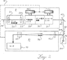
図2は、手動スポットサイズ調整システムのブロック図である;
図3は、代替コンポーネントの例を備えている手動スポットサイズ調整システムのブロック図である;
図4は、自動スポットサイズ調整システムのブロック図である;
図5は、光学記録システムsのスポットサイズを調整するための自動方法に対するフロー図である;
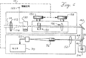
図6は、光音響モジュレータを組込んでいる手動スポットサイズ調整システムのブロック図である;
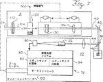
図7は、光音響モジュレータを組込んでいる自動スポットサイズ調整システムのブロック図である。
実施例
本発明の好ましい実施例を、全体を通して同じ番号が同じ部分を示すような図面を参照して説明する。
図1は、ブロック図形式で本発明の実施例を示している。図1のシステムは、ビームサイズ調整装置8、ビームスプリッタ50、画像装置10及び記録ヘッド54を含む。
図1の光ビーム14は、レーザ光源から放射されかつ情報で変調されたビームサイズ調整装置8に入力するか、またはそれは、以下に説明する代替の好ましい実施例と同様に、後で変調されうる。光ビーム14の大きさは、以下に説明する本発明の代替実施例によるビームサイズ調整装置8を用いて選択された大きさに設定される。ビームは、選択されたスポットサイズ直径を有するサイズドビーム40としてビームサイズ調整装置8を出る。
システムのコンポーネントの選択したレイアウトにより、サイズドビーム40は、ビームスプリッタ50へ一つ以上のミラー42によって指向される。ビームスプリッタ50は、ビーム40を、画像装置10に指向される測定ビーム44と記録ヘッドに指向される記録ビーム46とに分割する。好ましい実施例では、ビームスプリッタ50は、記録ビーム46が大きさにおいて測定ビーム44と等しいようにビームを分割する。
記録ビーム46は、光ビーム14の振幅変調によって決定されたパターンで記録媒体6に積層された感熱(heat sensitive)又は感光材料(photo sensitive material)に穴を焼き付けることによって記録媒体6に情報を記録するために用いられる。情報の記録は、また、フォトレジストのような感光材料(light sensitive material)に対する露光を伴う。
高精度ビームサイズ調整装置8をインプリメンテートする実施例では、ビームスプリッタ50及び画像装置10は、図1のシステムから省きうる。代替的に、画像装置10は、スポットの大きさ、又はビーム44の断面を測定することによって測定ビーム44に応答すべく追加されうる。画像装置10は、以下に説明する代替実施例と同様にスポットサイズを算出する。画像装置10は、画像装置10で行われた測定の結果によりスポットサイズの調整を可能にすべくビームサイズ調整装置8への帰還経路15を供給する。帰還経路15は、自動化されるか、またはそれは、手動でありうるし、選択円卓したスポットサイズを達成すべくビームサイズ調整装置8を調整するためにオペレータの介在を必要とする。
図2は、図1に関して説明された手動帰還経路15を用いている本発明の好ましい実施例を示す。図2のシステムでは、ビームサイズ調整装置8は、ビーム低減装置20及びビーム拡大装置30を備えている。光ビーム14は、ビーム低減装置20に指向される。ビーム低減装置20は、最初の直径から22における固定されたより小さい直径にビーム14の大きさを低減すべく組合せる集束レンズ21と第1のコリメータレンズ23を備えている。
好ましい実施例では、ビーム14は、スポットサイズの有用な範囲を得るために低減される。光ビーム14は、1.0mmのオリジナルの直径を有しかつビーム拡大装置30は、それが受け取るビームの直径の2倍から8倍のビームサイズを有する、ビームを放出する。考慮するスポット直径の範囲が1.0から4.0mmなので、オリジナルの1.0mmビームは、ビーム拡大装置30の全ての範囲が使用可能であるように22において0.5mmに低減される。
好ましい実施例のビーム拡大装置30は、可変拡大レンズ組立体33とコリメータレンズ組立体31を備えている。可変拡大レンズ組立体33は、ビームサイズアクチュエータ32を用いてオペレータによって手動で制御される。コリメータレンズ31は、コリメータアクチュエータ34を用いてオペレータによって手動で制御される。スペシャル・オプティクス(Special Optics,Inc.)によって製造されるモデル(Model)56-30-2-84のような、ビーム拡大装置30は、1.0mmビームが1.0mmから4.0mmに拡大されるような図2の実施例で必要なビーム拡大を達成するために用いられうる。
図2のビームサイズ調整装置8は、特定の初期ビーム直径用及びサイズド直径の特定の範囲用に構成される。当業者は、本発明の範疇から逸脱しない変形を理解できるであろう。変形の一例は、ビーム低減装置20の省略である。1から4倍の拡大範囲を有しているビーム拡大装置30が選択されたならば、興味がある1.0mmから4.0mmまでの全ての範囲を用いるためにビーム低減装置20は、必要ない。
サイズドビーム40は、ビームサイズアクチュエータ32のセッティングによって制御される可変拡大レンズ組立体33におけるレンズの位置に依存するビーム直径を有する。好ましい実施例では、ビームサイズアクチュエータ32は、特定のビームサイズによりインデックスが付される。オペレータは、所望のビームサイズのインデックスによりビームサイズアクチュエータ32を位置決めする。次いで、適当な大きさ及びコリメーションを達成することが必要であるならば、実際のビームサイズは、微細にチューンされうる。
コリメータレンズ組立体31は、光ビーム14を形成する光線(light rays)が平行であることを確実にするために用いられる。あまりよくコリメート(平行化)されていないビームは、スポットサイズによって設定された範囲を越えてさまよう光線を有する。スポットは、そのセットサイズよりも実際に大きく見える。可変拡大レンズ組立体33が適当にコリメートされたビームを生成するならば、コリメータレンズ組立体31は、省略されうる。好ましい実施例では、スポットのガウス型プロファイルが、所望の直径内に十分な光度が存在するということを示すならば、ビームは、適当にコリメートされる。可変拡大レンズ組立体31が特定のビームサイズを放出すべく設定される場合、コリメータレンズ組立体33が最小スポットサイズを有するスポットの画像を達成すべく調整されたときにコリメーションが達成される。
サイズドビーム40は、記録ビーム46を記録ヘッド54に通して渡すビームスプリッタ50に指向される。また、ビームスプリッタ50は、ビームサイズの精確な測定を得るために測定ビーム44を画像装置10に指向する。
図2の画像装置10は、対物レンズ52、顕微鏡対物レンズ56、CCDカメラ60及びモニタ70を含む。対物レンズ52は、顕微鏡対物レンズ56上に測定ビーム44を結像する。対物レンズ52、顕微鏡対物レンズ56及びCCDカメラ60は、無限大における対象物がCCDカメラ60に集束されるように位置合せされるテレスコープを構成する。対物レンズ52倍率及び顕微鏡対物レンズ56倍率が知られているので、CCDカメラ60は、測定ビーム44の実際の大きさと相関するモニタ70に画像(イメージ)を供給することができる。対物レンズ52、顕微鏡対物レンズ56及びCCDカメラ60で構成されたテレスコープが対象物を無限大にあるCCDカメラに集束すべく位置合せされないならば、画像サイズと実際のサイズとの間の相関は、ひっくり返される。
CCDカメラ60は、光軸に沿って光ビームの断面によって形成されたスポットの画像を捕らえる。オペレータは、モニタ70のような画像ビュー装置を用いてCCDカメラ60によって捕らえられた画像をビューしうる。画像ディジタイザのような、画像変換装置は、画像をビューするためにモニタ70に次いで指向されうるCCDカメラ60の電子表示にスポットの画像を変換するために用いることができる。また、画像フレーム取り込み装置は、瞬時におけるスポットの画像を記憶するために用いられうる。
代替実施例では、画像装置10は、スポットをアイピースを介して人間によってビュー可能な形に投影するレンズのシステムで実施されうる。
図2の手動モードシステムを用いて、オペレータは、ビームサイズアクチュエータ32を用いてビームサイズを調整しかつモニタ70上で結果をビューしうる。一度おおよそのスポットサイズが達成されたならば、オペレータは、ビデオモニタ70のビームスポット画像がその最小スポットサイズになるまでコリメーションアクチュエータ34を調整することによってビームが適格にコリメートされるということを確保しうる。このようにして、オペレータは、ビームサイズ及びコリメーションを正確に設定するための帰還経路15を供給する。
図2のシステムにおける変形は、本発明の範疇から逸脱することなく行いうるということが当業者によって容易に理解されるであろう。そのような変形の全てではないが、その一例が、図3を参照して説明される。
図3に示された一つの変形は、ビームサイズアクチュエータ32及びコリメータアクチュエータ34用のアクチュエータに関するものである。図2のビーム拡大装置30は、ビームサイズ及びコリメーションを調製するための手動的に制御されるアクチュエータ32,34を有している手動動作型ビーム拡大装置30である。手動アクチュエータ32,34は、カメラのビームシステムに用いられるモータに類似するモータシステムによって置き換えられうる。図3では、ビームサイズアクチュエータは、ビームサイズモータスイッチ37を用いてオン又はオフにされうるビームサイズモータ36を含む。図3の例では、ビームサイズモータスイッチ37は、一方向にスイッチを押すことによってスポットをより大きし、かつ反対方向にスイッチを押すことによってスポットをより小さくするためにユーザにビームサイジングレンズを移動させる。コリメーションアクチュエータは、コリメーションモータスイッチ39によって起動されるコリメーションモータ38を含む。
また、図3のシステムは、CCDカメラ60の画像がビューされうる方法に対する変形も示している。図3の画像ビュー装置72は、オペレータが視覚的にスポットの画像を測定することを容易にするような方法でスケール(計測)されるのが好ましいレチクル74を含む。
本発明の代替の好ましい実施例では、スポットサイズを調整する処理は、完全に自動化されうる。図4のスポットサイズ調整システムは、自動スポットサイズ調整システムの一例を示す。図4のシステムは、ビーム低減装置20,モータ制御式ビーム拡大装置30,ビームスプリッタ50,記録ヘッド54,対物レンズ52,顕微鏡対物レンズ56,CCDカメラ60,画像処理システム80及びモータコントローラシステム100を備えている。
図4のシステムは、自動オペレーションを許容する閉ループシステムである。図4の帰還経路15は、人間の介在なしで動作する。図4のシステムでは、CCDカメラ60は、画像処理システム80及びモータコントローラシステム100を有するコンピュータ78に結合される。
好ましい実施例のCCDカメラ60は、測定ビーム44によって形成されたスポットの画像のディジタル表示を出力する。測定ビーム44の断面のディジタル表示は、画像処理システム80の一部である画像処理ソフトウェアによる処理に対して修正可能なフォーマットであるのが好ましい。画像フレームグラバー及び画像処理ソフトウェアを備えている画像処理システムは、容易に利用可能である。フレームグラバー及びソフトウェアの一例は、Matrox,Inc.によって製造されているMeteor frame grabber及びImaging Libraryである。
代替的に、ソフトウェアは、あらゆる画像フォーマットを画像処理ソフトウェアによって直ぐに処理することができるフォーマットに変換すべく設計されうる。
画像処理システム80は、実質的に円形としてビームスポットの画像を処理しかつスポットサイズ計算機82は、ビームスポットによって形成された円形の直径を計算することによってスポットサイズを測定する。また、画像処理システム80は、直径により基準スポットサイズを受け入れて、スポットサイズ比較器は、スポットの実際の大きさを選択した基準スポットサイズと比較しうる。
次いで、画像処理システム80のソフトウェアは、実際のスポットサイズと基準サイズとの間の不一致を、ズームモータ36及びコリメーションモータ38を制御するモータコントローラシステム100に伝える。
図4の自動システムでは、オペレータは、基準スポットサイズを、画像処理システム80を有しているコンピュータ78に入力し、次いで、ズームモータ36及びコリメーションモータ38がよくコリメートされかつ正確なサイズのビーム44を供給すべくズーム及びコリメーションレンズ31,33を位置決めするまで待つ。図4のシステムにおける帰還経路15は、コンピュータ78のモータコントローラ100によりモータ36,38の制御によって供給される。
図5は、光学記録スポットの大きさを調整するための自動化方法を実施するフローチャートを示す。図4に示したシステムに類似する装置は、図5のフローチャートを実行するために使用しうる。
図5の処理は、オペレータがブロック200で示すようにスポットサイズがXであることを要求するときに開始する。画像は、現在のスポットサイズの測定の準備としてブロック210においてCCDカメラによって捕らえられる。ステップ210の処理は、バッファにCCDカメラ60のスポットの画像のディジタル表示を記憶するフレームグラバーによって実行されうる。ディジタルデータは、その直径によって測定されうるスポットとして画像処理ソフトウェアによって認識される。スポットサイズは、スポットサイズ計算機82によって220に示されるように測定される。
CCD上のスポットサイズの測定は、230でスポットサイズ比較器84によって要求されたスポットサイズと比較される。要求されたスポットサイズが測定されたスポットサイズに等しいならば、処理は、終了される。スポットサイズが異なるならば、比較は、ブロック240に示すように要求されたサイズが測定されたサイズよりも小さいかどうかを決定すべくチェックされる。要求されたサイズが小さいならば、倍率は、260に示すように減少される。要求されたサイズが大きいならば、倍率は、250に示すように増大される。
ステップ250における倍率を変える処理は、概算(推定)を含みうるしそこではモータコントローラ100は、スポットサイズが基準スポットサイズに等しくなるような点に倍率を設定するためにビームサイズモータ36を移動させる量を計算する。代替的に、モータは、所望のスポットサイズを得るまでステップ250が到達される毎に小さい増分で倍率を変更しうる。
倍率の調整が完了した後、コリメーションは、270に示すようにCCD上の現在の画像が最小サイズになるまで調整される。最小スポットサイズは、画像を連続的に捕らえ、各スポット画像を測定しかつ最新のスポットサイズと先のスポットサイズとの間の相違に応じてコリメーションモータ38を駆動することによって見出される。最小サイズが見出されたときに、制御は、処理が最初から開始される210に戻る。処理は、ブロック230で決定されるように要求されたスポットサイズが測定されたスポットサイズに等しくなるまで続く。所望のスポットサイズにおいてよくコリメートされたビームが達成された場合、情報を記憶する処理は、継続する。
本発明の他の代替実施例は、図6に示されている。図6の実施例は、変更機能をスポットサイジング機能と組み合わせる。機能の組み合わせは、スポットサイジング機能を実行するために必要なレンズの数の低減を結果として生ずる。図2〜図4に関して説明した好ましい実施例では、二つのレンズがビーム低減装置20で用いられかつ5つのレンズがビーム拡大装置30で用いられる。以下に説明する図6のシステムでは、スポットサイジング機能のレンズの数は、3に低減される。
図6のシステムでは、光ビーム14は、非変更状態のシステムに入力される。ビーム14は、光ビーム14を光音響モジュレータ120上に結像する結像レンズ112を通り抜ける。光音響モジュレータ120は、光ビームを含んでいる光媒体に存在する圧電材料を用いて音響波パターンを生成すべく情報信号122を受け取る。圧電材料によって生成された音響波は、正弦波回折格子のように動作する屈折率波を発生する。
好ましい実施例では、光音響モジュレータ120の動作は、レーザビームが情報信号122のディジタル的特質によってシャッタをオン及びオフする。ビーム信号の光度における充分に急峻な立ち上がり時間を確保するために、結像レンズ112は、ビームを光音響モジュレータ120のチャンバのある点に結像する。
光音響モジュレータ120によって出力される信号は、光ビームの大きさを設定するためにビームサイジングレンズ130に指向される。次いで、光ビームは、コリメータレンズ136に指向される。オペレータは、コリメータ及びサイジングアクチュエータ132,138を用いてサイジングレンズ130とコリメータレンズ136の両方の位置を制御しうる。130におけるビームサイジング及び136におけるビームコリメーションに対して選択されたレンズの仕様は、スポットサイズの所望の範囲及び二つのレンズの間の利用可能な距離に依存する。
コリメーティング及びサイジングレンズによって放出されるビームは、サイズドビーム40である。それは、サイズドビーム40をビームスプリッタ50へ更に指向するミラー42に指向されうる。ビームスプリッタ50は、サイズドビーム40を記録ヘッド54における対物レンズに指向される記録ビーム46、及び画像装置10に指向される測定ビーム44に分割する。図5の画像装置10は、結像レンズ52,顕微鏡対物レンズ56,CCDカメラ60及びモニタ70を備えている。
光音響モジュレータ120を利用している実施例は、図4に記述された実施例に類似するように動作すべく図6に示すように自動化されうる。図5のフローチャートに関して説明した処理は、図6に示した実施例によって実施されうる。
代替実施例は、本発明を実行するために説明された。本発明の範疇から逸脱することなく当業者が更なる変形を理解しうるということが理解されるべきである。
例えば、ビームサイズ調整装置は、可変倍率レンズ組立体33及びコリメーティングレンズ組立体31を有しているビーム拡大装置30を用いて動作するように説明された。一つの変形では、ビームサイズ調整装置8は、光ビーム14の直径を低減する。別の変形では、コリメーティングレンズ組立体31は、省略される。別の変形では、ガウス・プロファイルがステップよりもレンズによってより良く保存されるので光学記録システムにおいてレンズが好ましいけれども、ビームサイズ調整装置8は、レンズではなくビームの大きさを決めるためにストップを用いる。
画像装置10における更なる変形では、スポットの画像は、ビデオ波形モニタによって測定されうる。既知の光度を有している波形は、それによりスポットの直径を測定するためのスケールを供給しうる。
同様な変形が当業者によって本発明の他の部分においても理解できるであろう。 FIELD OF THE INVENTION The present invention relates generally to optical storage devices, and more particularly to a spot size adjustment system for an optical recording system.
Background of the invention The ongoing development of optical storage devices with larger storage capacities has resulted in the development of new optical formats. New optical formats are often needed to take advantage of advances in device physical capabilities.
At the data level, the optical format is defined by the data format used and the software used to translate the format. At the physical level, the optical format is defined by the physical capacity of the storage medium, such as the size of the information elements on the medium as well as the size of the spots formed by the light source used to scan the information elements. .
If improvements were made to allow for higher density media, a completely new format would be required even though the concept of device operation was the same. As a result, the recording systems for two different optical formats will each differ at a physical level that is only the size of the spot used to record the information.
The demand for high-capacity optical storage systems has encouraged the commercialization of new advances in optical formats to the extent that new formats are on the market before the old formats are no longer needed. The standard compact disc (CD) format was one of the first optical formats for storage devices. While CD continues to grow in the market, CD-R and other high density formats are also available.
The optical recording system used to manufacture the optical storage device is similar regardless of the optical format used. Increased density of information is often possible by using smaller recording spot sizes. At the data level, the ability to execute different algorithms on the same hardware allows different optical formats to be supported using a basic recording system. However, since each optical format can have a different recording spot size, the need for the optical recording system to perform different optical formats creates difficulties at the physical level.
One approach of the prior art is to stop manufacturing and change the hardware of the system that sets the recording spot size. This may include changing the lens or replacing a beam block having a different aperture size. However, this approach slows the recording process because the process must be stopped for hardware replacement and calibration required by the new spot size.
Since optical storage technology continues to advance and the master optical recording system often needs to support a number of different optical formats, a method of changing the recording spot size quickly and easily is desirable.
Objects and overview In view of the above, one object of the present invention is to provide a system for adjusting the spot size of an optical recording system using a beam size adjustment device. The beam size actuator controls the beam size adjustment device to allow the operator to achieve the desired spot size.
Another object of the present invention is to provide a closed loop optical recording system to allow spot size adjustment without user intervention. The beam size adjusting device is controlled by a corresponding motor. The imaging device captures an image of the cross section of the recording beam. Image processing software measures the spot size and compares the measurement to a selected reference spot size. The motor interface controls the beam size adjustment motor to increase or decrease the spot according to the difference between the actual spot and the reference spot size.
It is a further object of the present invention to provide a method for adjusting the spot size of an optical recording system by selecting the spot size and adjusting the beam size to be equal to the spot size. The beam size is adjusted by measuring the current beam size, comparing the actual size with the selected spot size and controlling the beam size adjuster.
It is a further object of the present invention to integrate a photoacoustic modulator with a three-lens spot sizing system for combination with an automatic image processor to provide a closed loop system or a manual imager to provide an open loop spot sizing system. (Integrating).
[Brief description of the drawings]
FIG. 1 is a block diagram of an example of an optical spot size adjustment system of the present invention;
FIG. 2 is a block diagram of a manual spot size adjustment system;
FIG. 3 is a block diagram of a manual spot sizing system with examples of alternative components;
FIG. 4 is a block diagram of an automatic spot size adjustment system;
FIG. 5 is a flow diagram for an automatic method for adjusting the spot size of the optical recording system s;
FIG. 6 is a block diagram of a manual spot size adjustment system incorporating a photoacoustic modulator;
FIG. 7 is a block diagram of an automatic spot size adjustment system incorporating a photoacoustic modulator.
Embodiments Preferred embodiments of the invention will now be described with reference to the drawings wherein like numerals indicate like parts throughout.
FIG. 1 shows an embodiment of the invention in block diagram form. The system of FIG. 1 includes a beam
The
Depending on the selected layout of the components of the system, the
The
In an embodiment that implements the high precision beam
FIG. 2 shows a preferred embodiment of the present invention using the
In the preferred embodiment, the
The beam
The
The
The
The
The
The
In an alternative embodiment, the
Using the manual mode system of FIG. 2, the operator can adjust the beam size using the beam size actuator 32 and view the results on the
It will be readily appreciated by those skilled in the art that variations in the system of FIG. 2 can be made without departing from the scope of the present invention. An example, if not all, of such variations is described with reference to FIG.
One variation shown in FIG. 3 relates to actuators for the beam size actuator 32 and the collimator actuator 34. The
The system of FIG. 3 also shows a variation on the way in which the image of the
In an alternative preferred embodiment of the present invention, the process of adjusting the spot size can be fully automated. The spot size adjustment system of FIG. 4 shows an example of an automatic spot size adjustment system. 4 includes a
The system of FIG. 4 is a closed loop system that allows automatic operation. The
The
Alternatively, the software can be designed to convert any image format into a format that can be immediately processed by the image processing software.
The software of the
In the automated system of FIG. 4, the operator enters the reference spot size into a
FIG. 5 shows a flowchart for implementing an automated method for adjusting the size of the optical recording spot. An apparatus similar to the system shown in FIG. 4 may be used to perform the flowchart of FIG.
The process of FIG. 5 begins when the operator requests that the spot size be X as indicated by
The spot size measurement on the CCD is compared at 230 with the spot size requested by the
The process of changing the magnification in
After the magnification adjustment is complete, the collimation is adjusted until the current image on the CCD is at a minimum size as shown at 270. The minimum spot size is found by continuously capturing images, measuring each spot image and driving the
Another alternative embodiment of the present invention is shown in FIG. The embodiment of FIG. 6 combines the change function with the spot sizing function. The combination of functions results in a reduction in the number of lenses required to perform the spot sizing function. In the preferred embodiment described with respect to FIGS. 2-4, two lenses are used in the
In the system of FIG. 6, the
In the preferred embodiment, the operation of the
The signal output by the
The beam emitted by the collimating and sizing lens is a
An embodiment utilizing the
Alternative embodiments have been described to implement the present invention. It should be understood that further variations can be understood by those skilled in the art without departing from the scope of the invention.
For example, the beam size adjustment device has been described to operate using a
In a further variation on the
Similar variations will be apparent to those skilled in the art in other parts of the invention.
Claims (18)
ビームリデューサおよびビームエクスパンダを備え、光ビームを受け取りかつ記録ヘッドの方向に向けられたコリメートされたサイズドビームを放出するように配置されたビームサイズ調整装置であり、前記サイズドビームの前記サイズが可動レンズの位置に応答する、該ビームサイズ調整装置と、
位置の範囲にわたり前記可動レンズの位置を調整するように動作するアクチュエータであり、各位置がスポットサイズの範囲の一つに対応している、該アクチュエータと、
前記サイズドビームの断面の画像を捕らえるように配置された画像装置と、
前記サイズドビームの画像を該サイズドビームの該画像の電子表示に変換するように動作する画像トランスレータと、
前記サイズドビームが前記記録ヘッドに入射する直前に設けられ、前記記録媒体に指向された第1の部分及び前記画像装置に指向された第2の部分に分割するビームスプリッタを有し、
前記画像装置は、さらに分離された前記第2のサイズドビームが指向され、対物レンズ、顕微鏡対物レンズ、電荷結合素子カメラで構成されたテレスコープを含むことを特徴とする調整システム。In an optical recording system, a system for adjusting the size of an optical recording spot of a recording beam formed on an information recording medium through a recording head ,
A beam sizing device comprising a beam reducer and a beam expander, arranged to receive a light beam and emit a collimated sized beam directed in the direction of the recording head, the size of the sized beam The beam size adjustment device responsive to the position of the movable lens;
Wherein over a range of positions an actuator operable to adjust the position of the movable lens, each position corresponding to one of a range of spot size, and the actuator,
An imaging device arranged to capture an image of a cross-section of the sized beam;
An image translator operable to convert the image of the sized beam into an electronic representation of the image of the sized beam;
A beam splitter that is provided immediately before the sized beam is incident on the recording head, and that divides the beam into a first portion directed to the recording medium and a second portion directed to the image device;
The adjustment system according to claim 1, wherein the imaging apparatus further includes a telescope that is directed to the separated second sized beam and includes an objective lens, a microscope objective lens, and a charge coupled device camera .
前記サイズドビームの断面を表現するように動作する画像ビューワと、
前記画像ビューワ上のレチクルとを更に備えることを特徴とする請求項1に前記の調整システム。The image device includes:
An image viewer that operates to represent a cross-section of the sized beam;
The adjustment system according to claim 1, further comprising a reticle on the image viewer.
オペレータ制御式サイズ調整装置アクチュエータに応答する可変拡大レンズ組立体と、
オペレータ制御式コリメータアクチュエータによる調整に応答するコリメータレンズ組立体とを備えることを特徴とする請求項1に記載の調整システム。The beam size adjusting device includes:
A variable magnifying lens assembly responsive to an operator controlled size adjuster actuator;
The adjustment system according to claim 1, further comprising a collimator lens assembly responsive to adjustment by an operator-controlled collimator actuator.
前記画像装置は、
前記サイズドビームの画像を該サイズドビームの該画像の電子表示に変換するように動作する画像トランスレータと、
前記サイズドビームの前記画像の前記電子表示に応答する画像プロセッサであり、実際のビームサイズを決定するように動作するスポットサイズ計算機、及び前記実際のビームサイズと選択したスポットサイズとの間の相違を決定するように動作するスポット比較器を備える、該画像プロセッサとを更に備え、
前記アクチュエータは、
前記スポット比較器によって決定された前記相違に応じて前記第1のモータを制御するように動作する第1のコントローラを備える、
ことを特徴とする請求項1に記載の調整システム。The beam size adjusting device includes a first motor that operates to adjust the beam size adjusting device;
The image device includes:
An image translator operable to convert the image of the sized beam into an electronic representation of the image of the sized beam;
An image processor responsive to the electronic representation of the image of the sized beam, a spot size calculator operating to determine an actual beam size, and a difference between the actual beam size and a selected spot size Said image processor comprising a spot comparator operable to determine
The actuator is
Comprising a first controller operable to control the first motor in response to the difference determined by the spot comparator;
The adjustment system according to claim 1 .
ビームリデューサ及びビームエクスパンダを備えている第1のレンズ組立体を通して光ビームをパスする段階と、
前記レンズ組立体の可動レンズの位置に応じて前記ビームの大きさを決める段階と、
前記第1のレンズ組立体からコリメートされたサイズドビームを放出する段階と、
記録ヘッドに向けて前記サイズドビームをパスする段階と、及び前記可動レンズに動作可能に接続された第1のアクチュエータを選択したスポットサイズに対応する位置に設定する段階であり各位置がスポットサイズの範囲の一つに対応している該段階と、
前記光ビームを前記記録媒体に指向された第1の部分及び前記画像装置に指向された第2の部分に分割する段階と、
前記光ビームの一部を用いて記録媒体上に記録する段階と、
前記分離された前記サイズドビームの第1の部分は、さらに対物レンズ、顕微鏡対物レンズ、電荷結合素子カメラで構成されたテレスコープに指向される段階を具備することを特徴とする方法。A method for adjusting a recording spot size in an optical recording system, comprising:
Passing the light beam through a first lens assembly comprising a beam reducer and a beam expander;
Determining the size of the beam according to the position of the movable lens of the lens assembly;
Emitting a collimated sized beam from the first lens assembly;
Passing the sized beam toward the recording head, and setting a first actuator operably connected to the movable lens to a position corresponding to the selected spot size, each position being a spot size and said step of one to correspond to the range of,
Splitting the light beam into a first portion directed to the recording medium and a second portion directed to the imaging device;
Recording on a recording medium using a portion of the light beam;
The method of claim 1, further comprising the step of directing the separated first portion of the sized beam to a telescope comprising an objective lens, a microscope objective lens, and a charge coupled device camera .
Applications Claiming Priority (3)
| Application Number | Priority Date | Filing Date | Title |
|---|---|---|---|
| US65777696A | 1996-05-31 | 1996-05-31 | |
| US08/657,776 | 1996-05-31 | ||
| PCT/US1997/009143 WO1997045835A1 (en) | 1996-05-31 | 1997-05-30 | System for adjusting the spot size in an optical recording system |
Publications (3)
| Publication Number | Publication Date |
|---|---|
| JP2000511325A JP2000511325A (en) | 2000-08-29 |
| JP2000511325A5 JP2000511325A5 (en) | 2005-01-13 |
| JP4175580B2 true JP4175580B2 (en) | 2008-11-05 |
Family
ID=24638620
Family Applications (1)
| Application Number | Title | Priority Date | Filing Date |
|---|---|---|---|
| JP54293397A Expired - Fee Related JP4175580B2 (en) | 1996-05-31 | 1997-05-30 | System for adjusting spot size of optical recording system |
Country Status (6)
| Country | Link |
|---|---|
| US (1) | US5889750A (en) |
| EP (1) | EP0902945B1 (en) |
| JP (1) | JP4175580B2 (en) |
| AU (1) | AU3147897A (en) |
| DE (1) | DE69731630T2 (en) |
| WO (1) | WO1997045835A1 (en) |
Families Citing this family (14)
| Publication number | Priority date | Publication date | Assignee | Title |
|---|---|---|---|---|
| US6455838B2 (en) * | 1998-10-06 | 2002-09-24 | The Regents Of The University Of California | High sensitivity deflection sensing device |
| JP2002237076A (en) * | 2001-02-06 | 2002-08-23 | Pioneer Electronic Corp | Aberration correcting device |
| GB0127573D0 (en) * | 2001-11-17 | 2002-01-09 | Corning Inc | Semiconductor optical devices and methods of making them |
| US7129503B2 (en) | 2002-10-09 | 2006-10-31 | Hewlett-Packard Development Company, L.P. | Determining emitter beam size for data storage medium |
| JP4843344B2 (en) * | 2005-03-18 | 2011-12-21 | 株式会社リコー | Illumination device and image reading device |
| EP2790570B1 (en) | 2011-12-05 | 2019-09-04 | Bioptigen, Inc. | Optical imaging systems having input beam shape control and path length control |
| US8777412B2 (en) | 2012-04-05 | 2014-07-15 | Bioptigen, Inc. | Surgical microscopes using optical coherence tomography and related methods |
| EP3003123B1 (en) | 2013-06-04 | 2020-08-19 | Bioptigen, Inc. | Optical coherence tomography imaging system and optical laser scanning system comprising a beam shaping optical system with a +-+ lens triplet, where second and third lens are movable, and method |
| CN105592829B (en) | 2013-07-29 | 2018-11-16 | 拜尔普泰戈恩公司 | Surgical optical coherence tomography (OCT) and its related system and method for surgical operation |
| EP3039474A1 (en) | 2013-08-28 | 2016-07-06 | Bioptigen, Inc. | Heads up displays for optical coherence tomography integrated surgical microscopes |
| IL233692A (en) * | 2014-07-17 | 2017-04-30 | Elbit Systems Electro-Optics Elop Ltd | System and method for analyzing quality criteria of a radiation spot |
| CN108732712B (en) * | 2018-05-25 | 2020-09-15 | 歌尔股份有限公司 | Optical path adjusting method and optical path adjusting device |
| CN108732711B (en) * | 2018-05-25 | 2021-11-30 | 歌尔光学科技有限公司 | Optical path adjusting method and optical path adjusting device |
| JP2021089383A (en) * | 2019-12-05 | 2021-06-10 | 株式会社ディスコ | Laser beam adjustment mechanism and laser processing apparatus |
Family Cites Families (21)
| Publication number | Priority date | Publication date | Assignee | Title |
|---|---|---|---|---|
| US4272651A (en) * | 1978-04-28 | 1981-06-09 | Matsushita Electric Industrial Co., Ltd. | Optical system having diode laser light source |
| US4381557A (en) * | 1980-12-19 | 1983-04-26 | Rca Corporation | Optical focus sensor |
| DE3445342A1 (en) * | 1983-12-12 | 1985-06-20 | Asahi Kogaku Kogyo K.K., Tokio/Tokyo | Laser beam exposing system |
| JPS60124939A (en) * | 1983-12-12 | 1985-07-04 | Asahi Optical Co Ltd | Laser exposure device |
| JPS63100620A (en) * | 1986-06-20 | 1988-05-02 | Sanyo Electric Co Ltd | Optical pick-up device |
| US4998234A (en) * | 1987-03-31 | 1991-03-05 | Rees Theodore D | Logarithmic servo error detection for optical disk drive |
| JPH01105338A (en) * | 1987-07-14 | 1989-04-21 | Mitsubishi Electric Corp | Optical recording and reproducing device |
| GB2209089B (en) * | 1987-08-26 | 1991-07-03 | Sony Corp | Optical recording and/or reproducing apparatus. |
| US5101392A (en) * | 1988-11-21 | 1992-03-31 | Kabushiki Kaisha Toshiba | Information recording apparatus |
| NL8803012A (en) * | 1988-12-08 | 1990-07-02 | Philips Nv | Optical scanning device provided with a focusing control system and an integrated circuit for use in the focusing control system. |
| US5172369A (en) * | 1990-03-02 | 1992-12-15 | Pioneer Electronic Corporation | Optical pickup, optical information recording carrier and recording and reproducing apparatus thereof |
| US5164932A (en) * | 1990-09-28 | 1992-11-17 | International Business Machines Corporation | Acquiring a best focus using a focus signal offset |
| GB2251514B (en) * | 1990-10-23 | 1994-09-21 | Asahi Optical Co Ltd | Optical disk apparatus, and construction of optical disk |
| JP2820808B2 (en) * | 1991-03-29 | 1998-11-05 | コニカ株式会社 | Focus control mechanism of optical disk device |
| US5233585A (en) * | 1991-09-11 | 1993-08-03 | International Business Machines Corporation | Acquiring focus in an optical disk system using a time and shape modified focus error signal |
| US5359588A (en) * | 1992-02-12 | 1994-10-25 | Mitsubishi Denki Kabushiki Kaisha | Optical recording/reproducing apparatus |
| JPH05242521A (en) * | 1992-02-27 | 1993-09-21 | Pioneer Electron Corp | Optical disk player |
| JP2720749B2 (en) * | 1993-03-11 | 1998-03-04 | 松下電器産業株式会社 | Light spot distortion measurement adjustment device |
| DE4308531A1 (en) * | 1993-03-17 | 1994-09-22 | Thomson Brandt Gmbh | Compatible recording and / or playback device |
| US5367513A (en) * | 1993-11-05 | 1994-11-22 | International Business Machines Corporation | Focus and tracking servo decoupling system |
| US5425013A (en) * | 1993-11-12 | 1995-06-13 | International Business Machines Corporation | Relative position sensing calibration for optical storage device |
-
1997
- 1997-05-30 WO PCT/US1997/009143 patent/WO1997045835A1/en active IP Right Grant
- 1997-05-30 EP EP97926799A patent/EP0902945B1/en not_active Expired - Lifetime
- 1997-05-30 DE DE69731630T patent/DE69731630T2/en not_active Expired - Lifetime
- 1997-05-30 JP JP54293397A patent/JP4175580B2/en not_active Expired - Fee Related
- 1997-05-30 AU AU31478/97A patent/AU3147897A/en not_active Abandoned
- 1997-11-07 US US08/967,294 patent/US5889750A/en not_active Expired - Lifetime
Also Published As
| Publication number | Publication date |
|---|---|
| EP0902945A1 (en) | 1999-03-24 |
| DE69731630T2 (en) | 2005-12-01 |
| JP2000511325A (en) | 2000-08-29 |
| EP0902945A4 (en) | 1999-09-22 |
| US5889750A (en) | 1999-03-30 |
| AU3147897A (en) | 1998-01-05 |
| WO1997045835A1 (en) | 1997-12-04 |
| EP0902945B1 (en) | 2004-11-17 |
| DE69731630D1 (en) | 2004-12-23 |
Similar Documents
| Publication | Publication Date | Title |
|---|---|---|
| JP4175580B2 (en) | System for adjusting spot size of optical recording system | |
| AU2002313824B2 (en) | Ophthalmic wavefront measuring devices | |
| US6992779B2 (en) | Interferometer apparatus for both low and high coherence measurement and method thereof | |
| US4863252A (en) | Objective lens positioning system for confocal tandem scanning reflected light microscope | |
| AU2002313824A1 (en) | Ophthalmic wavefront measuring devices | |
| JP2019113554A (en) | Variable focal length lens system including focal state reference subsystem | |
| JP2008523370A (en) | Measuring apparatus and method based on basic principle of confocal microscope system | |
| JPS60115907A (en) | Automatic focus adjustor for optical apparatus | |
| JP2018159704A (en) | Modulation monitoring system for use with imaging system that includes variable focal length lens having high-speed periodically modulated focus position | |
| JPH11218686A (en) | Optical image recording device and method utilising the device | |
| US6738323B1 (en) | Optical disc apparatus and focusing control method in an optical disc apparatus | |
| US5113385A (en) | Optical disk cutting apparatus | |
| JP2020106841A (en) | System and method for calibrating variable focal length lens system by using calibration object with planar tilted pattern surface | |
| TW202246762A (en) | Three-dimensional imaging with enhanced resolution | |
| TW445441B (en) | Method and apparatus for exposing master disk for optical disk | |
| JP2004271365A (en) | Aberration-measuring apparatus, aberration-measuring method, optical head rigging apparatus, and optical head adjusting method | |
| JP2004253020A (en) | Method and device to adjust focal position of optical pickup | |
| JP4656880B2 (en) | Optical pickup outgoing light measuring device and adjustment method | |
| JP4656879B2 (en) | Optical pickup outgoing light measuring device and measuring method | |
| JPH06180855A (en) | Device for evaluating optical head | |
| JPH0415535A (en) | Optical characteristic measuring instrument for optical information storage device | |
| JPH11283268A (en) | Method and device to adjust optical head system | |
| JP2001108877A (en) | Method and device for adjusting optical unit | |
| JPH07220287A (en) | Position adjusting method for optical path in exposure device | |
| JP3273509B2 (en) | Focus detection device |
Legal Events
| Date | Code | Title | Description |
|---|---|---|---|
| A521 | Request for written amendment filed |
Free format text: JAPANESE INTERMEDIATE CODE: A523 Effective date: 20040531 |
|
| A621 | Written request for application examination |
Free format text: JAPANESE INTERMEDIATE CODE: A621 Effective date: 20040531 |
|
| A131 | Notification of reasons for refusal |
Free format text: JAPANESE INTERMEDIATE CODE: A131 Effective date: 20080122 |
|
| A521 | Request for written amendment filed |
Free format text: JAPANESE INTERMEDIATE CODE: A523 Effective date: 20080422 |
|
| RD02 | Notification of acceptance of power of attorney |
Free format text: JAPANESE INTERMEDIATE CODE: A7422 Effective date: 20080422 |
|
| RD04 | Notification of resignation of power of attorney |
Free format text: JAPANESE INTERMEDIATE CODE: A7424 Effective date: 20080422 |
|
| TRDD | Decision of grant or rejection written | ||
| A01 | Written decision to grant a patent or to grant a registration (utility model) |
Free format text: JAPANESE INTERMEDIATE CODE: A01 Effective date: 20080812 |
|
| A01 | Written decision to grant a patent or to grant a registration (utility model) |
Free format text: JAPANESE INTERMEDIATE CODE: A01 |
|
| A61 | First payment of annual fees (during grant procedure) |
Free format text: JAPANESE INTERMEDIATE CODE: A61 Effective date: 20080818 |
|
| FPAY | Renewal fee payment (event date is renewal date of database) |
Free format text: PAYMENT UNTIL: 20110829 Year of fee payment: 3 |
|
| R150 | Certificate of patent or registration of utility model |
Free format text: JAPANESE INTERMEDIATE CODE: R150 |
|
| FPAY | Renewal fee payment (event date is renewal date of database) |
Free format text: PAYMENT UNTIL: 20110829 Year of fee payment: 3 |
|
| FPAY | Renewal fee payment (event date is renewal date of database) |
Free format text: PAYMENT UNTIL: 20120829 Year of fee payment: 4 |
|
| FPAY | Renewal fee payment (event date is renewal date of database) |
Free format text: PAYMENT UNTIL: 20120829 Year of fee payment: 4 |
|
| FPAY | Renewal fee payment (event date is renewal date of database) |
Free format text: PAYMENT UNTIL: 20130829 Year of fee payment: 5 |
|
| LAPS | Cancellation because of no payment of annual fees |