JP4174251B2 - Drug cassette - Google Patents
Drug cassette Download PDFInfo
- Publication number
- JP4174251B2 JP4174251B2 JP2002202758A JP2002202758A JP4174251B2 JP 4174251 B2 JP4174251 B2 JP 4174251B2 JP 2002202758 A JP2002202758 A JP 2002202758A JP 2002202758 A JP2002202758 A JP 2002202758A JP 4174251 B2 JP4174251 B2 JP 4174251B2
- Authority
- JP
- Japan
- Prior art keywords
- medicine
- rotor
- notch
- reference bottom
- cassette
- Prior art date
- Legal status (The legal status is an assumption and is not a legal conclusion. Google has not performed a legal analysis and makes no representation as to the accuracy of the status listed.)
- Expired - Fee Related
Links
Images


Description
【0001】
【発明の属する技術分野】
本発明は、収容する薬剤を所定量毎に排出し得るように構成された薬剤カセッタに関する。
【0002】
【従来の技術】
収容する薬剤を所定量毎に排出し得るように構成された薬剤カセッタは、薬剤選択供給装置の一構成部品として使用されている。
即ち、該薬剤選択供給装置は、ドラム等の支持架台と、該支持架台に装着される複数のカセッタであって、それぞれ所定の薬剤が収容された複数のカセッタとを備えている。該カセッタは、例えば、前記支持架台に取り付けられるベース部材に着脱可能に装着される。
前記薬剤選択供給装置は、使用に際して、処方に基づくオペレータからの選択信号により、対応する一のカセッタを選択的に駆動する。これにより、該一のカセッタにおけるロータが回転し、収容された薬剤が必要量だけ自動的に排出される。
【0003】
より詳しくは、前記カセッタは、収容部と、該収容部内において回転駆動されるロータとを備えている。該ロータには、収容する薬剤を保持する為の切り欠きが設けられている。他方、前記収容部には、該ロータの切り欠きの回転軌跡に対応した位置に排出口が設けられている。
さらに、該収容部には、前記切り欠きに保持された薬剤のうち一度に排出させる数量を制限する係止片を有している。例えば、ロータの回転に応じて薬剤を一錠毎に排出させる場合には、前記係止片は、該ロータの切り欠きに保持された薬剤のうち最も下方に位置する第1薬剤の高さに対応した位置に設けられている。斯かる構成により、前記ロータが回転されて前記切り欠きが収容部に設けられた排出口に位置合わせされると、該切り欠きに保持された第1薬剤のみが排出口から排出される。
【0004】
【発明が解決しようとする課題】
ところで、前記カセッタに収容される薬剤は種々の形状を有している。例えば、錠剤を半分に切断してなる半錠の場合には、前記切り欠きに保持される際の姿勢が一定ではなく、底面を下にした姿勢(図6(a)参照)や切断面を下にした起立姿勢(図6(b)参照)をとり得る。従って、斯かる薬剤の場合に前記係止片を設けても、該係止片より下方に複数の薬剤が入り込んだり、若しくは、該係止片によって薬剤が損傷を受ける恐れがある。
本発明は、斯かる従来技術に鑑みなされたものであり、薬剤の形状に拘わらず、ロータの回転に応じて薬剤を必要個数ずつ正確に排出できる構造簡単な薬剤カセッタを提供することを一の目的とする。
【0005】
【課題を解決するための手段】
本発明は、前記目的を達成するために、収容された薬剤を所定量毎に排出し得るように構成された薬剤カセッタであって、傾斜された基準底面と、該基準底面との共働下に薬剤収容空間を形成する側面とを有する収容部と、回転軸線が前記収容部の基準底面と直交するように、該基準底面に対して回転可能とされたロータとを備え、前記ロータは、収容される薬剤が挿通可能な大きさの切り欠きを有し、前記収容部の基準底面には、前記ロータにおける前記切り欠きの回転軌跡に対応した領域のうち最も下方に位置する最下方領域よりも上方に、排出口が設けられており、さらに、前記収容部の基準底面には、前記ロータの回転方向を基準として、前記最下方領域と前記排出口との間に、前記ロータへ向かって突出した凸部が設けられている薬剤カセッタを提供する。
【0006】
好ましくは、前記収容部は、前記基準底面を形成する底板部材と、前記側面を形成する収容部本体とを有し、前記底板部材は前記収容部本体に着脱可能に固定され得る。
又、好ましくは、前記切り欠きは、前記ロータの周縁に開くように形成され得る。
【0007】
【発明の実施の形態】
以下に、本発明に係る薬剤カセッタの好ましい一実施の形態について、添付図面を参照しつつ説明する。
図1は、本実施の形態に係る薬剤カセッタ1がベース部材100に載置された状態で、ドラム等の支持架台200に取り付けられている様子を示す部分縦断側面図である。
【0008】
前記ベース部材100は、好ましくは、前記支持架台200にネジ連結されるように構成され、前記薬剤カセッタ1は、弾性係合又は磁力係合を介して、該ベース部材100に着脱可能に装着される。
【0009】
前記カセッタ1は、薬剤収容空間を有する収容部10と、該薬剤収容空間内に配設されるロータ20とを備えている。
前記収容部10は、水平面に対して所定角度(例えば、40〜50゜)傾斜された基準底面11と、該基準底面11との共働下に前記薬剤収容空間を形成する側面12とを有している。
好ましくは、基準底面11を平面視円形状とし、且つ、前記側面12を該基準平面11の周縁から該基準平面に対して直交するように延在させることができ、これにより、前記薬剤収容空間を略円筒形状とすることができる。
【0010】
図2に図1におけるII矢視図を示す。又、図3に図2におけるIII-III線断面図を示す。
前記ロータ20は、回転軸線Xが前記基準底面11と直交するように、該基準底面11上に位置するディスク部21と、該ディスク部21の中心から前記薬剤収容空間とは反対側に延び、前記基準底面11に設けられた支持孔に回転自在に挿通される支持部25とを備えている
【0011】
より詳しくは、前記支持部25には、一端部に従動側ベベルギヤ27が設けられた従動軸26が固着されており、該従動側ベベルギヤ27は、前記ベース部材100に収容されたモータ(図示せず)に作動的に連結された駆動側ベベルギヤ110と噛合している。
なお、当然ながら、前記モータと前記ロータとの間の伝動機構は、図示の形態におけるように、歯車を利用したものの他、ベルト又は自在継手を利用して構成し得る。
【0012】
図2及び図3に示すように、前記ロータ20のディスク部21には、収容される薬剤を所定個数(例えば1個)ずつ挿通可能な切り欠き22が設けられている。即ち、該切り欠き22内に入り込んだ薬剤だけが該切り欠き22と基準底面11とにより保持されて、ディスク部21の回転に伴って周方向に搬送される。
【0013】
好ましくは、前記切り欠き22は、該ディスク部21の周縁に開くように形成される。このように構成することによって、薬剤収容部内の下方領域に集まった薬剤を効率良く切り欠き22内に入り込ませることができる。
より好ましくは、該切り欠き22は、ディスク部21の周方向に沿って等間隔に複数設けることができる。
【0014】
図3に示すように、該ロータ20のディスク部21は、少なくとも前記切り欠き22においては、前記基準底面11に対して間隙50を存しつつ離間されている。該間隙50は、例えば、0.5〜1.5mmとされる。
好ましくは、前記ディスク部21は、前記切り欠き22の回転軌跡に対応した領域以外において、前記基準底面11と当接する当接部23を有している。斯かる当接部23を備えることにより、前記基準底面11に対してディスク部21を安定して回転させることができる。
【0015】
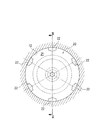
図4に前記ロータを取り外した状態のII矢視図を示す。又、図5に図4におけるV-V線断面図を示す。
図4に示すように、前記収容部10の基準底面11には、前記ロータ20における前記切り欠き22の回転軌跡22aに対応した領域のうち最も下方に位置する領域(以下、最下方領域という)よりも上方に、排出口15が設けられている。該排出口15は、例えば、前記切り欠き22の回転軌跡22aに対応した領域のうち最も上方に位置する領域(以下、最上方領域という)に形成される。
【0016】
即ち、本実施の形態に係る薬剤カセッタ1においては、前記切り欠き22に保持され、ロータ20の回転に応じて周方向に搬送される薬剤は、前記排出口15を介してカセッタ1から排出される。なお、前記排出口15は前記ベース部材100に形成された搬送路120に連通されており(図1参照)、カセッタ1から排出された薬剤は、該搬送路120に連通されるホッパ(図示せず)を介して分包装置(図示せず)へ供給される。
【0017】
さらに、前記収容部10の基準底面11には、前記切り欠き22の回転軌跡22aに対応した領域のうち、前記ロータ20の回転方向(図4における矢印方向)を基準として、前記最下方領域と前記排出口15との間に、前記ロータ20へ向かって突出した凸部18が設けられている。該凸部18は、例えば、0.3〜1.3mmの高さを有するものとされる。
好ましくは、前記凸部18は、前記切り欠き22の回転軌跡22aに対応した領域のうち、ロータの回転軸線Xよりも上方に位置した領域に形成される。
【0018】
以下、斯かる構成の薬剤カセッタ1の動作について、収容する薬剤を1錠ずつ排出させる場合を例に説明する。
前記薬剤収容空間内に収容された薬剤は、重力によって、下方領域に集まり、該下方領域に位置する切り欠き22内に入り込む。
該切り欠き22内に入り込んだ薬剤は、該切り欠き22と前記基準底面11及び側面12との共働下に保持され、ロータ20の回転に応じて切り欠き22の回転軌跡に沿って搬送される。即ち、切り欠き22内の薬剤は、前記基準底面11及び側面12に当接した状態で、ロータ20の回転方向に搬送される。
【0019】
ところで、前記切り欠き22の形状を、収容する薬剤1錠だけが入り込むように設計することは非常に困難である。特に、収容する薬剤が、偏平状の錠剤を半分に切断してなる半錠のような場合(図6参照)には、前記切り欠き22内に入り込む際の薬剤の姿勢が一定でなく、従って、1つの切り欠きによって複数の薬剤が保持される恐れがある。
又、通常の錠剤を収容する場合であっても、薬剤同士間の摩擦等によって、切り欠き内に入り込んだ一の薬剤の上に他の薬剤が載った状態で、2個以上の薬剤が搬送される場合がある。このような場合、前記排出口15から一の薬剤と他の薬剤との2錠が同時に排出されることになる。
【0020】
これに対し、本実施の形態においては、前述の通り、前記基準底面11のうち、前記切り欠き22の回転軌跡22aに対応した領域に凸部18を設けている。その為、切り欠き22内に入り込んだ一の薬剤は、前記凸部18を通過する際に上方へ持ち上げられ、その結果、該一の薬剤の上に載った他の薬剤はディスク部21の傾斜に沿って下方へ滑り落ちる。
【0021】
このように、本実施の形態においては、前記凸部18を設けることにより、切り欠き22内に入り込んだ一の薬剤と該一の薬剤の上に載った他の薬剤とが同時に前記排出口から排出されることを有効に防止できる。
【0022】
なお、前記切り欠き22の形状は、該切り欠き内に複数個の薬剤が入り込むのを防止すべく、収容する錠剤が切り欠き内に入り込む際の外形状に応じて適宜設定されるが、収容する薬剤が図6に示すような半錠の場合には、前述の通り、切り欠き内に入り込む際の薬剤の姿勢は一定にはならない。
そこで、斯かる半錠を収容する場合には、前記切り欠き22の形状を、半錠の断面形状と半錠の平面形状とを重合させた形状とすることができ(図2参照)、これにより、切り欠き内へ1個の半錠のみを容易に入り込ませることができる。
【0023】
又、本実施の形態においては、前記基準底面11を薬剤収容部10に一体的に形成した場合を例に説明したが、本発明は斯かる形態に限定されるものではない。即ち、前記基準底面11を形成する部材を薬剤収容部の本体とは別体とし、該部材を薬剤収容部の本体に装着させることも可能である。
【0024】
【発明の効果】
以上のように、本発明に係る薬剤カセッタによれば、薬剤収容部における傾斜された基準底面のうち,ロータに設けられた切り欠きの回転軌跡に対応した位置に、凸部を設けたので、前記切り欠きによって搬送される不要な薬剤が排出口から排出されることを有効に防止できる。
【図面の簡単な説明】
【図1】図1は、本発明の一実施の形態に係る薬剤カセッタの部分縦断側面図であり、ベース部材を介して支持架台に取り付けられている状態を示している。
【図2】図2は、図1におけるII矢視図である。
【図3】図3は、図2におけるIII-III線断面図である。
【図4】図4は、図1におけるII矢視図であり、ロータを取り外した状態を示している。
【図5】図5は、図4におけるV-V線断面図である。
【図6】図6(a)及び(b)は、半錠の平面図及び正面図である。
【符号の説明】
1 薬剤カセッタ
10 薬剤収容部
11 基準底面
12 側面
15 薬剤排出口
18 凸部
20 ロータ
21 ディスク部
22 切り欠き[0001]
BACKGROUND OF THE INVENTION
The present invention relates to a medicine cassette configured to discharge a medicine to be accommodated every predetermined amount.
[0002]
[Prior art]
A medicine cassette that is configured to discharge a medicine to be accommodated every predetermined amount is used as a component of a medicine selection and supply device.
That is, the medicine selection and supply device includes a support frame such as a drum and a plurality of cassettes mounted on the support frame, each of which contains a predetermined drug. For example, the cassette is detachably attached to a base member attached to the support frame.
In use, the medicine selection and supply device selectively drives a corresponding cassette according to a selection signal from an operator based on the prescription. As a result, the rotor in the one cassette rotates, and the contained medicine is automatically discharged by a necessary amount.
[0003]
More specifically, the cassette includes a housing portion and a rotor that is rotationally driven in the housing portion. The rotor is provided with a notch for holding the medicine to be accommodated. On the other hand, the accommodating portion is provided with a discharge port at a position corresponding to the rotation locus of the notch of the rotor.
Further, the accommodating portion has a locking piece for limiting the quantity of the medicine held in the notch to be discharged at a time. For example, when the medicine is discharged for each tablet according to the rotation of the rotor, the locking piece is at the height of the first medicine positioned at the lowest position among the medicines held in the notches of the rotor. It is provided at the corresponding position. With such a configuration, when the rotor is rotated and the cutout is aligned with the discharge port provided in the housing portion, only the first medicine held in the cutout is discharged from the discharge port.
[0004]
[Problems to be solved by the invention]
By the way, the chemical | medical agent accommodated in the said cassette has various shapes. For example, in the case of a half tablet formed by cutting a tablet in half, the posture when held in the notch is not constant, and the posture with the bottom face down (see FIG. 6 (a)) or the cut surface is It can take the standing posture (see FIG. 6 (b)). Therefore, even when the locking piece is provided in the case of such a medicine, a plurality of medicines may enter below the locking piece, or the medicine may be damaged by the locking piece.
The present invention has been made in view of such prior art, and it is an object of the present invention to provide a medicine cassette with a simple structure capable of accurately discharging the necessary number of medicines according to the rotation of the rotor regardless of the shape of the medicine. Objective.
[0005]
[Means for Solving the Problems]
In order to achieve the above object, the present invention provides a medicine cassette configured to discharge a contained medicine every predetermined amount, and the inclined reference bottom surface and the reference bottom surface cooperate with each other. And a rotor that is rotatable with respect to the reference bottom surface so that the rotation axis is orthogonal to the reference bottom surface of the storage unit, It has a notch of a size that allows the medicine to be accommodated to be inserted, and the reference bottom surface of the accommodating part has a lowermost region located at the lowermost position in the region corresponding to the rotation trajectory of the notch in the rotor. Further, a discharge port is provided on the upper side, and further, on the reference bottom surface of the housing portion, with respect to the rotation direction of the rotor, between the lowermost region and the discharge port, toward the rotor. Protruding protrusions are provided To provide a dosage Casetta.
[0006]
Preferably, the storage portion includes a bottom plate member that forms the reference bottom surface and a storage portion main body that forms the side surface, and the bottom plate member may be detachably fixed to the storage portion main body.
Preferably, the notch may be formed so as to open to a peripheral edge of the rotor.
[0007]
DETAILED DESCRIPTION OF THE INVENTION
Hereinafter, a preferred embodiment of a medicine cassette according to the present invention will be described with reference to the accompanying drawings.
FIG. 1 is a partially longitudinal side view showing a state in which the
[0008]
The
[0009]
The
The
Preferably, the
[0010]
FIG. 2 is a view taken in the direction of arrow II in FIG. FIG. 3 is a sectional view taken along line III-III in FIG.
The
More specifically, a driven
Needless to say, the transmission mechanism between the motor and the rotor may be configured using a belt or a universal joint, as well as using a gear, as in the illustrated embodiment.
[0012]
As shown in FIGS. 2 and 3, the
[0013]
Preferably, the
More preferably, a plurality of the
[0014]
As shown in FIG. 3, the
Preferably, the
[0015]
FIG. 4 is a view taken along arrow II with the rotor removed. FIG. 5 is a cross-sectional view taken along the line VV in FIG.
As shown in FIG. 4, the
[0016]
That is, in the
[0017]
Further, the
Preferably, the
[0018]
Hereinafter, the operation of the
The medicine accommodated in the medicine accommodation space gathers in the lower region by gravity and enters into the
The medicine that has entered the
[0019]
By the way, it is very difficult to design the shape of the
Even when storing ordinary tablets, two or more drugs are transported while other drugs are placed on one drug that has entered the notch due to friction between the drugs. May be. In such a case, two tablets of one drug and another drug are discharged from the
[0020]
On the other hand, in the present embodiment, as described above, the
[0021]
Thus, in the present embodiment, by providing the
[0022]
The shape of the
Therefore, when accommodating such a half tablet, the shape of the
[0023]
Moreover, in this Embodiment, although the case where the said reference | standard
[0024]
【The invention's effect】
As described above, according to the medicine cassette according to the present invention, since the convex portion is provided at a position corresponding to the rotation trajectory of the notch provided in the rotor, on the inclined reference bottom surface in the medicine container, It is possible to effectively prevent unnecessary medicines conveyed by the notches from being discharged from the discharge port.
[Brief description of the drawings]
FIG. 1 is a partially longitudinal side view of a medicine cassette according to an embodiment of the present invention, showing a state in which the medicine cassette is attached to a support frame via a base member.
FIG. 2 is a view taken along arrow II in FIG.
FIG. 3 is a cross-sectional view taken along line III-III in FIG.
4 is a view taken in the direction of arrow II in FIG. 1, showing a state in which the rotor is removed. FIG.
FIG. 5 is a cross-sectional view taken along the line VV in FIG. 4;
6 (a) and 6 (b) are a plan view and a front view of a half-lock.
[Explanation of symbols]
1
Claims (3)
傾斜された基準底面と、該基準底面との共働下に薬剤収容空間を形成する側面とを有する収容部と、
回転軸線が前記収容部の基準底面と直交するように、該基準底面に対して回転可能とされたロータとを備え、
前記ロータは、収容される薬剤が挿通可能な大きさの切り欠きを有し、
前記収容部の基準底面には、前記ロータにおける前記切り欠きの回転軌跡に対応した領域のうち最も下方に位置する最下方領域よりも上方に、排出口が設けられており、
さらに、前記収容部の基準底面には、前記ロータの回転方向を基準として、前記最下方領域と前記排出口との間に、前記ロータへ向かって突出した凸部が設けられていることを特徴とする薬剤カセッタ。A medicine cassette configured to discharge a contained medicine every predetermined amount,
An accommodating portion having an inclined reference bottom surface and a side surface that forms a medicine accommodating space under the cooperation of the reference bottom surface;
A rotor that is rotatable with respect to the reference bottom surface so that the rotation axis is orthogonal to the reference bottom surface of the housing portion;
The rotor has a notch of a size that allows the medicine to be contained to be inserted;
The reference bottom surface of the housing portion is provided with a discharge port above a lowermost region located at the lowest position in a region corresponding to the rotation trajectory of the notch in the rotor,
Further, the reference bottom surface of the accommodating portion is provided with a convex portion protruding toward the rotor between the lowermost region and the discharge port with reference to the rotation direction of the rotor. The drug cassette.
前記底板部材は前記収容部本体に着脱可能に固定されることを特徴とする請求項1に記載の薬剤カセッタ。The housing portion includes a bottom plate member that forms the reference bottom surface, and a housing body that forms the side surface,
The medicine cassette according to claim 1, wherein the bottom plate member is detachably fixed to the housing main body.
Priority Applications (1)
| Application Number | Priority Date | Filing Date | Title |
|---|---|---|---|
| JP2002202758A JP4174251B2 (en) | 2002-07-11 | 2002-07-11 | Drug cassette |
Applications Claiming Priority (1)
| Application Number | Priority Date | Filing Date | Title |
|---|---|---|---|
| JP2002202758A JP4174251B2 (en) | 2002-07-11 | 2002-07-11 | Drug cassette |
Publications (2)
| Publication Number | Publication Date |
|---|---|
| JP2004041432A JP2004041432A (en) | 2004-02-12 |
| JP4174251B2 true JP4174251B2 (en) | 2008-10-29 |
Family
ID=31708856
Family Applications (1)
| Application Number | Title | Priority Date | Filing Date |
|---|---|---|---|
| JP2002202758A Expired - Fee Related JP4174251B2 (en) | 2002-07-11 | 2002-07-11 | Drug cassette |
Country Status (1)
| Country | Link |
|---|---|
| JP (1) | JP4174251B2 (en) |
Families Citing this family (1)
| Publication number | Priority date | Publication date | Assignee | Title |
|---|---|---|---|---|
| KR101880924B1 (en) * | 2017-09-26 | 2018-07-23 | (주)제이브이엠 | Medicine cassette and automatic medicine packing machine therewith |
Family Cites Families (3)
| Publication number | Priority date | Publication date | Assignee | Title |
|---|---|---|---|---|
| JP2000203525A (en) * | 1999-01-11 | 2000-07-25 | Dainippon Printing Co Ltd | Tablet feed hopper |
| JP4346173B2 (en) * | 1999-10-06 | 2009-10-21 | 株式会社湯山製作所 | Tablet feeder |
| JP2004018007A (en) * | 2002-06-14 | 2004-01-22 | Sanko Kikai Kk | Tablet feeder |
-
2002
- 2002-07-11 JP JP2002202758A patent/JP4174251B2/en not_active Expired - Fee Related
Also Published As
| Publication number | Publication date |
|---|---|
| JP2004041432A (en) | 2004-02-12 |
Similar Documents
| Publication | Publication Date | Title |
|---|---|---|
| ES2695124T3 (en) | Drug-cutting device and automatic medicine packaging machine with the same | |
| TWI623312B (en) | Drug feeder | |
| JP6894384B2 (en) | Drug supply canister for automatic drug formulation equipment | |
| JP4346173B2 (en) | Tablet feeder | |
| WO2010029919A1 (en) | Medication containing container and medication distributing device | |
| KR20160086357A (en) | Machine and methods for dispensing nutritional supplements and multi-serving cartridge therefor | |
| JPH09323701A (en) | Tablet feeder | |
| KR200197964Y1 (en) | Tablet cassette for automatic tablet sorting and counting machine | |
| JP2023063525A (en) | Universal feed mechanism for automatic packager | |
| KR102142749B1 (en) | Drug cassette and drug packaging device | |
| JP2022512370A (en) | Pill dispensers for drugs, vitamins and / or dietary supplements | |
| KR101573513B1 (en) | Drug cartridge | |
| JP4174251B2 (en) | Drug cassette | |
| JP3467351B2 (en) | Drug storage container for drug selection and supply device such as tablets | |
| JP4473174B2 (en) | Tablet cassette | |
| JP2005247355A (en) | Chemical feeder and assembly thereof | |
| JP4202063B2 (en) | Drug cassette | |
| JP3672004B2 (en) | Capsule filling device for capsules | |
| JPH09266940A (en) | Container for pharmaceutical preparations for selective dispenser of pharmaceutical preparations such as tablets | |
| JP2005289506A (en) | Medicine feeder | |
| JP3880823B2 (en) | Drug supply unit | |
| TW201302567A (en) | Packet-holding case | |
| JP4312859B2 (en) | Drug cassette | |
| JP2006051177A (en) | Medicine packaging apparatus | |
| JP3534658B2 (en) | Drug container for drug selective supply device for tablets etc. |
Legal Events
| Date | Code | Title | Description |
|---|---|---|---|
| RD04 | Notification of resignation of power of attorney |
Free format text: JAPANESE INTERMEDIATE CODE: A7424 Effective date: 20040623 |
|
| A621 | Written request for application examination |
Free format text: JAPANESE INTERMEDIATE CODE: A621 Effective date: 20050706 |
|
| RD04 | Notification of resignation of power of attorney |
Free format text: JAPANESE INTERMEDIATE CODE: A7424 Effective date: 20080618 |
|
| TRDD | Decision of grant or rejection written | ||
| A01 | Written decision to grant a patent or to grant a registration (utility model) |
Free format text: JAPANESE INTERMEDIATE CODE: A01 Effective date: 20080808 |
|
| A01 | Written decision to grant a patent or to grant a registration (utility model) |
Free format text: JAPANESE INTERMEDIATE CODE: A01 |
|
| A61 | First payment of annual fees (during grant procedure) |
Free format text: JAPANESE INTERMEDIATE CODE: A61 Effective date: 20080818 |
|
| R150 | Certificate of patent or registration of utility model |
Ref document number: 4174251 Country of ref document: JP Free format text: JAPANESE INTERMEDIATE CODE: R150 Free format text: JAPANESE INTERMEDIATE CODE: R150 |
|
| FPAY | Renewal fee payment (event date is renewal date of database) |
Free format text: PAYMENT UNTIL: 20110822 Year of fee payment: 3 |
|
| FPAY | Renewal fee payment (event date is renewal date of database) |
Free format text: PAYMENT UNTIL: 20110822 Year of fee payment: 3 |
|
| FPAY | Renewal fee payment (event date is renewal date of database) |
Free format text: PAYMENT UNTIL: 20120822 Year of fee payment: 4 |
|
| R250 | Receipt of annual fees |
Free format text: JAPANESE INTERMEDIATE CODE: R250 |
|
| FPAY | Renewal fee payment (event date is renewal date of database) |
Free format text: PAYMENT UNTIL: 20120822 Year of fee payment: 4 |
|
| FPAY | Renewal fee payment (event date is renewal date of database) |
Free format text: PAYMENT UNTIL: 20130822 Year of fee payment: 5 |
|
| R250 | Receipt of annual fees |
Free format text: JAPANESE INTERMEDIATE CODE: R250 |
|
| R250 | Receipt of annual fees |
Free format text: JAPANESE INTERMEDIATE CODE: R250 |
|
| S533 | Written request for registration of change of name |
Free format text: JAPANESE INTERMEDIATE CODE: R313533 |
|
| R350 | Written notification of registration of transfer |
Free format text: JAPANESE INTERMEDIATE CODE: R350 |
|
| R250 | Receipt of annual fees |
Free format text: JAPANESE INTERMEDIATE CODE: R250 |
|
| R250 | Receipt of annual fees |
Free format text: JAPANESE INTERMEDIATE CODE: R250 |
|
| R250 | Receipt of annual fees |
Free format text: JAPANESE INTERMEDIATE CODE: R250 |
|
| R250 | Receipt of annual fees |
Free format text: JAPANESE INTERMEDIATE CODE: R250 |
|
| R250 | Receipt of annual fees |
Free format text: JAPANESE INTERMEDIATE CODE: R250 |
|
| R250 | Receipt of annual fees |
Free format text: JAPANESE INTERMEDIATE CODE: R250 |
|
| R250 | Receipt of annual fees |
Free format text: JAPANESE INTERMEDIATE CODE: R250 |
|
| LAPS | Cancellation because of no payment of annual fees |