JP4174134B2 - Container and water purifier cartridge - Google Patents
Container and water purifier cartridge Download PDFInfo
- Publication number
- JP4174134B2 JP4174134B2 JP13930799A JP13930799A JP4174134B2 JP 4174134 B2 JP4174134 B2 JP 4174134B2 JP 13930799 A JP13930799 A JP 13930799A JP 13930799 A JP13930799 A JP 13930799A JP 4174134 B2 JP4174134 B2 JP 4174134B2
- Authority
- JP
- Japan
- Prior art keywords
- case
- container
- lid
- elastic body
- fluid
- Prior art date
- Legal status (The legal status is an assumption and is not a legal conclusion. Google has not performed a legal analysis and makes no representation as to the accuracy of the status listed.)
- Expired - Fee Related
Links
Images

Landscapes
- Treatment Of Water By Ion Exchange (AREA)
- Water Treatment By Sorption (AREA)
- Separation Using Semi-Permeable Membranes (AREA)
- Separation Of Gases By Adsorption (AREA)
Description
【0001】
【発明の属する技術分野】
本発明は、流体の処理材が収納されたケースと、該ケースの開口を塞ぐ蓋とを備え、前記ケース内に加圧した流体を流通させる容器に関する。
【0002】
【従来の技術】
従来より、水道水、井戸水、産業排水等の液体や、空気、酸素、窒素等の気体を対象とした吸着、濾過、反応等を行うために、粉末活性炭、粒状活性炭、イオン交換樹脂等の粉粒状処理材を用いている。この粉粒状処理材は、筒状のケース、又は片端の閉じたコップ状のケースに充填され、ケースの開口部を流体の出入り口を有した蓋で封止された状態で、ケース内に加圧流体が流通される。このとき容器内部の粉粒状処理材の流失や流体の漏れを防止するために、ケースと蓋との間に、シート状若しくは線状の弾性体をパッキンとして使用することがある。
【0003】
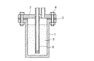
図4は、このような処理材を充填した容器の一例を示すものであり、フランジ部を有するケース1、フランジ部と流体の出入り口を有する蓋2、シート状弾性体3、締結用ボルト4、粉粒状処理材5、導管6で構成される。導管6については蓋2の内側に圧入、溶接、接着等の方法で取り付けられており、先端部分には充填された粉粒状処理材が流出しないよう、メッシュ等が配せられている。
図5は、比較的小型な容器の一例を示すものであり、線状弾性体7を装着する取付溝21を有するケース1、ケース1との螺合部と流体の出入り口を有する蓋2、線状弾性体7、粉粒状処理材5、導管6で構成される。流体は、流体入り口10より入り、粉粒状処理材5内を通過して、容器底部で反転し、導管6を通り、流体出口11より流出する。
【0004】
【発明が解決しようとする課題】
図4に示したような従来の容器に於いては、シート状弾性体3を用いて封止を行うためフランジ部が必要となるので、小型化の妨げとなり、ケース1や蓋2を樹脂で成形しても軽量化を図ることが難しいという不具合点があった。
【0005】
また図5に示したような、線状弾性体7を用いて流体の封止を行った容器の場合には、以下のような問題点があった。
まず、容器の加圧、除圧により線状弾性体7の位置が僅かに移動し、その動きに伴い粉粒状処理材5が、線状弾性体7とケース1との間に入り込み、線状弾性体7及びケース1が傷つく事により、短期間で封止機能が低下することがあった。
さらにこの容器に於いては、別の場所へ移動する際に振動や姿勢の変動により、粉粒状処理材5と線状弾性体7が接触し、粉粒状処理材5の一部が線状弾性体7とケース1との間に付着した状態で残り、容器を使用すると、線状弾性体7及びケース1が傷つく事により、短期間で封止機能が低下することがあった。
同時にこの容器に於いては、使用途中に落下等の強い衝撃を受けた場合、粉粒状処理材5の一部が線状弾性体7とケース1との間に入り込み、容器を使用継続すると、線状弾性体7及びケース1が傷つく事により、短期間で封止機能が低下することがあった。
【0006】
本発明は、前記問題点に鑑み、流体の処理材を充填した容器において、流体封止性能を長期間維持できるとともに、小型化、軽量化の要請を満たす容器を提供することを目的とする。
【0007】
【課題を解決するための手段】
本発明の容器は、粉粒状の処理材を収納するためのケースと、該ケース内に挿入される円筒部が形成され、該ケースの開口を塞ぐ蓋とからなる容器であり、該蓋には流体導入口および流体導出口が設けられ、該容器内に加圧した流体を流通させる容器であって、前記ケースおよび前記蓋の円筒部の間に設けられ、前記ケースと前記蓋に密着する線状弾性体を少なくとも2本と、前記蓋に被せて、前記ケースに固定するナットと、を備えたことを特徴としている。前記処理材は、流体と接触して吸着、濾過、反応のいずれかを行う処理材でもよく、さらにこれらの処理材に多孔質中空糸膜モジュールを組み合わせてもよい。
本発明の浄水器カートリッジは、前記容器に、粉粒状の処理材が収納されたことを特徴とする。
【0008】
【発明の実施の形態】
以下図面に基づいて、本発明を説明する。図1ないし図3は、各々本発明の容器の例を示したものであるが、本発明はこれらの例に制限されるものではない。
【0009】
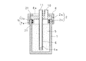
図1に示した容器は、上方に開口する有底筒状のケース1と、流体導入口10、流体導出口11を有し、ケース1の開口を塞ぐ蓋2と、ケース1に対し、蓋2を固定する袋状ナット8と、ケース1と蓋2とを封止する線状弾性体7と、ケース内に充填された粉粒状処理材5と、流体を外部へ導く導管6とから概略構成される。
蓋2は、天面部2aとその下面に形成されたケース1に挿入される円筒部2bからなり、円筒部2bの外周面には、線状弾性体7を装着するための取付溝21が全周に亙って少なくとも2本形成され、天面部2aには流体導入口10、流体導出口11が上方に突出するように穿設されている。
そして、導管6が蓋2の流体導出口11内側に圧入され、溶接、接着等の方法で蓋2に固定されている。導管6の先端部分には充填された粉粒状処理材5が流出しないよう、メッシュ状あるいは多孔質状の先端部材6aが配せられている。
【0010】
袋状ナット8とケース1には、互いに螺合するネジが形成されている。そして、蓋2の円筒部2bがケース1に挿入された状態で、孔8aに流体導入口10と流体導出口11が挿入され、かつ袋状ナット8が蓋2の天面部2aの外縁部を挟みこむようにして、袋状ナット8とケース1とが螺合するようになっている。袋状ナットは、加圧状態で、蓋2がケース1から抜けることを防止するために設けられたものである。
前記ケース1、蓋2、および袋状ナット8の材質は、使用時の耐圧性、製造時の成形性を考慮して、ABS樹脂、ポリプロピレン樹脂、ポリスルホン樹脂、ポリアセタール樹脂、ポリカーボネート樹脂、ポリアミド樹脂等のプラスチックが好ましく、更に強度を持たせたい場合、ステンレス金属を用いることが好ましい。
ケース1と袋状ナット8は、螺合に代えて、バイヨネット等で連結することもできる。
【0011】
本発明の容器は、ケース1および蓋2の一方に設けられ、他方を付勢してケース1と蓋2に密着する線状弾性体7を少なくとも2本備えている。
線状弾性体7は、蓋2に形成された取付溝21の全周にわたる長さを有し、かつ取付溝21内に圧入される幅を有する直線状、あるいは環状のゴム弾性体であればよく、その材質は、ニトリルゴム、シリコンゴム、フッ素ゴム、スチレンブタジエンゴム、クロロプレンゴム、エチレンプロピレンゴム、ブチルゴム等の合成ゴムを用いることが好ましい。
この線状弾性体7は、ケース1に蓋2を被せる前に、取付溝21内に圧入される。線状弾性体7が直線状の場合は、両端部が突合せになるように取付溝21に圧入する。また線状弾性体7が環状の場合は、線状弾性体7に引張力を加えて延伸させ、蓋2の下方から取付溝21内に嵌め合わせる。
いずれの線状弾性体7の場合も、取付溝21の奥に線状弾性体7が当接するまで圧入した状態で、線状弾性体7が、蓋2の円筒部2bの外周面より外側に若干突出するような太さを有している。このような線状弾性体7は、線状弾性体7が取り付けられた蓋2を挟んで前記袋状ナット8をケース1に対して締め付けることにより、線状弾性体7がケース1に押圧され、付勢した状態でケース1との面接触を維持して、ケース1と蓋2に密着するので、ケース1と蓋2との連結状態を確実にするとともに、容器の使用時における加圧流体の漏れを防止することができる。
なお、図1に示した例では、線状弾性体7は蓋2の円筒部2bの外周面に取付溝21を形成したが、これに代えてケース1の内周面側に取付溝を形成しても良い。この場合、線状弾性体7は、ケース1に蓋2を被せる前に、ケース1の取付溝内に圧入される。線状弾性体7が直線状の場合は、両端部が突合せになるように取付溝に圧入する。この状態で、前述の方法と同様に、蓋2の円筒部2bをケース1の開口部に挿入して袋状ナット8を被せて締め付ければ、線状弾性体7が蓋2の円筒部2bに押圧され、付勢した状態で蓋2の円筒部2bとの面接触を維持してケース1と蓋2に密着するので、ケース1と蓋2との連結状態が確実となり、容器の使用時における加圧流体の漏れを防止することができる。
さらに、蓋2とケース1の両方に取付溝を形成し、各々前述の方法で線状弾性体7を装着することもできる。
あるいは、環状の線状弾性体7を用いれば、取付溝を全く形成しなくても、蓋2への装着が可能である。すなわち、線状弾性体7に引張力を加えて延伸させ、蓋2の下方から蓋2の円筒部2bに装着すればよい。
【0012】
ケース1に充填される処理材としては、容器の使用目的に応じて、流体に含まれる有害成分や臭気成分等の吸着、流体中の濁質の濾過、流体含有成分との反応を行う周知の処理材を用いることができ、例えば、粉末活性炭、粒状活性炭、イオン交換樹脂等が挙げられる。 例えば、浄水器として使用する場合は、亜硫酸カルシウム、粉粒状活性炭、アスコルビン酸などの脱塩素処理剤、イオン交換樹脂などの処理材が用いられる。これらは、単独で使用しても2種類以上を併用してもよい。
また本発明において、流体は、液体、気体のいずれでもよく、その種類は限定されない。
【0013】
この容器に、流体を通すときには、流体は加圧された状態で、流体導入口10より容器内に導入され、粉粒状処理材5内を下方向に通過して、容器底部で反転し、導管6を上方向に通り、流体導出口11より所定の処理が施された流体が排出される。
ここで、加圧された流体が導入されて容器内部の圧力が高まった場合、袋状ナット8とケース1は材料の弾性により変形し、これに伴って粉粒状処理材5に近い側(以下、内側という)の線状弾性体7aの付勢力が低下する。この結果、線状弾性体7とケース1と間に、粉粒状処理材5の一部が侵入する。その後、容器内部が除圧されると、内側の線状弾性体7aは、侵入した粉粒状処理材をケース1との間に挟んだまま元の位置に戻る。この操作の繰り返しにより、ケース1と内側の線状弾性体7aとの間への粉粒状処理材5の侵入が進み、内側の線状弾性体7aの流体封止性能は低下する。しかしこの内側の線状弾性体7aは、粉粒状処理材の侵入をその場に止め、その上方には粉粒状処理材は侵入しない。このため、粉粒状処理材に遠い側(以下、外側という)の線状弾性体7bは、その十分な封止性能を、長期間に亙り維持することが可能となる。
【0014】
このように、本発明の容器において、内側の線状弾性体7aは、ケース1と内側の線状弾性体7aとの間に侵入する処理材を捕捉して、外側の線状弾性体7bを保護するためのものであるので、処理材をその場に止めることができれば良く、完全な流体封止機能は要求されない。これに対し、外側の線状弾性体7bは、流体の封止を確実にする機能が必要であるから、強いゴム弾性を発揮するようにその形状や材質が決められる。
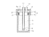
図2に、内側の線状弾性体として、ダストシールを使用した例を示す。図1と同様の部材には、同一符号を付して説明を省略する。
ダストシール9は、V型、X型等の断面を有する環状の弾性体であって、封止状態でも、取付溝21内に空間を保持するものである。ダストシールの材質としては、ニトリルゴム、シリコンゴム、フッ素ゴム、スチレンブタジエンゴム、クロロプレンゴム、エチレンプロピレンゴム、ブチルゴム等の合成ゴムを用いる。ダストシール9は、蓋2の円筒部2bに形成された2本の取付溝21のうち、内側の取付溝21に装着する。そして、より封止能力の高い外側の線状弾性体7bはダストシール9より外側の取付溝21に装着する。ダストシール9は、外側の線状弾性体7bのような流体封止能力は無いが、粉粒状処理材5の侵入をその場に止めることができるので、外側の線状弾性体7bは十分な封止性能を、長期間に亙り維持することが可能となる。さらに、図1に示した内側の線状弾性体を使用する場合に比べて、ダストシール9は、封止状態において取付溝21との間に空間を保持しているので、ダストシール9自身を傷つけずに多くの粉粒状処理材を捕捉できるという利点がある。
図2に示した容器に流体を通すときには、流体は加圧された状態で、流体導入口10より容器内に導入され、粉粒状処理材5内を下方向に通過して、容器底部で反転し、導管6を上方向に通り、流体導出口11より所定の処理が施された流体が流出する。
【0015】
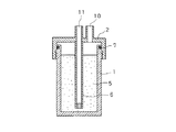
図3は、浄水器カートリッジとしての実施例を示す。図1と同様の部材には、同一符号を付して説明を省略する。
この浄水器カートリッジは、筒状のケース1と、ケース1の一方の開口を塞ぐ底蓋14と、流体導入口10と流体導出口11を有し、かつケース1の他方の開口を塞ぐ上蓋2と、ケース1に対し、底蓋14と上蓋2を固定する袋状ナット8と、ケース1と底蓋14ならびにケース1と上蓋2の封止を確実にするための線状弾性体7と、ケース1内に収納された多孔質中空糸膜モジュール13と、多孔質中空糸膜モジュール13の周囲に充填された粉粒状の水処理材12と、この水処理材12の下部に配された目皿15から構成される。
この多孔質中空糸膜モジュール13は、浄水器に一般的に用いられているものであれば特に制限されないが、例えばシリコーン系、ポリオレフィン系、ポリエステル系、ポリアミド系、ポリスルホン系、セルロース系、ポリウレタン系などの多孔質中空糸膜をポッティング剤により集束固定し、ハウジング内に収納されたものが用いられる(特開平5−261253号公報、特開平6−340号公報、特開平6−342号公報等を参照)。図示した多孔質中空糸膜モジュールは、多孔質中空糸膜の固定部側の端部が上蓋に設けられた流体導出口11に連通するように挿入され、かつ他方の端部が底蓋14から離間されるようにして、蓋2に着脱自在あるいは一体化されて装着されている。
【0016】
目皿15は、粉粒状処理材5が、多孔質中空糸膜モジュール13内部に侵入するのを防止するために設けられるもので、多孔質中空糸膜モジュール13が所定位置に装着された状態で底蓋14から離間してケース1の内側に嵌め合わされるように、中央にモジュール挿入孔15aを有するドーナツ形状をなす多孔質体、例えば多孔質燒結フィルターなどからなる。
この容器に、流体を通すときには、流体は加圧された状態で、流体導入口10より容器内に導入され、水処理材12内を下方向に通過した後、目皿15を通過して、目皿15の下方に設けられた空間16に達し、ついで空間16で反転して多孔質中空糸膜モジュール13内に入り、多孔質中空糸膜モジュール13で濾過され、上部の流体導出口11より所定の処理が施された流体が排出される。
なお、本発明において、線状弾性体7は、少なくとも2本あればよいが、より確実な封止を目的として、3本以上の線状弾性体を使用することもできる。
【0017】
【発明の効果】
以上説明したように、本発明の容器は、粉粒状の処理材を収納するためのケースと、該ケース内に挿入される円筒部が形成され、該ケースの開口を塞ぐ蓋とからなる容器であり、該蓋には流体導入口および流体導出口が設けられ、該容器内に加圧した流体を流通させる容器であって、前記ケースおよび前記蓋の円筒部の間に設けられ、前記ケースと前記蓋に密着する線状弾性体を少なくとも2本と、前記蓋に被せて、前記ケースに固定するナットと、を備えた容器である。本発明の容器では、容器の加圧および除圧や、落下等の強い衝撃により、粉粒状処理材がケースと内側の線状弾性体との間に入り込んだ場合や、振動、容器の向きの変動、落下などにより、粉粒状処理材と線状弾性体が接触し粉粒状処理材の一部が、ケースと内側の線状弾性体との間に付着した状態で残った場合でも、内側に配される線状弾性体が侵入する処理材を捕捉して、外側の弾性体を保護し、外側に配される線状弾性体が、流体の封止を確実とする。このようにして、本発明の容器では、線状弾性体を少なくとも2本用いて確実な流体封止を長期間維持することができるので、ケースと蓋との封止構造を単純化できる。これにより、ケースと蓋とを螺合等による簡単な組み付けにより容易に作製することができ、小型軽量化が達成できる。したがって、特に小型軽量化が求められる家庭用の飲料水の製造、空気の浄化などを目的とした使用に好適である。更に粉粒状処理材が充填された状態での流体封止性能が飛躍的に向上し、長期間に亙り封止性能を維持可能であり、使用者に多大な経済性、利便性を提供するものである。したがって、流体を対象とした吸着、濾過、反応のいずれかを目的とした用途に広く適用可能である。
【図面の簡単な説明】
【図1】 本発明の容器の実施例断面図である。
【図2】 本発明の容器の実施例断面図である。
【図3】 本発明の容器の実施例断面図である。
【図4】 従来の容器断面図である。
【図5】 従来の容器断面図である。
【符号の説明】
1 ケース
2 蓋
5 粉粒状処理材
7 線状弾性体
12 水処理材
13 多孔質中空糸膜モジュール[0001]
BACKGROUND OF THE INVENTION
The present invention relates to a container that includes a case in which a fluid processing material is stored and a lid that closes the opening of the case, and distributes pressurized fluid in the case.
[0002]
[Prior art]
Conventionally, powders such as powdered activated carbon, granular activated carbon, and ion exchange resin have been used to perform adsorption, filtration, reaction, etc. for liquids such as tap water, well water, and industrial wastewater, and gases such as air, oxygen, and nitrogen. A granular processing material is used. This granular processing material is filled in a cylindrical case or a closed cup-shaped case at one end, and the case is pressurized in the case with the opening of the case sealed with a lid having a fluid entrance. Fluid is circulated. At this time, a sheet-like or linear elastic body may be used as a packing between the case and the lid in order to prevent the powdery processing material inside the container from flowing out and fluid leakage.
[0003]
FIG. 4 shows an example of a container filled with such a treatment material. The
FIG. 5 shows an example of a relatively small container, which includes a
[0004]
[Problems to be solved by the invention]
In the conventional container as shown in FIG. 4, since the flange portion is necessary for sealing with the sheet-like
[0005]
Further, in the case of a container in which fluid is sealed using the linear
First, the position of the linear
Further, in this container, the
At the same time, in this container, when a strong impact such as dropping is received during use, a part of the
[0006]
In view of the above problems, an object of the present invention is to provide a container that can maintain fluid sealing performance for a long time in a container filled with a fluid treatment material, and that satisfies the demands for miniaturization and weight reduction.
[0007]
[Means for Solving the Problems]
The container of the present invention includes a case for housing the particulate treatment member, the cylindrical portion to be inserted in the casing is formed, a container comprising a lid for closing the opening of the case, the lid A container provided with a fluid introduction port and a fluid outlet port , through which a pressurized fluid is circulated, and is provided between the case and the cylindrical portion of the lid, and is in contact with the case and the lid It comprises at least two shaped elastic bodies and a nut that covers the lid and is fixed to the case. The treatment material may be a treatment material that performs any of adsorption, filtration, and reaction in contact with a fluid, and a porous hollow fiber membrane module may be combined with these treatment materials.
The water purifier cartridge of the present invention is characterized in that a powdery treatment material is accommodated in the container.
[0008]
DETAILED DESCRIPTION OF THE INVENTION
The present invention will be described below with reference to the drawings. 1 to 3 show examples of the container of the present invention, but the present invention is not limited to these examples.
[0009]
The container shown in FIG. 1 has a bottomed
The
And the conduit |
[0010]
The bag-
The
The
[0011]
The container of the present invention includes at least two linear
The linear
The linear
In any linear
In the example shown in FIG. 1, the linear
Furthermore, it is also possible to form attachment grooves in both the
Alternatively, if the annular linear
[0012]
The treatment material filled in the
In the present invention, the fluid may be either liquid or gas, and the type is not limited.
[0013]
When the fluid is passed through the container, the fluid is introduced into the container through the
Here, when the pressurized fluid is introduced and the pressure inside the container is increased, the bag-shaped
[0014]
Thus, in the container of the present invention, the inner linear elastic body 7a captures the treatment material that enters between the
FIG. 2 shows an example in which a dust seal is used as the inner linear elastic body. The same members as those in FIG. 1 are denoted by the same reference numerals and description thereof is omitted.
The
When the fluid is passed through the container shown in FIG. 2, the fluid is introduced into the container through the
[0015]
FIG. 3 shows an embodiment as a water purifier cartridge. The same members as those in FIG. 1 are denoted by the same reference numerals and description thereof is omitted.
This water purifier cartridge has a
The porous hollow
[0016]
The
When passing the fluid through the container, the fluid is introduced into the container through the
In the present invention, at least two linear
[0017]
【The invention's effect】
As described above, the container of the present invention is a container including a case for storing a powdery processing material and a lid that is formed with a cylindrical portion inserted into the case and closes the opening of the case. The lid is provided with a fluid inlet and a fluid outlet, and is a container for circulating a pressurized fluid in the container, and is provided between the case and the cylindrical portion of the lid; The container includes at least two linear elastic bodies that are in close contact with the lid, and a nut that covers the lid and is fixed to the case. In the container of the present invention, when the granular processing material gets in between the case and the inner linear elastic body due to strong pressure such as pressurization and depressurization of the container or dropping, or vibration, the direction of the container Even if the granular processing material comes into contact with the linear elastic body due to fluctuation, drop, etc., and part of the granular processing material remains attached between the case and the inner linear elastic body, The processing material which the linear elastic body arranged invades captures and protects the outer elastic body, and the linear elastic body arranged outside ensures the sealing of the fluid. In this way, in the container of the present invention, reliable fluid sealing can be maintained for a long time by using at least two linear elastic bodies, so that the sealing structure between the case and the lid can be simplified. Accordingly, the case and the lid can be easily manufactured by simple assembly such as screwing, and a reduction in size and weight can be achieved. Therefore, it is suitable for use for the purpose of producing drinking water for home use and purifying air, which are particularly required to be small and light. Furthermore, the fluid sealing performance in the state filled with the granular processing material is dramatically improved, and the sealing performance can be maintained over a long period of time, providing the user with great economic efficiency and convenience. It is. Therefore, the present invention can be widely applied to applications intended for any one of adsorption, filtration, and reaction targeting fluids.
[Brief description of the drawings]
1 is a cross-sectional view of an embodiment of the container of the present invention.
FIG. 2 is a cross-sectional view of an embodiment of the container of the present invention.
FIG. 3 is a cross-sectional view of an embodiment of the container of the present invention.
FIG. 4 is a cross-sectional view of a conventional container.
FIG. 5 is a cross-sectional view of a conventional container.
[Explanation of symbols]
DESCRIPTION OF
Claims (4)
Priority Applications (1)
| Application Number | Priority Date | Filing Date | Title |
|---|---|---|---|
| JP13930799A JP4174134B2 (en) | 1999-05-19 | 1999-05-19 | Container and water purifier cartridge |
Applications Claiming Priority (1)
| Application Number | Priority Date | Filing Date | Title |
|---|---|---|---|
| JP13930799A JP4174134B2 (en) | 1999-05-19 | 1999-05-19 | Container and water purifier cartridge |
Publications (3)
| Publication Number | Publication Date |
|---|---|
| JP2000325952A JP2000325952A (en) | 2000-11-28 |
| JP2000325952A5 JP2000325952A5 (en) | 2006-07-06 |
| JP4174134B2 true JP4174134B2 (en) | 2008-10-29 |
Family
ID=15242259
Family Applications (1)
| Application Number | Title | Priority Date | Filing Date |
|---|---|---|---|
| JP13930799A Expired - Fee Related JP4174134B2 (en) | 1999-05-19 | 1999-05-19 | Container and water purifier cartridge |
Country Status (1)
| Country | Link |
|---|---|
| JP (1) | JP4174134B2 (en) |
Families Citing this family (7)
| Publication number | Priority date | Publication date | Assignee | Title |
|---|---|---|---|---|
| KR100894094B1 (en) | 2007-05-11 | 2009-04-20 | 한국정수공업 주식회사 | Retainer for Modules of cylindrical electrodeionization apparatus |
| JP2011092806A (en) * | 2009-10-27 | 2011-05-12 | Panasonic Electric Works Co Ltd | Water treatment device |
| JP5373138B2 (en) * | 2012-03-16 | 2013-12-18 | シャープ株式会社 | Water treatment apparatus and water purifier provided with the same |
| JP6225134B2 (en) * | 2015-03-03 | 2017-11-01 | トクラス株式会社 | Water purification cartridge and faucet |
| JP6186021B2 (en) * | 2016-01-22 | 2017-08-23 | トクラス株式会社 | Water purification cartridge and faucet |
| JP6694378B2 (en) * | 2016-12-26 | 2020-05-13 | 本田技研工業株式会社 | Pure water purification device for fuel cell power generation system |
| CN115584289B (en) * | 2022-10-28 | 2023-04-07 | 东营兴盛石油化工有限责任公司 | Oil well associated gas separation device and treatment method |
-
1999
- 1999-05-19 JP JP13930799A patent/JP4174134B2/en not_active Expired - Fee Related
Also Published As
| Publication number | Publication date |
|---|---|
| JP2000325952A (en) | 2000-11-28 |
Similar Documents
| Publication | Publication Date | Title |
|---|---|---|
| US6004460A (en) | Portable water filtration bottle | |
| CA2350292C (en) | Water purifying apparatus | |
| AU2005247861B2 (en) | Filter element with off-axis end cap | |
| US4911840A (en) | Water conditioning apparatus | |
| KR20110102423A (en) | Fluid filter assembly including seal | |
| JP4174134B2 (en) | Container and water purifier cartridge | |
| US10961128B2 (en) | Water processing device | |
| JP5017912B2 (en) | Water purifier cartridge and water purifier | |
| JP2016163876A (en) | Water purification cartridge | |
| KR100614894B1 (en) | Cartridge for water purifier | |
| JP5090593B2 (en) | Water purification cartridge | |
| JP2009507635A (en) | Purification filter | |
| CN108430930B (en) | Water purification cartridge | |
| JP4176312B2 (en) | Activated carbon pack for water purifier | |
| JP6447239B2 (en) | Water purification cartridge | |
| CA2457240C (en) | Improved sealing mechanism and filter cartridge with improved sealing mechanism | |
| JP2000325952A5 (en) | ||
| JP3775150B2 (en) | Water purification cartridge | |
| JPH0632175Y2 (en) | Hollow fiber membrane module cartridge | |
| JP3700669B2 (en) | Water purifier cartridge | |
| KR101957496B1 (en) | Faucet filter, filter assembly and water treatment apparatus including same | |
| JPH0238249B2 (en) | ||
| JP4096827B2 (en) | Water purification cartridge | |
| JP5629677B2 (en) | Portable water purifier | |
| CN110753811B (en) | Anti-leakage check valve |
Legal Events
| Date | Code | Title | Description |
|---|---|---|---|
| A521 | Written amendment |
Free format text: JAPANESE INTERMEDIATE CODE: A523 Effective date: 20060519 |
|
| A621 | Written request for application examination |
Free format text: JAPANESE INTERMEDIATE CODE: A621 Effective date: 20060519 |
|
| A521 | Written amendment |
Free format text: JAPANESE INTERMEDIATE CODE: A523 Effective date: 20060519 |
|
| A977 | Report on retrieval |
Free format text: JAPANESE INTERMEDIATE CODE: A971007 Effective date: 20080130 |
|
| A131 | Notification of reasons for refusal |
Free format text: JAPANESE INTERMEDIATE CODE: A131 Effective date: 20080212 |
|
| A521 | Written amendment |
Free format text: JAPANESE INTERMEDIATE CODE: A523 Effective date: 20080410 |
|
| A131 | Notification of reasons for refusal |
Free format text: JAPANESE INTERMEDIATE CODE: A131 Effective date: 20080520 |
|
| A521 | Written amendment |
Free format text: JAPANESE INTERMEDIATE CODE: A523 Effective date: 20080709 |
|
| TRDD | Decision of grant or rejection written | ||
| A01 | Written decision to grant a patent or to grant a registration (utility model) |
Free format text: JAPANESE INTERMEDIATE CODE: A01 Effective date: 20080805 |
|
| A01 | Written decision to grant a patent or to grant a registration (utility model) |
Free format text: JAPANESE INTERMEDIATE CODE: A01 |
|
| A61 | First payment of annual fees (during grant procedure) |
Free format text: JAPANESE INTERMEDIATE CODE: A61 Effective date: 20080818 |
|
| FPAY | Renewal fee payment (event date is renewal date of database) |
Free format text: PAYMENT UNTIL: 20110822 Year of fee payment: 3 |
|
| FPAY | Renewal fee payment (event date is renewal date of database) |
Free format text: PAYMENT UNTIL: 20120822 Year of fee payment: 4 |
|
| FPAY | Renewal fee payment (event date is renewal date of database) |
Free format text: PAYMENT UNTIL: 20120822 Year of fee payment: 4 |
|
| FPAY | Renewal fee payment (event date is renewal date of database) |
Free format text: PAYMENT UNTIL: 20120822 Year of fee payment: 4 |
|
| FPAY | Renewal fee payment (event date is renewal date of database) |
Free format text: PAYMENT UNTIL: 20130822 Year of fee payment: 5 |
|
| R250 | Receipt of annual fees |
Free format text: JAPANESE INTERMEDIATE CODE: R250 |
|
| R250 | Receipt of annual fees |
Free format text: JAPANESE INTERMEDIATE CODE: R250 |
|
| R250 | Receipt of annual fees |
Free format text: JAPANESE INTERMEDIATE CODE: R250 |
|
| R250 | Receipt of annual fees |
Free format text: JAPANESE INTERMEDIATE CODE: R250 |
|
| LAPS | Cancellation because of no payment of annual fees |