JP4172867B2 - Mouse with wheel - Google Patents
Mouse with wheel Download PDFInfo
- Publication number
- JP4172867B2 JP4172867B2 JP04274199A JP4274199A JP4172867B2 JP 4172867 B2 JP4172867 B2 JP 4172867B2 JP 04274199 A JP04274199 A JP 04274199A JP 4274199 A JP4274199 A JP 4274199A JP 4172867 B2 JP4172867 B2 JP 4172867B2
- Authority
- JP
- Japan
- Prior art keywords
- wheel
- mouse
- switch
- rotating body
- polygonal
- Prior art date
- Legal status (The legal status is an assumption and is not a legal conclusion. Google has not performed a legal analysis and makes no representation as to the accuracy of the status listed.)
- Expired - Lifetime
Links
Images


Classifications
-
- G—PHYSICS
- G06—COMPUTING; CALCULATING OR COUNTING
- G06F—ELECTRIC DIGITAL DATA PROCESSING
- G06F3/00—Input arrangements for transferring data to be processed into a form capable of being handled by the computer; Output arrangements for transferring data from processing unit to output unit, e.g. interface arrangements
- G06F3/01—Input arrangements or combined input and output arrangements for interaction between user and computer
- G06F3/03—Arrangements for converting the position or the displacement of a member into a coded form
- G06F3/033—Pointing devices displaced or positioned by the user, e.g. mice, trackballs, pens or joysticks; Accessories therefor
- G06F3/038—Control and interface arrangements therefor, e.g. drivers or device-embedded control circuitry
-
- G—PHYSICS
- G06—COMPUTING; CALCULATING OR COUNTING
- G06F—ELECTRIC DIGITAL DATA PROCESSING
- G06F3/00—Input arrangements for transferring data to be processed into a form capable of being handled by the computer; Output arrangements for transferring data from processing unit to output unit, e.g. interface arrangements
- G06F3/01—Input arrangements or combined input and output arrangements for interaction between user and computer
- G06F3/03—Arrangements for converting the position or the displacement of a member into a coded form
- G06F3/0304—Detection arrangements using opto-electronic means
- G06F3/0312—Detection arrangements using opto-electronic means for tracking the rotation of a spherical or circular member, e.g. optical rotary encoders used in mice or trackballs using a tracking ball or in mouse scroll wheels
-
- G—PHYSICS
- G06—COMPUTING; CALCULATING OR COUNTING
- G06F—ELECTRIC DIGITAL DATA PROCESSING
- G06F3/00—Input arrangements for transferring data to be processed into a form capable of being handled by the computer; Output arrangements for transferring data from processing unit to output unit, e.g. interface arrangements
- G06F3/01—Input arrangements or combined input and output arrangements for interaction between user and computer
- G06F3/03—Arrangements for converting the position or the displacement of a member into a coded form
- G06F3/033—Pointing devices displaced or positioned by the user, e.g. mice, trackballs, pens or joysticks; Accessories therefor
- G06F3/0338—Pointing devices displaced or positioned by the user, e.g. mice, trackballs, pens or joysticks; Accessories therefor with detection of limited linear or angular displacement of an operating part of the device from a neutral position, e.g. isotonic or isometric joysticks
-
- G—PHYSICS
- G06—COMPUTING; CALCULATING OR COUNTING
- G06F—ELECTRIC DIGITAL DATA PROCESSING
- G06F3/00—Input arrangements for transferring data to be processed into a form capable of being handled by the computer; Output arrangements for transferring data from processing unit to output unit, e.g. interface arrangements
- G06F3/01—Input arrangements or combined input and output arrangements for interaction between user and computer
- G06F3/03—Arrangements for converting the position or the displacement of a member into a coded form
- G06F3/033—Pointing devices displaced or positioned by the user, e.g. mice, trackballs, pens or joysticks; Accessories therefor
- G06F3/0354—Pointing devices displaced or positioned by the user, e.g. mice, trackballs, pens or joysticks; Accessories therefor with detection of 2D relative movements between the device, or an operating part thereof, and a plane or surface, e.g. 2D mice, trackballs, pens or pucks
- G06F3/03543—Mice or pucks
-
- G—PHYSICS
- G06—COMPUTING; CALCULATING OR COUNTING
- G06F—ELECTRIC DIGITAL DATA PROCESSING
- G06F3/00—Input arrangements for transferring data to be processed into a form capable of being handled by the computer; Output arrangements for transferring data from processing unit to output unit, e.g. interface arrangements
- G06F3/01—Input arrangements or combined input and output arrangements for interaction between user and computer
- G06F3/03—Arrangements for converting the position or the displacement of a member into a coded form
- G06F3/033—Pointing devices displaced or positioned by the user, e.g. mice, trackballs, pens or joysticks; Accessories therefor
- G06F3/0362—Pointing devices displaced or positioned by the user, e.g. mice, trackballs, pens or joysticks; Accessories therefor with detection of 1D translations or rotations of an operating part of the device, e.g. scroll wheels, sliders, knobs, rollers or belts
-
- G—PHYSICS
- G06—COMPUTING; CALCULATING OR COUNTING
- G06F—ELECTRIC DIGITAL DATA PROCESSING
- G06F3/00—Input arrangements for transferring data to be processed into a form capable of being handled by the computer; Output arrangements for transferring data from processing unit to output unit, e.g. interface arrangements
- G06F3/01—Input arrangements or combined input and output arrangements for interaction between user and computer
- G06F3/03—Arrangements for converting the position or the displacement of a member into a coded form
- G06F3/033—Pointing devices displaced or positioned by the user, e.g. mice, trackballs, pens or joysticks; Accessories therefor
- G06F3/038—Control and interface arrangements therefor, e.g. drivers or device-embedded control circuitry
- G06F3/0383—Signal control means within the pointing device
Description
【0001】
【発明の属する技術分野】
本発明は、表示装置のポインタ操作を容易にする座標入力装置に関する。
【0002】
【従来の技術】
近年PCの操作性を向上するためにGUI(Graphical User Interface)が採用されているが、ディスプレイ画面上のアイコン等を指示するための座標入力装置としてマウスやポインティングデバイス等が多用されている。
現在一般的に使用されているマウスは、ユーザによるX軸およびY軸方向の操作量および2つのクリックスイッチの操作を出力する形式のものが大半である。
【0003】
図1は従来のマウスの原理図である。ユーザによるマウスの操作によってボール10が回転する。このボール10に対して相互に直交するX軸およびY軸に沿って、X方向シャフト11およびY方向シャフト12がボール10に接触するように配置されている。ボール10とX方向シャフト11およびY方向シャフト12との接触を維持するために、X軸およびY軸に対して45度の方向に押さえローラ15が設置されている。
【0004】
X方向シャフト11およびY方向シャフト12の先端には、X軸用ロータリエンコーダ25およびY軸用ロータリエンコーダ26が取り付けられており、ボール10の回転方向および回転量をX軸方向とY軸方向とに分けて検出する。X軸用ロータリエンコーダ25はX軸スリット円盤13、X軸発光素子16およびX軸受光素子17を、Y軸用ロータリエンコーダ26はY軸スリット円盤14、Y軸発光素子18およびY軸受光素子19を、それぞれ備える。X軸スリット円盤13およびY軸スリット円盤14にはそれぞれ一定角度ごとにスリットが設けられており、X軸発光素子16およびY軸発光素子18から発光された光は、それぞれX軸スリット円盤13およびY軸スリット円盤14を通過し、X軸受光素子17およびY軸受光素子19で受光される。
【0005】
図2および3は、マウス20の移動方向および移動量、すなわちX方向シャフト11およびY方向シャフト12の回転方向および回転量のロータリエンコーダによる検出について説明する図である。ここで説明を簡単にするため、図2および3の発光素子41、受光素子42、スリット円盤43は、それぞれ図1のX軸発光素子16およびY軸発光素子18、X軸受光素子17およびY軸受光素子19X軸スリット円盤13およびY軸スリット円盤14に、それぞれ対応するものとする。すなわち、図2および3でX方向、Y方向のどちらの回転に関しても説明できる。
【0006】
図2に示すように、受光素子42内には、それぞれ2つの光学受光素子、例えばフォトコンダクタ44,45が並んで備えられている。図3(a) ,(b) に示すように、フォトコンダクタ44,45により検出され電気信号に変換されたパルスをそれぞれパルスA、パルスBとすると、スリット円盤43の回転方向によってパルスAとパルスBとの位相関係が変わるので、スリット円盤43の回転方向を検出できる。さらに、パルスAあるいはパルスBをカウントすることによってスリット円盤43の回転量を検出できる。
【0007】
図4は従来のマウスの4面図であり、図4(a) は上面図を、図4(b) は前面図を、図4(c) は側面図を、図4(d) は後面図を示す。従来のマウス20は、ロアケース21とアッパーケース22とを嵌合させた後、アッパーケース22の前方にクリックスイッチSW1 ,SW2 が組み込まれたキートップ23を差し込みアッパーケース22に嵌合させる構造となっており、ケーブル24を介してホストに接続される。
【0008】
図5は従来のマウスの回路構成図である。X軸用ロータリエンコーダ25およびY軸用ロータリエンコーダ26はマウス20に内蔵される制御IC31内のボール回転検出部32に、左クリックスイッチSW1 および右クリックスイッチSW2 はマウスに内蔵される制御IC31内のスイッチ検出部33に、それぞれ接続されている。
制御IC31内のボール回転検出部32は、X軸用ロータリエンコーダ25およびY軸用ロータリエンコーダ26から出力から、マウス20の移動方向および移動量(以下、ボール座標データと呼ぶ)を検知し、ケーブル24を介してホストに伝送する。
【0009】
マウスの左クリックスイッチSW1 および右クリックスイッチSW2 には、メカニカルスイッチが使用されている。マイクロプロセッサで構成される制御IC31は、クリックスイッチが押下されたか否かを表す情報(以下、SW1 ,SW2 スイッチデータと呼ぶ)を、所定のフォーマットでホストに伝送する。
マウスの移動方向および移動量をX軸およびY軸方向に分解して検出し、この検出結果に応じて画面上に表示されているカーソルを移動させ、カーソルがアイコン上に重なったときにクリックスイッチを操作して、アイコンに対応する動作を行わせる。
【0010】
ホイール付きマウスは、上述のマウスにホイールをさらに備えたものである。これは、ホイールを操作することにより得られる回転を、例えばアプリケーション上の画面のスクロール機能として割り付けることができ、これにより近年複雑化しているアプリケーションソフトの操作を簡素化可能である。
図6は、従来のホイール付きマウスの4面図であり、図6(a) は上面図を、図6(b) は前面図を、図6(c) は側面図を、図6(d) は後面図を示す。ロアケース21とアッパーケース22とを嵌合させた後、アッパーケース22の前方にクリックスイッチSW1 ,SW2 が組み込まれたキートップ23を差し込みアッパーケース22に嵌合させる構造となっており、ケーブル24を介してホストに接続される。さらにキートップ23の中央には開口部61が設けられており、そこからホイール62の一部が外部に露出している。
【0011】
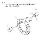
図7は従来のホイール付きマウスの回路構成図である。図3に示す従来のマウス回路に、ホイール用ロータリエンコーダ71およびホイール用回転検出部67が付加されている。
図8は従来のホイール付きマウスのホイール構造の斜視図である。ホイール62は、ホイール軸63を介して、ホイール用発光素子65、ホイール用受光素子66およびホイール用スリット円盤64を備えるホイール用ロータリエンコーダ71に結合されおり、図2および3を参照して説明した方法と同様にホイール62の回転方向および回転量が検出される。
【0012】
検出されたホイールの回転方向および回転量を表す情報(以下、ホイール回転データと呼ぶ) は、ボール座標データ、SW1 ,SW2 スイッチデータと共に所定のフォーマットでケーブル24を介してホストに伝送される。
このホイール回転データを、例えばアプリケーションソフトの画面上における垂直方向のスクロール機能として割り付けた場合、ホイール62をスクロールさせたい方向にユーザが指で操作することにより、カーソルを移動させずにアプリケーションソフト上の画面のスクロールが可能となる。
【0013】
【発明が解決しようとする課題】
上述のホイール付きマウスのホイールの操作は一方向にしか行えず、従って、例えばホイール回転データをアプリケーションソフトの画面上におけるスクロール機能として割り付けた場合、スクロールは一方向に限られる。この場合、他方向のスクロールには、スクロールバー操作が依然として必要である。
【0014】
さらに、マウスを移動させることができないような狭い場所にあっては、マウスの移動によってカーソルを操作することが難しい場合もある。このような場合には、マウスを移動させる第1の操作方法以外に、マウスを移動させずに第1の操作方法と同一の結果を得ることのできる第2の操作方法を備えることが望まれる。
【0015】
従って本発明の第1の目的は、上記課題に鑑み、常時は第1および第2の操作方法によりアプリケーションソフトウェアに対して2つの異なる操作を行うことが可能であると共に、第1の操作方法が不可能である場合には、第2の操作方法により第1の操作を行うことが可能な座標入力装置を提供することを目的とする。
【0016】
さらに本発明の第2の目的は、上記課題に鑑み、マウスを移動させる第1の操作方法以外に、マウスを移動させずに第1の操作方法と同一の結果を得ることのできる第2の操作方法に切換えが可能な切換えスイッチを有する座標入力装置を提供することにある。
【0017】
【課題を解決するための手段】
上記目的を達成するために、第1の発明では、ホイール付きマウスにおいて、ホイールの各辺のフレームを中心として回転可能な回転体を有する構造とする。本発明によれば、ホイールが回転することができる他に、回転体は多角形ホイールの回転に対して垂直の方向に回転することができる。
【0018】
また、上記目的を達成するために、第2の発明においては、座標入力装置は、ホストへ送るデータ出力フォーマットを切換えることができる切換えスイッチを備える。
本発明によれば、切換えスイッチによりデータ出力フォーマットを切換えることができる。
【0019】
【発明の実施の形態】
図9は本発明の第1の実施例による回転体付きホイールを有するマウスの斜視図である。また、図10は本発明の第1の実施例による回転体付きホイールを有するマウスの4面図であり、図10(a) は上面図を、図10(b) は前面図を、図10(c) は側面図を、図10(d) は後面図を示す。ロアケース21の後方部分はアッパーケース22によっておおわれている。またロアケース21の前方部分は、左クリックスイッチSW1 および右クリックスイッチSW2 が形成されたキートップ23によっておおわれている。さらにキートップ23の中央には開口部61が設けられており、そこから回転体付きホイール81の一部が外部に露出している。マウス80の操作信号はケーブル24を介してホストに伝送される。側面には切換えスイッチSW4 が備えられる。
【0020】
図11は本発明の第1の実施例によるマウスの回転体付きホイール構造の分解斜視図である。本実施例ではホイールは多角形の形状を有するが、特に形状は規定されない。回転体付きホイール81は、多角形ホイール82と、多角形ホイール82の各頂点と多角形ホイール82の中心部とを結合するスポーク83と、回転体84とを備え、ホイール軸63を中心に回転可能である。回転体84は、多角形ホイール82の各辺のフレームを中心に回転可能である。多角形ホイール82は本実施例では8角形の形状であるが、特に形状は規定されない。また、回転体84は本実施例では円筒形であるが、後述するように、特に形状は規定されない。
【0021】
多角形ホイール82の各辺のフレームのうち最上部にあるフレームに存在する回転体84は、マウス80のキートップ23の中央にある開口部61から外部に露出しており、ユーザは指で多角形ホイール82の回転および回転体84の回転が可能である。多角形ホイール82の中心部92は、ホイール支持部91で支持されており、回転体付きホイール81の下部にはスイッチSW3 が配置されている。多角形ホイール82の中心部92は、上下方向にスライドするスライド機構93を介してホイール支持部91に支持されている。本実施例ではスライド機構93はバネである。
【0022】
ユーザが指で開口部61から露出している回転体付きホイール81を下方向に押し込むと、多角形ホイール82がスライドし、回転体84がスイッチSW3 を押下する。スイッチSW3 には、いわゆる3つボタンマウスにおける中クリックスイッチの機能を割り当て可能である。
多角形ホイール82は、ホイール軸63を介して、ホイール用発光素子65、ホイール用受光素子66およびホイール用スリット円盤64を備えるホイール用ロータリエンコーダ71に結合されおり、図2および3を参照して説明した方法と同様に多角形ホイール82の回転方向および回転量が検出される。検出された多角形ホイールの回転方向および回転量を表すホイール回転データは、ケーブル24を介してホストに伝送される。
【0023】
多角形ホイール82の各辺のフレームのうち最上部にあるフレームに存在する回転体84は、球体シャフト85に接しており、この球体シャフト85は、回転体用発光素子87、回転体用受光素子88および回転体用スリット円盤86を備える回転体用ロータリエンコーダ72に結合されている。ユーザが指で回転体84に触れて回転させると、球体シャフト85はそれに応じて回転し回転体用スリット円盤86が回転するので、図2および3を参照して説明した方法と同様に回転体84の回転方向および回転量を検出できる。
【0024】
検出された円筒回転体84の回転方向および回転量を表す情報(以下、回転体回転データと呼ぶ)は、ボール座標データ、ホイール回転データ、SW1 ,SW2 ,SW3 スイッチデータと共に所定のフォーマットでケーブル24を介してホストに伝送される。
図12は本発明の第1の実施例による回路構成図であり、図7に示す従来のホイール付きマウスの回路に、回転体用ロータリエンコーダ72、回転体用回転検出部89、スイッチSW3 および切換えスイッチSW4 が付加されている。
【0025】
本発明によるマウス80では、回転体付きホイール81の操作量の見当をつけるため、回転体付きホイール81の多角形ホイール82および回転体84の手の指による回転操作の際、以下に示すようにクリック感を与えるようにする。
まず多角形ホイール82に関しては、ホイール支持部91に、少なくとも1つの弾性のある突起94を設け、多角形ホイール82の各スポーク間に引っかかるようにしてクリック感を与える。この突起94は、多角形ホイール82の位置を固定するのにも有効である。
【0026】
そして回転体84に関しては、回転体84の内部を凹凸構造95を設け、かつ多角形ホイール82の各辺のフレームに弾性のある突起96を設けることによりクリック感を与える。なお、本実施例では回転体84は円筒形であるが、回転体84がどのような形状であっても回転にクリック感を与えることができることは言うまでもない。
【0027】
図13は本発明の回転体の他の実施例を示す図である。図13(a) に示す第2の実施例は指が引っかかるような窪みを設けた円筒形の回転体84a であり、図13(b) に示す第3の実施例は球形の回転体84b であり、図13(cに示す第4の実施例はあるいは窪みを設けた球形の回転体84c であるが、その他の形状であってもよい。
【0028】
また、回転体付きホイール81の指で操作するときのスベリを減らすため、回転体84の表面をゴムなどのような摩擦のある樹脂でさらに覆ってもよい。
図14は本発明の第1の実施例による回転体付きホイールを有するマウスのデータ出力フォーマットを示す図である。図14(a) は通常の出力フォーマットを示す図であり、データ出力フォーマットの1バイト目はSW1 ,SW2 ,SW3 スイッチデータ、2バイト目はボールX方向回転データ、3バイト目はボールY方向回転データ、4バイト目は回転体回転データ、5バイト目はホイール回転データであり、ケーブル24を介してホストへ順次伝送される。
【0029】
マウスを移動させることができないような狭い場所において、本発明による回転体ホイールを操作することによってマウス本体を動かさずにマウスカーソルを動かすようにするため、本発明では、上述のデータ出力フォーマットのパターンを変更するための切換えスイッチSW4 を設ける。
切換えスイッチSW4 を押しながら回転体付きホイール81を指で操作した場合、例えば図14(b) に示すフォーマットでデータはケーブル24を介してホストへ伝送される。1バイト目はSW1 ,SW2 ,SW3 スイッチデータ、2バイト目は回転体回転データ、3バイト目はホイール回転データであり、4および5バイト目は使用されない。通常のデータ出力フォーマットは2バイト目がボールX方向回転データ、3バイト目がボールY方向回転データであったので、切換えスイッチSW4 を押すことにより回転体付きホイール操作でマウスカーソルを動かすことができる。
【0030】
座標入力装置としてはマウスの他にポインティングデバイスもあり、これについても上述のような切換えスイッチSW4 を適用可能である。
図15は、本発明の第5の実施例による切換えスイッチを有するポインティングデバイスの斜視図である。
ポインティングデバイス100 は、ドーム部101 を手の指で傾けて操作することにより変位データを出力するものである。本実施例では上述のマウスの左クリックスイッチおよび右クリックスイッチの機能に相当する、第1のスイッチSW1'および第2のスイッチSW2'を備えており、切換えスイッチSW4 はポインティングデバイス100 の側面に設けてある。
【0031】
図16は本発明の第5の実施例による切換えスイッチを有するポインティングデバイスの回路構成図である。ドーム部変位検知センサ部111 は制御IC31’内のドーム部変位検出部112 に接続されており、制御IC31’は、ドーム部変位検知センサ部111 により検知したドーム部100 の変位方向および変位量を、X方向変位データおよびY方向変位データとしてケーブル24を介してホストに伝送する。第1のスイッチSW1'および第2のスイッチSW2'は、ポインティングデバイス100 に内蔵される制御IC31' 内のスイッチ検出部33' に接続されている。制御IC31' は、第1のスイッチSW1'および第2のスイッチSW2'の操作状態を表す情報であるSW1',SW2'スイッチデータを、X方向変位データおよびY方向変位データと共にケーブル24を介してホストに伝送する。
【0032】
図17は本発明の第5の実施例による切換えスイッチSW4 を備えるポインティングデバイスのデータ出力フォーマットを示す図である。各データは図17(a) に示すフォーマットでケーブル24を介してホストへ伝送される。データ出力フォーマットの1バイト目はSW1',SW2'スイッチデータ、2バイト目はドーム部101 のX方向変位データ、3バイト目はドーム部101 のY方向変位データである。
【0033】
切換えスイッチSW4 を押下してドーム部101 を指で操作した場合、各データは、例えば図17(b) に示すようなフォーマットでケーブル24を介してホストへ伝送される。1バイト目はSW1',SW2'スイッチデータ、2および3バイト目は使用されず、4バイト目はドーム部101 のX方向変位データ、5バイト目はドーム部101 のY方向変位データである。切換えスイッチSW4 の押下時の出力データを、アプリケーションソフトの画面上における垂直方向および水平方向のスクロール機能として割り付けた場合、切換えスイッチSW4 を押しながらドーム部101 をスクロールさせたい方向に指で傾けて操作することにより、カーソルの移動ではなくアプリケーションソフト上の画面のスクロールが可能となる。
【0034】
【発明の効果】
以上説明したように、本発明によれば、ホイール付きマウスにおいて、回転体付きホイールで相互に直角な回転方向および回転量を得ることができ、回転体付きホイールを操作することにより得られる2軸の回転を、アプリケーションソフトの画面上における垂直方向および水平方向のスクロール機能として割り付ける場合、回転体付きホイールを指で操作することにより容易に上下左右スクロール操作が可能となる。
【0035】
また、座標入力装置に切換えスイッチを用いることによって、ホストへ送るデータ出力フォーマットを切換えることができ、回転体付きホイールを有するマウスにおいては、回転体付きホイールの相互に垂直な回転を、例えばアプリケーション上の画面のスクロール機能として割り付けることができる。その他の座標入力装置、例えばポインティングデバイスにおいても、カーソルの移動ではなくアプリケーションソフト上の画面のスクロールが可能となる。もちろん、切換えスイッチをこの他の機能の切換えに用いることもできる。
【図面の簡単な説明】
【図1】従来のマウスの原理図である。
【図2】スリット円盤の回転方向および回転量の検出に関する第1の説明図である。
【図3】スリット円盤の回転方向および回転量の検出に関する第2の説明図である。
【図4】従来のマウスの4面図である。
【図5】従来のマウスの回路構成図である。
【図6】従来のホイール付きマウスの4面図である。
【図7】従来のホイール付きマウスの回路構成図である。
【図8】従来のホイール付きマウスのホイール構造の斜視図である。
【図9】本発明の第1の実施例による回転体付きホイールを有するマウスの斜視図である。
【図10】本発明の第1の実施例による回転体付きホイールを有するマウスの4面図である。
【図11】本発明の第1の実施例によるマウスの回転体付きホイール構造の分解斜視図である。
【図12】本発明の第1の実施例による回路構成図である。
【図13】回転体の他の実施例を示す図である。
【図14】本発明の第1の実施例による回転体付きホイールを有するマウスのデータ出力フォーマットを示す図である。
【図15】本発明の第5の実施例による切換えスイッチを有するポインティングデバイスの斜視図である。
【図16】本発明の第5の実施例による切換えスイッチを有するポインティングデバイスの回路構成図である。
【図17】本発明の第5の実施例による切換えスイッチを有するポインティングデバイスのデータ出力フォーマットを示す図である。
【符号の説明】
10…ボール
25…X軸用ロータリエンコーダ
26…Y軸用ロータリエンコーダ
31,31' …制御IC
32…ボール回転検出部
33…スイッチ検出部
61…開口部
62…ホイール
71…ホイール用ロータリエンコーダ
72…回転体用ロータリエンコーダ
80…本発明による回転体付きホイールを有するマウス
81…回転体付きホイール
82…多角形ホイール
83…スポーク
84…回転体
84a …窪みを設けた円筒回転体
84b …球状回転体
84c …窪みを設けた球状回転体
91…ホイール支持部
92…多角形ホイールの中心部
93…スライド機構
94,96…突起
95…凹凸構造
100 …ポインティングデバイス
101 …ドーム部
111 …ドーム部変位検知センサ部
112 …ドーム部変位検出部
SW1 …左クリックスイッチ
SW2 …右クリックスイッチ
SW3 …スイッチ
SW4 …切換えスイッチ[0001]
BACKGROUND OF THE INVENTION
The present invention relates to a coordinate input device that facilitates a pointer operation of a display device.
[0002]
[Prior art]
In recent years, a GUI (Graphical User Interface) has been adopted to improve the operability of a PC, but a mouse, a pointing device, and the like are frequently used as a coordinate input device for designating icons on a display screen.
Most of the mice that are generally used at present are of the type that outputs the amount of operation in the X-axis and Y-axis directions by the user and the operation of the two click switches.
[0003]
FIG. 1 is a principle diagram of a conventional mouse. The
[0004]
An
[0005]
2 and 3 are diagrams for explaining detection by the rotary encoder of the moving direction and moving amount of the
[0006]
As shown in FIG. 2, in the light receiving element 42, two optical light receiving elements, for example,
[0007]
4 is a four-sided view of a conventional mouse. FIG. 4 (a) is a top view, FIG. 4 (b) is a front view, FIG. 4 (c) is a side view, and FIG. The figure is shown. The
[0008]
FIG. 5 is a circuit diagram of a conventional mouse. The
The
[0009]
Mechanical switches are used for the left click switch SW1 and the right click switch SW2 of the mouse. The
The mouse movement direction and movement amount are detected in the X-axis and Y-axis directions, and the cursor displayed on the screen is moved according to the detection result. When the cursor is over the icon, click switch To perform the action corresponding to the icon.
[0010]
The mouse with a wheel is the above-described mouse further provided with a wheel. For example, the rotation obtained by operating the wheel can be assigned as, for example, a scroll function of the screen on the application, and this makes it possible to simplify the operation of application software that has become complicated in recent years.
FIG. 6 is a four-side view of a conventional mouse with a wheel. FIG. 6 (a) is a top view, FIG. 6 (b) is a front view, FIG. 6 (c) is a side view, and FIG. ) Shows the rear view. After the
[0011]
FIG. 7 is a circuit diagram of a conventional mouse with a wheel. A
FIG. 8 is a perspective view of a wheel structure of a conventional mouse with a wheel. The
[0012]
Information indicating the detected wheel rotation direction and rotation amount (hereinafter referred to as wheel rotation data) is transmitted to the host via the
For example, when the wheel rotation data is assigned as a vertical scroll function on the screen of the application software, the user operates the
[0013]
[Problems to be solved by the invention]
The operation of the wheel of the mouse with the wheel described above can be performed only in one direction. Therefore, for example, when wheel rotation data is assigned as a scroll function on the screen of the application software, scrolling is limited to one direction. In this case, the scroll bar operation is still necessary for scrolling in the other direction.
[0014]
Further, in a narrow place where the mouse cannot be moved, it may be difficult to operate the cursor by moving the mouse. In such a case, in addition to the first operation method for moving the mouse, it is desirable to provide a second operation method that can obtain the same result as the first operation method without moving the mouse. .
[0015]
Therefore, in view of the above-mentioned problems, the first object of the present invention is that it is possible to always perform two different operations on the application software by the first and second operation methods, and the first operation method is When it is impossible, it aims at providing the coordinate input device which can perform 1st operation by the 2nd operation method.
[0016]
Furthermore, in view of the above problems, the second object of the present invention is the second operation method that can obtain the same result as the first operation method without moving the mouse, in addition to the first operation method that moves the mouse. An object of the present invention is to provide a coordinate input device having a change-over switch that can be changed in operation method.
[0017]
[Means for Solving the Problems]
In order to achieve the above object, according to the first invention, a mouse with a wheel has a structure having a rotating body that can rotate around a frame on each side of the wheel. According to the present invention, besides the rotation of the wheel, the rotating body can rotate in a direction perpendicular to the rotation of the polygonal wheel.
[0018]
In order to achieve the above object, in the second aspect of the invention, the coordinate input device includes a changeover switch that can change a data output format to be sent to the host.
According to the present invention, the data output format can be switched by the changeover switch.
[0019]
DETAILED DESCRIPTION OF THE INVENTION
FIG. 9 is a perspective view of a mouse having a wheel with a rotating body according to the first embodiment of the present invention. 10 is a four-sided view of a mouse having a wheel with a rotating body according to the first embodiment of the present invention. FIG. 10 (a) is a top view, FIG. 10 (b) is a front view, and FIG. (c) shows a side view and FIG. 10 (d) shows a rear view. The rear part of the
[0020]
FIG. 11 is an exploded perspective view of a wheel structure with a rotating body of a mouse according to the first embodiment of the present invention. In this embodiment, the wheel has a polygonal shape, but the shape is not particularly defined. The
[0021]
The rotating
[0022]
When the user pushes the
The
[0023]
The rotating
[0024]
Information indicating the detected rotation direction and amount of rotation of the cylindrical rotating body 84 (hereinafter referred to as rotating body rotation data) includes the
FIG. 12 is a circuit configuration diagram according to the first embodiment of the present invention. In the circuit of the conventional mouse with a wheel shown in FIG. 7, a
[0025]
In the
First, with respect to the
[0026]
With respect to the
[0027]
FIG. 13 is a view showing another embodiment of the rotating body of the present invention. The second embodiment shown in FIG. 13 (a) is a cylindrical rotating body 84a provided with a recess for catching a finger, and the third embodiment shown in FIG. 13 (b) is a spherical rotating body 84b. Yes, the fourth embodiment shown in FIG. 13 (c) is a spherical rotating body 84c provided with recesses, but may have other shapes.
[0028]
In addition, in order to reduce sliding when operating with the finger of the
FIG. 14 is a diagram showing a data output format of a mouse having a wheel with a rotating body according to the first embodiment of the present invention. FIG. 14A shows a normal output format. The first byte of the data output format is SW1, SW2, SW3 switch data, the second byte is rotation data in the ball X direction, and the third byte is rotation in the ball Y direction. Data, the 4th byte is rotation body rotation data, and the 5th byte is wheel rotation data, which are sequentially transmitted to the host via the
[0029]
In order to move the mouse cursor without moving the mouse body by operating the rotating body wheel according to the present invention in a narrow place where the mouse cannot be moved, in the present invention, the pattern of the above data output format is used. A changeover switch SW4 is provided to change
When the
[0030]
As a coordinate input device, there is a pointing device in addition to a mouse, and the changeover switch SW4 as described above can also be applied to this.
FIG. 15 is a perspective view of a pointing device having a changeover switch according to a fifth embodiment of the present invention.
The
[0031]
FIG. 16 is a circuit configuration diagram of a pointing device having a changeover switch according to a fifth embodiment of the present invention. The dome part displacement detection sensor unit 111 is connected to the dome part
[0032]
FIG. 17 is a diagram showing a data output format of a pointing device having a changeover switch SW4 according to the fifth embodiment of the present invention. Each data is transmitted to the host via the
[0033]
When the switch SW4 is pressed and the
[0034]
【The invention's effect】
As described above, according to the present invention, in the mouse with a wheel, the rotation direction and the rotation amount perpendicular to each other can be obtained by the wheel with the rotating body, and the two axes obtained by operating the wheel with the rotating body. Is assigned as a vertical and horizontal scroll function on the screen of the application software, the scrolling operation can be easily performed by operating the wheel with the rotating body with a finger.
[0035]
In addition, the data output format to be sent to the host can be switched by using a selector switch in the coordinate input device. In a mouse having a wheel with a rotating body, the rotations of the wheels with a rotating body are mutually perpendicular. Can be assigned as a screen scroll function. In other coordinate input devices such as a pointing device, it is possible to scroll the screen on the application software instead of moving the cursor. Of course, the changeover switch can also be used to change other functions.
[Brief description of the drawings]
FIG. 1 is a principle diagram of a conventional mouse.
FIG. 2 is a first explanatory diagram related to detection of the direction and amount of rotation of a slit disk.
FIG. 3 is a second explanatory diagram relating to detection of the rotation direction and rotation amount of the slit disk.
FIG. 4 is a four-side view of a conventional mouse.
FIG. 5 is a circuit configuration diagram of a conventional mouse.
FIG. 6 is a four-side view of a conventional mouse with a wheel.
FIG. 7 is a circuit configuration diagram of a conventional mouse with a wheel.
FIG. 8 is a perspective view of a wheel structure of a conventional mouse with a wheel.
FIG. 9 is a perspective view of a mouse having a wheel with a rotating body according to the first embodiment of the present invention.
FIG. 10 is a four-side view of a mouse having a wheel with a rotating body according to the first embodiment of the present invention.
FIG. 11 is an exploded perspective view of a wheel structure with a rotating body of a mouse according to the first embodiment of the present invention.
FIG. 12 is a circuit configuration diagram according to the first embodiment of the present invention.
FIG. 13 is a view showing another embodiment of a rotating body.
FIG. 14 is a diagram showing a data output format of a mouse having a wheel with a rotating body according to the first embodiment of the present invention.
FIG. 15 is a perspective view of a pointing device having a changeover switch according to a fifth embodiment of the present invention.
FIG. 16 is a circuit configuration diagram of a pointing device having a changeover switch according to a fifth embodiment of the present invention.
FIG. 17 is a diagram showing a data output format of a pointing device having a changeover switch according to a fifth embodiment of the present invention.
[Explanation of symbols]
10 ... Ball
25 ... Rotary encoder for X axis
26 ... Y-axis rotary encoder
31, 31 '... Control IC
32… Ball rotation detector
33 ... Switch detector
61… Opening
62 ... Wheel
71… Rotary encoder for wheel
72… Rotary encoder for rotating body
80 ... Mouse having wheel with rotating body according to the present invention
81 ... Wheel with rotating body
82 ... Polygon wheel
83 ... spoke
84 ... Rotating body
84a ... Cylindrical rotating body with depressions
84b… Spherical rotating body
84c… Spherical rotating body with depressions
91 ... Wheel support
92 ... Center of polygonal wheel
93 ... Slide mechanism
94, 96 ... protrusion
95 ... Uneven structure
100… pointing device
101 ... Dome
111… Dome part displacement detection sensor part
112 ... Dome displacement detector
SW1… Left click switch
SW2… Right click switch
SW3 switch
SW4 ... changeover switch
Claims (9)
前記多角形ホイールの周縁に沿って配設された回転可能な複数の回転体であって、前記多角形ホイールの各辺のフレームを中心軸として回転可能である回転体と、
前記多角形ホイールの回転が固定された状態において前記多角形ホイールの各辺のフレームのうち最上部にあるフレームに存在する前記回転体の回転状態を検出する回転体回転状態検出手段とを含んでなることを特徴とするホイール付きマウス。In a wheeled mouse with a polygonal wheel that can be operated by rotating,
A plurality of rotatable rotating bodies disposed along the periphery of the polygonal wheel, the rotating body being rotatable about a frame on each side of the polygonal wheel ;
Rotator rotation state detecting means for detecting a rotation state of the rotator existing in the uppermost frame among the frames on each side of the polygon wheel in a state in which the rotation of the polygon wheel is fixed. A mouse with a wheel , characterized by
前記多角形ホイールの下部に設置される第3のスイッチと、
前記多角形ホイールを支持しかつ前記多角形ホイールをスライドさせる構造を有するホイール支持部であって、前記多角形ホイールを下方に押し込むことにより前記第3のスイッチを駆動するホイール支持部と、
前記第3のスイッチの操作状態を検出する第3のスイッチ操作状態検出手段とをさらに備えるホイール付きマウス。The mouse with a wheel according to claim 1, comprising a left click switch as a first switch and a right click switch as a second switch,
A third switch installed at the bottom of the polygonal wheel;
Said polygon wheel and the support and the polygonal wheel a wheel support having a structure to slide, wheel support that drives the third switch by pushing the polygonal wheel downwards,
A mouse with a wheel , further comprising third switch operation state detection means for detecting an operation state of the third switch.
前記多角形ホイールは、該多角形ホイールの周縁と中心部とを結合する複数のスポークを備え、かつ、各前記スポーク間に前記突起が引っかかりながら回転可能である請求項2に記載のホイール付きマウス。The wheel support portion includes at least one elastic protrusion toward the polygonal wheel side,
The polygon wheel, the comprises a polygonal plurality of spokes coupling the rim and the center of the wheel, and wheel mouse of claim 2 between each said spoke the rotatable while projection is caught .
前記フレーム辺は、前記第2の係止構造に嵌合する請求項1から3のいずれか一項に記載のホイール付きマウス。The inner wall at the center of each rotating body through which the peripheral edge passes has a locking structure,
The mouse with a wheel according to any one of claims 1 to 3, wherein the frame side is fitted into the second locking structure.
クリックスイッチの操作状態を検出するクリックスイッチ操作状態検出手段と、
前記多角形ホイールの回転状態を検出するホイール回転状態検出手段とをさらに備える請求項1から8のいずれか一項に記載のホイール付きマウスであって、
フォーマット切換え用スイッチと、
各前記検出手段で検出された各情報を、コンピュータに対する1組の操作指令として送信するデータ送信手段であって、前記フォーマット切換え用スイッチを押下しない場合は第1のフォーマットで送信し、前記フォーマット切換え用スイッチを押下した場合は第2のフォーマットで送信するデータ送信手段とをさらに備えるホイール付きマウス。Ball movement state detection means for detecting the movement state of the ball;
Click switch operation state detection means for detecting the operation state of the click switch,
The wheel-equipped mouse according to any one of claims 1 to 8, further comprising wheel rotation state detection means for detecting a rotation state of the polygonal wheel,
A format switching switch;
Data transmitting means for transmitting each piece of information detected by each of the detecting means as a set of operation commands to a computer, and when the format switching switch is not depressed, transmits in the first format, and the format switching A mouse with a wheel , further comprising data transmission means for transmitting in the second format when the switch is pressed.
Priority Applications (2)
| Application Number | Priority Date | Filing Date | Title |
|---|---|---|---|
| JP04274199A JP4172867B2 (en) | 1999-02-22 | 1999-02-22 | Mouse with wheel |
| US09/478,799 US7142193B2 (en) | 1999-02-22 | 2000-01-07 | Coordinate input device having rotating bodies capable of rotating in a direction normal to the rotation of a wheel |
Applications Claiming Priority (1)
| Application Number | Priority Date | Filing Date | Title |
|---|---|---|---|
| JP04274199A JP4172867B2 (en) | 1999-02-22 | 1999-02-22 | Mouse with wheel |
Publications (3)
| Publication Number | Publication Date |
|---|---|
| JP2000242421A JP2000242421A (en) | 2000-09-08 |
| JP2000242421A5 JP2000242421A5 (en) | 2006-02-23 |
| JP4172867B2 true JP4172867B2 (en) | 2008-10-29 |
Family
ID=12644455
Family Applications (1)
| Application Number | Title | Priority Date | Filing Date |
|---|---|---|---|
| JP04274199A Expired - Lifetime JP4172867B2 (en) | 1999-02-22 | 1999-02-22 | Mouse with wheel |
Country Status (2)
| Country | Link |
|---|---|
| US (1) | US7142193B2 (en) |
| JP (1) | JP4172867B2 (en) |
Families Citing this family (48)
| Publication number | Priority date | Publication date | Assignee | Title |
|---|---|---|---|---|
| US7808479B1 (en) | 2003-09-02 | 2010-10-05 | Apple Inc. | Ambidextrous mouse |
| US6373470B1 (en) | 2000-01-12 | 2002-04-16 | Apple Computer, Inc. | Cursor control device having an integral top member |
| CA2332712C (en) * | 2001-01-29 | 2006-07-11 | Vtech Communications, Ltd. | Two-axis cursor control apparatus |
| US7084856B2 (en) * | 2001-10-22 | 2006-08-01 | Apple Computer, Inc. | Mouse having a rotary dial |
| US7312785B2 (en) | 2001-10-22 | 2007-12-25 | Apple Inc. | Method and apparatus for accelerated scrolling |
| US7345671B2 (en) | 2001-10-22 | 2008-03-18 | Apple Inc. | Method and apparatus for use of rotational user inputs |
| JP4378750B2 (en) * | 2002-02-18 | 2009-12-09 | 多摩川精機株式会社 | Trackball |
| US7333092B2 (en) | 2002-02-25 | 2008-02-19 | Apple Computer, Inc. | Touch pad for handheld device |
| US7233318B1 (en) | 2002-03-13 | 2007-06-19 | Apple Inc. | Multi-button mouse |
| US7656393B2 (en) | 2005-03-04 | 2010-02-02 | Apple Inc. | Electronic device having display and surrounding touch sensitive bezel for user interface and control |
| US11275405B2 (en) | 2005-03-04 | 2022-03-15 | Apple Inc. | Multi-functional hand-held device |
| US7358963B2 (en) | 2002-09-09 | 2008-04-15 | Apple Inc. | Mouse having an optically-based scrolling feature |
| US7075516B2 (en) * | 2003-03-07 | 2006-07-11 | Microsoft Corporation | Scroll wheel assembly for scrolling an image in multiple directions |
| US20050030279A1 (en) * | 2003-08-08 | 2005-02-10 | Liang Fu | Multi-functional pointing and control device |
| US20070152977A1 (en) | 2005-12-30 | 2007-07-05 | Apple Computer, Inc. | Illuminated touchpad |
| US7499040B2 (en) | 2003-08-18 | 2009-03-03 | Apple Inc. | Movable touch pad with added functionality |
| US7495659B2 (en) | 2003-11-25 | 2009-02-24 | Apple Inc. | Touch pad for handheld device |
| US8059099B2 (en) | 2006-06-02 | 2011-11-15 | Apple Inc. | Techniques for interactive input to portable electronic devices |
| KR100927064B1 (en) | 2004-08-16 | 2009-11-13 | 애플 인크. | A method of increasing the spatial resolution of touch sensitive devices |
| JP4712400B2 (en) * | 2005-01-26 | 2011-06-29 | 富士通コンポーネント株式会社 | Input device |
| US7679546B2 (en) * | 2006-09-20 | 2010-03-16 | Techtronic Power Tools Technology Limited | Apparatus and method of determining location of an object |
| US8253619B2 (en) | 2005-02-15 | 2012-08-28 | Techtronic Power Tools Technology Limited | Electromagnetic scanning imager |
| US7671837B2 (en) | 2005-09-06 | 2010-03-02 | Apple Inc. | Scrolling input arrangements using capacitive sensors on a flexible membrane |
| US20070057918A1 (en) * | 2005-09-14 | 2007-03-15 | Yu-Bin Zhou | Mouse with extensible PS/2 mouse buttons |
| US7880729B2 (en) | 2005-10-11 | 2011-02-01 | Apple Inc. | Center button isolation ring |
| US8077147B2 (en) | 2005-12-30 | 2011-12-13 | Apple Inc. | Mouse with optical sensing surface |
| US20070152983A1 (en) | 2005-12-30 | 2007-07-05 | Apple Computer, Inc. | Touch pad with symbols based on mode |
| US7381942B2 (en) * | 2006-01-25 | 2008-06-03 | Avago Technologies Ecbu Ip Pte Ltd | Two-dimensional optical encoder with multiple code wheels |
| US9360967B2 (en) | 2006-07-06 | 2016-06-07 | Apple Inc. | Mutual capacitance touch sensing device |
| US8743060B2 (en) | 2006-07-06 | 2014-06-03 | Apple Inc. | Mutual capacitance touch sensing device |
| US8022935B2 (en) | 2006-07-06 | 2011-09-20 | Apple Inc. | Capacitance sensing electrode with integrated I/O mechanism |
| US7795553B2 (en) | 2006-09-11 | 2010-09-14 | Apple Inc. | Hybrid button |
| US8274479B2 (en) | 2006-10-11 | 2012-09-25 | Apple Inc. | Gimballed scroll wheel |
| US8482530B2 (en) | 2006-11-13 | 2013-07-09 | Apple Inc. | Method of capacitively sensing finger position |
| US9654104B2 (en) | 2007-07-17 | 2017-05-16 | Apple Inc. | Resistive force sensor with capacitive discrimination |
| US8683378B2 (en) | 2007-09-04 | 2014-03-25 | Apple Inc. | Scrolling techniques for user interfaces |
| US7910843B2 (en) | 2007-09-04 | 2011-03-22 | Apple Inc. | Compact input device |
| US8416198B2 (en) | 2007-12-03 | 2013-04-09 | Apple Inc. | Multi-dimensional scroll wheel |
| US8125461B2 (en) | 2008-01-11 | 2012-02-28 | Apple Inc. | Dynamic input graphic display |
| US8820133B2 (en) | 2008-02-01 | 2014-09-02 | Apple Inc. | Co-extruded materials and methods |
| US9454256B2 (en) | 2008-03-14 | 2016-09-27 | Apple Inc. | Sensor configurations of an input device that are switchable based on mode |
| US8816967B2 (en) | 2008-09-25 | 2014-08-26 | Apple Inc. | Capacitive sensor having electrodes arranged on the substrate and the flex circuit |
| US8395590B2 (en) | 2008-12-17 | 2013-03-12 | Apple Inc. | Integrated contact switch and touch sensor elements |
| US9354751B2 (en) | 2009-05-15 | 2016-05-31 | Apple Inc. | Input device with optimized capacitive sensing |
| US8872771B2 (en) | 2009-07-07 | 2014-10-28 | Apple Inc. | Touch sensing device having conductive nodes |
| WO2012038993A1 (en) * | 2010-09-24 | 2012-03-29 | Danilo Pasquariello | Control device for console-based videogames or pc |
| FR2992076B1 (en) * | 2012-06-13 | 2014-07-18 | Peugeot Citroen Automobiles Sa | ROTARY DISC CONTROL WITH TOUCH HOLDER UNDER HAND PALM |
| US10379637B2 (en) * | 2015-01-30 | 2019-08-13 | Logitech Europe S.A. | Rotational element enabling touch-like gestures |
Family Cites Families (10)
| Publication number | Priority date | Publication date | Assignee | Title |
|---|---|---|---|---|
| US5270690A (en) * | 1989-05-08 | 1993-12-14 | Harold C. Avila | Bidimensional input control system |
| US5446481A (en) * | 1991-10-11 | 1995-08-29 | Mouse Systems Corporation | Multidimensional hybrid mouse for computers |
| US5442377A (en) * | 1994-05-03 | 1995-08-15 | Rowe; David G. | Continuous loop mouse |
| US5479190A (en) * | 1994-05-03 | 1995-12-26 | Rowe; David G. | Continuous loop mouse |
| US5530455A (en) * | 1994-08-10 | 1996-06-25 | Mouse Systems Corporation | Roller mouse for implementing scrolling in windows applications |
| US5838303A (en) * | 1996-09-19 | 1998-11-17 | Rowe; David G. | Continuous loop mouse |
| US5912661A (en) * | 1997-01-14 | 1999-06-15 | Microsoft Corp. | Z-encoder mechanism |
| US5808568A (en) * | 1997-02-27 | 1998-09-15 | Primax Electronics, Ltd. | Finger operated module for generating encoding signals |
| US7050041B1 (en) * | 2000-10-30 | 2006-05-23 | Hewlett-Packard Development Company, L.P. | Pointing device with a cable storage winding mechanism |
| US20030137490A1 (en) * | 2002-01-23 | 2003-07-24 | Cruise Lee | Computer mouse |
-
1999
- 1999-02-22 JP JP04274199A patent/JP4172867B2/en not_active Expired - Lifetime
-
2000
- 2000-01-07 US US09/478,799 patent/US7142193B2/en not_active Expired - Lifetime
Also Published As
| Publication number | Publication date |
|---|---|
| US7142193B2 (en) | 2006-11-28 |
| US20020180701A1 (en) | 2002-12-05 |
| JP2000242421A (en) | 2000-09-08 |
Similar Documents
| Publication | Publication Date | Title |
|---|---|---|
| JP4172867B2 (en) | Mouse with wheel | |
| EP1440430B1 (en) | Mouse having a rotary dial | |
| US6166721A (en) | Mouse as computer input device having additional mechanism for controlling additional function such as scrolling | |
| US5446481A (en) | Multidimensional hybrid mouse for computers | |
| US7205977B2 (en) | Input device including a wheel assembly for scrolling an image in multiple directions | |
| US5805144A (en) | Mouse pointing device having integrated touchpad | |
| US5543592A (en) | Multimode manipulator | |
| US20110037695A1 (en) | Ergonomic control unit for providing a pointing function | |
| US20020060663A1 (en) | Computer input device for multiple-dimensional control | |
| GB2234575A (en) | User input device for an interactive display system | |
| US20060164403A1 (en) | Operator control element for electronic equipment used for actuating sensors and a method for selecting functions contained in an electronic memory and for displaying the selected function using a cursor | |
| US7075526B2 (en) | Button simulating rotation of input device roller | |
| US5579032A (en) | Pointing device for a computer system | |
| WO2010020986A2 (en) | An ergonomic control unit for providing a pointing function | |
| US7126582B2 (en) | Absolute coordinate, single user-interface element pointing device | |
| WO1998043194A2 (en) | Apparatus and methods for moving a cursor on a computer display and specifying parameters | |
| US20030080936A1 (en) | Keyless pointer input device | |
| JP2728005B2 (en) | pointing device | |
| JPH09101856A (en) | Input device | |
| US20050264526A1 (en) | Information input device | |
| JPH0973365A (en) | Pen type mouse | |
| JPH11282620A (en) | Pointing device | |
| JPH05150898A (en) | Information input device | |
| JP2002023943A (en) | Pointing input system | |
| KR20000063255A (en) | 2D wired / wireless location information input device using gyroscope in 3D space |
Legal Events
| Date | Code | Title | Description |
|---|---|---|---|
| A711 | Notification of change in applicant |
Free format text: JAPANESE INTERMEDIATE CODE: A712 Effective date: 20031125 |
|
| A521 | Request for written amendment filed |
Free format text: JAPANESE INTERMEDIATE CODE: A523 Effective date: 20060106 |
|
| A621 | Written request for application examination |
Free format text: JAPANESE INTERMEDIATE CODE: A621 Effective date: 20060106 |
|
| A977 | Report on retrieval |
Free format text: JAPANESE INTERMEDIATE CODE: A971007 Effective date: 20080324 |
|
| A131 | Notification of reasons for refusal |
Free format text: JAPANESE INTERMEDIATE CODE: A131 Effective date: 20080401 |
|
| A521 | Request for written amendment filed |
Free format text: JAPANESE INTERMEDIATE CODE: A523 Effective date: 20080530 |
|
| TRDD | Decision of grant or rejection written | ||
| A01 | Written decision to grant a patent or to grant a registration (utility model) |
Free format text: JAPANESE INTERMEDIATE CODE: A01 Effective date: 20080715 |
|
| A01 | Written decision to grant a patent or to grant a registration (utility model) |
Free format text: JAPANESE INTERMEDIATE CODE: A01 |
|
| A61 | First payment of annual fees (during grant procedure) |
Free format text: JAPANESE INTERMEDIATE CODE: A61 Effective date: 20080812 |
|
| R150 | Certificate of patent or registration of utility model |
Free format text: JAPANESE INTERMEDIATE CODE: R150 |
|
| FPAY | Renewal fee payment (event date is renewal date of database) |
Free format text: PAYMENT UNTIL: 20110822 Year of fee payment: 3 |
|
| FPAY | Renewal fee payment (event date is renewal date of database) |
Free format text: PAYMENT UNTIL: 20110822 Year of fee payment: 3 |
|
| FPAY | Renewal fee payment (event date is renewal date of database) |
Free format text: PAYMENT UNTIL: 20120822 Year of fee payment: 4 |
|
| FPAY | Renewal fee payment (event date is renewal date of database) |
Free format text: PAYMENT UNTIL: 20120822 Year of fee payment: 4 |
|
| FPAY | Renewal fee payment (event date is renewal date of database) |
Free format text: PAYMENT UNTIL: 20130822 Year of fee payment: 5 |
|
| R250 | Receipt of annual fees |
Free format text: JAPANESE INTERMEDIATE CODE: R250 |
|
| R250 | Receipt of annual fees |
Free format text: JAPANESE INTERMEDIATE CODE: R250 |
|
| S531 | Written request for registration of change of domicile |
Free format text: JAPANESE INTERMEDIATE CODE: R313531 |
|
| R350 | Written notification of registration of transfer |
Free format text: JAPANESE INTERMEDIATE CODE: R350 |
|
| R250 | Receipt of annual fees |
Free format text: JAPANESE INTERMEDIATE CODE: R250 |
|
| R250 | Receipt of annual fees |
Free format text: JAPANESE INTERMEDIATE CODE: R250 |
|
| R250 | Receipt of annual fees |
Free format text: JAPANESE INTERMEDIATE CODE: R250 |
|
| R250 | Receipt of annual fees |
Free format text: JAPANESE INTERMEDIATE CODE: R250 |
|
| EXPY | Cancellation because of completion of term |