JP4170620B2 - Method and apparatus for encryption and decryption of digital video content transmission - Google Patents
Method and apparatus for encryption and decryption of digital video content transmission Download PDFInfo
- Publication number
- JP4170620B2 JP4170620B2 JP2001521065A JP2001521065A JP4170620B2 JP 4170620 B2 JP4170620 B2 JP 4170620B2 JP 2001521065 A JP2001521065 A JP 2001521065A JP 2001521065 A JP2001521065 A JP 2001521065A JP 4170620 B2 JP4170620 B2 JP 4170620B2
- Authority
- JP
- Japan
- Prior art keywords
- frame
- video
- key
- video content
- random number
- Prior art date
- Legal status (The legal status is an assumption and is not a legal conclusion. Google has not performed a legal analysis and makes no representation as to the accuracy of the status listed.)
- Expired - Fee Related
Links
Images


Classifications
-
- H—ELECTRICITY
- H04—ELECTRIC COMMUNICATION TECHNIQUE
- H04N—PICTORIAL COMMUNICATION, e.g. TELEVISION
- H04N21/00—Selective content distribution, e.g. interactive television or video on demand [VOD]
- H04N21/60—Network structure or processes for video distribution between server and client or between remote clients; Control signalling between clients, server and network components; Transmission of management data between server and client, e.g. sending from server to client commands for recording incoming content stream; Communication details between server and client
- H04N21/63—Control signaling related to video distribution between client, server and network components; Network processes for video distribution between server and clients or between remote clients, e.g. transmitting basic layer and enhancement layers over different transmission paths, setting up a peer-to-peer communication via Internet between remote STB's; Communication protocols; Addressing
- H04N21/633—Control signals issued by server directed to the network components or client
- H04N21/6332—Control signals issued by server directed to the network components or client directed to client
- H04N21/6334—Control signals issued by server directed to the network components or client directed to client for authorisation, e.g. by transmitting a key
-
- H—ELECTRICITY
- H04—ELECTRIC COMMUNICATION TECHNIQUE
- H04N—PICTORIAL COMMUNICATION, e.g. TELEVISION
- H04N21/00—Selective content distribution, e.g. interactive television or video on demand [VOD]
- H04N21/40—Client devices specifically adapted for the reception of or interaction with content, e.g. set-top-box [STB]; Operations thereof
- H04N21/41—Structure of client; Structure of client peripherals
- H04N21/418—External card to be used in combination with the client device, e.g. for conditional access
- H04N21/4183—External card to be used in combination with the client device, e.g. for conditional access providing its own processing capabilities, e.g. external module for video decoding
-
- H—ELECTRICITY
- H04—ELECTRIC COMMUNICATION TECHNIQUE
- H04N—PICTORIAL COMMUNICATION, e.g. TELEVISION
- H04N21/00—Selective content distribution, e.g. interactive television or video on demand [VOD]
- H04N21/40—Client devices specifically adapted for the reception of or interaction with content, e.g. set-top-box [STB]; Operations thereof
- H04N21/41—Structure of client; Structure of client peripherals
- H04N21/4104—Peripherals receiving signals from specially adapted client devices
- H04N21/4108—Peripherals receiving signals from specially adapted client devices characterised by an identification number or address, e.g. local network address
-
- H—ELECTRICITY
- H04—ELECTRIC COMMUNICATION TECHNIQUE
- H04N—PICTORIAL COMMUNICATION, e.g. TELEVISION
- H04N21/00—Selective content distribution, e.g. interactive television or video on demand [VOD]
- H04N21/40—Client devices specifically adapted for the reception of or interaction with content, e.g. set-top-box [STB]; Operations thereof
- H04N21/41—Structure of client; Structure of client peripherals
- H04N21/418—External card to be used in combination with the client device, e.g. for conditional access
- H04N21/4181—External card to be used in combination with the client device, e.g. for conditional access for conditional access
-
- H—ELECTRICITY
- H04—ELECTRIC COMMUNICATION TECHNIQUE
- H04N—PICTORIAL COMMUNICATION, e.g. TELEVISION
- H04N21/00—Selective content distribution, e.g. interactive television or video on demand [VOD]
- H04N21/40—Client devices specifically adapted for the reception of or interaction with content, e.g. set-top-box [STB]; Operations thereof
- H04N21/45—Management operations performed by the client for facilitating the reception of or the interaction with the content or administrating data related to the end-user or to the client device itself, e.g. learning user preferences for recommending movies, resolving scheduling conflicts
- H04N21/462—Content or additional data management, e.g. creating a master electronic program guide from data received from the Internet and a Head-end, controlling the complexity of a video stream by scaling the resolution or bit-rate based on the client capabilities
- H04N21/4627—Rights management associated to the content
-
- H—ELECTRICITY
- H04—ELECTRIC COMMUNICATION TECHNIQUE
- H04N—PICTORIAL COMMUNICATION, e.g. TELEVISION
- H04N21/00—Selective content distribution, e.g. interactive television or video on demand [VOD]
- H04N21/60—Network structure or processes for video distribution between server and client or between remote clients; Control signalling between clients, server and network components; Transmission of management data between server and client, e.g. sending from server to client commands for recording incoming content stream; Communication details between server and client
- H04N21/63—Control signaling related to video distribution between client, server and network components; Network processes for video distribution between server and clients or between remote clients, e.g. transmitting basic layer and enhancement layers over different transmission paths, setting up a peer-to-peer communication via Internet between remote STB's; Communication protocols; Addressing
- H04N21/633—Control signals issued by server directed to the network components or client
- H04N21/6332—Control signals issued by server directed to the network components or client directed to client
- H04N21/6334—Control signals issued by server directed to the network components or client directed to client for authorisation, e.g. by transmitting a key
- H04N21/63345—Control signals issued by server directed to the network components or client directed to client for authorisation, e.g. by transmitting a key by transmitting keys
-
- H—ELECTRICITY
- H04—ELECTRIC COMMUNICATION TECHNIQUE
- H04N—PICTORIAL COMMUNICATION, e.g. TELEVISION
- H04N21/00—Selective content distribution, e.g. interactive television or video on demand [VOD]
- H04N21/60—Network structure or processes for video distribution between server and client or between remote clients; Control signalling between clients, server and network components; Transmission of management data between server and client, e.g. sending from server to client commands for recording incoming content stream; Communication details between server and client
- H04N21/63—Control signaling related to video distribution between client, server and network components; Network processes for video distribution between server and clients or between remote clients, e.g. transmitting basic layer and enhancement layers over different transmission paths, setting up a peer-to-peer communication via Internet between remote STB's; Communication protocols; Addressing
- H04N21/637—Control signals issued by the client directed to the server or network components
- H04N21/6377—Control signals issued by the client directed to the server or network components directed to server
- H04N21/63775—Control signals issued by the client directed to the server or network components directed to server for uploading keys, e.g. for a client to communicate its public key to the server
-
- H—ELECTRICITY
- H04—ELECTRIC COMMUNICATION TECHNIQUE
- H04N—PICTORIAL COMMUNICATION, e.g. TELEVISION
- H04N7/00—Television systems
- H04N7/16—Analogue secrecy systems; Analogue subscription systems
- H04N7/167—Systems rendering the television signal unintelligible and subsequently intelligible
- H04N7/1675—Providing digital key or authorisation information for generation or regeneration of the scrambling sequence
Landscapes
- Engineering & Computer Science (AREA)
- Multimedia (AREA)
- Signal Processing (AREA)
- Computer Security & Cryptography (AREA)
- Databases & Information Systems (AREA)
- Computer Networks & Wireless Communication (AREA)
- General Engineering & Computer Science (AREA)
- Two-Way Televisions, Distribution Of Moving Picture Or The Like (AREA)
Description
【0001】
(発明の背景)
(1.発明の分野)
本発明は、コンテンツ保護の分野に関する。より詳細には、本発明は、ビデオ・ソース・デバイスからビデオ・シンク・デバイスへの確実な伝送を容易にするために、デジタル・ビデオ・コンテンツの保護を提供することを対象とする。
【0002】
(2.背景情報)
一般に、娯楽、教育、芸術など(以下、集合的に「コンテンツ」と呼ぶ)をデジタル形式でパッケージ化すると、アナログ形式のものよりも高いオーディオおよびビデオの品質が得られる。ただし、特に娯楽業界のコンテンツ製作者は、依然としてデジタル形式を完全に採用することを嫌う。その一番の理由は、デジタル化されたコンテンツが特に著作権侵害されやすいことである。一般に、コピーを繰り返すたびにある程度の品質低下が生じるアナログ形式とは違い、盗用されたデジタル・コンテンツのコピーは、事実上「ゴールド・マスタ」と同じ品質である。その結果、業界では、デジタル・コンテンツの配信およびレンダリングを保護する技法の開発および採用に、多大な努力を費やしてきた。
【0003】
歴史的には、ビデオ・ソース・デバイス(パーソナル・コンピュータなど)とビデオ・シンク・デバイス(モニタなど)との間の通信インターフェースは、アナログ・インターフェースである。したがって、ソース・デバイスとシンク・デバイスとの間での伝送を保護することには、ほとんど焦点が当てられてこなかった。集積回路や他の関連技術の進歩に伴って、ビデオ・ソース・デバイスとシンク・デバイスとの間に新しいタイプのデジタル・インターフェースが出現してきた。この種の新しいデジタル・インターフェースが使用できるようになり、デジタル・ビデオ・コンテンツを保護するという、さらに新しい課題が生じた。一般に、多くの暗号技術が知られているが、データ量、そのストリーミング性、ビット・レートなどの動作特性、ならびに典型的にはシンク・デバイスではなくソース・デバイス内のインテリジェンスの場所などは、新しい斬新な対策を必要とする1組の固有の課題を与えている。
【0004】
(発明の概要)
マルチフレーム・ビデオ・コンテンツがビデオ・シンク・デバイスに伝送される伝送セッションごとに、ビデオ・ソース・デバイスによってセッション鍵が生成される。次にビデオ・ソース・デバイスは、ビデオ・シンク・デバイスに伝送するマルチフレーム・ビデオ・コンテンツの対応するフレームの暗号化を容易にするために、少なくともこのセッション鍵を使用して、いくつかの連続するフレーム鍵を生成する。
【0005】
本発明について、添付の図面に示された限定的でなく例示的な実施形態によって説明するが、この図面では同じ参照番号が同じ要素を表している。
【0006】
(発明の詳細な説明)
以下の説明では、本発明の様々な態様について説明し、本発明が完全に理解できるように様々な詳細について記載する。ただし、当分野の技術者であれば、本発明が本発明の一部のみまたはすべてを使用して実施可能であり、本発明が特定の細部なしに実施可能であることが明らかであろう。その他の場合には、本発明を不明瞭にしないために、よく知られた特徴は省略または簡略化される。
【0007】
様々なオペレーションを、本発明を理解するうえで最も役立つ方法で順番に実行された複数の個別のステップとして記載する。ただし、記載順序は、これらのオペレーションが提示された順序で実行する必要がある、すなわち順序に依存していることを意味するものと解釈すべきではない。最後に、繰り返し使用される「一実施形態では」という句は、同じ実施形態を示す場合もあるが、同じものである必要はない。
【0008】
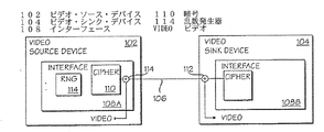
次に図1を参照すると、一実施形態により、本発明の概要を例示した構成図が示されている。図に示されたように、ビデオ・ソース・デバイス102とビデオ・シンク・デバイス104が、デジタル・ビデオ・リンク106によって互いに結合されている。ビデオ・ソース・デバイス102は、デジタル・ビデオ・リンク106を介して、ビデオ・シンク・デバイス104にビデオ・コンテンツを提供する。本発明によれば、ビデオ・ソース・デバイス102およびビデオ・シンク・デバイス104は、対称暗号化/解読プロセスを共同して実施できるようになっている。その結果、より堅固に暗号化されたデジタル形式のビデオ・コンテンツを、ビデオ・リンク106を介してビデオ・ソース・デバイス102からビデオ・シンク・デバイス104に提供することができ、伝送中にビデオ・コンテンツを盗用するのがより困難になる。
【0009】
以下でより詳細に説明するために本明細書に組み込まれた教示を除き、ビデオ・ソース・デバイス102およびビデオ・シンク・デバイス104は、どちらも当分野で知られた広範囲にわたるこうしたデバイスを表すように意図されている。ビデオ・ソース・デバイスには、すべてのサイズ(手のひらサイズのデバイスからデスクトップおよびそれ以上のデバイス)のコンピュータ、セットアップ・ボックス、またはDVDプレーヤが含まれるが、これらに限定されることはなく、ビデオ・シンク・デバイスには、CRTモニタ、フラット・パネル・ディスプレイ、またはテレビ受像機が含まれるが、これらに限定されることはない。デジタル・ビデオ・リンク106は、動作要件(すなわち、速度、ビット・レートなど)に合致しており、ビデオ・ソース・デバイス102とビデオ・シンク・デバイス104(以下、簡単にそれぞれソース・デバイスおよびシンク・デバイスと呼ぶ)との間で制御情報が交換できるようにメカニズムが(ハードウェア内にあるかまたはプロトコルを介して)提供される限り、いくつかの機械的および電気的形式のうちいずれか1つで実施することができる。
【0010】
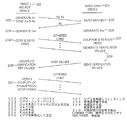
図2は、一実施形態により、ソース・デバイスからシンク・デバイスにビデオ・コンテンツを提供するための、対称暗号化/解読プロセス・ベースの方法を示す図である。この実施形態では、ソース・デバイス102およびシンク・デバイス104それぞれには、認証局によって秘密鍵のアレイと相補的な識別子が与えられていると仮定する。図に示されたように、電源を投入するかまたはリセットすると、ソース・デバイス102は、第1に、対称暗号化/解読プロセスの基本値をシンク・デバイス104に提供する(ブロック202)。例示した実施形態では、基本値は乱数(An)である。Anは、当分野で知られたいくつかの技法のうちのいずれか1つによって生成することができる。さらに、ソース・デバイス102は、シンク・デバイス104にそれ自体の識別子(Ak)も提供する(ブロック202)。これに応答して、シンク・デバイス104はそれ自体の識別子(Bk)とともに答える(ブロック203)。上記の情報を交換すると、ソース・デバイス102およびシンク・デバイス104は、AkおよびBkを使用して認証鍵(Km)のコピーをそれぞれ独自で生成する(ブロック204および205)。例示した実施形態では、ソース・デバイス102は、Bkで索引付けされた提供されたアレイの秘密鍵を合計することによってKmのコピーを生成し、シンク・デバイス104は、Akで索引付けされて提供されたアレイの秘密鍵を合計することによってKmのコピーを生成する。この時点で、ソース・デバイス102およびシンク・デバイス104がどちらも認可デバイスであれば、双方が共通の秘密認証鍵Kmを所有し、共用する。
【0011】
一実施形態では、ソース・デバイス102およびシンク・デバイス104には、認証局によってそれぞれ40の56ビット秘密鍵アレイが事前に提供されている。Anは64ビットの乱数であり、Kmは56ビット長である。前述の認証プロセスに関する詳細は、発明者ならびに譲受人が本出願と共通である、1999年3月24日付け出願の「Method and Apparatus for the Generation of Cryptographic Key」という名称の同時係属の米国特許出願第09/275722号を参照されたい。
【0012】
シンク・デバイス104が認証を受けていると、ソース・デバイス102は、シンク・デバイス104にビデオ・コンテンツを伝送する前に、ビデオ・コンテンツを暗号形式に暗号化する。ソース・デバイス102は、対称暗号化/解読プロセスを使用し、乱数(An)ならびに独自に生成された認証鍵(Km)を使用して、ビデオ・コンテンツを暗号化する(ブロック206)。暗号形式のビデオ・コンテンツを受け取ると、シンク・デバイス104は、同じ対称暗号化/解読プロセスを使用し、提供されたAnならびに独自に生成されたKmのコピーを使用して、暗号化されたビデオ・コンテンツを解読する(ブロック207)。
【0013】
本発明によれば、ビデオ・コンテンツの暗号化に不可欠な部分として、ソース・デバイス102は検証基準値のセットを所定の方法で導出する(ブロック208)。同様に、ビデオ・コンテンツの対称解読に不可欠な部分として、シンク・デバイス104も、検証値のセットを所定の方法で導出し、これらの導出された検証値をソース・デバイス102に伝送する(ブロック209)。これらそれぞれの検証値を受け取ると、ソース・デバイス102は、受け取った検証値を対応する検証基準値の1つと照らし合わせ、暗号化されたビデオ・コンテンツが本当にシンク・デバイス104によって正しく解読されているかどうかを判定および確認する(ブロック210)。
【0014】
例示した実施形態では、ソース・デバイス102およびシンク・デバイス104は、どちらも検証基準値および検証値を連続して生成するが、検証値は、シンク・デバイス104からソース・デバイス102に対して所定の間隔で定期的に提供されてもよい。
【0015】
一実施形態では、検証基準値および検証値はすべて64ビット長であり、シンク・デバイス104は、初期時およびその後64フレームごとに検証値をソース・デバイス102に提供する。
【0016】
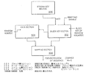
図3a〜3bは、一実施形態により、対称暗号化/解読プロセスを詳細に示す図である。この実施形態では、ビデオ・コンテンツはマルチフレーム・ビデオ・コンテンツであり、それぞれのフレームが複数ラインのビデオ・コンテンツを有するものと仮定する。フレームの2つのラインの間は、一般に水平帰線期間すなわち水平帰線消去期間(HBI)と呼ばれる、シンク・デバイスがそれ自体水平に「戻る」期間である。同様に、2つのフレームの間は、一般に垂直帰線期間または垂直帰線消去期間(VBI)と呼ばれる、シンク・デバイスがそれ自体を垂直に「戻る」期間である。
【0017】
ソース・デバイス102は、第1に、伝送セッション用のセッション鍵(Ks)を生成する(ブロック302)。例示した実施形態では、Ksは、認証鍵Kmをブロック暗号鍵として使用し、C1クロックを適用して、前述の乱数Anのブロック暗号化によって生成される。伝送セッションの持続時間は適用例によって異なる。これは典型的には、ビデオ・コンテンツの普通の境界設定に対応しており、たとえば、1本の映画の伝送を1伝送セッションで構成するか、または連続ホーム・コメディの1話の伝送を1伝送セッションで構成することができる。
【0018】
セッション鍵Ksを生成すると、ソース・デバイス102は第2の乱数の初期バージョン(M0)を生成する(ブロック304)。例示した実施形態では、ソース・デバイス102は第1に、前述の乱数Anおよびセッション鍵Ksによるストリーム暗号を(他の入力乱数として、およびストリーム暗号鍵としての2つの役割で)使用し、C2クロックを適用して、擬似ランダム・ビット・シーケンスを(クロックあたりpビットで)生成する。ソース・デバイス102は、ビット・シーケンスが生成されるときに、擬似ランダム・ビット・シーケンスからM0を導出する。
【0019】
次に、ソース・デバイス102は、次のフレーム用のフレーム鍵(Ki)を生成する(ブロック306)。例示した実施形態では、Kiは、セッション鍵Ksをブロック暗号鍵として使用し、C3クロックを適用して、第2の乱数の直前バージョンMi−1をブロック暗号化することで生成される。すなわち、第1のフレーム、フレーム1では、フレーム鍵K1は、Ksを使用し、C3クロックを適用して、前述の第2の乱数M0の初期バージョンをブロック暗号化することで生成される。さらに、このオペレーションは、その後も垂直帰線消去期間ごとに、次のフレーム、フレーム2、フレーム3と繰り返される。
【0020】
フレーム鍵Kiを生成すると、ソース・デバイス102は、第2の乱数の現在のバージョン(Mi)を生成する(ブロック302)。例示した実施形態では、ソース・デバイス102は第1に、第2の乱数の前のバージョンMi−1およびフレーム鍵Kiによるストリーム暗号を(他の入力乱数として、およびストリーム暗号鍵としての2つの役割で)使用し、C4クロックを適用して、擬似ランダム・ビット・シーケンスを(クロックあたりpビットで)生成する。ソース・デバイス102は、ビット・シーケンスが生成されるときに、擬似ランダム・ビット・シーケンスからMiを導出する。
【0021】
第2の乱数の現在のバージョンMiを生成すると、ソース・デバイス102はフレームを暗号化するために、擬似ランダム・ビット・シーケンスを(クロックあたりpビットで)再度生成する(ブロック308)。例示した実施形態では、ソース・デバイス102は、第2の乱数の直前バージョンMi−1およびフレーム鍵Kiによるストリーム暗号を(他の入力乱数として、およびストリーム暗号鍵としての2つの役割で)使用し、C5クロック・サイクルを適用して、擬似ランダム・ビット・シーケンスを生成する。ビデオ・コンテンツは、ビデオ・ストリームおよび擬似ランダム・ビット・シーケンスで排他的論理和(XOR)オペレーションを実行することによって暗号化される。擬似ランダム・ビット・シーケンスは、クロックあたりのRGB信号のピクセルを暗号化するのに十分なレートで生成されるのが好ましい。したがって、C5は、ピクセルあたりのビット数に、線あたりのピクセル数、ならびにフレームあたりの線数を掛けた数に等しい。
【0022】
例示した実施形態では、擬似ランダム・ビット・シーケンスを生成する間に、MiおよびKiを連続して変換するストリーム暗号が使用される。さらに、フレームの水平帰線消去期間でKiの現在の状態を連続的に修正することにより、擬似ランダム・ビット・シーケンスの不確定性を増加させることで、暗号化されたビデオ・コンテンツの堅固さがより強くなる(ブロック310)。
【0023】
シンク・デバイス104でも同じ方法で、伝送セッション用のセッション鍵(Ks)を第1に生成する(ブロック312)。セッション鍵Ksを生成すると、シンク・デバイス104は、第2の乱数の初期バージョン(M0)を生成する(ブロック314)。次にシンク・デバイス104は、次のフレーム用のフレーム鍵(Ki)および第2の乱数(Mi)を生成する(ブロック316)。このオペレーションは、その次のフレームでも、垂直帰線消去間隔ごとに引き続き同様に繰り返される。その間に、フレーム鍵KiおよびMiをそれぞれ生成した後、シンク・デバイス104は、フレームを解読するために対応する擬似ランダム・ビット・シーケンスを生成する(ブロック318)。暗号化されたビデオ・コンテンツは、ビデオ・ストリームおよび対応する擬似ランダム・ビット・シーケンスで、排他的論理和(XOR)オペレーションを実行することによって解読される。シンク・デバイス104は、擬似ランダム・ビット・シーケンスを生成する間に、連続的にMiおよびKiを変換するストリーム暗号も使用する。さらに、Kiはフレームの水平帰線消去期間で連続して修正される(ブロック320)。Ki、擬似ランダム・ビット・シーケンス、およびMiは、ソース・デバイス102について前述したように、対称的に生成される。
【0024】
一実施形態では、Ksおよび各Kiは、どちらも84ビット長である。C1およびC3はどちらも48クロック長である。各ピクセルは24ビットであり、擬似ランダム・ビット・シーケンスは、クロックあたり24ビットで生成される。各Miは64ビット長、C3およびC4は56クロック長である。64ビットの各Miは、最後の4クロックそれぞれから「低位の」16ビット・ストリーム暗号出力を連結することによって形成される。
【0025】
したがって、ビデオ・コンテンツは、著作権侵害の危険性が少ない状態でリンク106を介して堅固さが高められた暗号化形式でソース・デバイス102からシンク・デバイス104へ伝送できるので有利である。
【0026】
図4は、一実施形態により、図1のビデオ・ソース・デバイスおよびシンク・デバイスをより詳細に示す図である。図に示されるように、ビデオ・ソース・デバイス102およびシンク・デバイス104には、リンク106の両端に配置されたインターフェース108aおよび108bが含まれる。インターフェース108aおよび108bに、それぞれ、前述のように本発明のビデオ・コンテンツを保護する方法を実施するために、本発明の暗号110およびXOR112を設けるのが望ましい。さらに、説明しやすいように、インターフェース108aには別の乱数発生器114も備えられているように図示してある。前にも述べたように、ビデオ・ソース・デバイス102およびシンク・デバイス104は、インターフェース108aおよび108bを除き、その他の点では当分野で知られた広範なカテゴリを表すことが意図されている。
【0027】
乱数発生器114は、前述の乱数Anを生成する際に使用される。乱数発生器114は、ハードウェアまたはソフトウェアにおいて、当分野で知られたいくつかの技法のうちのいずれか1つで実施することができる。代替の実施形態では、当分野の技術者であれば、以下の説明から、Anを生成する際に別々の乱数発生器を使用せずに暗号110を使用することもできることが明らかであろう。
【0028】
暗号110は、ブロック・モード・オペレーションまたはストリーム・モード・オペレーションのいずれかで動作可能な、新規な組み合わされたブロック/ストリーム暗号である。本発明のビデオ・コンテンツ保護方法を実施する際に暗号110が使用されるが、前述のセッション鍵Ksおよびフレーム鍵Kiを生成する場合にはブロック・モードで使用され、様々なフレーム(およびそれらがそれぞれのビット・シーケンスから導出される場合は間接的にMi)用の擬似ランダム・ビット・シーケンスを生成する場合にはストリーム・モードで使用される。
【0029】
ソース・デバイス102では、ビデオ・コンテンツを暗号化し、これを、インターフェース108aの暗号110によって生成された擬似ランダム・ビット・シーケンスと組み合わせる際に、XOR 112が使用される。シンク・デバイス104では、暗号化されたビデオ・コンテンツを解読し、これを、インターフェース108bの暗号110によって生成された擬似ランダム・ビット・シーケンスと組み合わせる際に、XOR 112が使用される。
【0030】
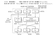
図5は、一実施形態により、図4の組み合わされたブロック/ストリーム暗号をより詳細に示す図である。図に示されるように、組み合わされたブロック/ストリーム暗号110には、ブロック鍵セクション502、データ・セクション504、ストリーム鍵セクション506、およびマッピング・セクション508が含まれ、互いに結合されている。ブロック鍵セクション502およびデータ・セクション504は、ブロック・モードならびにストリーム・モードの両方のオペレーションで使用されるが、ストリーム鍵セクション506およびマッピング・セクション508は、ストリーム・モード・オペレーションでのみ使用される。
【0031】
簡単に言えば、ブロック・モードでは、ブロック鍵セクション502には、前述の認証鍵Kmまたはセッション鍵Ksなどのブロック暗号鍵が提供されるが、データ・セクション504には、前述の乱数Anまたは導出された乱数Mi−1などの平文が提供される。「鍵再入力イネーブル」信号が「ディセーブル」に設定され、ブロック鍵セクション502がストリーム鍵セクション506から動作可能にデカップリングされる。各クロック・サイクル中に、ブロック暗号鍵ならびに平文が変換される。ブロック暗号鍵は独立して変換されるが、平文の変換はブロック暗号鍵で実行される変換に依存する。所望数のクロック・サイクル経過後、提供された平文は暗号化テキストに変換される。前述のビデオ・コンテンツ保護方法では、ブロック鍵セクション502にKmが提供され、データ・セクション504にAnが提供されると、暗号化されたAnが読み出されて、セッション鍵Ksとして使用される。ブロック鍵セクション502にKsが提供され、データ・セクション504にMi−1が提供されると、暗号化されたMi−1が読み出されて、フレーム鍵Kiとして使用される。
【0032】
暗号化された平文を解読するには、前述と同じ方法でブロック鍵セクション502とデータ・セクション504を使用して中間「鍵」が生成され、離れた場所(格納場所は図示せず)に格納される。格納された中間「鍵」は、その後、予約された順序で暗号化されたテキストに適用され、その結果、暗号化されたテキストが元の平文に解読される。暗号化されたテキストを解読する他の方法については、ブロック鍵セクション502およびデータ・セクション504について、それぞれ一実施形態により図6〜7を参照しながら詳細に述べた後に説明する。
【0033】
ストリーム・モードでは、ストリーム鍵セクション506に前述のセッション鍵Ksまたはフレーム鍵Kiなどのストリーム暗号鍵が提供される。ブロック鍵セクション502およびデータ・セクション504には、前述のセッション/フレーム鍵Ks/Kiおよび導出された乱数Mi−1などの乱数が提供される。「鍵再入力イネーブル」信号が「ディセーブル」に設定され、ブロック鍵セクション502がストリーム鍵セクション506に動作可能に結合される。ブロック鍵セクション502に格納された乱数の現在の状態を動的に修正するために、前述の水平帰線消去期間などの所定の期間で定期的にストリーム鍵セクション506を使用して、1つまたは複数のデータ・ビットを生成する。各クロック・サイクル中に、所定の期間の間、ブロック鍵セクション502に格納された乱数とデータ・セクション504の両方が変換される。ブロック鍵セクション502に提供された乱数は独立して変換されるが、データ・セクション504に提供された乱数の変換は、ブロック鍵セクション502で実行される変換に依存する。マッピング・ブロック506は、新しく変換された状態の2つの乱数からそれぞれサブセットを取り出し、これらを減らして1ビットの擬似ランダム・ビット・シーケンスを生成する。したがって、所望数のクロック・サイクルで、所望の長さの擬似ランダム・ビット・シーケンスが生成される。
【0034】
例示した実施形態では、「鍵再入力イネーブル」信号の使用により、「鍵再入力イネーブル」信号(「ディセーブル」状態に設定されている)によって出力が有効に廃棄されるため、ブロック・モードの間もストリーム鍵セクション506は動作状態のままとすることが可能である。
【0035】
図6は、一実施形態により、図5のブロック鍵セクションをより詳細に示す図である。図に示されるように、ブロック鍵セクション502にはレジスタ602a〜602c、置換ボックス604、および線形変換ユニット606が含まれる。ブロック・モードでは、レジスタ602a〜602cが集合的に、認証鍵Kmまたはセッション鍵Ksなどのブロック暗号鍵に初期設定される。ストリーム・モードでは、レジスタ602a〜602cが集合的に、セッション鍵Ksまたはフレーム鍵Kiなどの乱数に初期設定される。各ラウンドで、置換ボックス604および線形変換ユニット606がレジスタ602a〜602cのコンテンツを修正する。より具体的に言えば、置換ボックス604はレジスタ602aのコンテンツを受け取り、これを修正した後、置換されたコンテンツをレジスタ602cに格納する。同様に、線形変換ユニット606は、レジスタ602bおよび602cのコンテンツを受け取り、これらを線形変換した後、線形変換されたコンテンツをそれに対応してレジスタ602aおよび602bに格納する。
【0036】
置換ボックス604および線形変換ユニット606は、よく知られた暗号化原理に従って様々な方法で実施することができる。特有の一実施については、図7の説明の後でより詳細に説明する。
【0037】
図7は、一実施形態により、図5のブロック・データ・セクションをより詳細に示す図である。例示した実施形態では、線形変換ユニット706がレジスタ702b〜702cのコンテンツを変換する際にレジスタ602bのコンテンツも考慮に入れる点を除き、データ・セクション504がブロック鍵セクション502と同様に構築される。ブロック・モードでは、レジスタ702a〜702cが集合的に、前述の乱数Anまたは導出された乱数Mi−1などのターゲットの平文で初期設定される。ストリーム・モードでは、レジスタ702a〜702cが集合的に、乱数で初期設定される。各ラウンドで、置換ボックス704および線形変換ユニット706は、前述の相違点を除き、ブロック鍵セクション502で前述したようにレジスタ702a〜702cのコンテンツを修正する。
【0038】
さらにもう一度、置換ボックス604および線形変換ユニット606を、よく知られた暗号化原理に従って様々な方法で実施することができる。
【0039】
前述の実施形態の一実施では、レジスタ602a、602b、602c、702a、702b、702cは、それぞれ28ビット幅である。[レジスタ602a〜602cまたは702a〜702cが、84ビットより小さい鍵値または乱数で、集合的に初期設定される場合は必ず、84ビットより小さい数は低位のビット位置に初期設定され、高位のビット位置にはゼロが埋め込まれる。]さらに、置換ボックス604または704の各セットは、4入力×4出力の置換ボックス7つで構成される。線形変換ユニット606または706は、(それぞれが7つの出力を生成する)8つの拡散ネットワークからの出力を組み合わせることによって、それぞれ56の出力値を生成する。より具体的に言えば、置換ボックス604/704および線形変換ユニット606/706のオペレーションは、4つのテーブルに従って指定される。置換ボックス604/704の場合、ボックスJへのI番目の入力は、レジスタ602a/702aのビットI*7+Jであり、ボックスJの出力Iは、レジスタ602c/702cのビットI*7+Jへ進む。[ビット0は最下位ビットである。]各拡散ネットワーク(線形変換ユニット606ならびに706)では、入力は一般にI0〜I6と表示され、出力はO0〜O6と表示される。線形変換ユニット706の各拡散ネットワークに対する特別入力は、K0〜K6と表示される。
【表1】

図5を再度参照すると、中間「鍵」を生成し、それを後ろ向きに適用することによって、暗号化されたテキストを解読できることに留意されたい。あるいは、逆の置換ボックス604/704および線形変換ユニット606/706が含まれるか、またはこれらが逆の方法で動作するように動的に再構成できる実施形態では、暗号化されたテキストを以下のように解読することができる。第1に、平文を暗号化する際に使用する暗号鍵がブロック鍵セクション502にロードされ、ブロック鍵セクション502がR−1ラウンドだけ先に進められることになり、すなわち、平文の暗号化に適用されたラウンド数(R)よりも1ラウンド短くなる。初期のR−1ラウンド終了後、暗号化されたテキストがデータ・セクション504にロードされ、ブロック鍵セクション502およびデータ・セクション504の両セクションは「後ろ向き」に動作するものであって、すなわち、置換ボックス604/704および線形変換ユニット606/706がそれぞれ逆の置換および線形変換を適用する。
【0041】
図8a〜8cは、一実施形態により、図5のストリーム鍵セクションをより詳細に示す図である。図8aに示されるように、ストリーム鍵セクション506には、いくつかの線形フィードバック・シフト・レジスタ(LFSR)802および結合器関数804が含まれ、図のように互いに結合されている。LFSR 802は集合的に、たとえば前述のフレーム鍵Kiなどのストリーム暗号鍵で初期設定される。オペレーション中には、ストリーム暗号鍵がLFSR 802を通って連続的にシフトされる。選択出力がLFSR 802から取り出され、結合器関数804を使用してこの選択出力が結合される。ストリーム・モード(このモードの下では、鍵再入力が可能である)では、結合された結果を使用して、ブロック鍵セクション502内でのブロック暗号鍵のその後の現在の状態が動的に修正される。
【0042】
例示した実施形態では、長さの異なる4つのLFSRが使用される。3セットの出力が4つのLFSRから取り出される。LFSRによって表される多項式および3セットのLFSR出力のビット位置は、以下の表によって得られる。
【表5】
結合された結果は、LFSR出力の第1および第2のセットをそれぞれ結合器関数802へのデータ入力および制御入力として使用して、LFSR出力の第3のセットから生成される。LFSR出力の第3のセットは、単一ビットに結合される。ストリーム・モード(このモードの下では、鍵再入力が可能である)では、結合された単一ビットを使用して、ブロック鍵セクション502でのブロック暗号鍵のその後の現在の状態の所定ビットを動的に修正する。
【0044】
図8bは、一実施形態により、結合器関数804を詳細に示す図である。図に示されるように、結合器関数804にはシャッフル・ネットワーク806およびXOR 808a〜808bが含まれ、これら相互とLFSR 802は図のように直列に結合される。例示した実施形態では、シャッフル・ネットワーク806には、相互に直列に結合された4つのバイナリ・シャッフル・ユニット810a〜810dが含まれ、最初と最後のバイナリ・シャッフル・ユニット810aおよび810dは、それぞれXOR 808aおよび808bに結合される。XOR 808aは、LFSR出力の第1のグループを取り、これらをシャッフル・ネットワーク806への単一のビット入力として結合する。バイナリ・シャッフル・ユニット810a〜810dは直列に伝播し、XOR 808aの出力をシャッフルする。LFSR出力の第2のグループは、バイナリ・シャッフル・ユニット810a〜810dのうちの対応するところで、シャッフルを制御する際に使用される。XOR 808bは、LFSR出力の第3のセットと最後のバイナリ・シャッフル・ユニット810dの出力とを結合する。
【0045】
図8cは、一実施形態により、1つのバイナリ・シャッフル・ユニット810*(*はa〜dのうちの1つ)を詳細に示す図である。各バイナリ・シャッフル・ユニット810*には、2つのフリップフロップ812aおよび812b、ならびにいくつかのセレクタ814a〜814cが含まれ、図のように互いに連結されている。フリップフロップ812aおよび812bは、2つの状態値(A、B)を格納するのに使用される。各セレクタ814a、814b、または814cは、第2グループのLFSR出力のうち対応する1つを制御信号として受け取る。セレクタ814a〜814bは、それぞれ、XOR 808aの出力または直前のバイナリ・シャッフル・ユニット810*も入力として受け取る。セレクタ814a〜814bは、格納された2つの状態値のうちの1つを出力し、格納された値を選択信号の状態に従ってシャッフルならびに修正するために、フリップフロップ812a〜812bに結合される。より具体的に言えば、例示した実施形態では、格納された状態値が(A、B)であり、入力値および選択値が(D、S)である場合、バイナリ・シャッフル・ユニット810*はAを出力し、Sの値が「0」であれば(B、D)を格納する。バイナリ・シャッフル・ユニット810*は、Sの値が「1」であれば、Bを出力して(D、A)を格納する。
【0046】
再度図5に戻ると、図に示し前述したように、マッピング関数508は、ブロック鍵セクション502およびデータ・セクション504から選択されたレジスタのコンテンツに基づいて、擬似ランダム・ビット・シーケンスを生成する。ブロック鍵セクション502およびデータ・セクション504が図6〜7に示されるそれぞれの実施形態に従って実施される一実施形態では、マッピング関数508は、レジスタ(KyおよびKz)602b〜602cおよびレジスタ(ByおよびBz)702b〜702cのコンテンツに基づいて、クロックあたり24ビットで擬似ランダム・ビット・シーケンスを生成する。より具体的に言えば、以下の公式に従って、9つの項でXORオペレーションを実行することによって、24ビットそれぞれが生成される。
【数1】
上式で、「○のなかの+」は、論理XOR関数を表し、「・」は論理AND関数を表し、24出力ビットの入力値BおよびKは、以下のようになる。
【表6】
以上、ビデオ・コンテンツが伝送中に未許可でコピーされるのを防ぐために暗号化および解読するための新しい方法および装置について述べてきた。
【0049】
エピローグ
以上の内容から、当分野の技術者であれば、本発明の多くの他の変形形態が可能であることを理解されよう。具体的に言えば、本発明はインターフェース108aおよび108bで実施されるように説明してきたが、論理の中には、ビデオ・ソース・デバイスおよびビデオ・シンク・デバイス102および104の他の構成要素で分配できるものもある。さらに、非LFSRベースのストリーム鍵セクション、前述よりも多いか少ないブロック鍵レジスタ、前述よりも大きいか小さいブロック鍵レジスタ、代替の置換パターンを含む前述よりも多いか少ない置換ユニット、ならびに異なる線形変換ユニットも使用することができる。したがって、本発明は、記載された細部に限定されるものではなく、添付の特許請求の範囲の精神および範囲内であれば修正および変更を実施することができる。
【図面の簡単な説明】
【図1】 一実施形態により、本発明の概要を示す図である。
【図2】 一実施形態により、ソース・デバイスからシンク・デバイスにビデオ・コンテンツを提供するための、対称暗号化/解読プロセス・ベースの方法を示す図である。
【図3】 一実施形態により、図2の対称暗号化/解読プロセスを示す図である。
【図4】 一実施形態により、図1のビデオ・ソース・デバイスおよびシンク・デバイスをより詳細に示す図である。
【図5】 一実施形態により、図4の組み合わされたブロック/ストリーム暗号をより詳細に示す図である。
【図6】 一実施形態により、図5のブロック鍵セクションをより詳細に示す図である。
【図7】 一実施形態により、図5のブロック・データ・セクションをより詳細に示す図である。
【図8】 一実施形態により、図5のストリーム鍵セクションをより詳細に示す図である。[0001]
(Background of the Invention)
(1. Field of the Invention)
The present invention relates to the field of content protection. More particularly, the present invention is directed to providing protection of digital video content to facilitate reliable transmission from a video source device to a video sink device.
[0002]
(2. Background information)
In general, packaging entertainment, education, art, etc. (hereinafter collectively referred to as “content”) in digital form provides higher audio and video quality than that in analog form. However, content producers, especially in the entertainment industry, are still reluctant to fully adopt digital formats. The primary reason is that digitized content is particularly prone to piracy. In general, unlike analog formats, where a certain amount of quality degradation occurs with each repeated copy, a copy of stolen digital content is virtually the same quality as the “Gold Master”. As a result, the industry has invested a great deal in developing and adopting techniques to protect the distribution and rendering of digital content.
[0003]
Historically, the communication interface between a video source device (such as a personal computer) and a video sink device (such as a monitor) is an analog interface. Thus, little focus has been placed on protecting transmissions between source and sink devices. With advances in integrated circuits and other related technologies, new types of digital interfaces have emerged between video source devices and sink devices. A new digital interface of this kind has become available, creating a new challenge of protecting digital video content. In general, many cryptographic techniques are known, but the amount of data, its streaming characteristics, operating characteristics such as bit rate, and the location of intelligence typically in the source device rather than the sink device are new. It presents a set of unique challenges that require innovative measures.
[0004]
(Summary of Invention)
For each transmission session in which multi-frame video content is transmitted to a video sink device, a session key is generated by the video source device. The video source device then uses at least this session key to facilitate the encryption of the corresponding frame of the multi-frame video content for transmission to the video sink device. Generate a frame key to be used.
[0005]
The present invention will now be described by way of example and not limitation, shown in the accompanying drawings, in which like reference numerals represent like elements.
[0006]
(Detailed description of the invention)
In the following description, various aspects of the present invention are described, and various details are set forth in order to provide a thorough understanding of the present invention. However, it will be apparent to those skilled in the art that the present invention may be practiced using only some or all of the present invention and that the present invention may be practiced without the specific details. In other instances, well-known features are omitted or simplified in order not to obscure the present invention.
[0007]
The various operations are described as a number of individual steps performed in sequence in a manner that is most useful in understanding the present invention. However, the order of description should not be construed to mean that these operations need to be performed in the order presented, i.e., are dependent on the order. Finally, the phrase “in one embodiment” used repeatedly may refer to the same embodiment, but need not be the same.
[0008]
Referring now to FIG. 1, a block diagram illustrating an overview of the present invention is shown, according to one embodiment. As shown in the figure,
[0009]
Except for the teachings incorporated herein to describe in more detail below,
[0010]
FIG. 2 is a diagram illustrating a symmetric encryption / decryption process based method for providing video content from a source device to a sink device according to one embodiment. In this embodiment, it is assumed that
[0011]
In one embodiment,
[0012]
If the
[0013]
In accordance with the present invention, as an integral part of video content encryption, the
[0014]
In the illustrated embodiment, both the
[0015]
In one embodiment, the verification reference value and the verification value are all 64 bits long, and the
[0016]
3a-3b illustrate in detail the symmetric encryption / decryption process according to one embodiment. In this embodiment, it is assumed that the video content is multi-frame video content and each frame has multiple lines of video content. Between the two lines of the frame is a period during which the sink device itself “returns” horizontally, commonly referred to as a horizontal blanking period or horizontal blanking period (HBI). Similarly, between two frames is a period during which the sink device “returns” itself vertically, commonly referred to as a vertical blanking interval or vertical blanking interval (VBI).
[0017]
The
[0018]
Having generated the session key Ks, the
[0019]
Next, the
[0020]
Having generated the frame key Ki, the
[0021]
Having generated the current version Mi of the second random number, the
[0022]
In the illustrated embodiment, a stream cipher that converts Mi and Ki sequentially while generating a pseudo-random bit sequence is used. In addition, the robustness of the encrypted video content is increased by increasing the uncertainty of the pseudo-random bit sequence by continuously modifying the current state of Ki during the horizontal blanking period of the frame. Becomes stronger (block 310).
[0023]
In the same manner, the
[0024]
In one embodiment, Ks and each Ki are both 84 bits long. Both C1 and C3 are 48 clocks long. Each pixel is 24 bits and a pseudo-random bit sequence is generated at 24 bits per clock. Each Mi is 64 bits long and C3 and C4 are 56 clocks long. Each 64-bit Mi is formed by concatenating the “low” 16-bit stream cipher output from each of the last 4 clocks.
[0025]
Thus, video content can be advantageously transmitted from the
[0026]
FIG. 4 is a diagram illustrating the video source device and sink device of FIG. 1 in more detail, according to one embodiment. As shown,
[0027]
The
[0028]
The
[0029]
At
[0030]
FIG. 5 is a diagram illustrating in more detail the combined block / stream cipher of FIG. 4 according to one embodiment. As shown, the combined block /
[0031]
Briefly, in block mode, the block
[0032]
To decrypt the encrypted plaintext, an intermediate “key” is generated using the block
[0033]
In the stream mode, the stream
[0034]
In the illustrated embodiment, the use of the “rekey re-enable” signal effectively discards the output due to the “re-key re-enable” signal (set to the “disabled” state), so that the block mode In the meantime, the stream
[0035]
FIG. 6 is a diagram illustrating the block key section of FIG. 5 in more detail, according to one embodiment. As shown, the block
[0036]
The
[0037]
FIG. 7 is a diagram illustrating the block data section of FIG. 5 in more detail, according to one embodiment. In the illustrated embodiment, the
[0038]
Again, the
[0039]
In one implementation of the foregoing embodiment, registers 602a, 602b, 602c, 702a, 702b, and 702c are each 28 bits wide. [When
[Table 1]
Referring back to FIG. 5, it should be noted that the encrypted text can be decrypted by generating an intermediate “key” and applying it backwards. Alternatively, in an embodiment that includes an
[0041]
8a-8c are diagrams illustrating in more detail the stream key section of FIG. 5 according to one embodiment. As shown in FIG. 8a, the stream
[0042]
In the illustrated embodiment, four LFSRs with different lengths are used. Three sets of outputs are taken from the four LFSRs. The polynomials represented by the LFSR and the bit positions of the three sets of LFSR outputs are obtained by the following table.
[Table 5]
The combined result is generated from the third set of LFSR outputs using the first and second sets of LFSR outputs as data and control inputs to
[0044]
FIG. 8b illustrates in detail the
[0045]
FIG. 8c illustrates in detail one
[0046]
Returning again to FIG. 5, as shown and described above, the
[Expression 1]
In the above equation, “+ in ○” represents a logical XOR function, “·” represents a logical AND function, and input values B and K of 24 output bits are as follows.
[Table 6]
Thus, a new method and apparatus has been described for encrypting and decrypting video content to prevent unauthorized copying during transmission.
[0049]
From the epilogue and beyond, those skilled in the art will appreciate that many other variations of the present invention are possible. Specifically, although the present invention has been described as being implemented at interfaces 108a and 108b, the logic may include other components of the video source device and
[Brief description of the drawings]
FIG. 1 illustrates an overview of the present invention, according to one embodiment.
FIG. 2 illustrates a symmetric encryption / decryption process based method for providing video content from a source device to a sink device according to one embodiment.
FIG. 3 illustrates the symmetric encryption / decryption process of FIG. 2 according to one embodiment.
4 illustrates the video source device and sink device of FIG. 1 in more detail, according to one embodiment.
FIG. 5 shows the combined block / stream cipher of FIG. 4 in more detail, according to one embodiment.
6 illustrates the block key section of FIG. 5 in more detail, according to one embodiment.
FIG. 7 illustrates the block data section of FIG. 5 in more detail, according to one embodiment.
FIG. 8 shows the stream key section of FIG. 5 in more detail, according to one embodiment.
Claims (6)
前記ビデオシンク機器にマルチフレーム・ビデオコンテンツを送信する伝送セッション毎にセッションキーを生成するステップと、
該セッションキーと乱数とを用いて、前記マルチフレーム・ビデオコンテンツのビデオ・フレームに関するフレームキーを生成するステップと、
該ビデオ・フレームを該生成したフレームキーを用いて暗号化するステップと、
を含んでおり、
前記フレームキーは、前記マルチフレーム・ビデオコンテンツの水平帰線消去期間において前記乱数を変更することによって該水平帰線消去期間に修正される
ことを特徴とする方法。In a method performed by a video source device to transmit multi-frame video content from a video source device to a video sink device,
Generating a session key for each transmission session for transmitting multi-frame video content to the video sink device;
Generating a frame key for a video frame of the multi-frame video content using the session key and a random number;
Encrypting the video frame with the generated frame key;
Contains
The frame key, method characterized in that it is fixed in the HBI by modifying the random number in the horizontal blanking interval of said multi-frame video content.
マルチフレーム・ビデオコンテンツの伝送セッション毎に生成されたセッションキーと乱数とを用いて、マルチフレーム・ビデオコンテンツの各ビデオ・フレームに関するフレームキーを生成するステップと、
前記ビデオ・フレームのビデオコンテンツを暗号化するために使用する疑似ランダムビット列を、前記フレームキーを用いて生成するステップと、
を含んでおり、
前記フレームキーは、前記マルチフレーム・ビデオコンテンツの水平帰線消去期間において前記乱数を変更することによって該水平帰線消去期間に修正される
ことを特徴とする方法。In a method performed by a video source device to transmit multi-frame video content from a video source device to a video sink device,
Generating a frame key for each video frame of the multi-frame video content using a session key and a random number generated for each transmission session of the multi-frame video content;
Generating a pseudo-random bit string to be used for encrypting video content of the video frame using the frame key;
Contains
The frame key, method characterized in that it is fixed in the HBI by modifying the random number in the horizontal blanking interval of said multi-frame video content.
該ブロック暗号器に接続されていて、該マルチフレーム・ビデオコンテンツのビデオ・フレームを送信のために暗号化するための疑似ランダムビット列を、前記ビデオ・フレームに関するフレームキーを用いて生成するストリーム暗号器とを備え、
前記フレームキーは、前記マルチフレーム・ビデオコンテンツの水平帰線消去期間において前記乱数を変更することによって該水平帰線消去期間に修正される
ことを特徴とするビデオソース機器。A block for generating a session key for each transmission session for transmitting multi-frame video content to a video sink device, and generating a frame key for a video frame of the multi-frame video content using the session key and a random number An encryption device,
A stream cipher that is connected to the block cipher and generates a pseudo-random bit sequence for encrypting a video frame of the multi-frame video content for transmission using a frame key for the video frame And
The frame keys, video source device characterized in that it is fixed in the HBI by modifying the random number in the horizontal blanking interval of said multi-frame video content.
受信セッション毎に該受信セッションの間のみ有効なセッションキーを生成するステップと、
前記セッションキーと乱数とを用いて、前記マルチフレーム・ビデオコンテンツのビデオ・フレームに関するフレームキーを生成するステップと、
前記ビデオ・フレームを、前記フレームキーを解読キーとして用いて解読することにより該マルチフレーム・ビデオコンテンツを再生するステップと、
を含んでおり、
前記フレームキーは、前記マルチフレーム・ビデオコンテンツの水平帰線消去期間において前記乱数を変更することによって該水平帰線消去期間に修正される
ことを特徴とする方法。In a method performed by a video sink device that receives multi-frame video content from a video source device,
Generating a session key valid only during the receiving session for each receiving session;
Generating a frame key for a video frame of the multi-frame video content using the session key and a random number;
Playing the multi-frame video content by decrypting the video frame using the frame key as a decryption key;
Contains
The frame key, method characterized in that it is fixed in the HBI by modifying the random number in the horizontal blanking interval of said multi-frame video content.
前記ビデオソース機器からのマルチフレーム・ビデオコンテンツの伝送セッション毎に生成されたセッションキーと乱数とに基づいて、該マルチフレーム・ビデオコンテンツのビデオ・フレームに関するフレームキーを生成するステップと、
前記ビデオ・フレームのビデオコンテンツを解読するために使用する疑似ランダムビット列を、前記ビデオ・フレームに対応するフレームキーを用いて生成するステップと、
を含んでおり、
前記フレームキーは、前記マルチフレーム・ビデオコンテンツの水平帰線消去期間において前記乱数を変更することによって該水平帰線消去期間に修正される
ことを特徴とする方法。In a method performed by a video sink device that receives multi-frame video content from a video source device,
Generating a frame key relating to a video frame of the multi-frame video content based on a session key and a random number generated for each multi-frame video content transmission session from the video source device;
Generating a pseudo-random bit sequence used to decrypt the video content of the video frame with a frame key corresponding to the video frame;
Contains
The frame key, method characterized in that it is fixed in the HBI by modifying the random number in the horizontal blanking interval of said multi-frame video content.
該ブロック解読器に接続されていて、該マルチフレーム・ビデオコンテンツのビデオ・フレームを解読するための疑似ランダムビット列を、前記ビデオ・フレームに関するフレームキーを用いて生成するストリーム解読器とを備え、
前記フレームキーは、前記マルチフレーム・ビデオコンテンツの水平帰線消去期間において前記乱数を変更することによって該水平帰線消去期間に修正される
ことを特徴とするビデオシンク機器。A block for generating a session key for each reception session for receiving multi-frame video content from a video source device, and generating a frame key for a video frame of the multi-frame video content using the session key and a random number A decryptor,
A stream decoder connected to the block decoder and generating a pseudo-random bit sequence for decoding a video frame of the multi-frame video content using a frame key for the video frame;
The frame keys, video sink device, characterized in that it is fixed in the HBI by modifying the random number in the horizontal blanking interval of said multi-frame video content.
Applications Claiming Priority (3)
| Application Number | Priority Date | Filing Date | Title |
|---|---|---|---|
| US09/385,592 US6731758B1 (en) | 1999-08-29 | 1999-08-29 | Digital video content transmission ciphering and deciphering method and apparatus |
| US09/385,592 | 1999-08-29 | ||
| PCT/US2000/022785 WO2001017251A1 (en) | 1999-08-29 | 2000-08-17 | Digital video content transmission ciphering and deciphering met hod and apparatus |
Publications (3)
| Publication Number | Publication Date |
|---|---|
| JP2003508975A JP2003508975A (en) | 2003-03-04 |
| JP2003508975A5 JP2003508975A5 (en) | 2007-03-29 |
| JP4170620B2 true JP4170620B2 (en) | 2008-10-22 |
Family
ID=23522062
Family Applications (1)
| Application Number | Title | Priority Date | Filing Date |
|---|---|---|---|
| JP2001521065A Expired - Fee Related JP4170620B2 (en) | 1999-08-29 | 2000-08-17 | Method and apparatus for encryption and decryption of digital video content transmission |
Country Status (10)
| Country | Link |
|---|---|
| US (2) | US6731758B1 (en) |
| EP (1) | EP1212893B1 (en) |
| JP (1) | JP4170620B2 (en) |
| KR (1) | KR100478507B1 (en) |
| CN (1) | CN1235405C (en) |
| AU (1) | AU6918400A (en) |
| DE (1) | DE60017155T2 (en) |
| HK (1) | HK1043683A1 (en) |
| TW (1) | TW501370B (en) |
| WO (1) | WO2001017251A1 (en) |
Families Citing this family (50)
| Publication number | Priority date | Publication date | Assignee | Title |
|---|---|---|---|---|
| JPH10301492A (en) * | 1997-04-23 | 1998-11-13 | Sony Corp | Enciphering device and method therefor, decoding device and method therefor, and information processing device and method therefor |
| US8055588B2 (en) * | 1999-05-19 | 2011-11-08 | Digimarc Corporation | Digital media methods |
| US7068786B1 (en) | 1999-08-29 | 2006-06-27 | Intel Corporation | Dual use block/stream cipher |
| US6477252B1 (en) | 1999-08-29 | 2002-11-05 | Intel Corporation | Digital video content transmission ciphering and deciphering method and apparatus |
| US6920221B1 (en) | 1999-08-29 | 2005-07-19 | Intel Corporation | Method and apparatus for protected exchange of status and secret values between a video source application and a video hardware interface |
| US6731758B1 (en) * | 1999-08-29 | 2004-05-04 | Intel Corporation | Digital video content transmission ciphering and deciphering method and apparatus |
| US6947558B1 (en) | 1999-08-29 | 2005-09-20 | Intel Corporation | Stream cipher having a shuffle network combiner function |
| US7356848B1 (en) * | 1999-10-19 | 2008-04-08 | Thomson Licensing | System and method of verifying authorization for communicating protected content |
| US7003107B2 (en) | 2000-05-23 | 2006-02-21 | Mainstream Encryption | Hybrid stream cipher |
| US7277543B1 (en) * | 2000-11-14 | 2007-10-02 | Honeywell International Inc. | Cryptographic combiner using two sequential non-associative operations |
| US6909786B2 (en) * | 2001-01-09 | 2005-06-21 | D'crypt Private Limited | Cryptographic trap door with timed lock and controlled escrow |
| FI115356B (en) * | 2001-06-29 | 2005-04-15 | Nokia Corp | A method for processing audio-visual information in an electronic device, a system and an electronic device |
| KR100995439B1 (en) * | 2002-09-28 | 2010-11-18 | 주식회사 케이티 | Streaming security system using the Streaming data security apparatus and method |
| JP4214454B2 (en) * | 2002-12-13 | 2009-01-28 | ソニー株式会社 | Video signal processing system, video signal processing apparatus and method, recording medium, and program |
| CN1759562A (en) * | 2003-03-25 | 2006-04-12 | 独立行政法人情报通信研究机构 | Device, method, and program for encryption and decryption and recording medium |
| JP4710607B2 (en) * | 2003-07-14 | 2011-06-29 | ソニー株式会社 | Encryption device, encryption method and encryption program, decryption device, decryption method and decryption program, and recording medium |
| US7519274B2 (en) | 2003-12-08 | 2009-04-14 | Divx, Inc. | File format for multiple track digital data |
| US8472792B2 (en) | 2003-12-08 | 2013-06-25 | Divx, Llc | Multimedia distribution system |
| US20050213751A1 (en) * | 2004-03-26 | 2005-09-29 | Apostolopoulos John J | Methods and systems for generating transcodable encrypted content |
| WO2005124681A1 (en) * | 2004-06-14 | 2005-12-29 | The University Of North Carolina At Greensboro | Systems and methods for digital content security |
| WO2006050009A1 (en) * | 2004-10-28 | 2006-05-11 | Macrovision Corporation | Content management for high definition television |
| KR100660850B1 (en) * | 2005-01-11 | 2006-12-26 | 삼성전자주식회사 | A Video On Demand system and a method for reconstructing a Video On Demand system |
| WO2006085283A1 (en) * | 2005-02-09 | 2006-08-17 | Koninklijke Philips Electronics N.V. | High speed encryption and decryption |
| EP1867190B1 (en) * | 2005-04-07 | 2009-08-19 | France Telecom | Managing access to multimedia contents |
| US7792293B2 (en) * | 2005-05-06 | 2010-09-07 | Rovi Solutions Corporation | Method and apparatus for modifying a subsequently generated control command in a content control system |
| WO2007043014A1 (en) * | 2005-10-13 | 2007-04-19 | Koninklijke Philips Electronics N.V. | Method of encrypted communication using a keystream |
| JP5200204B2 (en) | 2006-03-14 | 2013-06-05 | ディブエックス リミテッド ライアビリティー カンパニー | A federated digital rights management mechanism including a trusted system |
| CN100426859C (en) * | 2006-05-11 | 2008-10-15 | 蓝汛网络科技(北京)有限公司 | Selective encryption algorithm aiming at network video |
| JP4912797B2 (en) * | 2006-08-30 | 2012-04-11 | 三菱電機株式会社 | ENCRYPTION DEVICE, DECRYPTION DEVICE, ENCRYPTION METHOD, DECRYPTION METHOD, AND PROGRAM |
| KR100826522B1 (en) * | 2006-11-15 | 2008-04-30 | 삼성전자주식회사 | Apparatus and method for dynamic ciphering in mobile communication system |
| US20080159532A1 (en) * | 2006-12-29 | 2008-07-03 | Verma Rohit R | Architecture for supporting high definition content protection decryption over high definition multimedia interface links |
| EP4184341A1 (en) | 2007-01-05 | 2023-05-24 | DivX, LLC | Video distribution system including progressive playback |
| CN101669322B (en) * | 2007-05-08 | 2013-07-03 | 汤姆森特许公司 | Method and apparatus for adjusting decryption keys |
| US20080304664A1 (en) * | 2007-06-07 | 2008-12-11 | Shanmugathasan Suthaharan | System and a method for securing information |
| US20080309816A1 (en) * | 2007-06-15 | 2008-12-18 | Macrovision Corporation | Television content control system and method with cross-platform capability |
| JP5273963B2 (en) | 2007-07-23 | 2013-08-28 | 修 亀田 | Pseudorandom number generation method and apparatus, and encryption method and apparatus using pseudorandom number |
| WO2009065137A1 (en) | 2007-11-16 | 2009-05-22 | Divx, Inc. | Hierarchical and reduced index structures for multimedia files |
| US8259949B2 (en) | 2008-05-27 | 2012-09-04 | Intel Corporation | Methods and apparatus for protecting digital content |
| WO2010018611A1 (en) * | 2008-08-13 | 2010-02-18 | Thomson Licensing | Apparatus and method for encrypting image data, and decrypting the encrypted image data, and image data distribution system |
| KR101012334B1 (en) * | 2009-02-17 | 2011-02-09 | (주)티엔씨애드컴 | Apparatus for enabling advertisement on buoy and method thereof |
| EP2507995A4 (en) | 2009-12-04 | 2014-07-09 | Sonic Ip Inc | Elementary bitstream cryptographic material transport systems and methods |
| US9043827B1 (en) | 2009-12-16 | 2015-05-26 | Prime Research Alliance E, Inc. | Method and system for providing conditional access to encrypted content |
| US9247312B2 (en) | 2011-01-05 | 2016-01-26 | Sonic Ip, Inc. | Systems and methods for encoding source media in matroska container files for adaptive bitrate streaming using hypertext transfer protocol |
| US9467708B2 (en) | 2011-08-30 | 2016-10-11 | Sonic Ip, Inc. | Selection of resolutions for seamless resolution switching of multimedia content |
| US8806188B2 (en) | 2011-08-31 | 2014-08-12 | Sonic Ip, Inc. | Systems and methods for performing adaptive bitrate streaming using automatically generated top level index files |
| US8909922B2 (en) | 2011-09-01 | 2014-12-09 | Sonic Ip, Inc. | Systems and methods for playing back alternative streams of protected content protected using common cryptographic information |
| US9191457B2 (en) | 2012-12-31 | 2015-11-17 | Sonic Ip, Inc. | Systems, methods, and media for controlling delivery of content |
| CN113259731B (en) | 2015-01-06 | 2023-07-04 | 帝威视有限公司 | System and method for encoding content and sharing content between devices |
| CN110909375B (en) * | 2019-10-12 | 2022-04-08 | 浙江工业大学 | Address desensitization method for reserving distribution characteristics |
| CN114666624A (en) * | 2022-04-07 | 2022-06-24 | 乾三(北京)科技有限公司 | Video file encryption and decryption method |
Family Cites Families (37)
| Publication number | Priority date | Publication date | Assignee | Title |
|---|---|---|---|---|
| US3798360A (en) | 1971-06-30 | 1974-03-19 | Ibm | Step code ciphering system |
| US4004089A (en) | 1975-02-28 | 1977-01-18 | Ncr Corporation | Programmable cryptic device for enciphering and deciphering data |
| US4316055A (en) | 1976-12-30 | 1982-02-16 | International Business Machines Corporation | Stream/block cipher crytographic system |
| NL8301458A (en) | 1983-04-26 | 1984-11-16 | Philips Nv | METHOD FOR DISTRIBUTING AND USING ENCRYPTION KEYS. |
| US4613901A (en) | 1983-05-27 | 1986-09-23 | M/A-Com Linkabit, Inc. | Signal encryption and distribution system for controlling scrambling and selective remote descrambling of television signals |
| US4605820A (en) | 1983-11-10 | 1986-08-12 | Visa U.S.A. Inc. | Key management system for on-line communication |
| US4641102A (en) | 1984-08-17 | 1987-02-03 | At&T Bell Laboratories | Random number generator |
| DE59007408D1 (en) | 1989-02-08 | 1994-11-17 | Gretag Data Systems Ag | Method for cryptographic handling of data and cryptographic system. |
| JP2810103B2 (en) | 1989-04-28 | 1998-10-15 | パイオニア株式会社 | How to scramble television signals |
| US4991208A (en) * | 1990-03-29 | 1991-02-05 | Gte Laboratories Incorporated | Video control system having session encryption key |
| US5195136A (en) | 1991-09-30 | 1993-03-16 | Motorola, Inc. | Method and apparatus for data encryption or decryption |
| FR2698510B1 (en) | 1992-11-26 | 1994-12-23 | Schlumberger Ind Sa | Communication network. |
| US5341425A (en) | 1992-12-02 | 1994-08-23 | Scientific Atlanta, Inc. | Methods and apparatus for uniquely encrypting data at a plurality of data transmission sites for transmission to a reception site |
| US5341426A (en) | 1992-12-15 | 1994-08-23 | Motorola, Inc. | Cryptographic key management apparatus and method |
| JPH06350937A (en) | 1993-06-14 | 1994-12-22 | Pioneer Electron Corp | Picture synthesis reproduction device |
| KR950013093A (en) | 1993-10-19 | 1995-05-17 | 모리시타 요이찌 | Scramble Transfer Device and Random Number Generator |
| US5680131A (en) | 1993-10-29 | 1997-10-21 | National Semiconductor Corporation | Security system having randomized synchronization code after power up |
| US5533127A (en) | 1994-03-18 | 1996-07-02 | Canon Information Systems, Inc. | Encryption system |
| US5590194A (en) | 1994-08-09 | 1996-12-31 | Macrovision Corporation | Method of and apparatus for scrambling a video signal with full network transmission and recording capability |
| MY125706A (en) | 1994-08-19 | 2006-08-30 | Thomson Consumer Electronics | High speed signal processing smart card |
| US5673319A (en) | 1995-02-06 | 1997-09-30 | International Business Machines Corporation | Block cipher mode of operation for secure, length-preserving encryption |
| DE69634219D1 (en) | 1995-03-21 | 2005-03-03 | Sun Microsystems Inc | Video frame identifier detection |
| US5703950A (en) | 1995-06-30 | 1997-12-30 | Intermec Corporation | Method and apparatus for controlling country specific frequency allocation |
| US5852472A (en) | 1995-09-28 | 1998-12-22 | Intel Corporation | Method and apparatus for connecting video sources and video sinks |
| US5825879A (en) | 1996-09-30 | 1998-10-20 | Intel Corporation | System and method for copy-protecting distributed video content |
| US6167136A (en) | 1997-05-16 | 2000-12-26 | Software Security, Inc. | Method for preventing copying of digital video disks |
| US6005940A (en) | 1997-05-16 | 1999-12-21 | Software Security, Inc. | System for securely storing and reading encrypted data on a data medium using a transponder |
| JP3088337B2 (en) | 1997-05-30 | 2000-09-18 | 三菱電機株式会社 | Cryptographic processing device, IC card and cryptographic processing method |
| ES2236937T3 (en) | 1997-10-02 | 2005-07-16 | Canal+ Technologies | METHOD AND APPLIANCE FOR ENCRYPTED OR ENCRYPTED TRANSMISSION. |
| US6061449A (en) | 1997-10-10 | 2000-05-09 | General Instrument Corporation | Secure processor with external memory using block chaining and block re-ordering |
| WO1999019822A2 (en) | 1997-10-14 | 1999-04-22 | Microsoft Corporation | System and method for discovering compromised security devices |
| JPH11176091A (en) | 1997-12-15 | 1999-07-02 | Hitachi Ltd | Digital information input output device, receiving device, recording device, and reproducing device |
| US6118873A (en) | 1998-04-24 | 2000-09-12 | International Business Machines Corporation | System for encrypting broadcast programs in the presence of compromised receiver devices |
| US6345101B1 (en) | 1998-10-07 | 2002-02-05 | Jayant Shukla | Cryptographic method and apparatus for data communication and storage |
| US6452959B1 (en) | 1999-05-28 | 2002-09-17 | Dot Wireless, Inc. | Method of and apparatus for generating data sequences for use in communications |
| US6477252B1 (en) | 1999-08-29 | 2002-11-05 | Intel Corporation | Digital video content transmission ciphering and deciphering method and apparatus |
| US6731758B1 (en) * | 1999-08-29 | 2004-05-04 | Intel Corporation | Digital video content transmission ciphering and deciphering method and apparatus |
-
1999
- 1999-08-29 US US09/385,592 patent/US6731758B1/en not_active Expired - Lifetime
-
2000
- 2000-08-17 DE DE60017155T patent/DE60017155T2/en not_active Expired - Lifetime
- 2000-08-17 AU AU69184/00A patent/AU6918400A/en not_active Abandoned
- 2000-08-17 JP JP2001521065A patent/JP4170620B2/en not_active Expired - Fee Related
- 2000-08-17 WO PCT/US2000/022785 patent/WO2001017251A1/en active IP Right Grant
- 2000-08-17 KR KR10-2002-7002727A patent/KR100478507B1/en not_active IP Right Cessation
- 2000-08-17 EP EP00957587A patent/EP1212893B1/en not_active Expired - Lifetime
- 2000-08-17 CN CNB008150648A patent/CN1235405C/en not_active Expired - Fee Related
- 2000-08-29 TW TW089117509A patent/TW501370B/en not_active IP Right Cessation
-
2002
- 2002-07-22 HK HK02105398A patent/HK1043683A1/en not_active IP Right Cessation
-
2004
- 2004-04-14 US US10/825,009 patent/US7043021B2/en not_active Expired - Lifetime
Also Published As
| Publication number | Publication date |
|---|---|
| DE60017155T2 (en) | 2006-03-02 |
| EP1212893B1 (en) | 2004-12-29 |
| EP1212893A1 (en) | 2002-06-12 |
| DE60017155D1 (en) | 2005-02-03 |
| CN1235405C (en) | 2006-01-04 |
| JP2003508975A (en) | 2003-03-04 |
| TW501370B (en) | 2002-09-01 |
| US6731758B1 (en) | 2004-05-04 |
| US20040202321A1 (en) | 2004-10-14 |
| KR20020053808A (en) | 2002-07-05 |
| US7043021B2 (en) | 2006-05-09 |
| HK1043683A1 (en) | 2002-09-20 |
| AU6918400A (en) | 2001-03-26 |
| KR100478507B1 (en) | 2005-03-28 |
| CN1385032A (en) | 2002-12-11 |
| WO2001017251A1 (en) | 2001-03-08 |
Similar Documents
| Publication | Publication Date | Title |
|---|---|---|
| JP4170620B2 (en) | Method and apparatus for encryption and decryption of digital video content transmission | |
| JP4071496B2 (en) | Method and apparatus for encryption and decryption of digital video content transmission | |
| JP3789469B2 (en) | Method and apparatus for uniquely encrypting terminal data | |
| JP3655921B2 (en) | Method and apparatus for uniquely encrypting multiple services at a transmission point | |
| JP3901909B2 (en) | ENCRYPTION DEVICE AND RECORDING MEDIUM CONTAINING PROGRAM | |
| US7184550B2 (en) | Method and apparatus for simultaneous decryption and re-encryption of publicly distributed content via stream ciphers | |
| US6947561B1 (en) | Method and apparatus for protecting copy control information provided to a video recording device | |
| JP2007133400A (en) | Methods of scrambling and descrambling unit of data | |
| JP2007174491A (en) | Video image information encryption device, decryption key information preparation device, video image information decryption device, video reproducing device, and network system | |
| JP3526523B2 (en) | Secret key transmission method | |
| JPH09307546A (en) | Ciphering system, information providing device and information using side device in the ciphering system, and scrambler and descrambler in the ciphering system | |
| JPH11298468A (en) | Encryption converter, decoding converter and encryption communication method |
Legal Events
| Date | Code | Title | Description |
|---|---|---|---|
| A521 | Written amendment |
Free format text: JAPANESE INTERMEDIATE CODE: A523 Effective date: 20070131 |
|
| A621 | Written request for application examination |
Free format text: JAPANESE INTERMEDIATE CODE: A621 Effective date: 20070131 |
|
| A871 | Explanation of circumstances concerning accelerated examination |
Free format text: JAPANESE INTERMEDIATE CODE: A871 Effective date: 20070131 |
|
| A975 | Report on accelerated examination |
Free format text: JAPANESE INTERMEDIATE CODE: A971005 Effective date: 20070223 |
|
| A131 | Notification of reasons for refusal |
Free format text: JAPANESE INTERMEDIATE CODE: A131 Effective date: 20070320 |
|
| A521 | Written amendment |
Free format text: JAPANESE INTERMEDIATE CODE: A523 Effective date: 20070620 |
|
| A02 | Decision of refusal |
Free format text: JAPANESE INTERMEDIATE CODE: A02 Effective date: 20070717 |
|
| A521 | Written amendment |
Free format text: JAPANESE INTERMEDIATE CODE: A523 Effective date: 20071015 |
|
| A911 | Transfer of reconsideration by examiner before appeal (zenchi) |
Free format text: JAPANESE INTERMEDIATE CODE: A911 Effective date: 20071204 |
|
| TRDD | Decision of grant or rejection written | ||
| A01 | Written decision to grant a patent or to grant a registration (utility model) |
Free format text: JAPANESE INTERMEDIATE CODE: A01 Effective date: 20080708 |
|
| A01 | Written decision to grant a patent or to grant a registration (utility model) |
Free format text: JAPANESE INTERMEDIATE CODE: A01 |
|
| A61 | First payment of annual fees (during grant procedure) |
Free format text: JAPANESE INTERMEDIATE CODE: A61 Effective date: 20080807 |
|
| FPAY | Renewal fee payment (event date is renewal date of database) |
Free format text: PAYMENT UNTIL: 20110815 Year of fee payment: 3 |
|
| R150 | Certificate of patent or registration of utility model |
Free format text: JAPANESE INTERMEDIATE CODE: R150 |
|
| FPAY | Renewal fee payment (event date is renewal date of database) |
Free format text: PAYMENT UNTIL: 20110815 Year of fee payment: 3 |
|
| FPAY | Renewal fee payment (event date is renewal date of database) |
Free format text: PAYMENT UNTIL: 20120815 Year of fee payment: 4 |
|
| FPAY | Renewal fee payment (event date is renewal date of database) |
Free format text: PAYMENT UNTIL: 20130815 Year of fee payment: 5 |
|
| R250 | Receipt of annual fees |
Free format text: JAPANESE INTERMEDIATE CODE: R250 |
|
| LAPS | Cancellation because of no payment of annual fees |