JP4170392B2 - Sintering tray - Google Patents
Sintering tray Download PDFInfo
- Publication number
- JP4170392B2 JP4170392B2 JP53798797A JP53798797A JP4170392B2 JP 4170392 B2 JP4170392 B2 JP 4170392B2 JP 53798797 A JP53798797 A JP 53798797A JP 53798797 A JP53798797 A JP 53798797A JP 4170392 B2 JP4170392 B2 JP 4170392B2
- Authority
- JP
- Japan
- Prior art keywords
- tray
- sintering
- graphite
- cemented carbide
- trays
- Prior art date
- Legal status (The legal status is an assumption and is not a legal conclusion. Google has not performed a legal analysis and makes no representation as to the accuracy of the status listed.)
- Expired - Lifetime
Links
Images
Classifications
-
- C—CHEMISTRY; METALLURGY
- C04—CEMENTS; CONCRETE; ARTIFICIAL STONE; CERAMICS; REFRACTORIES
- C04B—LIME, MAGNESIA; SLAG; CEMENTS; COMPOSITIONS THEREOF, e.g. MORTARS, CONCRETE OR LIKE BUILDING MATERIALS; ARTIFICIAL STONE; CERAMICS; REFRACTORIES; TREATMENT OF NATURAL STONE
- C04B41/00—After-treatment of mortars, concrete, artificial stone or ceramics; Treatment of natural stone
- C04B41/009—After-treatment of mortars, concrete, artificial stone or ceramics; Treatment of natural stone characterised by the material treated
-
- B—PERFORMING OPERATIONS; TRANSPORTING
- B22—CASTING; POWDER METALLURGY
- B22F—WORKING METALLIC POWDER; MANUFACTURE OF ARTICLES FROM METALLIC POWDER; MAKING METALLIC POWDER; APPARATUS OR DEVICES SPECIALLY ADAPTED FOR METALLIC POWDER
- B22F3/00—Manufacture of workpieces or articles from metallic powder characterised by the manner of compacting or sintering; Apparatus specially adapted therefor ; Presses and furnaces
- B22F3/10—Sintering only
-
- C—CHEMISTRY; METALLURGY
- C04—CEMENTS; CONCRETE; ARTIFICIAL STONE; CERAMICS; REFRACTORIES
- C04B—LIME, MAGNESIA; SLAG; CEMENTS; COMPOSITIONS THEREOF, e.g. MORTARS, CONCRETE OR LIKE BUILDING MATERIALS; ARTIFICIAL STONE; CERAMICS; REFRACTORIES; TREATMENT OF NATURAL STONE
- C04B41/00—After-treatment of mortars, concrete, artificial stone or ceramics; Treatment of natural stone
- C04B41/45—Coating or impregnating, e.g. injection in masonry, partial coating of green or fired ceramics, organic coating compositions for adhering together two concrete elements
- C04B41/50—Coating or impregnating, e.g. injection in masonry, partial coating of green or fired ceramics, organic coating compositions for adhering together two concrete elements with inorganic materials
- C04B41/5025—Coating or impregnating, e.g. injection in masonry, partial coating of green or fired ceramics, organic coating compositions for adhering together two concrete elements with inorganic materials with ceramic materials
- C04B41/5045—Rare-earth oxides
-
- C—CHEMISTRY; METALLURGY
- C04—CEMENTS; CONCRETE; ARTIFICIAL STONE; CERAMICS; REFRACTORIES
- C04B—LIME, MAGNESIA; SLAG; CEMENTS; COMPOSITIONS THEREOF, e.g. MORTARS, CONCRETE OR LIKE BUILDING MATERIALS; ARTIFICIAL STONE; CERAMICS; REFRACTORIES; TREATMENT OF NATURAL STONE
- C04B41/00—After-treatment of mortars, concrete, artificial stone or ceramics; Treatment of natural stone
- C04B41/45—Coating or impregnating, e.g. injection in masonry, partial coating of green or fired ceramics, organic coating compositions for adhering together two concrete elements
- C04B41/52—Multiple coating or impregnating multiple coating or impregnating with the same composition or with compositions only differing in the concentration of the constituents, is classified as single coating or impregnation
-
- C—CHEMISTRY; METALLURGY
- C04—CEMENTS; CONCRETE; ARTIFICIAL STONE; CERAMICS; REFRACTORIES
- C04B—LIME, MAGNESIA; SLAG; CEMENTS; COMPOSITIONS THEREOF, e.g. MORTARS, CONCRETE OR LIKE BUILDING MATERIALS; ARTIFICIAL STONE; CERAMICS; REFRACTORIES; TREATMENT OF NATURAL STONE
- C04B41/00—After-treatment of mortars, concrete, artificial stone or ceramics; Treatment of natural stone
- C04B41/80—After-treatment of mortars, concrete, artificial stone or ceramics; Treatment of natural stone of only ceramics
- C04B41/81—Coating or impregnation
- C04B41/85—Coating or impregnation with inorganic materials
- C04B41/87—Ceramics
-
- C—CHEMISTRY; METALLURGY
- C04—CEMENTS; CONCRETE; ARTIFICIAL STONE; CERAMICS; REFRACTORIES
- C04B—LIME, MAGNESIA; SLAG; CEMENTS; COMPOSITIONS THEREOF, e.g. MORTARS, CONCRETE OR LIKE BUILDING MATERIALS; ARTIFICIAL STONE; CERAMICS; REFRACTORIES; TREATMENT OF NATURAL STONE
- C04B41/00—After-treatment of mortars, concrete, artificial stone or ceramics; Treatment of natural stone
- C04B41/80—After-treatment of mortars, concrete, artificial stone or ceramics; Treatment of natural stone of only ceramics
- C04B41/81—Coating or impregnation
- C04B41/89—Coating or impregnation for obtaining at least two superposed coatings having different compositions
-
- F—MECHANICAL ENGINEERING; LIGHTING; HEATING; WEAPONS; BLASTING
- F27—FURNACES; KILNS; OVENS; RETORTS
- F27B—FURNACES, KILNS, OVENS, OR RETORTS IN GENERAL; OPEN SINTERING OR LIKE APPARATUS
- F27B21/00—Open or uncovered sintering apparatus; Other heat-treatment apparatus of like construction
-
- F—MECHANICAL ENGINEERING; LIGHTING; HEATING; WEAPONS; BLASTING
- F27—FURNACES; KILNS; OVENS; RETORTS
- F27D—DETAILS OR ACCESSORIES OF FURNACES, KILNS, OVENS, OR RETORTS, IN SO FAR AS THEY ARE OF KINDS OCCURRING IN MORE THAN ONE KIND OF FURNACE
- F27D5/00—Supports, screens, or the like for the charge within the furnace
-
- B—PERFORMING OPERATIONS; TRANSPORTING
- B22—CASTING; POWDER METALLURGY
- B22F—WORKING METALLIC POWDER; MANUFACTURE OF ARTICLES FROM METALLIC POWDER; MAKING METALLIC POWDER; APPARATUS OR DEVICES SPECIALLY ADAPTED FOR METALLIC POWDER
- B22F3/00—Manufacture of workpieces or articles from metallic powder characterised by the manner of compacting or sintering; Apparatus specially adapted therefor ; Presses and furnaces
- B22F3/10—Sintering only
- B22F2003/1042—Sintering only with support for articles to be sintered
-
- Y—GENERAL TAGGING OF NEW TECHNOLOGICAL DEVELOPMENTS; GENERAL TAGGING OF CROSS-SECTIONAL TECHNOLOGIES SPANNING OVER SEVERAL SECTIONS OF THE IPC; TECHNICAL SUBJECTS COVERED BY FORMER USPC CROSS-REFERENCE ART COLLECTIONS [XRACs] AND DIGESTS
- Y10—TECHNICAL SUBJECTS COVERED BY FORMER USPC
- Y10T—TECHNICAL SUBJECTS COVERED BY FORMER US CLASSIFICATION
- Y10T428/00—Stock material or miscellaneous articles
- Y10T428/24—Structurally defined web or sheet [e.g., overall dimension, etc.]
- Y10T428/24942—Structurally defined web or sheet [e.g., overall dimension, etc.] including components having same physical characteristic in differing degree
- Y10T428/2495—Thickness [relative or absolute]
- Y10T428/24967—Absolute thicknesses specified
- Y10T428/24975—No layer or component greater than 5 mils thick
-
- Y—GENERAL TAGGING OF NEW TECHNOLOGICAL DEVELOPMENTS; GENERAL TAGGING OF CROSS-SECTIONAL TECHNOLOGIES SPANNING OVER SEVERAL SECTIONS OF THE IPC; TECHNICAL SUBJECTS COVERED BY FORMER USPC CROSS-REFERENCE ART COLLECTIONS [XRACs] AND DIGESTS
- Y10—TECHNICAL SUBJECTS COVERED BY FORMER USPC
- Y10T—TECHNICAL SUBJECTS COVERED BY FORMER US CLASSIFICATION
- Y10T428/00—Stock material or miscellaneous articles
- Y10T428/31504—Composite [nonstructural laminate]
- Y10T428/31678—Of metal
Abstract
Description
本発明は、超硬合金及びサーメットのような粉末冶金製品を焼結するときに使用するトレーに関する。
超硬合金及びサーメットは、Co及び/またはNi及び/またはFeを本質的に基にするバインダー中に、Ti、Zr、Hf、V、Nb、Ta、Cr、Mo及び/またはWの炭化物、窒化物及び/または炭窒化物を基にする硬質成分を主に含有する合金である。これらは、硬質成分及びバインダー相を形成する粉末を含んでいる粉末混合物の混練、加圧成形及び焼結を含んでなる一般的な粉末冶金法により製造される。
加圧成形後の圧密された物体は孔空隙率が約50体積%であった。その後、充分緻密な製品は、バインダー金属が液体状態となり且つ実際には組成に依存する1300〜1550℃の一般的な範囲の温度で液体相焼結によって製造された。
超硬合金及びサーメットの製造では、ほとんどの焼結方法が、工業的真空例えば1トアー以上で、且つH2にCO、CO2、Ar、N2、CH4などを加えた混合物のような種々のガス雰囲気中で、焼結する物体をグラファイトトレーに配置して行われる。焼結される物体と炉内雰囲気とに接触するグラファイトの影響を最小限にするために、これらのトレーは通常表面を被覆する。例えば、H. Kolaska等の「Sintering-Technical and Basic Principles」、「Powder Merallurgy of Hardmetals, EPMA Lecture Series, European Powder Metallugy Association, Shrewsbury, UK, 1995, P.6/9 - 6/10」を参照する。実際に、Al2O3基またはZrO2基の被膜が、熱スプレー、一般的にはプラズマ粉末スプレーによって被覆される。すなわち、これらの被膜は、焼結される物体とトレーとの間で生じる反応を防止するバリヤー層として働く。この反応は種々の課題をもたらし、それらはトレーからの炭素吸収及び焼結された物体のゆがみである。
本質的なことは、バリアー層を備えたこれらのグラファイトトレーが、トレーの劣化を生じることなしに、可能な限り多くの焼結サイクルに再使用でき、すなわちバリアー層が、不活性を維持し且つグラファイトトレーへの高付着性を維持することである。一般的に、トレーの再研磨及び再被覆の必要性は、被膜が当業者の肉眼で容易に目視できる程度に引き剥がされたときに当業者によって決定される。
この劣化は、超硬合金物体とトレーとの間で起きる冶金的反応のためであり、付着により引き起こされる回避すべき問題である。被膜の極めて表面の個々の粒または被膜の小片は引き剥がされる。この問題は、比較的多くのバインダー相の成分を含む大きな超硬合金物体を焼結するときに特に遭遇し、これらの条件が付着を促進する。
現在驚くべきことには、イットリア(Y2O3)基バリアー層を設けることが、生産用焼結に使用した被覆トレーの寿命を、再研磨及び再被覆をする以前の従来の被覆トレーに比較して著しく増加することが判明した。これは製造価格の非常な節約となり且つ改良された品位の焼結製品をもたらされる。
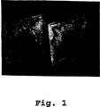
図1は切削工具インサートの接触表面を3Xの倍率で示し、これらのインサートは、異なるトレーであるが、1410℃の通常の生産用焼結及び同一焼結バッチにおける焼結の同一履歴を持つ。
本発明の方法にしたがう超硬合金またはサーメットの物体は、20wt%以下のZrO2好ましくは10wt%以下のZrO2及び最も好ましくは5wt%以下のZrO2を含有するY2O3またはY2O3ベース、または相当体積量の他の耐熱酸化物例えばAl2O3またはそれらの組み合わせ物、のカバー層で被覆したグラフィとトレーで焼結される。Mo、W、Nb、Zr、Ta、好ましくMoまたはWまたはそれらの混合物のような耐熱金属、及び/または好ましくはZrO2基のような耐熱性酸化物、の中間層を1種以上好ましく被覆する。これらの層の平均厚さは、それぞれが、10μm以上、好ましくは20〜300μm、最も好ましくは50〜150μmにする必要がある。
中間の単一層または複数層の材料を選ぶ場合に最も重要な性質は、下側に置かれるグラファイト表面とイットリア化合物またはイットリア基化合物の最上被膜との双方に対する強い付着性である。しかしながら、これらの中間層材料が、室温から通常は約1550℃である作業温度までの温度範囲で熱的に安定であることも重要である。さらに、それら中間層材料が、隣接する材料の機能に悪影響を及ぼさないように、隣接する材料と反応しないことが必要である。
被覆は、既知の粉末スプレー法好ましくはプラズマスプレー法により被覆され、主分布が10〜100μm好ましくは10〜75μmの範囲内である粒または塊サイズを持つ粉末を使用する。容器から吹き付け器を通る粉末流れに関するスプレー工程を促進するために、粉末は好ましくは塊である。
代わりの実施態様において、被覆は、考慮した粉末が入っているスプレーを適用することによって形成され、その後、乾燥及び焼結がされる。化学蒸着法も使用することができる。
実施例1
切削工具インサートは、4種の異なる超硬合金粉末混合物から加圧成形された。これらのうち2種は、WC−10wt%Coに、高炭素成分及び低炭素成分を含み、それぞれは材料A−hc及び材料A−lcと示され、且つ、残りの2種は、WC相当量を5wt%のTiCの添加で代えることにより作られた。また、高炭素成分及び低炭素成分に区別されているこれらは、それぞれ材料B−hc及び材料B−lcと示される。これらの加圧成形されたインサートは、3種の異なるトレーに配置された。すなわち、
トレー1:非被覆グラファイトトレー(先行技術)
トレー2:約60〜100μmの被膜厚さのZrO2−20%Y2O3(Metco202)のプラズマスプレー被膜を有するグラファイトトレー(先行技術)
トレー3:約10〜15μmの厚みのY2O3のプラズマスプレー最上被膜、及びプラズマスプレー法により被覆した約20〜50μmの厚さのMo中間層を有するグラファイトトレー(本発明)
注:被膜厚さはトレーを貫く金属組織断面で決定した。
長時間焼結法は、1450℃で50時間、10ミリバールのCO雰囲気中で行われた。冷却後、焼結された物体は、それらが如何に強く冶金学的反応によって支持体に接着したかに関して試験をしたさ。得られた結果を表1に示す。n−rはトレーと反応しないことを表し、c−rはある程度の反応をするが目立った付着のないことを表し、且つ非常に強い粘着であもって付着することを表す。

実施例2
切削工具インサートは、WC−6.5wt%Co−8.5wt%(TiC+NbC+TaC)からなる超硬合金粉末混合物から加圧成形された。焼結は1450℃で実施され、且つ従来知られているようにインサートの表面領域にバインダー相を豊富にするために冷却速度が決定された。また、この処理はインサート表面にCo層の形成をもたらした。これらのインサートは、各トレーにつき約100個を次のトレーで焼結した。すなわち、
トレー1:約60〜100μmの被膜厚さのZrO2−20%Y2O3のプラズマスプレー被膜を有するグラファイトトレー(先行技術)
トレー2:約100〜150μmの厚さのY2O3のプラズマスプレー被膜、及び約100〜150μmの厚さのプラズマスプレーMoの中間層を有するグラファイトトレー(本発明)
注:被膜厚さはトレーを貫く金属組織断面で決定した。
約60分の温度保持時間で標準的な方法にしたがう焼結後、トレー1で焼結されたインサートは、トレー材料とインサートの間で過剰な反応を示し、インサートにトレー材料小片が強く付着しないが、約10%のインサートがトレーから取り出すことが困難であった。これとは反対に、トレー2で焼結されたインサートは、トレー材料と反応する傾向を示さなかった。このインサートは容易に取り出せた。
図1にこの実施例の2種の切削工具の接触表面を3xの倍率で示し、左側のインサートはトレー1で焼結され、右側のインサートはトレー2で焼結された。左側のインサートはトレー材料に強く付着することを示し、一方右側のインサートは実質的に影響を受けなかった。
マイクロプローブ分析はトレー2で焼結されたインサート接触表面にイットリウムの存在を示した。
実施例3
WC−9.5wt%Co−35wt%(TiC+NbC+TaC)からなる超硬合金粉末混合物から加圧成形された切削工具インサートは、次の形式のトレー上で1520℃で通常の製法で焼結された。すなわち、
トレー1:約60〜100μmの被膜厚さのZrO2−20%Y2O3のプラズマスプレー被膜を有するグラファイトトレー(先行技術)
トレー2:約100〜150μmの厚さのY2O3のプラズマスプレー被膜、及び約100〜150μmの厚さのプラズマスプレーMoの中間層を有するグラファイトトレー(本発明)
この焼結温度と所定の超硬合金でもって、トレー1の寿命は2または3回の焼結後、ほとんどの被膜が取り除かれるためにこのトレーは使用中止し、一方トレー2は20回の焼結回数を越える寿命が得られた。
実施例4
切削工具インサートは、WC−10wt%Co−6wt%(TiC+NbC+TaC)を含み且つ低炭素成分を含有する超硬合金粉末混合物から加圧成形された。加圧成形されたインサートは異なる2種のトレーにそれぞれ100個のインサートが配置され、1410℃で1時間焼結された。すなわち、
トレー1:約60〜100μmの被膜厚さのZrO2−20%Y2O3(metco202)のプラズマスプレー被膜を有するグラファイトトレー(先行技術)
トレー2:トレー1のようなZrO2−20%Y2O3(metco202)で被覆し、しかし約10〜15μmの厚さのY2O3の最上プラズマスプレー被膜を有するグラファイトトレー(本発明)
被膜の厚さは焼結試験の後トレーを貫く金属組織断面で評価した。
焼結後、トレー1のインサートは、強く付着し、力を加えることで取り外すことができた。取り外されたインサートの60%が、その底の面に付着するトレー被膜小片が認められ、これらの付着は研削加工ホイールを使用することによってようやく除去することができた。このトレーすなわちトレー1はその表面被膜に相当する損傷が認められた。
トレー2のインサートは、しかしながら、トレーをひっくり返して容易に取り外せた。
実施例5
採鉱工具用途の超硬合金は、WC−12wt%Coを含有する超硬合金粉末混合物から加圧成形された。この物体は1個あたり300g以下の重さであった。生産用焼結が次のトレーで実施された。すなわち、
トレー1:約60〜100μmの被膜厚さのZrO2−20%Y2O3のプラズマスプレー被膜を有するグラファイトトレー(先行技術)
トレー2:約100〜150μmの厚さのY2O3のプラズマスプレー被膜、及び約100〜150μmの厚さのプラズマスプレーMoの中間層を有するグラファイトトレー(本発明)
1450℃の焼結温度で、トレー1は2回だけ使用可能であった。超硬合金中の比較的多くの量のコバルトと大きなユニットの重さとが、本体とトレー材料との過多な反応を生じさせた。この温度で同一超硬合金材料と同一ユニットの重さとで、トレー2は6回以上の焼結に使用できた。The present invention relates to a tray for use in sintering powder metallurgy products such as cemented carbide and cermet.
Cemented carbides and cermets include Ti, Zr, Hf, V, Nb, Ta, Cr, Mo and / or W carbides, nitriding in binders based essentially on Co and / or Ni and / or Fe. And / or an alloy mainly containing hard components based on carbonitrides. These are produced by a common powder metallurgy process comprising kneading, pressing and sintering of a powder mixture containing a hard component and a powder forming a binder phase.
The compacted body after pressure molding had a porosity of about 50% by volume. Subsequently, a sufficiently dense product was produced by liquid phase sintering at a temperature in the general range of 1300 to 1550 ° C., where the binder metal was in the liquid state and was actually dependent on the composition.
In the manufacture of cemented carbides and cermets, most sintering methods are available in various industrial vacuums such as one torr or more and mixtures of H 2 with CO, CO 2 , Ar, N 2 , CH 4 etc. In the gas atmosphere, the object to be sintered is placed on a graphite tray. These trays usually coat the surface to minimize the effect of graphite in contact with the object to be sintered and the furnace atmosphere. For example, see “Sintering-Technical and Basic Principles” by H. Kolaska et al., “Powder Merallurgy of Hardmetals, EPMA Lecture Series, European Powder Metallugy Association, Shrewsbury, UK, 1995, P. 6/9-6/10”. . In practice, Al 2 O 3 or ZrO 2 based coatings are coated by thermal spraying, typically plasma powder spraying. That is, these coatings act as a barrier layer that prevents the reaction that occurs between the object to be sintered and the tray. This reaction poses various challenges, which are carbon absorption from the tray and distortion of the sintered body.
In essence, these graphite trays with a barrier layer can be reused for as many sintering cycles as possible without causing tray degradation, i.e. the barrier layer remains inert and It is to maintain high adhesion to the graphite tray. In general, the need for re-grinding and re-coating of the tray is determined by those skilled in the art when the coating is peeled away to the extent that it is readily visible to the naked eye of those skilled in the art.
This degradation is due to a metallurgical reaction that occurs between the cemented carbide object and the tray and is a problem to be avoided caused by adhesion. Individual grains or pieces of the coating on the very surface of the coating are torn off. This problem is particularly encountered when sintering large cemented carbide bodies that contain relatively many binder phase components, and these conditions promote adhesion.
Surprisingly now, the provision of a yttria (Y 2 O 3 ) based barrier layer compares the life of coated trays used for production sintering to previous coated trays that were reground and recoated. Was found to increase significantly. This is a significant saving in manufacturing costs and results in an improved quality sintered product.
FIG. 1 shows the contact surface of a cutting tool insert at a magnification of 3 ×, which are different trays but have the same history of sintering in a normal production sintering at 1410 ° C. and in the same sintering batch.
A cemented carbide or cermet body according to the method of the present invention comprises Y 2 O 3 or Y 2 O containing 20 wt% or less ZrO 2, preferably 10 wt% or less ZrO 2, and most preferably 5 wt% or less ZrO 2. Sintered in graphy and trays coated with a cover layer of 3 bases, or equivalent volume of other refractory oxides such as Al 2 O 3 or combinations thereof. One or more intermediate layers of Mo, W, Nb, Zr, Ta, preferably a refractory metal such as Mo or W or mixtures thereof, and / or a refractory oxide such as a ZrO 2 group are preferably coated. . Each of these layers should have an average thickness of 10 μm or more, preferably 20 to 300 μm, and most preferably 50 to 150 μm.
The most important property when choosing an intermediate single-layer or multi-layer material is the strong adhesion to both the underlying graphite surface and the top coat of yttria compounds or yttria-based compounds. However, it is also important that these interlayer materials be thermally stable in the temperature range from room temperature to the working temperature, which is usually about 1550 ° C. Furthermore, it is necessary that the interlayer material does not react with the adjacent material so that the function of the adjacent material is not adversely affected.
The coating is applied by a known powder spraying method, preferably a plasma spraying method, and a powder having a grain or mass size with a main distribution in the range of 10-100 μm, preferably 10-75 μm. The powder is preferably agglomerated to facilitate the spraying process for powder flow from the container through the sprayer.
In an alternative embodiment, the coating is formed by applying a spray containing the contemplated powder, followed by drying and sintering. Chemical vapor deposition can also be used.
Example 1
The cutting tool insert was pressed from four different cemented carbide powder mixtures. Two of these include WC-10 wt% Co with a high carbon component and a low carbon component, which are designated as material A-hc and material A-lc, respectively, and the remaining two are WC equivalents Was replaced by the addition of 5 wt% TiC. Moreover, these which are distinguished into a high carbon component and a low carbon component are shown as material B-hc and material B-lc, respectively. These press molded inserts were placed in three different trays. That is,
Tray 1: Uncoated graphite tray (prior art)
Tray 2: Graphite tray with a plasma spray coating of ZrO 2 -20% Y 2 O 3 (Metco 202) with a film thickness of about 60-100 μm (prior art)
Tray 3: Graphite tray having about 10-15 μm thick Y 2 O 3 plasma spray top coat and about 20-50 μm thick Mo intermediate layer coated by plasma spray method (invention)
Note: The film thickness was determined by the cross-section of the metal structure that penetrates the tray.
The long-term sintering method was performed at 1450 ° C. for 50 hours in a 10 mbar CO atmosphere. After cooling, the sintered bodies were tested for how strongly they adhered to the support by a metallurgical reaction. The obtained results are shown in Table 1. n-r indicates that it does not react with the tray, cr indicates that it reacts to some extent but no noticeable adhesion, and that it adheres with very strong adhesion.
Example 2
The cutting tool insert was pressed from a cemented carbide powder mixture consisting of WC-6.5 wt% Co-8.5 wt% (TiC + NbC + TaC). Sintering was performed at 1450 ° C. and the cooling rate was determined to enrich the binder phase in the surface area of the insert as is known in the art. This treatment also resulted in the formation of a Co layer on the insert surface. About 100 of these inserts were sintered in the next tray for each tray. That is,
Tray 1: Graphite tray with ZrO 2 -20% Y 2 O 3 plasma spray coating of about 60-100 μm thickness (prior art)
Tray 2: Graphite tray (invention) having a plasma spray coating of about 100-150 μm thick Y 2 O 3 and an intermediate layer of about 100-150 μm thick plasma spray Mo
Note: The film thickness was determined by the cross-section of the metal structure that penetrates the tray.
After sintering according to standard methods with a temperature holding time of about 60 minutes, the insert sintered in tray 1 shows excessive reaction between the tray material and the insert, and the tray material pieces do not adhere strongly to the insert. However, about 10% of the inserts were difficult to remove from the tray. In contrast, the insert sintered in tray 2 did not show a tendency to react with the tray material. This insert was easily removed.
FIG. 1 shows the contact surfaces of the two cutting tools of this example at a magnification of 3 ×, with the left insert being sintered with tray 1 and the right insert being sintered with tray 2. The left insert showed a strong adhesion to the tray material, while the right insert was substantially unaffected.
Microprobe analysis showed the presence of yttrium on the insert contact surface sintered in tray 2.
Example 3
Cutting tool inserts pressed from a cemented carbide powder mixture consisting of WC-9.5 wt% Co-35 wt% (TiC + NbC + TaC) were sintered at 1520 ° C. on a conventional tray at the usual process. That is,
Tray 1: Graphite tray with ZrO 2 -20% Y 2 O 3 plasma spray coating of about 60-100 μm thickness (prior art)
Tray 2: Graphite tray (invention) having a plasma spray coating of about 100-150 μm thick Y 2 O 3 and an intermediate layer of about 100-150 μm thick plasma spray Mo
With this sintering temperature and a given cemented carbide, the life of the tray 1 is discontinued after 2 or 3 times of sintering, since most of the coating is removed, while the tray 2 is fired 20 times. Lifespan exceeding the number of bindings was obtained.
Example 4
The cutting tool insert was pressed from a cemented carbide powder mixture containing WC-10 wt% Co-6 wt% (TiC + NbC + TaC) and containing a low carbon component. The press-molded inserts were 100 inserts each in two different trays and sintered at 1410 ° C. for 1 hour. That is,
Tray 1: Graphite tray having a plasma spray coating of ZrO 2 -20% Y 2 O 3 (metco 202) with a film thickness of about 60-100 μm (prior art)
Tray 2: Graphite tray coated with ZrO 2 -20% Y 2 O 3 (metco 202) like tray 1, but with a top plasma spray coating of Y 2 O 3 about 10-15 μm thick (invention)
The thickness of the coating was evaluated by a cross section of the metal structure penetrating the tray after the sintering test.
After sintering, the insert of tray 1 adhered strongly and could be removed by applying force. 60% of the removed inserts were found to have a small piece of tray coating adhering to the bottom surface, and these deposits could only be removed by using a grinding wheel. In this tray, that is, tray 1, damage corresponding to the surface coating was observed.
The insert in tray 2 could, however, be easily removed by turning the tray over.
Example 5
A cemented carbide for mining tool application was pressure molded from a cemented carbide powder mixture containing WC-12 wt% Co. This object weighed 300 g or less. Production sintering was performed on the following trays. That is,
Tray 1: Graphite tray with ZrO 2 -20% Y 2 O 3 plasma spray coating of about 60-100 μm thickness (prior art)
Tray 2: Graphite tray (invention) having a plasma spray coating of about 100-150 μm thick Y 2 O 3 and an intermediate layer of about 100-150 μm thick plasma spray Mo
At a sintering temperature of 1450 ° C., tray 1 could only be used twice. The relatively large amount of cobalt in the cemented carbide and the weight of the large unit caused excessive reaction between the body and the tray material. At this temperature, the tray 2 could be used for six or more sinterings with the same cemented carbide material and the same unit weight.
Claims (2)
20wt%以下のZrO2を含有するY2O 3 の、10μm以上の平均厚さであるカバー層と、Mo、W、Nb、Zr、Ta及びそれらの組み合わせから成る群から選択された少なくとも1種の耐熱金属を含有する10μm以上の平均厚さである1層以上の中間層とから成る被膜を有するグラファイトトレーを使用することを特徴とする超硬合金またはサーメットの物体の焼結方法。A method of placing a cemented carbide or cermet object on a graphite tray and sintering it,
Of Y 2 O 3 containing 20 wt% or less of ZrO 2, and the cover layer is the average thickness of more than 10μm, Mo, W, Nb, Zr, at least one selected from the group consisting of Ta and combinations thereof sintering method of the object cemented carbide or cermet, characterized in that the graphite trays that have a coating consisting of one or more layers of the intermediate layer is the average 10μm or more thick containing refractory metal used.
Applications Claiming Priority (3)
| Application Number | Priority Date | Filing Date | Title |
|---|---|---|---|
| SE9601567-2 | 1996-04-23 | ||
| SE9601567A SE506482C2 (en) | 1996-04-23 | 1996-04-23 | sintering Surface |
| PCT/SE1997/000660 WO1997040203A1 (en) | 1996-04-23 | 1997-04-18 | Sintering tray |
Publications (2)
| Publication Number | Publication Date |
|---|---|
| JP2000509102A JP2000509102A (en) | 2000-07-18 |
| JP4170392B2 true JP4170392B2 (en) | 2008-10-22 |
Family
ID=20402330
Family Applications (1)
| Application Number | Title | Priority Date | Filing Date |
|---|---|---|---|
| JP53798797A Expired - Lifetime JP4170392B2 (en) | 1996-04-23 | 1997-04-18 | Sintering tray |
Country Status (8)
| Country | Link |
|---|---|
| US (1) | US5993970A (en) |
| EP (1) | EP0958394B1 (en) |
| JP (1) | JP4170392B2 (en) |
| AT (1) | ATE226262T1 (en) |
| DE (1) | DE69716475T2 (en) |
| IL (1) | IL126177A (en) |
| SE (1) | SE506482C2 (en) |
| WO (1) | WO1997040203A1 (en) |
Cited By (1)
| Publication number | Priority date | Publication date | Assignee | Title |
|---|---|---|---|---|
| KR101797347B1 (en) * | 2016-03-08 | 2017-12-12 | (주)하이엠시 | The Carbon·Alumina mixed paper, the method of manufacturing it and the heat treatment tray |
Families Citing this family (21)
| Publication number | Priority date | Publication date | Assignee | Title |
|---|---|---|---|---|
| JP2002371383A (en) * | 2001-06-18 | 2002-12-26 | Shin Etsu Chem Co Ltd | Heat resistant coated member |
| JP2003073794A (en) * | 2001-06-18 | 2003-03-12 | Shin Etsu Chem Co Ltd | Heat-resistant coated member |
| US6852433B2 (en) * | 2002-07-19 | 2005-02-08 | Shin-Etsu Chemical Co., Ltd. | Rare-earth oxide thermal spray coated articles and powders for thermal spraying |
| JP2004190056A (en) * | 2002-12-09 | 2004-07-08 | Shin Etsu Chem Co Ltd | Heat-resistant coated member |
| KR101168422B1 (en) | 2002-11-20 | 2012-07-25 | 신에쓰 가가꾸 고교 가부시끼가이샤 | Making Method of Heat Resistant Coated Member |
| EP1435501B1 (en) * | 2002-12-30 | 2006-02-22 | Shin-Etsu Chemical Co., Ltd. | Heat-resistant coated member |
| JP4716042B2 (en) * | 2003-03-28 | 2011-07-06 | 信越化学工業株式会社 | Heat-resistant covering material |
| JP4189676B2 (en) * | 2003-03-28 | 2008-12-03 | 信越化学工業株式会社 | Heat-resistant covering material |
| JP2005008483A (en) * | 2003-06-19 | 2005-01-13 | Shin Etsu Chem Co Ltd | Coating member and its manufacturing process |
| JP2005281032A (en) * | 2004-03-29 | 2005-10-13 | Shinwa Kogyo Kk | Graphite tray for sintering |
| JP2006199515A (en) * | 2005-01-18 | 2006-08-03 | Hitachi Tool Engineering Ltd | Heat-resistant coating member |
| JP4879843B2 (en) * | 2007-08-20 | 2012-02-22 | インターメタリックス株式会社 | Method for producing NdFeB-based sintered magnet and mold for producing NdFeB sintered magnet |
| EP2225061B1 (en) * | 2007-12-21 | 2019-04-24 | Sandvik Intellectual Property AB | Method of making cutting tools |
| JP4952953B2 (en) * | 2008-09-26 | 2012-06-13 | 信越化学工業株式会社 | Method for manufacturing a setter for sintering super hard material or cermet material |
| SE533070C2 (en) * | 2008-11-10 | 2010-06-22 | Seco Tools Ab | Ways to make cutting tools |
| EP2406570B1 (en) * | 2009-03-12 | 2016-01-27 | 3M Innovative Properties Company | System and method for sintering dental restorations |
| EP2821165A1 (en) * | 2013-07-03 | 2015-01-07 | Sandvik Intellectual Property AB | A sintered cermet or cemented carbide body and method of producing it |
| CN107848868B (en) * | 2015-07-10 | 2021-06-04 | 恩特格里斯公司 | Coating for glass shaping mold and mold comprising same |
| JP7055951B2 (en) * | 2019-10-01 | 2022-04-19 | 東京窯業株式会社 | Firing jig |
| KR102416899B1 (en) * | 2020-05-15 | 2022-07-05 | 피에스테크놀러지(주) | Jig for sintering and method for preparation of jig for sintering |
| CN113604769A (en) * | 2021-06-30 | 2021-11-05 | 厦门金鹭特种合金有限公司 | Color-difference-preventing interlayer for sintering low-Co metal ceramic |
Family Cites Families (5)
| Publication number | Priority date | Publication date | Assignee | Title |
|---|---|---|---|---|
| US4357382A (en) * | 1980-11-06 | 1982-11-02 | Fansteel Inc. | Coated cemented carbide bodies |
| JPS6114187A (en) * | 1984-06-27 | 1986-01-22 | 日本特殊陶業株式会社 | Reinforced board-like sintered body |
| CH670874A5 (en) * | 1986-02-04 | 1989-07-14 | Castolin Sa | |
| US4701384A (en) * | 1987-01-20 | 1987-10-20 | Gte Laboratories Incorporated | Composite coatings on cemented carbide substrates |
| US5304519A (en) * | 1992-10-28 | 1994-04-19 | Praxair S.T. Technology, Inc. | Powder feed composition for forming a refraction oxide coating, process used and article so produced |
-
1996
- 1996-04-23 SE SE9601567A patent/SE506482C2/en not_active IP Right Cessation
-
1997
- 1997-04-14 US US08/837,094 patent/US5993970A/en not_active Expired - Lifetime
- 1997-04-18 IL IL12617797A patent/IL126177A/en not_active IP Right Cessation
- 1997-04-18 EP EP97921037A patent/EP0958394B1/en not_active Expired - Lifetime
- 1997-04-18 AT AT97921037T patent/ATE226262T1/en active
- 1997-04-18 DE DE69716475T patent/DE69716475T2/en not_active Expired - Lifetime
- 1997-04-18 JP JP53798797A patent/JP4170392B2/en not_active Expired - Lifetime
- 1997-04-18 WO PCT/SE1997/000660 patent/WO1997040203A1/en active IP Right Grant
Cited By (1)
| Publication number | Priority date | Publication date | Assignee | Title |
|---|---|---|---|---|
| KR101797347B1 (en) * | 2016-03-08 | 2017-12-12 | (주)하이엠시 | The Carbon·Alumina mixed paper, the method of manufacturing it and the heat treatment tray |
Also Published As
| Publication number | Publication date |
|---|---|
| SE9601567D0 (en) | 1996-04-23 |
| WO1997040203A1 (en) | 1997-10-30 |
| EP0958394B1 (en) | 2002-10-16 |
| ATE226262T1 (en) | 2002-11-15 |
| SE9601567L (en) | 1997-10-24 |
| SE506482C2 (en) | 1997-12-22 |
| EP0958394A1 (en) | 1999-11-24 |
| JP2000509102A (en) | 2000-07-18 |
| IL126177A (en) | 2001-06-14 |
| DE69716475T2 (en) | 2003-02-27 |
| US5993970A (en) | 1999-11-30 |
| IL126177A0 (en) | 1999-05-09 |
| DE69716475D1 (en) | 2002-11-21 |
Similar Documents
| Publication | Publication Date | Title |
|---|---|---|
| JP4170392B2 (en) | Sintering tray | |
| JP4842962B2 (en) | Sintered cemented carbide using vanadium as gradient forming element | |
| JP4330859B2 (en) | Coated cemented carbide and method for producing the same | |
| JP2009142982A (en) | Coated cutting tool insert | |
| JP2003205406A (en) | Coated cutting tool insert formed of cemented carbide and coated film | |
| WO2009035404A1 (en) | Insert for milling of cast iron | |
| US6071464A (en) | Process for modifying surfaces of hard materials and cutting tools | |
| JP2684688B2 (en) | Surface-coated tungsten carbide based cemented carbide for cutting tools | |
| JP2600359B2 (en) | Manufacturing method of surface coated tungsten carbide based cemented carbide cutting tool | |
| JP2539922B2 (en) | Diamond coated cemented carbide | |
| JPH04289003A (en) | Cutting tool made of surface-coated ticn-cermet having excellent toughness | |
| JP2003048004A (en) | Rolling roll made of composite material and method of manufacturing it | |
| JP3368794B2 (en) | Surface-coated cermet throw-away type cutting insert with a hard coating layer with excellent fracture resistance | |
| JP2970016B2 (en) | Hard layer coated cemented carbide cutting tool | |
| JPH05212604A (en) | Ceramics cutting tool coated with hard layer | |
| JP2508523B2 (en) | Surface coated cemented carbide cutting tool | |
| JP2717925B2 (en) | Cemented carbide and its manufacturing method | |
| JPH0610089A (en) | Coated sintered hard alloy | |
| JPH07164209A (en) | Composite cutting tool | |
| JPH05339753A (en) | Surface-coated cutting tool made of ti base carbon-nitrogen-boron oxide cermet and excellent in adhesion of hard coating layer | |
| EP2201153A1 (en) | Insert for milling of cast iron | |
| JPH024972A (en) | Surface-coated cermet for cutting tool | |
| JP2008038174A (en) | Cemented carbide and coated cemented carbide | |
| JPH05271943A (en) | Cutting tool made of surface coated ti series carbide-nitride-boride base cermet excellent in adhesion of hard coated layer | |
| JPH0578845A (en) | Sintered alloy coated with high-adhesion diamond |
Legal Events
| Date | Code | Title | Description |
|---|---|---|---|
| A521 | Request for written amendment filed |
Free format text: JAPANESE INTERMEDIATE CODE: A523 Effective date: 20040415 |
|
| A621 | Written request for application examination |
Free format text: JAPANESE INTERMEDIATE CODE: A621 Effective date: 20040415 Free format text: JAPANESE INTERMEDIATE CODE: A621 Effective date: 20040419 |
|
| A625 | Written request for application examination (by other person) |
Free format text: JAPANESE INTERMEDIATE CODE: A625 Effective date: 20040419 |
|
| A072 | Dismissal of procedure [no reply to invitation to correct request for examination] |
Free format text: JAPANESE INTERMEDIATE CODE: A072 Effective date: 20040831 |
|
| A711 | Notification of change in applicant |
Free format text: JAPANESE INTERMEDIATE CODE: A711 Effective date: 20050606 |
|
| A711 | Notification of change in applicant |
Free format text: JAPANESE INTERMEDIATE CODE: A711 Effective date: 20051006 |
|
| A131 | Notification of reasons for refusal |
Free format text: JAPANESE INTERMEDIATE CODE: A131 Effective date: 20070814 |
|
| A601 | Written request for extension of time |
Free format text: JAPANESE INTERMEDIATE CODE: A601 Effective date: 20071113 |
|
| A602 | Written permission of extension of time |
Free format text: JAPANESE INTERMEDIATE CODE: A602 Effective date: 20071221 |
|
| A521 | Request for written amendment filed |
Free format text: JAPANESE INTERMEDIATE CODE: A523 Effective date: 20080201 |
|
| TRDD | Decision of grant or rejection written | ||
| A01 | Written decision to grant a patent or to grant a registration (utility model) |
Free format text: JAPANESE INTERMEDIATE CODE: A01 Effective date: 20080708 |
|
| A01 | Written decision to grant a patent or to grant a registration (utility model) |
Free format text: JAPANESE INTERMEDIATE CODE: A01 |
|
| A61 | First payment of annual fees (during grant procedure) |
Free format text: JAPANESE INTERMEDIATE CODE: A61 Effective date: 20080807 |
|
| FPAY | Renewal fee payment (event date is renewal date of database) |
Free format text: PAYMENT UNTIL: 20110815 Year of fee payment: 3 |
|
| R150 | Certificate of patent or registration of utility model |
Free format text: JAPANESE INTERMEDIATE CODE: R150 |
|
| FPAY | Renewal fee payment (event date is renewal date of database) |
Free format text: PAYMENT UNTIL: 20110815 Year of fee payment: 3 |
|
| FPAY | Renewal fee payment (event date is renewal date of database) |
Free format text: PAYMENT UNTIL: 20120815 Year of fee payment: 4 |
|
| FPAY | Renewal fee payment (event date is renewal date of database) |
Free format text: PAYMENT UNTIL: 20130815 Year of fee payment: 5 |
|
| R250 | Receipt of annual fees |
Free format text: JAPANESE INTERMEDIATE CODE: R250 |
|
| R250 | Receipt of annual fees |
Free format text: JAPANESE INTERMEDIATE CODE: R250 |
|
| R250 | Receipt of annual fees |
Free format text: JAPANESE INTERMEDIATE CODE: R250 |
|
| R250 | Receipt of annual fees |
Free format text: JAPANESE INTERMEDIATE CODE: R250 |
|
| EXPY | Cancellation because of completion of term |